Abstract
Controllable shock wave (CSW) technology offers a promising approach for improving roof cavability and safety in underground mining, yet its field-scale mechanisms remain insufficiently clarified. This study develops and validates an optimized CSW pre-cracking procedure for hard top coal at the Liuxiang Coal Mine. A series of CSW-induced fracturing experiments were conducted across multiple boreholes under real operating conditions, and the causal relationships between loading parameters, induced fracture propagation, and mining performance were systematically evaluated. Segmented water injection leak detection was used to quantify fracture development in the No. 3 coal seam. The results demonstrate that CSW significantly enhances top-coal cavability: the proportion of large coal blocks was reduced by approximately 25%, and the average roof pressure step distance decreased from the baseline of 16.12–20.03 m to 13.12–13.82 m. These improvements indicate more efficient energy release, a more stable roof structure, and safer working conditions. Overall, this study provides a technically verified and operationally optimized CSW procedure, highlighting its strong potential to support safer and more sustainable hard top-coal mining.
1. Introduction
Controllable shock wave (CSW) technology is a physical fracturing method based on high-voltage pulse discharge. Its core principle involves the instantaneous release of stored electrical energy within a downhole tool, generating a high-pressure plasma channel in a liquid medium (typically water). This rapid expansion creates a steep-fronted, controllable shock wave that propagates into the surrounding coal-rock mass as a stress wave, inducing dynamic tensile and shear failure and initiating and extending fractures. Preliminary engineering exploration has confirmed the feasibility and effectiveness of CSW-induced fracturing and permeability enhancement technology [1]; however, further development and promotion of this technology are constrained by an incomplete understanding of the fracturing process and its underlying mechanism [2]. Therefore, it is necessary to investigate further the coal-rock response to CSW and its mechanism of action [3], which provides a theoretical basis for optimizing and advancing CSW-induced fracturing and permeability enhancement technology [4,5]. Significant progress has been made in the mechanisms and experimental studies of shock wave-induced coal seam fracturing and permeability enhancement [6,7]. In particular, research on pore size distribution adjustment [8], pore structure classification, permeability variation, pore structure evolution, and crack propagation in the coal samples of different ranks [9], as well as the influence of coal-rock composition on crack initiation and development [10], has deepened our understanding of CSW effects.
Under external forces [8], geological media can display both elastic and plastic behavior [11]. The manifestation of elasticity or plasticity in geological media is influenced not only by environmental conditions such as rock temperature and static pressure [12,13] but also by persistent vibration waves acting on rock particles, which can be considered as elastic or seismic waves [14]. Wave propagation in rock media depends on three main aspects [15]: the intrinsic properties of the rock, including lithology, density, compaction, cohesion, porosity, pore shape, material composition, and anisotropy [16]; the characteristics of fluids in pores and fractures, such as fluid pressure, type, composition, saturation, viscosity, wettability, phase state, and density [17]; and the geological environment, including rock structure [18], geostress, temperature, formation history, sedimentary environment, joints, and fractures [19]. Transmission and reflection analysis of elastic waves at planar interfaces provides insight into the behavior of penetrating cracks with relatively large lengths and spacing [20,21]. In saturated porous media, wave dispersion occurs due to fluid viscosity [22]; below the critical frequency [23], the effect of fluid viscosity on plane waves can be neglected [24]. While attenuation is generally insensitive to medium anisotropy, in high-frequency regions [25], low fluid viscosity [26] increases the directional dependence of attenuation [27]. Experimental studies further indicate that greater stiffness of rock interfaces leads to higher transmission coefficients [28], whereas longer non-penetrating cracks result in the greater attenuation of stress wave amplitude [29,30].
While these laboratory-scale studies provide a fundamental theoretical framework for stress wave interaction with coal-rock media, their direct translation into predictive models and optimized operational parameters for field-scale hard top-coal pre-cracking remains a significant challenge, primarily due to the scale and complexity of in situ geological conditions. The effectiveness of CSW in field operations is influenced by various geological constraints, which can be categorized into three types [31,32,33]: coal seam structure and roof/coal–seam/floor combination characteristics, including roof–floor relationships, coal layering, gangue inclusions, and thickness [34]; coal seam physical properties, such as porosity, permeability, and reservoir pressure [35]; and external geological conditions, including temperature, stress field, and groundwater flow [36]. Despite extensive studies on CSW mechanisms, research specifically addressing the pre-cracking of hard top coal is still limited. This gap in field-applicable knowledge directly translates to significant engineering challenges at the mining face. Without reliable, field-validated CSW parameter guidelines for hard top coal, operations frequently face: (1) Poor Top Coal Cavability: The hard coal fails to fragment adequately, resulting in oversized coal blocks that clog support outlets and transfer systems, severely hampering production efficiency and increasing equipment wear. (2) Unmanaged Roof Pressure: The intact, hard roof-coal structure leads to high stress concentration and large periodic weighting intervals, posing safety risks to supports and personnel. (3) Low Recovery Rate: Ineffective pre-fracturing leaves a substantial portion of top coal unrecovered in the goaf. These difficulties underscore the urgent on-site need for a scientifically grounded CSW pre-cracking strategy tailored to hard top-coal conditions. Consequently, the design of field CSW operations must carefully account for the site-specific mechanical properties of the target coal-rock mass, as these properties fundamentally govern shock wave attenuation and the resultant fracture patterns.
This study focuses on the hard top coal of the Liuxiang Coal Mine and aims to conduct CSW-induced fracturing experiments on multiple boreholes under operational conditions and analyze the fracture mechanism; establish an optimized CSW pre-fracturing procedure by adjusting operational parameters and evaluating the effects; and monitor coal behavior in the test area, assess segmented water injection leak detection results, and investigate fracture development in the No. 3 coal seam under field conditions.
2. Test Plan
2.1. Test Site
The field tests were conducted in the No. 3 coal seam of the Liuxiang Coal Mine. This seam is characterized as a hard top coal with an average thickness of 6.5 m and a Protodyakonov coefficient of 2.5–3.0, indicating high strength and low initial fracture development. The immediate roof consists of 8–12 m of fine-grained sandstone, which is relatively intact and competent. The main roof is composed of thicker sandstone and siltstone strata. The immediate floor is typically mudstone or sandy mudstone with a thickness of 2–4 m. The test areas (30109 return airway and 30112 transport channel) are located within a relatively stable geological block. The regional geological structure is simple, with no large-scale faults or intense folds identified within the immediate test vicinity. The in situ stress field is dominated by gravitational stress. This specific combination of hard coal, a competent roof, and simple structure presents a typical scenario where CSW pre-cracking is targeted to improve cavability and manage roof pressure.
2.2. Test Content
The core objective of this study is to investigate the operational parameters, on-site performance evaluation, and hazard identification associated with controllable shock wave (CSW) pre-cracking in hard top-coal seams. Following a preliminary field survey, a series of CSW pre-cracking experiments were carried out in the No. 3 coal seam of the Liuxiang Coal Mine. The test design and field procedures were implemented in accordance with the general requirements of Chinese mining engineering standards, including GB/T 23561 [37] (methods for determining physical and mechanical properties of coal and rock). Furthermore, the experimental workflow was based on validated CSW and shock wave fracturing procedures reported in previous studies [38,39].
The purpose of the field tests was to optimize CSW operating parameters and evaluation methods, thereby verifying the feasibility of CSW pre-cracking technology for weakening hard top coal and roof strata. Multiple groups of boreholes were constructed under real mining conditions, and CSW fracturing tests were performed by systematically varying key operational parameters. By comparing the fracturing response and effectiveness under different configurations, a practical CSW operation strategy for pre-cracking hard coal seams was established.
The specific research components are summarized as follows:
- (a)
- Parameter design for CSW pre-splitting of top coal
The CSW device requires the drilling rig to use cable-type drill pipes to insert and retrieve the tool from the borehole. Tool deployment is operationally challenging due to borehole curvature. Therefore, improvements in drilling construction parameters, borehole trajectory control, and CSW tool optimization were necessary to ensure smooth insertion and withdrawal.
Because the fracturing performance of CSW varies with the physical and mechanical properties of coal and roof strata, it was essential to analyze the geological conditions, determine the borehole layout, and evaluate the relationship between borehole construction and working-face position. Accordingly, we designed and compared different operational parameters—such as the number of boreholes, borehole spacing, spacing between shock wave loading points, and the number of impact cycles per point—to identify the optimal CSW configuration.
- (b)
- Field testing and effect evaluation of CSW pre-cracking
To meet production requirements for safe, efficient mining, CSW field operations were carried out and their effects analyzed. The extent of the pre-cracking zone, the response of the top-coal structure, and the effectiveness of different parameter sets were quantitatively evaluated. By summarizing and comparing results across multiple tests, we developed a set of recommended CSW operational parameters and procedures for pre-splitting top coal at the Liuxiang Coal Mine.
2.3. Test Implementation Plan
Within the test area, relevant tests were completed using different drilling parameters and impact operation parameters. Firstly, segmented water injection leak detection technology was used, supplemented by fluorescent tracers and staining agents, to evaluate the development of cracks. The overall implementation effect was evaluated, accounting for factors such as mining-face exposure. Finally, the relationship between shock wave operating parameters and the pre-cracking effect using the above measures was analyzed. The feasibility of CSW pre-splitting technology was verified. Safe, effective, and reliable CSW-induced top-coal operation technology was explored. The hazardous and harmful factors during the operation process were analyzed. Safety technical measures for operation processes were summarized. A safety operation standard for CSW pre-cracking top coal was established.
2.3.1. Controllable Shock Wave Equipment
There are currently two main types of CSW generation equipment, designed for different engineering objectives. The first type is the transparency-enhancing type, primarily designed for coal seam gas extraction. Its key design goal is to increase permeability by creating a fine, extensive micro-fracture network while minimizing macroscopic damage to the coal structure to maintain borehole stability. Consequently, the energy released per pulse is relatively low. The second type is the pre-split (or pre-cracking) type, designed for applications requiring substantial rock fragmentation and weakening, such as enhancing production in surface wells or, as in this study, pre-conditioning hard top coal for improved cavability in mining. This type employs higher-energy pulses to initiate and extend more substantial fractures. For applications under complex working conditions in underground drilling, the energy-containing rod used in this study is a pre-cracking-enhanced type. The energy generated by a single energetic rod is relatively large. The device carries 40 energy-containing rods through a single entry. The above two kinds of equipment consist of external electrical control equipment and in-hole operation equipment. The input voltage of the external electrical control device is 127 V, and the output is a 485 serial communication signal with a signal amplitude of 4.5 V. The out-of-the-hole device consists of a transformer, signal module, and display screen. After integration, it is stored in a small explosion-proof box for transmitting work instructions to the drilling equipment, receiving feedback on its working status, and displaying it on the human–machine interaction panel. The communication signal is transmitted through the cable drilling rod during underground measurement while drilling. This drill pipe is also used to push the drilling equipment into the borehole. The composition of the external electrical control equipment is shown in Figure 1.
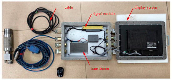
Figure 1.
Physical diagram of external electrical control equipment.
The device consists of a series of rod-shaped structural units with a total length of 7.5 m. The equipment casing is made of a 40CrMo steel rod, which is deep processed to form multiple tubular structures with a 90 mm diameter. Each tubular body forms a functional compartment. All functional units are sealed inside a tubular body. Its overall shell has a static pressure resistance of 30 MPa and an impact pressure resistance of >80 MPa. The main body of the drilling operation equipment, according to their respective functions, consists of the battery and communication compartment, energy storage capacitor, energy controller, and energy converter (including the load pusher), as shown in Figure 2.
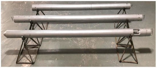
Figure 2.
Physical diagram of CSW drilling equipment.
The operational parameters of the CSW equipment, primarily the energy output per pulse and the pulse frequency, are regulated electronically. The surface control unit (Figure 1) allows operators to preset and adjust the discharge voltage and the firing sequence, which are transmitted to the downhole energy rods via the cable drill pipe. The fracturing mechanism begins with the instantaneous discharge within the sealed energy rod, generating a high-pressure plasma channel and a consequent controlled shock wave. This shock wave propagates through the coal mass as a stress wave. The induced dynamic tensile and shear stresses, upon exceeding the local tensile and shear strength of the coal, initiate fractures. Repeated pulses at a designated point cause cumulative damage, creating an interconnected fracture network that effectively weakens the hard top coal structure.
2.3.2. Design of Operation Process Parameters
We collected three coal-rock samples from the Liuxiang Coal Mine and conducted physical model testing of the mechanical performance in a laboratory. At the same time, on the basis of completing the shock wave energy screening experiment, the physical samples were subjected to shock crushing tests. We have determined to conduct large-scale on-site tests with 80 kJ energetic rods as the load. The initial operational parameters for the Leading group, specifically an impact point spacing of 5 m and a single-point impact frequency of 5, were determined based on preliminary laboratory shock crushing tests on the collected No. 3 coal samples, combined with empirical ranges suggested in prior engineering applications. This on-site test was then designed to systematically evaluate and optimize these parameters by gradually increasing the impact density (from 1 to 2 times/m) in subsequent test groups to enhance the fracture network while avoiding excessive structural damage. The design of CSW operation parameters is shown in Table 1.

Table 1.
Parameter design table for CSW pre-splitting hard coal operation technology in Liuxiang Coal Mine.
The 80 kJ energetic rod employs a rapid energy-release mechanism in which the propellant within the rod is instantaneously activated, generating high-pressure combustion gas that forms a steep-front shock wave that loads the borehole wall within milliseconds. After the device is triggered, the transient high-pressure event generates a shock wave with an initial pressure rise rate of 103–104 MPa/s, which acts directly on the inner wall of the borehole and induces radial tensile and shear stresses in the surrounding coal. The shock wave enters the coal body as a compressional wave and subsequently evolves into a mixed stress wave field due to the strong heterogeneity of the hard top coal. During propagation, part of the wave energy is consumed in the crack initiation, frictional slip, pore collapse, and micro-fracture activation. In contrast, the remaining energy attenuates through geometric dispersion, scattering at lithological interfaces, and viscous damping within microcracks. The combined effect produces localized high-strain zones near the borehole, progressive crack extension along weak planes, and stress-relief zones farther away. This energy-transmission mechanism explains the observed increase in coal fragmentation and the enhanced permeability detected during segmented water injection leakage evaluation in subsequent sections.
2.3.3. Test Drilling Design
To isolate and quantify the effect of CSW pre-cracking, a controlled comparison strategy was implemented within each drilling group. Specifically, for a given set of boreholes (e.g., the first group in the 30112 transport channel), one or more boreholes (e.g., DB1-1) were designated as pre-impact control holes. These control holes were drilled and subjected to segmented water injection leakage testing before any CSW treatment was applied to the adjacent area, establishing the baseline fracture condition and hydraulic conductivity of the intact coal seam. Subsequently, neighboring boreholes within the same geological block (e.g., SY1-1 for CSW treatment and G1-1 for post-treatment observation) were utilized for the fracturing operation and effect evaluation. The fundamental premise for a valid comparison is that all these boreholes (control and experimental) are located within the same, geologically uniform test area as detailed in Section 2.1. They share identical coal seam properties (thickness, hardness, and f-value), roof and floor lithology, and are subject to the same in situ stress field, ensuring that any significant difference in post-treatment observations (e.g., leakage rate in G1-1 vs. DB1-1) can be attributed to the CSW intervention rather than geological variation.
Based on the actual production at Liuxiang Coal Mine, this article has arranged four sets of test boreholes in the return air channel of the 30109 fully mechanized mining face and the transportation channel of the 30112 fully mechanized mining face. Specifically, a set of pilot test boreholes was arranged in the return air channel of the 30109 working face, totaling three. Three sets of large-scale verification test boreholes were placed along the transportation channel of the 30112 working face with 18 boreholes per set for a total of 54. The total number of test boreholes is 21, and the drilling parameter design is shown in Table 2.
Table 2.
Parameter design table for CSW pre-fracturing test drilling in Liuxiang Coal Mine.
The designed test drilling hole heights are all 1.8 m. The drilling is a double-opening structure, and the drilling trajectory must be controlled at 3 m/1°. The opening diameter is 153 mm, and the opening depth is at least 10 m. After opening, insert a 140 mm sealing tube for curing. The sealing pipe is made of PE, and the orifice is matched with a DN125 flange. The “two blockages and one injection” method is adopted for solidification. The secondary aperture is 133 mm to the final hole.
2.3.4. Effect Assessment Measures
The effectiveness evaluation measures in this article adopt an intuitive, quantitative approach to assess on-site test results.
- (a)
- For directly observable exposed areas, design a method for injecting chemical fluorescent agents and staining agents into the borehole for comprehensive tracking after drilling impact fracturing operations, which enables it to penetrate and contaminate the coal rock along the cracks generated by fracturing. After the working face is exposed, evaluate the cracking effect through fluorescence and staining.
- (b)
- For areas that cannot be directly observed in the deep, a dual-end sealing leak detector is used to quantitatively evaluate the development of coal fractures before and after impact pre-fracturing in the test area.
- (c)
- As an auxiliary means, observe and record the comprehensive production data of the mining face before and after entering the test area, such as the recovery rate, the size of coal blocks after the support, the condition of mining-face fragmentation, and the pressure step distance of the roof cycle.
2.3.5. Test Construction Procedure
The test construction procedure includes the following: (a) preparation before operation. (b) Controllable shock wave equipment drilling operation. (c) Fluorescent tracer deployment test. (d) Segmented water injection leak detection evaluation test. (e) Investigation of coal caving during backfilling.
3. Implementation of On-Site Tests
According to the implementation plan and the on-site testing plan, and in accordance with safety technical measures, 21 trial drilling operations were safely and efficiently completed in May 2023 and December 2023, respectively. The third-party evaluation team completed the segmented water injection leak testing during the same period. From February to March 2024, the testing group stationed at the site completed the full process disclosure and tracking of the test area.
3.1. Overview of the Implementation of the 30109 Return Air Trough Test Area
The project trial team entered on 7 May 2023. Due to the fact that the distance between the mining face of the 30109 fully mechanized caving face and the stopping line was only 170 m, in order to maximize the distance between the test area and the mining face, a test area was designated near the stopping line. Eight test boreholes were arranged with a spacing of 10 m and drilled. On 21–22 May, CSW testing operations were completed for three boreholes. After completing three consecutive impact tests on three boreholes, the CSW generation equipment worked normally. The drilling and sealing structure constructed is reliable. During the experiment, the orifice can achieve a pressure operation (0.5 MPa). After completing the impact test and fluorescence tracing for three boreholes, the remaining drilling operations on the working face were suspended due to frequent roof pressure on the 70~99# supports near the return air passage and the breakage of the top-coal roof. The site selection and drilling layout for the subsequent test boreholes in the transportation channel of the 30112 mining face were re-planned.
3.2. Overview of the Implementation of the 30112 Transportation Channel Test Area
According to the readjusted on-site testing plan, a total of 18 drilling operations were completed from 12 November to 30 November 2023 in the transportation channel test area of the 30112 working face. The CSW pre-cracking test was successfully completed from 7 December to 16 December. Due to the need to release the tracer after injection into the borehole, it is highly likely to contaminate the tunnel. Therefore, only the fourth group of SY3-5 and SY3-6 boreholes was injected with tracer. During the on-site testing at the Liuxiang Coal Mine, the CSW testing equipment operated stably, and the measures were implemented effectively. In accordance with the safe operation principle, four sets of 21 boreholes were completed in the designated test areas of the 30109 and 30112 working faces, verifying the feasibility of CSW technology and equipment for pre-cracking hard coal seams. By summarizing the drilling, auxiliary tools, and operational procedures during the on-site testing period, a preliminary CSW pre-cracking operation process specification has been developed. This establishes a foundation for subsequent large-scale experiments and applications.
3.3. Overview of Segmented Water Injection Leak Testing
To ensure the authenticity and objectivity of the evaluation of pre-fracturing effects, and to avoid the superposition effect of pre-fracturing between adjacent drilling groups, a group of shock wave pre-fracturing drilling holes is considered as a single observation object. According to the basic process of conducting comparative hole observation before pre-fracturing and then evaluating the effect after pre-fracturing, the on-site observation process was organized and implemented.
Due to strict on-site safety constraints and dynamic mining progress, it was not feasible to perform segmented water injection leakage testing repeatedly in the same borehole before and after CSW operations. To address this limitation, each drilling group was treated as an independent observation unit, and the comparative leakage tests were arranged in adjacent but non-overlapping boreholes before and after pre-fracturing. This design avoided mutual interference between drilling groups while ensuring that the evaluated changes in hydraulic conductivity were attributable solely to CSW-induced fracturing. Although this approach does not constitute an ideal same-hole before–after control, it represents the maximum feasible level of experimental control under the actual underground operating conditions.
4. Test Results and Discussions
4.1. Observation of Mining Face Before and After Impact Test
Before conducting the pre-cracking test on the 3# coal seam, coal-falling tracking observation and segmented water injection leakage evaluation were carried out in the two test areas on the 30109 and 30112 working faces, respectively. The results show that, before the CSW pre-cracking test, the overall coal-falling situation at the mining face was not ideal. The cutting end face is intact, and the support block size after coal placement is relatively large. After the pre-cracking test, cracks developed significantly in the borehole. The rate of large top-coal blocks within the test drilling influence range has decreased dramatically. After horizontal drilling is exposed, the cutting surface is broken, the slope is obvious, and the working face compression step is shortened.
4.1.1. Coal-Falling Situation in the 30109 Mining Face
During the suspension test of the 30109 return air channel, the testing team monitored and observed the mining conditions at the working face. During the exposure of the Y-1# drilling hole in the working face, the frequency of “coal firing gun sound” on the roof of the mining-face decreased. The top coal at the tail of the mining face machine shows fragmentation. The cutting end face of the coal mining machine is broken. The top-coal block size released by the bracket is about 50–80 cm. Affected by coal dust and lighting factors, no fluorescence was observed during the coal discharge period in the working face. After exposing drilling hole 2, a “roof leakage” phenomenon was observed near the 82# support. The top coal is relatively fragmented after being released. After the top coal is released from the front of the 78# bracket, it is relatively intact and has a larger block size. The roof of the top coal after the 80# support shows fragmentation.
4.1.2. Coal-Falling Situation in the 30112 Mining Face
Original coal bodies surround the 30112 working face transportation trough test area. Based on the on-site test, the f-value (Protodyakonov’s coefficient of rock strength) of the coal samples collected on site is approximately 2.5–3. The coal is hard, and the original cracks are not developed. The coal-cutting surface is complete. After the support coal is placed, the transfer machine is blocked by the large volume of lump coal, affecting the coal output efficiency. The length of the lump coal is about 1–2 m.
On January 2024, the 30112 working face entered the CSW pre-cracking test area. Starting from the same period, tracking and observation records have been conducted. As of 15 March, the 30112 fully mechanized mining face has completely pushed through the test area. Based on comparisons between the mining face and the drilling hole, as well as results of segmented sealing and leak testing, the 4~14# supports in the working face are CSW-affected areas. The impact range is approximately 20 m. For the sake of comparison, observation records were made during the observation period for brackets 0~3#, 15#, etc.
- (a)
- Observation of drilling holes in the first group of experiments
The 30112 fully mechanized mining face first exposed the second group of roof boreholes. Based on on-site observations, no significant changes were observed in this area. Visually, the top plate fragmentation is no different from that of the solid coal area. After the working face enters the top-coal drilling area, the coal-discharge situation at the rear of the mining-face support improved. The main manifestation is that the coal blocks released from the 3–7# supports are significantly reduced compared to before, and the coal release efficiency near the 1–7# supports is faster. The coal blocks released from brackets 7–15# are large, and the coal block rate after bracket 15# is relatively high. The coal is most fractured near the tail of the shearer and behind the support due to the stress concentration.
- (b)
- Observation of drilling holes in the second group of experiments
During the second drilling period, the 30112 working face revealed an increase in the cutting surface fragmentation. Before the shearer cuts and after the front guard plate of the support is retracted, the coal wall often peels off in large pieces, and the corresponding coal body at the drilling height is broken.
- (c)
- Observation of drilling holes in the third group of experiments
During the exposure period of the third group of boreholes, the coal seam fragmentation and cutting surface improved significantly, with greater fragmentation. This relates to the higher-intensity impact operations used in the fourth group of boreholes.
Further observation of the goaf reveals that, except for the coal seam at the top of the transportation roadway in the 30112 fully mechanized caving face, which is difficult to collapse, the 2# support and the subsequent roof can all collapse well. Although the degree of falling blocks is relatively large, the number of visible sandstone blocks and sandstones in the goaf is higher than those in the aforementioned two groups.
According to the mining technology at the Liuxiang Coal Mine, high-pressure water injection boreholes need to be constructed at the top of the transportation channel before mining the working face. During the injection of water into the borehole, there was a significant water outflow phenomenon in the top coal borehole located on the coal wall. Once the injection is stopped, the water output from the shock wave pre-fracturing borehole also decreases, and coal wall seepage within the pre-fracturing borehole range is significant.
Preliminary statistics were conducted on the large coal blocks released. When observing the coal discharge in the test area and non-test area within a fixed time, the coal blocks with a block size of ≥1 m are counted. In an hour, 45 large blocks of coal were released near the 45–25# supports in the working face far from the test area. A total of 34 large blocks were released from the 24# bracket near the test area to the head of the transfer machine. In comparison, the production of large coal blocks in the test area decreased by about 25% compared to solid coal without impact.
Based on the above observations, a preliminary quantitative correlation was established between the CSW operational parameters and the pre-splitting effects. As the impact density increased from 1.0 times/m in the Leading group to 1.6 times/m and 2.0 times/m in the first and second groups, respectively, the leakage intensity measured in segmented water injection tests increased by approximately 18% and 31%, respectively, within the corresponding influence range. This enhancement in leakage is consistent with the observed development of borehole fractures and reflects the improved connectivity of pre-split cracks. Meanwhile, the number of large coal blocks (≥1 m) released per hour decreased from an average of 45 blocks in the non-test area to 34 blocks within the impact zone under an impact density of about 2.0 times/m, representing a reduction of approximately 25%. During the exposure of the third group of boreholes, where the effective impact intensity was highest, the cutting-face fragmentation increased noticeably, indicating that the cumulative effect of higher-density impacts promoted further propagation of microcracks. Production data from the 30112 working face also shows that, after entering the CSW influence zone, the roof pressure step distance decreased from the baseline range of 16.12–20.03 m to 13.12–13.82 m, representing a reduction of about 15–25%, which corresponds well with the higher degree of pre-splitting in the higher-density operation areas. These quantitative trends demonstrate that an increase in impact density is positively correlated with improved fracture development, enhanced permeability, reduced block-size coal, and decreased roof step distance, providing a more explicit basis for optimizing CSW pre-splitting parameters.
4.2. Production Data Analysis of 30112 Working Face
To evaluate the influence of CSW pre-cracking on roof behavior, monthly mining pressure records from the 30112 working face were collected from November 2023 to March 2024. As shown in Table 3, during this time, the face completed a total of 867.6 coal-cut cycles, averaging 216.9 cycles per month, and 45 roof pressure events were documented. The average roof pressure step distance for the entire dataset was 15.43 m, with an average duration of 10.97 h.
Table 3.
Statistical table of mining pressure manifestation in the 30112 working face.
Before entering the CSW test area (November–December 2023), the recorded roof pressure step distances ranged between 16.12 m and 20.03 m. In November 2023, the average step distance was 20.03 m, with an average duration of 13.42 h; events were mostly concentrated between supports 38–52#. In December 2023, the average step distance was 16.12 m, and the average duration was 1.28 h; events mainly occurred near support 35#.
After the mining face advanced into the CSW test area (January–March 2024), the monitored roof behavior changed noticeably. In January 2024, the average step distance decreased to 13.12 m and the average duration to 9.78 h, with most events concentrated near support 28#. From 15 February to 16 March 2024, the average step distance was 13.82 m, and the average duration was 13.62 h, with events mainly occurring near support 33#.
The statistical data on roof pressure events, shown in Figure 3, reveal a distinct change in strata behavior associated with CSW pre-cracking. Before the working face entered the CSW test area (November–December 2023), the roof pressure step distance ranged from 16.12 m to 20.03 m. A clear reduction occurred as mining advanced into the pre-conditioned zone (January–March 2024), with the step distance decreasing to 13.12–13.82 m, representing a reduction of approximately 15–25%. This significant shortening indicates that the CSW-induced fracture network effectively weakened the hard top coal and immediate roof, leading to more frequent but less severe (shorter step) roof weighting cycles. The slight increase in step distance observed later in the test period (from 13.12 m in January to 13.82 m in February–March, as seen in Figure 3) does not signify a full return to the pre-test baseline. Rather, it likely reflects the spatial heterogeneity of the fracturing effect or a gradual transition as the face moves beyond the zone of most intensive pre-cracking. Crucially, the post-CSW distances remained consistently and substantially below the initial 16.12–20.03 m range, confirming a sustained modifying effect on roof behavior within the treated section. Furthermore, the pressure events became more spatially concentrated near the test boreholes (e.g., around supports 28# and 33#), correlating directly with the locations of CSW operations.
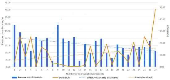
Figure 3.
Statistical chart of the main roof pressure events and pressure step distance of the 30112 working face.
The test influence area along the 30112 working face was less than 40 m compared with the total face length of 196 m. Because the CSW-treated section occupied only a small portion of the face, daily production and overall recovery rate were still mainly governed by regular mining processes, equipment operating conditions, and human interventions. As a result, the observed changes in production indicators were not significant on the whole-face scale. Nevertheless, within the affected zone, reductions in the step distance of the roof pressure and improvements in coal fragmentation behavior demonstrate that CSW operations effectively weaken hard coal seams. These findings are reliable for the tested section but should be interpreted cautiously when extrapolating to full-length mining conditions. Future industrial-scale tests over longer distances will be needed to validate production improvements further and optimize operational parameters.
4.3. Evaluation of Segmented Plugging and Leak Detection in Drilling
In this part, the evaluation and analysis of the segmented plugging of drilling holes in the first group of experiments are presented. To quantitatively evaluate the effectiveness of the CSW pre-cracking, the DB1-1 borehole was designated as the control or benchmark borehole. It was drilled in the same test area under identical geological conditions but was not subjected to any CSW treatment. The water injection leakage data and the inferred fracture development state obtained from DB1-1 thus represent the baseline, pre-treatment condition of the intact hard top coal. The performance of CSW in the treated boreholes (e.g., G1-1, G1-2) is assessed by directly comparing their post-treatment leakage rates and fracture zone characteristics against this established DB1-1 benchmark.
- (a)
- Analysis of Water Leakage Data in DB1-1 Drilling
On December 1, segmented sealing and water injection leakage were observed in the DB1-1 borehole, starting from a hole depth of 11 m and ending at a hole depth of 39 m (with a sealing hole section length of 1 m). The water pressure during the observation was stable and exceeded 1 MPa. Due to low wind pressure on the site, the double-end water-blocking device used water injection to inflate the capsule. The capsule bulged normally, and the sealing effect was good. The first set of the DB1-1 borehole water injection leakage records is shown in Table 4. Note that the numbering of the drill pipes starts from 9 because drill pipes 1–8 correspond to the 0–10 m casing consolidation section, which is not part of the leakage measurement interval.
Table 4.
The first set of DB1-1 drilling water injection leakage records.
The distribution of leakage in each hole section of the DB1-1 borehole is shown in Figure 4. Analysis shows that the leakage rate in DB1-1 drilling is generally low, less than 1 L/min, with an average of 0.15 L/min. Among them, the maximum leakage measured in the observation hole section at a depth of 27 m was 0.76 L/min. The leakage rate measured at the depths of 15 m, 19 m, 23 m, 25 m, 31 m, 33 m, 35 m, and 39 m was 0 L/min. The DB1-1 borehole is a pre-fracturing comparison hole, and the development of primary fractures in the coal-rock mass can be evaluated by observing water injection leakage. Based on the above analysis, it can be concluded that the top-coal, direct-top, and old-top structures of the 30112 fully mechanized caving face are intact, with no primary or undeveloped cracks.
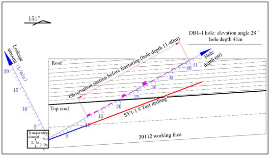
Figure 4.
Analysis results of segmented water injection leakage in DB1-1 borehole.
- (b)
- Analysis of G1-1 borehole water injection leakage data
On December 23, segmented sealing and water injection leakage observation were conducted on the G1-1 borehole, starting from a hole depth of 21 m and ending at a hole depth of 39 m. The first group of G1-1 borehole water injection leakage records is shown in Table 5.
Table 5.
The first group of G1-1 drilling water injection leakage records.
Based on the observation data of the G1-1 borehole, with the depth of the borehole as the horizontal axis and the water injection leakage amount in the sealed borehole section as the vertical axis, the distribution map of the leakage amount in each borehole section of the G1-1 borehole is obtained, as shown in Figure 5. From Figure 5 it can be seen that, from the overall analysis of the distribution pattern of the leakage amount in each measurement section, it is obvious that there is a clear zoning phenomenon of leakage amount in each measurement section along the drilling axis, namely, Zone I, Zone II, and Zone III. Among them, Zone I corresponds to a hole depth of 21 m~29 m (the length of the sealed hole section is 1 m). The leakage amount of the hole segment measured in this area is relatively small, ranging from 0.13 to 0.96 L/min. The leakage amount of each hole segment in this area has not changed much compared to the corresponding hole segment in DB1-1 drilling before pre-splitting. The integrity of the surrounding rock structure is good. The fissure is undeveloped and belongs to the shallow original rock area. Zone II corresponds to a hole depth of 29 m to 34 m. The leakage rate of each hole segment in this area is between 3.92 and 3.26 L/min. It is significantly larger than the corresponding hole segment of the DB1-1 borehole before pre-fracturing and exhibits the characteristic of being high in the front and low in the back. This is obviously related to the location of the SY1-1 borehole impact point. It can be determined that Zone II is the impact pre-cracking zone. Zone III corresponds to a hole depth of 34 m to 40 m. The leakage amount from each hole segment in this area is significantly lower than in Zone II. Similarly to Zone I, located at 0.1–0.36 L/min, there is not much change in the leakage amount of the corresponding hole segment of DB1-1 drilling before pre-fracturing. The integrity of the surrounding rock structure is good, and the cracks are not developed, forming a deep original rock area. Analysis suggests that the impact pre-cracking radius formed by each impact point in the SY1-1 borehole is limited. The inclination angles of the G1-1 borehole (28°) and SY1-1 borehole (20°) are different. As the hole depth increases, the vertical distance between the two gradually increases. The impact of impact pre-cracking will gradually decrease until it completely separates from the impact pre-cracking zone and enters the deep original rock zone.
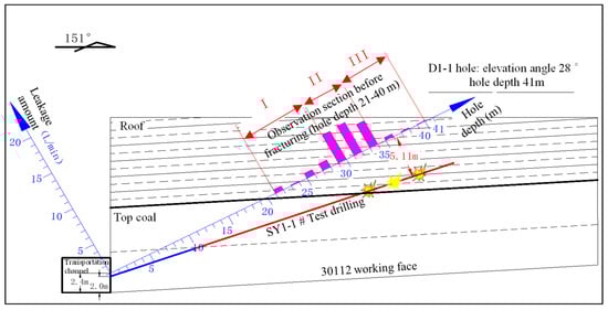
Figure 5.
Analysis results chart of G1-1 borehole segmented water injection leakage rate.
- (c)
- Analysis of G1-2 drilling water injection leakage data
On 23 December, observation of segmented sealing and water injection leakage was conducted in the G1-2 borehole, starting from a hole depth of 21 m and ending at a hole depth of 39 m (with a sealing hole section length of 1 m). The entire observation process must be conducted strictly in accordance with the relevant technical requirements. The water pressure is stable and greater than 1 MPa. The wind pressure is stable and greater than 0.5 MPa. The swelling pressure of the double-end water blocking device capsule is 0.5~0.6 MPa. The capsule bulges normally and provides a good seal. The first group of the G1-2 borehole water injection leakage records is shown in Table 6.
Table 6.
The first group G1-2 drilling water injection leakage records.
Based on the observation data of the G1-2 borehole, with the depth of the borehole as the horizontal axis and the water injection leakage amount in the sealing hole section as the vertical axis, the distribution of the leakage amount in each hole section of the G1-2 borehole is obtained, as shown in Figure 6. From Figure 6 it can be seen that the overall analysis of the distribution pattern of the leakage amount in each measurement section is similar to that of the G1-1 borehole. It can clearly be seen that there is a clear zoning phenomenon in the leakage amount of each measurement section along the drilling axis, namely, Zone I, Zone II, and Zone III. Among them, Zone I corresponds to a hole depth of 19 m~21 m (the length of the sealed hole section is 1 m). The leakage from the hole segment in this area is relatively small at only 0.4 L/min. The leakage amount of each hole segment in this area has not changed much compared to the corresponding hole segment in DB1-1 drilling before pre-splitting. The integrity of the surrounding rock structure is good, and the cracks are not developed, which is a shallow original rock area [40]. Zone II corresponds to a hole depth of 21 m to 24 m. The leakage rate of each hole segment in this area is between 3.81 and 4.29 L/min. It is significantly larger than the corresponding hole segment of the DB1-1 borehole before pre-fracturing and exhibits the characteristic of being high in the front and low in the back. This is obviously related to the location of the impact point in the SY1-3 borehole. It can be determined that Zone II is the impact pre-cracking zone. Zone III corresponds to a hole depth of 24–40 m. The leakage amount from each hole segment in this area is significantly lower than in Zone II.
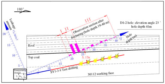
Figure 6.
Analysis results chart of G1-2 drilling segmented water injection leakage rate.
Similarly to Zone I, located at 0.1–0.57 L/min, there is not much change in the leakage amount of the corresponding hole segment of DB1-1 drilling before pre-fracturing. The integrity of the surrounding rock structure is good, and the cracks are not developed, forming a deep original rock area. Analysis suggests that the impact pre-cracking radius formed by each impact point in the SY1-3 boreholes is limited. The inclination angles of the G1-2 borehole (23°) and SY1-3 borehole (12°) are different. As the hole depth increases, the vertical distance between the two gradually increases. The impact of impact pre-cracking will gradually decrease until it completely separates from the impact pre-cracking zone and enters the deep original rock zone.
4.4. Discussions
The field observations and production data collectively demonstrate that the mechanical response of hard top coal to CSW loading is governed by a dynamic fracturing mechanism driven by high-energy stress wave propagation. The progressive improvements observed in borehole crack development, coal-wall fragmentation, reduction in large coal blocks, and the shortening of roof pressure step distance indicate that the shock-wave loading (80 kJ per pulse) generated by the energy bar produces a coupled tensile–shear failure regime in the No. 3 coal seam. When the CSW device is activated, the rapid release of high-amplitude stress waves leads to localized stress concentration near the borehole wall, inducing tensile spalling and microcrack initiation. As the stress wave propagates outward, its energy is partially transmitted and partially attenuated through interactions with the specific mechanical heterogeneities and strength properties of the hard No. 3 coal seam, consistent with established wave-propagation theory in porous media [25,26,30,31,32,33]. The observed zoning of fracture effectiveness (Figure 5 and Figure 6) and the limited pre-cracking radius are direct manifestations of this property-dependent attenuation. The increase in impact density in subsequent test groups facilitated the coalescence of microcracks generated in earlier cycles, forming a more continuous fracture network. This cumulative effect explains both the observed enhancement in leak-off intensity during segmented water injection evaluation and the increased fragmentation of the coal wall during mining.
The mechanisms identified in this study align with the findings of previous laboratory and theoretical research. Earlier works demonstrated that CSW-induced fracturing efficiency depends strongly on coal pore structure evolution, crack propagation characteristics, and sensitivity to shock loading [7,8,9,10,11,12,13,14]. The present field-scale observations verify these mechanisms under in situ conditions, showing that, as in laboratory-scale results, dynamic loading effectively promotes the initiation and extension of fractures in hard coal bodies with initially low porosity and poor permeability. Moreover, the attenuation behavior of the shock wave observed in the field—where increased impact density compensates for energy dissipation in the coal mass—corresponds well with the documented dependencies of stress wave amplitude on the crack length, interface stiffness, and fluid–solid interactions in saturated porous media [34,35,36,38,39]. This consistency reinforces the applicability of wave-based fracture theories to field CSW operations.
In addition, the roof pressure response in the 30112 working face provides important insight into the interaction between CSW-induced fractures and the overlying strata’s stress field. After the mining face entered the CSW-influenced zone, the roof pressure step distance decreased by approximately 15–25%, and pressure events became more concentrated spatially. This behavior is consistent with mine pressure theory, wherein the weakening of a hard roof layer reduces periodic energy release and leads to earlier, less violent weighting. Comparable observations have been reported in studies examining dynamic preconditioning and shock-assisted cavability enhancement, which noted that dynamic impacts can effectively reduce roof stiffness, alter stress redistribution patterns, and promote controlled caving. The present field results, therefore, extend previous studies by demonstrating that CSW not only increases coal cavability but also modifies roof mechanical behavior on the working-face scale.
Throughout this study, the mechanical properties of the hard top coal from the Liuxiang Mine (e.g., its high strength and low initial permeability) were a primary consideration. The optimization of CSW parameters (Table 1)—such as reducing impact point spacing and increasing impact density—was a direct response to the anticipated high energy attenuation rate in this competent medium. The field results confirm that this tailored parameter design successfully compensated for the strong attenuation, enabling the creation of an effective fracture network. This underscores the principle that successful CSW application requires the operational parameters to be calibrated against the target coal-rock’s mechanical characteristics.
A comprehensive set of field-based indicators guided the optimization process in this study: (1) the degree of fracture development, quantitatively reflected by the increase in the segmented water injection leakage rate; (2) the improvement in top-coal cavability, measured by the reduction in the proportion of large coal blocks (≥1 m); and (3) the positive modification of roof behavior, indicated by the reduction in roof pressure step distance. By systematically comparing the effects of the three parameter sets in the Leading, first, and second groups (Table 1), a clear trend emerged: the impact density (times/m) showed a strong positive correlation with improvements across all three indicators. While the first group (1.6 times/m) showed significant improvement over the Leading group (1.0 times/m), the second group (2.0 times/m) delivered the most balanced and effective results, achieving the highest leakage increase (~31%), a substantial 25% reduction in large blocks, and the most pronounced shortening of the roof step distance (~15–25%). Therefore, based on this multi-criteria field evaluation, the parameter set corresponding to an impact density of 2.0 times/m—specifically, an impact point spacing of 3 m and a single-point impact frequency of 6—is identified as the optimized configuration for pre-cracking the hard top coal under the geological conditions of the Liuxiang Mine’s No. 3 seam. This configuration effectively compensates for the high-energy attenuation while creating a sufficiently dense, connected fracture network.
The quantified improvements have direct and significant implications for mining economics and safety. The ~25% reduction in oversized coal blocks translates to reduced clogging at support outlets and transfer points, leading to smoother material flow, lower equipment wear and tear, less downtime for blockage clearance, and, consequently, higher effective production efficiency. Simultaneously, the 15–25% reduction in the step distance of the roof pressure indicates a fundamental shift towards more manageable strata behavior. Shorter, more frequent weighting cycles are typically less violent and more predictable, reducing the risk of dynamic failure and enhancing the safety of personnel and support systems. Together, these metrics demonstrate that CSW pre-cracking not only alters the physical state of the coal and roof but also delivers tangible operational benefits by making the mining process more efficient and safer.
Compared with the existing literature, this study provides two primary contributions.
First, unlike earlier works mainly focused on laboratory-scale pore structure evolution, crack initiation, or permeability adjustment under shock loading [7,8,9,10,11,12,13,14], the present research verifies these mechanisms under actual mining conditions and quantifies their influence on coal fragmentation and roof behavior.
Second, studies on geological constraints affecting CSW effectiveness have primarily emphasized coal seam characteristics, stress environments, and fluid conditions [31,32,33,34,35,36]. However, research specifically addressing hard top-coal pre-cracking remains scarce. The results of this study fill this gap by showing that the appropriate control of impact spacing, frequency, and density can produce measurable changes in fracture development and roof-pressure response, thereby providing an empirical basis for optimizing CSW parameters in hard-roof mining scenarios.
Overall, the findings confirm that the coupled effects of stress wave propagation, fracture coalescence, and stress-field redistribution govern CSW-induced pre-cracking in hard top coal. The interplay of these mechanisms explains the improvements observed in coal fragmentation, permeability indicators, and roof behavior. These results not only support the theoretical framework established in prior studies but also provide new field-scale evidence for advancing the engineering application of CSW technology in complex hard-roof conditions.
5. Conclusions
This study conducted field tests on the controllable shock wave (CSW) pre-cracking technology at the Liuxiang Coal Mine, with the experimental zone spanning a representative 40 m section of the 196 m-long 30112 working face. To ensure experimental integrity, a segmented plugging and leak-detection protocol was rigorously applied. The research established optimized CSW operating parameters for the local hard top-coal conditions and yielded the following primary results:
- (a)
- Effective Fracture Initiation and Improved Cavability: The optimized CSW parameters successfully initiated dense fracture networks within the hard top coal. Field observations confirmed a significant enhancement in cavability, evidenced by a ~25% reduction in the proportion of large coal blocks, which directly translates to higher recovery efficiency and lower energy consumption for secondary handling.
- (b)
- Enhanced Roof Stability and Stress Management: CSW pre-cracking effectively reduced the roof pressure step distance from 16.12–20.03 m to 13.12–13.82 m. This demonstrates the technology’s capacity to weaken the hard roof structure, redistribute stress concentrations, and promote more controlled and predictable caving cycles, thereby enhancing operational safety.
- (c)
- Validation of an Integrated Field Methodology: The study validates a practical field methodology combining reliable borehole sealing (via segmented plugging and leak detection) with optimized CSW loading. The cumulative effect of multiple CSW impact points across the working face proved to be effective at improving overall mining conditions.
- (d)
- Identification of Applicability Limits: This study also helps delineate the applicability boundaries of CSW technology. Its effectiveness is contingent upon several key conditions: (1) the target coal-rock mass should possess sufficient brittleness to facilitate tensile and shear fracture initiation under dynamic loading; (2) boreholes must be constructable with adequate integrity for proper sealing to contain the shock wave energy; and (3) the geological setting should allow for the implementation of the designed borehole layout without major disruptions from intense tectonic structures or extreme groundwater inflow. The technology may be less effective in highly plastic, heavily fractured, or deeply weathered strata, where energy attenuation is excessive and fracture coalescence is limited.
The findings and optimized parameters are directly validated for the specific geological and mining conditions of the Liuxiang Coal Mine. Regarding broader applicability, the fundamental engineering mechanisms—controlled shock waves to induce fractures and redistribute stress in hard, brittle coal-rock masses—are universally applicable. However, successful application at other sites would require site-specific adjustments to the CSW loading parameters (e.g., pressure, pulse duration) based on local rock mechanical properties, in situ stress fields, and borehole layout. The core methodology, including the critical step of borehole integrity verification, remains broadly transferable. While the optimized parameters are validated for a specific geological block and a limited face length, this study provides a foundational and field-verified parameter range (e.g., impact density of ~2.0 times/m) and a robust methodological framework essential for planning and executing larger-scale industrial trials, which are the logical next step towards full-face implementation.
In summary, this research provides a field-verified framework and mechanistic understanding for CSW pre-cracking technology. It highlights the importance of integrated engineering practices—from borehole preparation to parameter optimization—for achieving predictable improvements in top-coal cavability and roof stability in hard-rock mining environments.
Author Contributions
Conceptualization, A.S., Y.L., Y.Z., J.Z., S.Z., L.L., H.D. and W.C.; methodology, A.S.; writing—original draft preparation, A.S., Y.L., Y.Z., J.Z., S.Z., L.L., H.D. and W.C.; writing—review and editing, A.S. and Y.Z.; visualization, A.S.; supervision, A.S.; project administration, A.S. All authors have read and agreed to the published version of the manuscript.
Funding
This paper was funded by China Huaneng Group Headquarters Technology Project “Experimental Study on Controlled Shock-wave Pre-splitting Hard Top Coal in Liuxiang Coal Mine” (HNKJ21-HF09).
Data Availability Statement
The data are contained within the article.
Acknowledgments
The authors have reviewed and edited the output and take full responsibility for the content of this publication.
Conflicts of Interest
Authors Aiguo Shi, Jinjin Zhang and Hang Du were employed by the Shanxi Zhuyuan Jiayuan Mining Company. Authors Yongyuan Li and Lei Li were employed by the Huaneng Coal Technology Research Co., Ltd. The remaining authors declare that the research was conducted in the absence of any commercial or financial relationships that could be construed as a potential conflict of interest.
References
- Cho, S.; Cheong, S.; Yokota, M. The Dynamic Fracture Process in Rocks Under High-Voltage Pulse Fragmentation. Rock Mech. Rock Eng. 2016, 49, 3841–3853. [Google Scholar] [CrossRef]
- Kafashi, S.; Kuhar, L.; Bóna, A.; Nikoloski, A. Review of Fracturing Techniques (Microwaves, High-Voltage Pulses, and Cryogenic Fluids) for Application as Access Creation Method in Low-Permeability Hard Rocks for Potential in situ Metal Recovery. Miner. Process. Extr. Metall. Rev. 2023, 45, 522–537. [Google Scholar] [CrossRef]
- Selyutina, N.; Petrov, Y. Fracture of saturated concrete and rocks under dynamic loading. Eng. Fract. Mech. 2020, 225, 106265. [Google Scholar] [CrossRef]
- Wei, C.; Li, S.; Yu, L. Study on Mechanism of Strength Deterioration of Rock-Like Specimen and Fracture Damage Deterioration Model Under Pulse Hydraulic Fracturing. Rock Mech. Rock Eng. 2023, 56, 4959–4973. [Google Scholar] [CrossRef]
- Xi, X.; Yang, S.; McDermott, C. Modelling Rock Fracture Induced By Hydraulic Pulses. Rock Mech. Rock Eng. 2021, 54, 3977–3994. [Google Scholar] [CrossRef]
- Matin, P.; Bruce, G.; Robert, G. Dynamic hydraulic stimulation and fracturing from a wellbore using pressure pulsing. Eng. Fract. Mech. 2022, 235, 107152. [Google Scholar] [CrossRef]
- Wang, S.; Liu, W.; Li, Y.; Zhang, L.; Liang, Y.; Liu, X.; Pu, S.; Liang, Y.; Liu, S. Numerical Simulation of Fracture Propagation and Damage Evolution in Coal Seam Under Controlled High-Energy Shock Wave Fracturing. Appl. Sci. 2025, 15, 12279. [Google Scholar] [CrossRef]
- Zhao, Y.; Zhang, L.; Wang, W.; Tang, J.; Lin, H.; Wan, W. Transient pulse test and morphological analysis of single rock fractures. Int. J. Rock Mech. Min. Sci. 2017, 91, 139–154. [Google Scholar] [CrossRef]
- Ni, Z.; Lin, B.; Zhang, X.; Cao, X.; Zhong, L.; Gao, Y. Experimental study on the effect of high-voltage electrical pulses on the nanoscale pore structure of coal. Fuel 2021, 306, 121621. [Google Scholar] [CrossRef]
- Li, Q.; Lin, B.; Zhai, C. The effect of pulse frequency on the fracture extension during hydraulic fracturing. J. Nat. Gas Sci. Eng. 2014, 21, 296–303. [Google Scholar] [CrossRef]
- Hou, P.; Gao, F.; Ju, Y.; Cheng, H.; Gao, Y.; Xue, Y.; Yang, Y. Changes in pore structure and permeability of low permeability coal under pulse gas fracturing. J. Nat. Gas Sci. Eng. 2016, 34, 1017–1026. [Google Scholar] [CrossRef]
- Feng, W.; Rao, P.; Nimbalkar, S.; Chen, Q.; Cui, J.; Ouyang, P. The Utilization of a Coupled Electro-Thermal-Mechanical Model of High-Voltage Electric Pulse on Rock Fracture. Materials 2023, 16, 1693. [Google Scholar] [CrossRef]
- Liu, X.; Duan, L.; Li, C. Simulation and Experimental Study on the Rock-Breaking Process Induced by High-Voltage Electric Pulse. Rock Mech. Rock Eng. 2024, 57, 6141–6161. [Google Scholar] [CrossRef]
- Yin, T.; Liu, C.; Chen, Y.; Zhuang, D.; Wu, Y.; Dai, H.; Su, J. Experimental and numerical study on the facture behavior of heated-granite subjected to high-voltage electric pulse. Eng. Fract. Mech. 2024, 299, 109935. [Google Scholar] [CrossRef]
- Ezzat, M.; Börner, J.; Kammermann, B. Impact of Temperature on the Performance of Plasma-Pulse Geo-Drilling (PPGD). Rock Mech. Rock Eng. 2024, 57, 3531–3542. [Google Scholar] [CrossRef]
- Lai, S.; Huang, F.; Chen, K.; Liu, Y.; Li, B.; Jin, F.; Zhang, J.; Qi, Y. Experimental study on pulsed pneumatic pre-fracturing grouting in sandy and clayey-silty hydrate-bearing sediments. Gas Sci. Eng. 2024, 126, 205338. [Google Scholar] [CrossRef]
- Li, H.; Huang, B.; Han, X.; Wu, Z.; Li, H.; Zhao, X. Pulse effects on proppant transport and dune shape in vertical fracture applied in coalbed methane mining engineering during the pulse hydraulic fracturing. Geoenergy Sci. Eng. 2023, 229, 212128. [Google Scholar] [CrossRef]
- Shi, C.; Pian, J.; Zhang, C.; Chen, X.; Zhang, Y. Numerical study on rock fracturing with pulsed pressure in hard rocks with a pipe-domain seepage model. Simul. Model. Pract. Theory 2024, 130, 102860. [Google Scholar] [CrossRef]
- Soliman, M.Y.; Rezaei, A.; Khalaf, M.; Gordon, P.; Cipolla, C. Pulse power plasma stimulation: A technique for waterless fracturing, enhancing the near wellbore permeability, and increasing the EUR of unconventional reservoirs. Gas Sci. Eng. 2024, 122, 205201. [Google Scholar] [CrossRef]
- He, P.; Lu, Z.; Lu, Y.; Huang, Y.; Pan, L.; Ouyang, L.; Zhou, J. Experimental study on fracture propagation and induced earthquake reduction by pulse hydraulic fracturing in shale reservoirs. Gas Sci. Eng. 2023, 110, 204908. [Google Scholar] [CrossRef]
- Ghazaryan, K.; Piliposyan, D.; Piliposian, G. Reflection and transmission of shear elastic waves through periodically stratified piezoelectric reflector with imperfect interfaces. Int. J. Solids Struct. 2025, 321, 113514. [Google Scholar] [CrossRef]
- Guo, L.; Zhang, N.; Yu, Y.; Xu, W.; Gao, L.; Hou, X.; Chen, S.; Wu, S.; Tian, F. Pulse Pressure Variability and the Risk of Fragility Fracture: The Kailuan Prospective Cohort Study in China. Bone 2023, 173, 116776. [Google Scholar] [CrossRef] [PubMed]
- Yu, X.; Chen, A.; Hong, L.; Zhai, C.; Regenauer-lieb, K.; Sang, S.; Xu, J.; Jing, Y. Experimental investigation of the effects of long-period cyclic pulse loading of pulsating hydraulic fracturing on coal damage. Fuel 2024, 358, 129907. [Google Scholar] [CrossRef]
- Shen, H.; Yong, H.; Zhou, Y. Modelling of dynamic fracture in bulk superconductor during pulsed field magnetization using ordinary state-based peridynamics. Eur. J. Mech.-A/Solids 2024, 103, 105138. [Google Scholar] [CrossRef]
- Wang, Y.; Li, X.; Zhao, B.; Zhang, Z. 3D numerical simulation of pulsed fracture in complex fracture-cavitied reservoir. Comput. Geotech. 2020, 125, 103665. [Google Scholar] [CrossRef]
- Lin, Y.; Ma, J.; Lai, Z.; Huang, L.; Lei, M. A FDEM approach to study mechanical and fracturing responses of geo-materials with high inclusion contents using a novel reconstruction strategy. Eng. Fract. Mech. 2023, 282, 109171. [Google Scholar] [CrossRef]
- Xue, Y.; Liu, S.; Chai, J.; Liu, J.; Ranjith, P.G.; Cai, C.; Gao, F.; Bai, X. Effect of water-cooling shock on fracture initiation and morphology of high-temperature granite: Application of hydraulic fracturing to enhanced geothermal systems. Appl. Energy 2023, 337, 120858. [Google Scholar] [CrossRef]
- Xue, Y.; Ranjith, P.G.; Gao, F.; Zhang, Z.; Wang, S. Experimental investigations on effects of gas pressure on mechanical behaviors and failure characteristic of coals. J. Rock Mech. Geotech. Eng. 2023, 15, 412–428. [Google Scholar] [CrossRef]
- Wu, Q.; Liu, Y.; Tang, H.; Kang, J.; Wang, L.; Li, C.; Wang, D.; Liu, Z. Experimental study of the influence of wetting and drying cycles on the strength of intact rock samples from a red stratum in the Three Gorges Reservoir area. Eng. Geol. 2023, 314, 107013. [Google Scholar] [CrossRef]
- Liu, X.; Yan, P.; Zhu, J.; Yang, X.; Zhang, X.; Zhou, C.; Lu, W.; Chen, M.; Wang, G.; Wang, Y. Effect of Neighboring Hole Impacts on Inter-Hole Dynamic Presplitting Process with Consideration of Crack Width Variations. Appl. Sci. 2025, 15, 10036. [Google Scholar] [CrossRef]
- Ge, Z.; Zhang, H.; Zhou, Z.; Cao, S.; Zhang, D.; Liu, X.; Tian, C. Experimental study on the characteristics and mechanism of high-pressure water jet fracturing in high-temperature hard rocks. Energy 2023, 270, 126848. [Google Scholar] [CrossRef]
- Xin, J.; Jiang, Q.; Li, S. Fracturing and Energy Evolution of Rock Around Prefabricated Rectangular and Circular Tunnels Under Shearing Load: A Comparative Analysis. Rock Mech. Rock Eng. 2023, 56, 9057–9084. [Google Scholar] [CrossRef]
- Zhang, Y.; Zhao, Y.; Zang, A. Acoustic Emission Evolution and Hydraulic Fracture Morphology of Changning Shale Stressed to Failure at Different Injection Rates in the Laboratory. Rock Mech. Rock Eng. 2024, 57, 1287–1308. [Google Scholar] [CrossRef]
- Ma, Q.; Liu, X.; Tan, Y.; Elsworth, D.; Shang, J.; Song, D.; Liu, X.; Yan, F. Numerical study of mechanical properties and microcrack evolution of double-layer composite rock specimens with fissures under uniaxial compression. Eng. Fract. Mech. 2023, 289, 09403. [Google Scholar] [CrossRef]
- Liu, J.; Mei, L.; Ding, W.; Xu, K.; Yang, H.; Liu, Y. Asymmetric propagation mechanism of hydraulic fracture networks in continental reservoirs. GSA Bull. 2022, 135, 678–688. [Google Scholar] [CrossRef]
- Wu, L.; Hou, Z.; Luo, Z.; Xiong, Y.; Zhang, N.; Luo, J.; Fang, Y.; Chen, Q.; Wu, X. Numerical simulations of supercritical carbon dioxide fracturing: A review. J. Rock Mech. Geotech. Eng. 2023, 5, 1895–1910. [Google Scholar] [CrossRef]
- GB/T 23561: 2024; Methods for Determining the Physical and Mechanical Properties of Coal and Rock. State Administration for Market Regulation: Beijing, China, 2024.
- Duan, Z.; Zhang, Y.; Yang, F.; Liu, M.; Wang, Z.; Zhao, Y.; Ma, L. Research on controllable shock wave technology for in-situ development of tar-rich coal. Energy 2024, 288, 129706. [Google Scholar] [CrossRef]
- Zhang, J.-Y.; Gong, Y.-X. Study on anti-reflection of deep soft and high gas coal seam floor by deep hole controlled blasting. Sci. Rep. 2024, 14, 25720. [Google Scholar] [CrossRef]
- Yao, Q.-L.; Xu, Q.; Liu, J.-F.; Zhu, L.; Li, D.-W.; Tang, C.-J. Post-mining failure characteristics of rock surrounding coal seam roadway and evaluation of rock integrity: A case study. Bull. Eng. Geol. Environ. 2021, 80, 1653–1669. [Google Scholar] [CrossRef]
Disclaimer/Publisher’s Note: The statements, opinions and data contained in all publications are solely those of the individual author(s) and contributor(s) and not of MDPI and/or the editor(s). MDPI and/or the editor(s) disclaim responsibility for any injury to people or property resulting from any ideas, methods, instructions or products referred to in the content. |
© 2026 by the authors. Licensee MDPI, Basel, Switzerland. This article is an open access article distributed under the terms and conditions of the Creative Commons Attribution (CC BY) license.