Abstract
To extend the drilling limit of horizontal sections, the demand for utilizing multiple hydraulic oscillators at intervals has become increasingly prominent. However, current research on the operating range of multiple oscillators, their mutual interference characteristics, and the impact of oscillation on drill string fatigue damage remains scarce. The results indicate that when the vibration ranges of multiple oscillators overlap, the overlapping segment experiences negative effects under identical excitation frequencies. If the oscillators operate at different frequencies, the displacement envelope of the drill string tends to become irregular. Within the normal amplitude range of oscillators, no significant fatigue damage is generally observed in adjacent sections of the drill string. However, when minor initial cracks exist in the drill string, an increase in oscillator amplitude leads to accelerated crack propagation, significantly hastening the fatigue failure process. In field operations, the parameters of multiple oscillators should be optimized according to specific working conditions, and timely non-destructive inspection of the drill string sections within the effective range of the oscillators must be conducted. The study provides novel insights into vibration wave propagation and fatigue damage in drill strings under multi-point excitation.
1. Introduction
In recent years, the increasing number of long lateral horizontal wells has imposed higher demands on drilling operations. Since the use of positive displacement motor (PDM) and measurement while drilling (MWD) tools for rotate or slide drilling remains one of the primary methods for cost-effective horizontal well drilling, the problem of drill string friction has become particularly prominent as the length of horizontal sections increases [1]. To reduce friction of drill string in the lateral section, common friction reduction methods include the following [2,3,4,5]: First, using rotary steerable systems for directional control, which ensures a smooth well trajectory but at a higher cost; second, improving the lubricity of drilling fluids to reduce viscous drag; third, installing fixed friction reduction devices, such as roller reamers, to convert sliding friction between the drill string and wellbore into rolling friction; fourth, employing torsional oscillation drilling systems that control the top drive to oscillate the upper drill string, transforming static friction into dynamic friction to reduce overall drag; fifth, using hydraulic oscillators to reduce friction through vibration. Among these, PDMs combined with oscillation tools are the most widely used in the field.
Currently, single hydraulic oscillator is commonly used in the field. However, the effective oscillation energy of a single oscillator is only distributed within a certain range above and below the tool. As the lateral section lengthens, the friction reduction capability of a single oscillator is limited and can no longer meet higher demands. Drilling sites have begun experimenting with the installation of two or more hydraulic oscillators at intervals to enhance friction reduction (as shown in Figure 1, the blue arrows indicate the axial force, the green arrows denote the frictional resistance, the yellow arrows represent the side force, and the red arrows show the forces acting on the top and bottom of the drill string). While connecting multiple oscillators in series can improve friction reduction, issues such as optimal spacing between oscillators and interference in their oscillation ranges require further in-depth study.
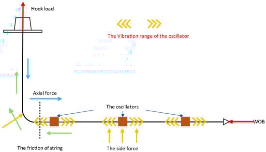
Figure 1.
The installation of multiple oscillators in lateral section.
Meanwhile, since the vibrational load generated by the oscillator acts on the drill string within a certain range and this oscillatory load is cyclic and alternating, it exerts a certain influence on the fatigue damage of the drill string. Currently, relatively few studies in the literature address the influence of hydraulic oscillators on drill string fatigue. In practice, however, the effect of hydraulic oscillator on drill string fatigue damage is twofold: On one hand, by eliminating the more detrimental stick-slip vibrations and reducing buckling, it decreases macro-level, catastrophic fatigue risk; On the other hand, the oscillator itself acts as a “fatigue source”: it actively introduces high-frequency vibrations, continuously accumulating microscopic damage at stress concentration points on the drill string. Consequently, it is essential to analyze how oscillators affect drill string fatigue damage to avoid potential negative impacts.
However, existing studies have predominantly focused on optimizing the placement of a single oscillator and evaluating its drag reduction performance. In contrast, there remains limited research on the vibration propagation distance between multiple oscillators, multi oscillator superposition vs. interference, and unified treatment of intact vs. cracked pipe under multi point excitation. To analyze the inherent laws of non-interference between multiple oscillators, vibration range overlap, and fatigue effects on both intact and initially defective drill strings, this paper establishes a research framework to fill the gap in stress wave propagation and fatigue damage characteristics of drill strings under multi-point oscillation. First, based on tribology and wave theory, this study selected the Stribeck friction model, taking into account the characteristics of low drill string movement speed and continuous transition of friction properties between dynamic and static states during sliding drilling in horizontal sections, as well as the computability of the model. Combined with the wave equation, the oscillation range of the drill string was determined, a dynamic model of the drill string in the horizontal section was established, and the transient dynamic response of the drill string with multiple oscillators was solved, and the parameters influencing vibrational waves were analyzed. Subsequently, building on the research on the mechanism of action of multiple oscillators and integrating the theory of drill string fatigue damage, the study further explored the impact of oscillation on drill string fatigue damage. This work provides new insights for the research on the mechanism of multi-point vibration and fatigue damage of drill strings.
2. Review on Oscillation Mechanisms and Drill String Fatigue Damage
2.1. Vibration-Induced Drag Reduction Mechanism of Drill String
In 1966, Pohlman [6] investigated systems in a large-scale motion state and found that, when vibrations are applied perpendicular to the contact surfaces, the normal contact force and the coefficient of friction at the interface can be correspondingly reduced, thus achieving the goal of reducing the friction force between the surfaces. In 2009, Newman [7] developed a drillstring mechanical model incorporating downhole dynamic excitation, and the numerical results showed a deviation of about 14% compared to the experimental data. Wicks [8,9] proposed that axial vibration tools can effectively increase the maximum displacement limit for extended-reach wells, and used transient dynamics to simulate the propagation of axial forces along the drillstring equipped with an axial vibration tool. He used a one-dimensional dynamic model to calculate the frictional resistance in the moving sections, while employing a three-dimensional static model to calculate the contact forces and friction in the stationary sections, thus developing a drillstring vibration dynamics model. Liu [10] proposed that the classical Coulomb friction theory does not apply to the drag-reduction mechanism of axial oscillation tools. Zhang [11] conducted theoretical and experimental research on the installation position of hydraulic oscillators. The results indicate that after installing the hydraulic oscillator according to the proposed calculation method, The results indicate that after the hydraulic oscillator is installed based on the proposed calculation method, the drilling efficiency has been enhanced. Shi [12] established a drill string dynamic model incorporating a hydraulic oscillator, which was solved using the finite difference method. Taking drag reduction efficiency as the objective function and considering constraints such as drill string failure and hydraulic losses, parametric optimization of drag reduction factors was carried out. Yu [13] developed a tool that uses a pulse generator to drive multiple vibration subs, which can realize drill string creep while reducing hydraulic pressure loss. Field test results indicate that this tool can improve the weight on bit (WOB) transfer efficiency. Although the tool takes into account the impact of multiple oscillations on the drill string, the analysis was mainly conducted from the perspective of field tests, with a lack of relevant theoretical research.
Regarding the drag-reduction mechanism analysis of a single oscillator, extensive research has been conducted by researchers. The study of the vibration-induced drag reduction mechanism can generally be divided into three categories: (1) the excitation force of the oscillator drives axial motion of the drillstring, transforming the friction in the moving sections from static to dynamic friction, thereby reducing frictional resistance; (2) the periodic vibrations of the oscillator induce reciprocating motion of the drillstring, and when the vibration speed caused by the excitation force exceeds the feeding speed, the average friction force within one cycle is reduced, thus lowering the frictional resistance; (3) during axial vibration, radial vibration occurs, causing the contact between the drillstring and the wellbore to shift from continuous contact to intermittent contact, thereby reducing frictional resistance.
In summary, current mainstream research on vibration-based drag reduction mechanisms primarily focuses on the influence of a single oscillator, while studies concerning the superimposed and interactive effects of multiple oscillators remain notably scarce.
2.2. Drill String Fatigue Damage Mechanism
Many scholars have researched the fatigue life of drill strings. In 1945, Miner proposed the famous linear cumulative damage theory [14]. Manson [15] divided the fatigue process into two stages: crack initiation and crack propagation, and established a bilinear fatigue cumulative damage theory using the linear cumulative damage rule in different stages. Paris [16] provided an expression for the crack propagation law, known as the Paris law, through fracture mechanics, and estimated the fatigue life based on crack propagation, providing a new method for studying fatigue life. Forman [17] considered the effect of material fracture toughness on crack propagation rate, improved the Paris law, and developed the Forman model. Walker [18] further considered the impact of stress ratio on fatigue crack propagation rate and proposed the Walker model. Howard et al. [19] introduced research methods for drillstring cumulative fatigue damage and crack propagation, and scientifically discussed how to determine the periods for fatigue testing and drillstring replacement. Wu [20] proposed a model to calculate the bending stress and life of the hazardous areas of the drillstring. Based on the Lubinski theory, a bending model for the drillstring was established, and the bending stress in the hazardous areas of the drillstring was obtained. Then, the fatigue life of the drillstring was predicted by combining the S-N curve. Gao et al. [21] focused on the uncertainty factors in drill string service life, including uncertainties in the working environment and workload. Lin et al. [22] proposed a computational model that predicts the fatigue life of both intact and cracked drill pipes by considering alternating bending stresses and treating other loads as constant values. Chi et al. [23] utilized computer programs to solve the longitudinal and torsional vibration models of the drill string and obtained the maximum and minimum axial and tangential stresses acting on the drill string. Based on the compound crack propagation theory and fracture mechanics methodology, they established a computational model for predicting the fatigue life of the drill string under combined torsional and longitudinal vibrations. Ojanomare et al. [24] determined the stress intensity factor in the drill string through a multi-parameter weight function. Then they substituted it into the Paris fatigue crack propagation formula to estimate the fatigue life of the drill string. Su et al. [25] presents a field-oriented comparative analysis of drill string fatigue evaluation methods, incorporating corrosion effects through systematic calculation of axial forces, cyclic stresses, and fatigue limits. Zhu et al. [26] characterized the dynamic behavior of drill strings in medium-shallow horizontal wells. The investigation examines the influence of multiple parameters—including the quantity and sizes of heavyweight drill pipes, as well as the impulse force and placement of hydraulic oscillators—on the drill string’s dynamic characteristics and fatigue life. Nevertheless, the study’s exploration of fatigue damage mechanisms remains relatively limited.
The current body of literature demonstrates comprehensive modeling capabilities for drill string fatigue in complex stress environments, yet reveals a conspicuous absence of studies addressing vibration-induced fatigue from oscillators, particularly the synergistic effects of multiple oscillator configurations.
3. Drill String Vibration and Fatigue Damage Theoretical Model
3.1. Drill String Dynamic Model Considering the Effect of Oscillators
In this study, the drill string is decomposed into two modeling components: (1) a one-dimensional dynamic rigid-body model for vibration analysis of the horizontal section of the drill string, and (2) the torque-and-drag response along the entire drill string is evaluated using a three-dimensional soft-string model.
The overall loading configuration of the drill string is illustrated in Figure 2, while Figure 3 presents the differential force analysis of an infinitesimal drill string element ds.
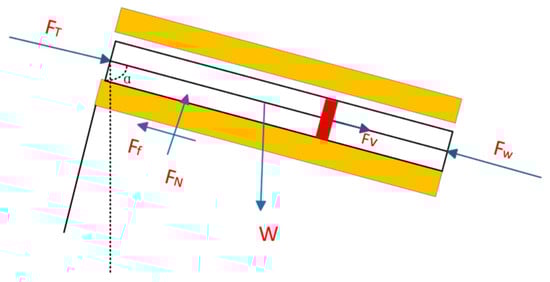
Figure 2.
Axial Vibration Force Model of the Drill string.
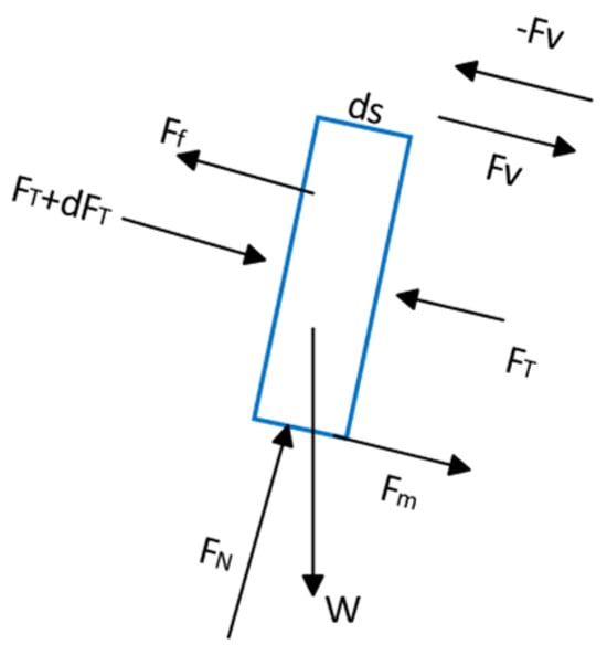
Figure 3.
Differential Element ds of the Drill string and Its Force Components.
The fundamental assumptions are as follows:
- (1)
- The loading and deformation of the drill string remain within the elastic range;
- (2)
- The deformation of the borehole wall rock is neglected;
- (3)
- The drill string is assumed to stay in continuous contact with the borehole wall, and therefore its curvature is identical to the wellbore curvature;
- (4)
- Only the axial vibration of the drill string is considered;
- (5)
- The excitation force is transmitted axially toward both ends of the drill string;
- (6)
- During the instantaneous analysis, the rate of penetration (ROP) is taken as zero, and the displacement boundary condition at the bit remains unchanged.
Additionally, it should be noted that this study focuses on the mechanical characteristics of the drill string in the horizontal section under axial oscillator excitation. Since the trajectory of the horizontal section is generally smooth, with minimal curvature variation, and the oscillator primarily generates axial oscillation, the aforementioned assumptions are considered appropriate. However, the model is not fully applicable in cases where the drill string experiences severe stick-slip vibration, significant whirl motion, or when the wellbore trajectory exhibits high tortuosity. Such cases are not covered within the scope of this paper.
On this basis, the following equilibrium equation can be derived:
Because the drill string is an elastic body of finite length subjected to dynamic excitation, treating it as a lumped single–degree-of-freedom system can lead to significant errors due to the distributed nature of the loads. Conversely, modeling it as a continuous beam with infinitely many degrees of freedom results in highly complex calculations with poor numerical convergence. Therefore, in this work, the horizontal section of the drill string is discretized using the finite element method, and the resulting system of equations is solved through numerical time integration.
3.2. Finite Element Model of the Drill String Considering the Influence of the Oscillator
According to the loading characteristics, the drill string is discretized into finite elements, and the structural components are represented using nodal solid (or continuum) elements. Based on this discretization, the governing equation of motion for the drill string can be expressed as:
The mass matrix M can be expressed as:
And the stiffness matrix K is given by:
The damping matrix C is obtained by superimposing the structural damping matrix Cs, the drilling fluid damping matrix Cm, and the dry-friction damping matrix Cf, Each component is converted into its equivalent viscous form and multiplied by an n-order identity matrix, yielding the combined damping representation denoted as:
The load vector Q is assembled from the resultant axial forces acting on the nodes of each finite element, and can be expressed as:
3.3. Friction Model Between the Drill String and the Wellbore
During axial vibration, the frictional interaction between the drill string and the wellbore exhibits highly complex nonlinear behavior. Owing to the strong nonlinearity of the friction force, directly incorporating the friction term as a dynamic load into the vibration equation often leads to chaotic responses or non-smooth bifurcation phenomena, making an exact analytical solution unattainable. In this study, the dry friction between the drill string and the borehole wall is simplified using the equivalent viscous damping approach.
When the excitation force is sinusoidal, the equivalent viscous damping coefficient corresponding to dry friction can be expressed as [8,9]:
Assuming an arbitrary point on the drill string is located at a distance x from the oscillator, the axial displacement at this point can be written as:
By differentiating the above expression with respect to time, the axial vibration velocity can be written as:
Substituting this relation into the Stribeck friction model, the friction coefficient is obtained as
Integrating the above expression over one excitation period yields the mean friction coefficient:
In the one-dimensional case, the wave equation governing the drill string motion within the influence zone of the oscillator can be written as
The solution of Equation (12) can then be expressed in the form
Consequently, the oscillator influence range L and the axial amplitudes U(x) within this range can be determined. Using the parameters obtained from the wave model, the dry friction within the oscillator’s influence zone can then be converted into an equivalent viscous damping in Equation (7).
3.4. Solution of the Vibration Equation Under the Combined Action of Two Oscillators
When a cross-excitation region is generated between two oscillators, the axial displacement of the drill string changes from the form in Equation (8) to those in Equations (14)–(16):
Because the resulting governing equation constitutes a multi-degree-of-freedom forced vibration system with damping, the Newmark-β method is employed for numerical solution.
The procedure is as follows:
- (1)
- Initialization
① Assemble the mass matrix M, stiffness matrix K, and damping matrix C.
② Prescribe the initial displacement and initial velocity . The initial acceleration is then obtained from the equation of motion at t = 0:
③ Specify the Newmark integration parameters β and γ as well as the time step Δt, and compute the corresponding integration constants:
④ Compute the effective stiffness matrix .
- (2)
- For each time step
① Evaluate the effective load vector at time t + Δt
② Solve for the displacement
③ Compute the acceleration and velocity at time t + Δt
To reduce numerical errors, the dynamic response of the horizontal section of the drill string under dynamic and static loads is computed separately according to the principle of superposition in structural dynamics. Unlike conventional dynamic model analyses, in the wave propagation analysis, the model is transformed from a fully dynamic analysis to an equivalent quasi-static analysis by taking the cycle-averaged solution. Specifically, the instantaneous friction coefficient is replaced with its mean equivalent value, which is then substituted into the static frictional torque model [27] to determine the axial stress distribution along the drill string depth.
3.5. Cumulative Fatigue Damage of the Drill String Without Considering Initial Cracks
When the existence of initial cracks is not considered, the fatigue behavior of the drill string material under cyclic loading can be characterized using the S–N curve. The vertical axis typically represents the cyclic stress amplitude(or stress range), whereas the horizontal axis corresponds to the number of cycles to failure, usually plotted on a logarithmic scale, as shown in Figure 4. A series of stress levels and their corresponding fatigue lives obtained from fatigue tests are plotted in this coordinate system to construct the S–N curve. For certain materials, such as most steels, the S–N curve becomes asymptotic after a certain number of cycles, indicating the so-called fatigue endurance. Below this stress limit, the material can theoretically withstand an infinite number of cycles without experiencing fatigue failure.
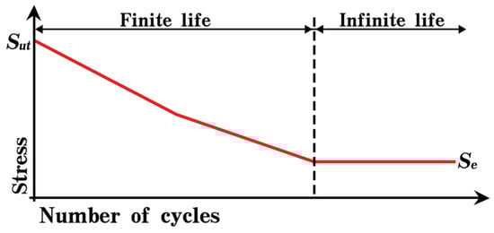
Figure 4.
S-N curve.
Based on the relationship between stress amplitude and fatigue life, the S–N curve can be expressed in analytical form as in Equation (23):
The Miner cumulative damage theory assumes that the fatigue damage of a material or structure under multilevel cyclic loading can be linearly superimposed. In other words, when a material undergoes ni cycles at a given stress level with an associated fatigue life Ni, the damage incurred at that level is treated as a fraction of the total fatigue life, and damages caused at different stress levels are assumed to be independent and additive.
For a single stress amplitude , the corresponding fatigue life can be obtained from the S–N curve. If the material experiences cycles at this stress amplitude, the resulting partial fatigue damage according to Miner’s rule is:
When the material or structure is subjected to multiple stress amplitudes , with corresponding fatigue endurance , and the actual numbers of cycles at each level being , the accumulated damage at each level is
According to Miner’s linear cumulative damage hypothesis, the total fatigue damage is:
If the fatigue failure criterion is defined as , then the condition for fatigue failure of the drill string material is
Miner’s rule assumes linear cumulative damage. For drilling dynamics, nonlinear accumulation may be expected. Since the hydraulic oscillators in this study produce constant-amplitude excitation forces, the Miner model is adopted to evaluate the cumulative fatigue damage of the drill string under the oscillator-induced loading. Complex nonlinear vibrations induced by rock-bit reaction and drill string contact with the wellbore are not considered herein.
3.6. Crack Propagation Model of Drill Strings with Initial Micro-Cracks
Drill string often contain initial cracks due to manufacturing defects, corrosion, wear, and tool bites. To evaluate crack propagation damage, it is first necessary to determine the crack geometry factor and the stress intensity factor, measure the initial crack size using non-destructive testing, and then calculate the critical crack length under given stress conditions. The crack growth damage can then be evaluated according to an appropriate fracture mechanics model.
In this study, the Paris law is employed to quantify the fatigue crack-growth damage [16]. The crack-growth rate is expressed as:
The stress intensity factor is:
Since cracks in drill rods are often surface semi-elliptical cracks, the crack geometry factor can be calculated as:
The number of cycles for a crack to propagate from the initial crack to the critical crack is:
Integrating the above expression yields:
3.7. Computational Procedure for Drill String Fatigue Damage
Fatigue damage of the drill string originates from the accumulation and propagation of cracks under cyclic stress conditions, in which both the tool loading and the wellbore curvature play significant roles. Therefore, it is necessary to establish a crack propagation-based fatigue damage model along the wellbore trajectory to evaluate how the stress and trajectory conditions in each well section affect the drill string fatigue.
The computational procedure of the drill string fatigue-damage model is summarized as follows (see Figure 5):
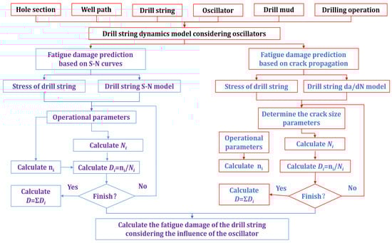
Figure 5.
The computational procedure of the drill string fatigue damage.
① Input baseline data, including wellbore structure, well trajectory, drill string type, hydraulic oscillator parameters, and drilling fluid properties.
② Solve the drill string displacement and stress using the drill string mechanical model
③ Determine the S–N curve parameters of the drill string material based on drilling conditions and experimental data.
④ Identify the parameters of the crack-growth rate parameters according to material properties and operational conditions.
⑤ Compute the actual number of rotations or oscillator cycles experienced by the drillpipe in the well interval.
⑥ Calculate the corresponding fatigue life using either the S–N curve or the crack propagation model.
⑦ Evaluate the fatigue-damage fraction of the drillpipe in the interval.
⑧ Accumulate the fatigue damage over all intervals to obtain the total fatigue damage .
4. Analysis of Vibration Propagation in Drill String and Its Impact on Fatigue Damage
4.1. Model Basic Parameters
Based on the mechanical model established above, an analysis was conducted using a field horizontal well as a case study to investigate the propagation characteristics of oscillations in the drill string and their influence on drill string fatigue damage.
This well has a total depth of 6652 m, with a horizontal section length of 1229 m. The hole diameter of the fourth spud-in is 160 mm, and a PDM tool was adopted for drilling operations. The drill string is configured as follows: Φ160 mm PDC bit × 0.2 m + Φ127 mm PDM × 6.16 m + Φ120 mm non-magnetic drill collar (NMDC) × 9.68 m + Φ101.6 mm heavy weight drill pipe (HWDP) × 82.26 m + Φ101.6 mm drill pipe (DP) × 4752.15 m + Φ127 mm drill pipe (DP).
Two oscillators were used in this operation:
- -
- Oscillator #1: excitation amplitude of 50 kN, excitation frequency of 10 Hz, installed 300 m away from the bit.
- -
- Oscillator #2: excitation amplitude of 50 kN, excitation frequency of 10 Hz, installed 800 m away from the bit.
The basic calculation parameters are listed in Table 1. The basic data in the table is sourced from the drilling data of a shale gas well, and the calculation parameters are set based on general engineering experience. As the model is one-dimensional with no variations in well deviation and azimuth, the drill string has regular dimensions, and the hydraulic oscillator generates regular constant-amplitude oscillations, validation demonstrates that the model is insensitive to the element length and time step.

Table 1.
Parameters of drilling operation and vibration model.
4.2. Case with Only One Oscillator in Operation
4.2.1. Influence of Excitation Amplitude
The aforementioned parameters were substituted into the previously established model for calculation to obtain the dynamic response of the axial vibration of the drill string in the horizontal section. The analysis below examines the scenario where only Oscillator #1 is operational. While keeping other parameters in the case unchanged, the excitation amplitude was set to 10 kN, 50 kN, and 70 kN, respectively, to study the influence of the oscillation amplitude on the effective range of the oscillator. The results are shown in Figure 6. The vibration displacement is the axial displacement in this figure. The yellow straight line represents the axial displacement change in the drill string due to the upper strings weight (vertical and curve section, compressive force), while the axial vibration displacement caused by oscillation is considered as the envelope curves under the influence of the upper strings weight. Due to the compressive effect of the upper strings weight on the horizontal section drill string, the axial displacement gradually changes along the drill string starting from the drill bit.
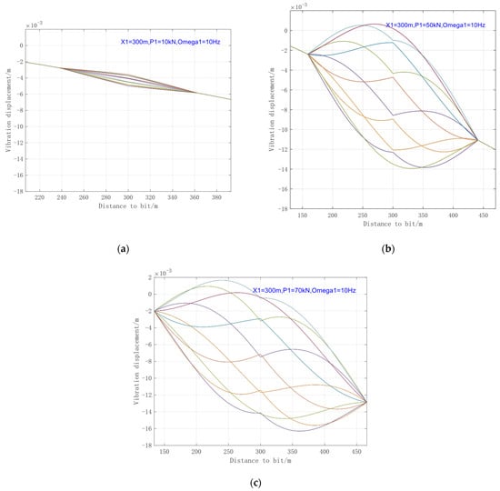
Figure 6.
Envelope Diagram of Drill String Vibration Displacement under Different Excitation Amplitudes. (a) 10 kN; (b) 50 kN; (c) 70 kN.
The envelope curves in Figure 6 are formed by the superposition of vibration displacement curves at multiple time nodes. Each color curve represents the axial displacement of the drill string at a specific time. Due to the periodic nature of the vibration, the number of curves depends on the number of time steps within one cycle (here, the time step is 0.01 s). Since the envelope range is the primary focus of interest, representing the propagation range and intensity of the vibration, the time step annotations for each curve in the envelope diagrams are omitted in subsequent similar figures for clarity.
As can be seen from Figure 6, the effective range of the oscillator increases with greater excitation amplitude. The distortion of the vibration waveform is caused by the phase difference between the excitation force and the vibration displacement.
4.2.2. Influence of Excitation Frequency
When only Oscillator #1 is operational, and while keeping other parameters in the case unchanged, the excitation frequency was set to 5 Hz, 15 Hz, and 20 Hz, respectively, to analyze the influence of oscillation frequency on the oscillator’s performance. The results are shown in Figure 7.
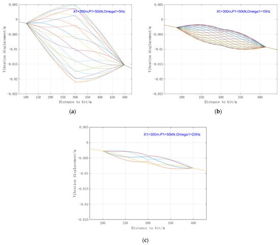
Figure 7.
Envelope Diagram of Drill String Vibration Displacement under Different Excitation Frequencies. (a) 5 Hz; (b) 15 Hz; (c) 20 Hz.
As can be seen from Figure 7: With the increase in excitation frequency, the vibration transmission range decreases conversely; on the contrary, the smaller the excitation frequency, the greater the influence of the generated vibration wave. When the excitation frequency is close to the natural frequency of the drill string, a larger vibration amplitude and a longer transmission distance will be achieved.
4.2.3. Influence of Installation Position
When only Oscillator #1 is operational, its installation position was set at 100 m, 500 m, and 800 m from the bit, respectively. The performance of the oscillator at these different locations is shown in Figure 8.
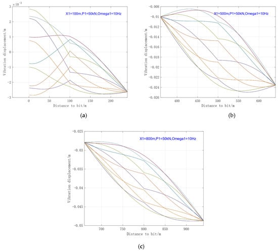
Figure 8.
Envelope Diagram of Drill String Vibration Displacement at Different Installation Positions. (a) 100 m; (b) 500 m; (c) 800 m.
As can be observed from Figure 8, when the excitation force affects the Bottom Hole Assembly (BHA), the propagation distance undergoes some attenuation due to the increased stiffness of the drill string. Furthermore, when the oscillator is positioned too close to the BHA, it may induce positive displacement in the BHA, which could potentially lead to BHA damage.
Based on the above analysis, it is evident that the vibration transmission distance of a single oscillator is limited. Although the friction reduction effect can be improved by increasing the excitation force amplitude, adjusting the excitation frequency, and optimizing the installation position, but the effectiveness of these optimizations has an upper limit. Therefore, increasing the number of oscillators is necessary to enhance the overall friction reduction effect.
The following section analyzes the operational influence when two oscillators are working simultaneously.
4.3. Operation with Both Oscillator #1 and #2 Active
4.3.1. Scenario Without Mutual Interference Between Oscillators
A certain interval is maintained between the two oscillators to ensure no mutual interference. A set of parameters for the oscillators in series is configured for comparative analysis. The specific parameter values are listed in Table 2.
Table 2.
Different Parameter Combinations and Influence Ranges for Two Oscillators Operating.
Based on the previously established model, the vibration scenario when there is no mutual interference between the two oscillators was analyzed, with the results shown in Figure 9.
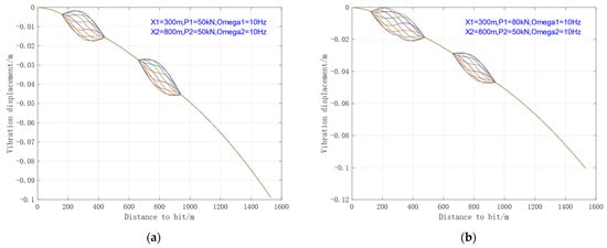
Figure 9.
Influence Law of Two Oscillators Operating Independently. (a) Case1; (b) Case2.
As can be seen from Figure 9, when there is no mutual interference between the two oscillators, their total effective range is restricted by the performance of each individual oscillator. In the absence of mutual interference, the overall effect of multiple oscillators is reflected as the independent operational contribution of each oscillator along the drill string. Therefore, in practical installation and application, it is necessary to optimize and calculate the effective range of each oscillator. On the premise of not affecting the BHA, the effective coverage range of the oscillators should be maximized as much as possible.
4.3.2. Scenario with Overlapping Vibration Ranges Between Oscillators
When the two oscillators are installed at a close spacing, vibrational interference between them will occur. This section analyzes the situation where there is overlapping and interference between the vibration ranges of the two oscillators, divided into two cases: when the two oscillators have the same excitation frequency, and when they have different excitation frequencies.
- (1)
- Same Excitation Frequencies of the Two Oscillators
Considering the scenario where the excitation frequencies are identical (ω1 = ω2 = ω), the vibration displacement u in the overlapping region remains a periodic function. Two sets of parameters for the oscillators in series were configured to conduct a comparative analysis based on excitation force and the extent of the overlapping region. The specific parameters are listed in Table 3, and the vibration displacement envelopes are shown in Figure 10.
Table 3.
Parameters for Overlapping Oscillation Conditions (Same Frequency).
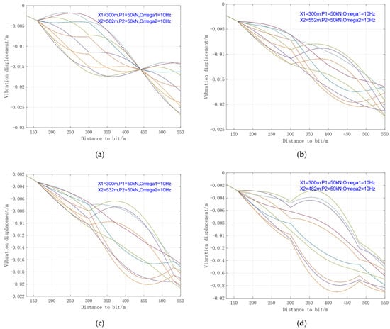
Figure 10.
Envelope Diagram of Drill String Vibration Displacement with Overlapping Oscillations (Same Frequency). (a) Case3—0 m overlapping; (b) Case4—30 m overlapping; (c) Case5—50 m overlapping; (d) Case6—100 m overlapping.
As can be observed from Figure 10, the overlapping of oscillations significantly affects the vibration waveform of the drill string within the influenced range. However, compared to the non-overlapping scenario, the vibration influence range becomes smaller, and the vibration amplitude also tends to decrease. This indicates that, under the same excitation frequency and amplitude, the vibration in the overlapping segment produces a negative effect. Therefore, it should avoid overlapping vibration ranges between oscillators on site.
- (2)
- Different Excitation Frequencies of the Two Oscillators
Based on the principle of energy equivalence, the equivalent viscous damping within the overlapping region can be determined, allowing for analysis according to the theoretical method outlined in Section 1. A set of parameters for the oscillators in series is configured below (specific parameters are listed in Table 4). The resulting vibration displacement envelope under the interactive effect of the two oscillators is shown in Figure 11.
Table 4.
Parameter Combinations with Different Frequencies under Overlapping Ranges.
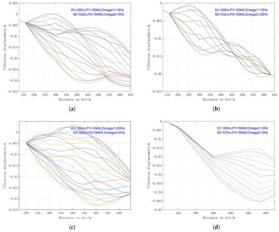
Figure 11.
Envelope Diagram of Drill String Vibration Displacement with Overlapping Oscillations (Different Frequency). (a) Case7—10 Hz–5 Hz; (b) Case8—10 Hz–20 Hz; (c) Case9—20 Hz–5 Hz; (d) Case10—3 Hz–5 Hz.
As can be seen from Figure 11, under the mutual influence of excitations with different frequencies, the envelope curves of vibration displacement still increase significantly and are mostly disorderly, indicating that the vibration tends to be unordered random vibration.
Therefore, when installing multiple oscillators in a drill string, efforts should be made to avoid overlapping of their vibration ranges as much as possible. If there are overlapping areas, the operating frequencies of the oscillators should be kept consistent as far as possible.
4.4. Influence of Oscillator Action on the Fatigue Damage of Drill Strings
4.4.1. Fatigue Damage Analysis in No Initial Crack in the Drill String
When no initial cracks are present in the drill string, the method described in Section 3.5 can be applied to analyze fatigue damage. The steel grade of drill pipe is G, and the drilling fluid has no corrosive effect. The coefficients of S-N (A = 526.6, b = −0.236) are given. The results are shown in Figure 12.
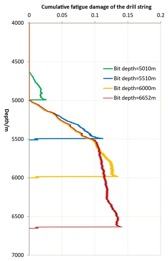
Figure 12.
Drill String Fatigue Damage vs. Bit Depth.
Actually, the fatigue damage (≤1) of the drill string is a spatially distribution over time. To clearly illustrate the fatigue damage along the drill string at different moments (corresponding to different depths), we selected several specific drilling depths (5010 m, 5510 m, 6000 m, and 6652 m) to present the damage distribution along the string at those time instants. As can be observed from the figure, significant damage begins to accumulate in the drill string once the bit depth enters the build-up section. With increasing drilling depth, the damage to the drill string continues to accumulate.
The following analysis examines the impact of oscillator operation on fatigue damage in a drill string without initial cracks. Taking the non-overlapping oscillator scenario as an example, when the oscillator excitation amplitude varies from 10 kN to 120 kN, the model calculates that the additional alternating stress on the drill string (D0 = 101.6 mm) ranges between 4.07 MPa and 48.90 MPa, as shown in Figure 13. Therefore, it can also be observed that as the diameter of the drill pipe increases, the stress generated in the drill string under the same oscillation amplitude decreases.
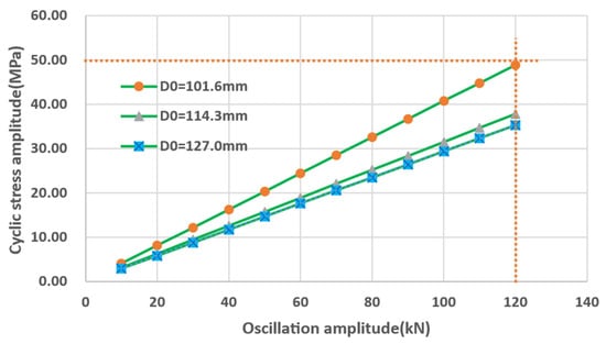
Figure 13.
The alternating stress caused by the amplitude variation in the oscillator.
For the different coefficients corresponding to steel grades and the S-N curves of drill string used (Figure 14). It can be observed that no fatigue damage occurs in the drill string when the cyclic stress remains below the fatigue limit. Therefore, it can be concluded that hydraulic oscillators, within their normal operational amplitude range (<100 kN), generally do not contribute to fatigue damage in drill string without initial cracks. However, if the steel grade of the drill string is downgraded, and the oscillator’s amplitude is too large, it may still lead to fatigue damage to the drill string.
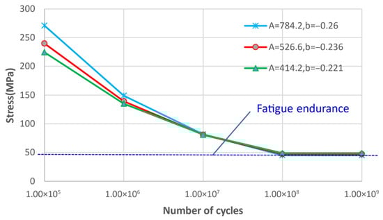
Figure 14.
Comparison of S-N curve coefficients corresponding to different steel grades.
4.4.2. When the Drill String Has an Initial Crack
When there is an initial crack with a depth of 1.27 mm (0.05 in) in the drill string near the hydraulic oscillator, the fatigue damage analysis of the drill string was performed using the method described in Section 3.6 based on the crack propagation model. Here, the values for C, m are taken as 1.6 × 10⁻⁹ and 2.52, respectively. The analysis results, taking the non-overlapping vibration range of the oscillator as an example, are shown in Figure 15.
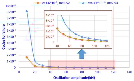
Figure 15.
Relationship between oscillation amplitude and cycles to failure of drill string with initial crack.
It can be observed that as the vibration amplitude of the oscillator varies from 40 kN to 120 kN, the fatigue damage increases progressively, resulting in an exponential decrease in the cycle number to failure. This indicates that when the drill string contains an initial crack, a large vibration amplitude will cause further propagation of micro-cracks in the drill string, reduce the available cycle number, and ultimately lead to the fatigue failure of the drill string. When different steel grades of drill pipe are selected, the corresponding parameters for fatigue damage calculation will vary. It is evident that the steel grade of the drill pipe significantly influences fatigue damage. Additionally, for drill pipes with initial cracks, fatigue damage under different steel grades similarly exhibits a trend of substantial reduction as the vibration amplitude of the oscillator increases.
According to the drilling conditions, when two oscillators are used for drilling 500 m at a ROP of 5 m/h, the service time of each oscillator is calculated to be 100 h. The following analysis focuses on the scenario where the action ranges of the oscillators overlap.
For Case 3 to Case 6, two identical oscillators with a frequency of 10 Hz and an amplitude of 50 kN were adopted. Considering the vibration frequency, the consumed life at the drill string crack can be converted to 3,600,000 cycles. Based on the analysis in Section 4.3.2 and combined with the crack propagation calculation model, the remaining drill string life (usable cycle number) was obtained, as shown by the yellow line in Figure 16 and Table 5. It can be observed that when the action ranges of the two oscillators overlap (at the same frequency), the remaining life of the drill string first increases and then decreases with the overlapping distance, which is mainly related to the vibration amplitude.
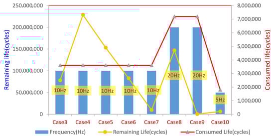
Figure 16.
Fatigue life of the drill string when the operating ranges of the oscillators overlap.
Table 5.
The drill string fatigue life when the operating ranges of the oscillators overlap.
For Case 7 to Case 10, since the operating ranges of the two oscillators overlap and they operate at different frequencies, the results in Figure 15 were calculated using the highest frequency present in each respective case. It can be observed that, due to the different frequencies, the remaining fatigue life of the drill string near the oscillators is predominantly at very low levels when their operating ranges overlap. This implies that when the oscillators’ ranges overlap and they operate at different frequencies, the vibrations severely impact the fatigue damage of the nearby drill string, making it highly susceptible to fracture.
5. Conclusions
- (1)
- The proposed dynamic model provides a novel methodology for investigating the transmission of vibrational stress waves and the characteristics of fatigue damage in horizontal well drilling under multi-source excitation.
- (2)
- Analysis of stress wave transmission in the drill string reveals that a larger excitation amplitude results in a greater range of vibration influence, while an increase in excitation frequency causes the vibration transmission range to exhibit a decaying trend. Even with optimized installation positioning, the effective range of a single oscillator in long horizontal sections remains limited.
- (3)
- When multiple oscillators operate simultaneously without overlapping vibration ranges, the overall effect of multiple oscillators is reflected as the independent operational contribution of each oscillator along the drill string. Through theoretical optimization of the arrangement, maximum coverage of the horizontal section can be achieved.
- (4)
- When multiple oscillators operate with overlapping vibration ranges, under the condition of the same excitation frequency, the vibration in the overlapping segment exerts adverse effects. If the oscillators work at different frequencies, the displacement envelope of the drill string tends to be irregular.
- (5)
- Analysis of the influence of oscillators on the fatigue damage of drill strings without initial cracks shows that, within normal amplitude ranges (<100 kN) of oscillators generally do not contribute to fatigue damage in adjacent drill string sections. However, if the steel grade of the drill string is down-graded, and the oscillator’s amplitude is too large, it may still lead to fatigue damage to the drill string.
- (6)
- When micro-initial cracks exist in the drill string near a hydraulic oscillator, an increase in vibration amplitude leads to an exponential acceleration in crack propagation rate, significantly hastening the process of fatigue failure.
- (7)
- For drilling long horizontal sections, it is essential to optimize the installation positions, oscillation amplitudes, and frequencies of multiple oscillators based on specific field conditions. Simultaneously, timely inspection of the drill string within the oscillators’ influence range must be conducted to mitigate the risk of fatigue failure.
- (8)
- However, since drill string vibration is influenced by multiple factors—such as wellbore trajectory, hole size, BHA, oscillator type, WOB, torque, flow rate, and wellbore frictions—it is challenging to establish a universally applicable quantitative result. The results are for axial vibrations in a particular lateral section and may not directly capture coupled bending/torsion effects. In future research, the model will be applied to a broader range of field wells to statistically derive generally applicable operational guidelines, while scaled laboratory experiments on drill string vibration propagation will also be conducted for further investigation.
Author Contributions
Z.Y.: conceptualization, formal analysis. J.D.: methodology, resources. Y.L.: software, validation. K.X.: methodology, writing—original draft preparation. Z.G.: validation, resources. H.W.: Validation, Investigation. J.W.: software, data curation. M.L.: Validation, Investigation. K.S.: Writing—review and editing, Supervision. All authors have read and agreed to the published version of the manuscript.
Funding
This research was funded by the China National Petroleum Corporation (CNPC) Research Project (Project Number: 2024ZZ46-05), and the Chongqing Research Program of Basic Research and Frontier Technology (Project Number: cstc2019jcyj-msxmX0199).
Data Availability Statement
The data presented in this study are available on request from the corresponding author. The data of the wells belongs to the local data of the company, not suitable for public disclosure.
Conflicts of Interest
Authors Zhiguo Yang, Jianxin Ding, Zhen Guan, Haitao Wang and Jianhua Wang were employed by the company Kunlun Digital Technology Co., Ltd. Author Kai Xu was employed by the company CNOOC China Limited. The remaining authors declare that the research was conducted in the absence of any commercial or financial relationships that could be construed as a potential conflict of interest.
Nomenclature
| Fw | the weight-on-bit reaction force (N) |
| the axial load (N) | |
| the normal contact force exerted by the borehole wall (N) | |
| the pipe friction force (N) | |
| the viscous fluid force generated by the drilling fluid (N) | |
| the oscillator excitation force (N) | |
| W | the weight of drill string (N) |
| the mass of the drill string (kg) | |
| the buoyancy factor (dimensionless) | |
| the maximum excitation-force amplitude (N) | |
| the excitation-force amplitude (N) | |
| the circular excitation frequency (rad/s) | |
| the structural damping coefficient | |
| the stiffness coefficient | |
| the axial displacement of the drill string (m) | |
| M | The mass matrix |
| K | the stiffness matrix |
| C | the damping matrix |
| Q | the load vector |
| Cs | the structural damping matrix |
| Cm | the drilling fluid damping matrix |
| Cf | the dry-friction damping matrix |
| v | the structural nodal displacement vector |
| the inclination of well path (rad) | |
| the dynamic friction coefficient (dimensionless) | |
| the circular frequency (rad/s) | |
| U | the vibration amplitude (m) |
| x | the position of axial vibration (m) |
| the equivalent viscous damping coefficient | |
| φ | the corresponding vibration phase (rad) |
| the ROP (m/h) | |
| μ | the friction coefficient |
| E | the elastic modulus (Pa) |
| the density of drill string (kg/m3) | |
| f(t) | The distributed forces acting on the drill string (N) |
| L | the influence length of the oscillator along the drill string (m) |
| Umax | the maximum axial vibration amplitude (m) |
| C0 | the propagation velocity of the excitation wave in the drill string (m/s) |
| Umax1 | the axial vibration amplitudes at the installation positions of the oscillator one (m) |
| Umax2 | the axial vibration amplitudes at the installation positions of the oscillator two (m) |
| U1 | the vibration amplitudes induced by the t the oscillator one (m) |
| U2 | the vibration amplitudes induced by the t the oscillator two (m) |
| ω1 | the excitation frequencies of the oscillator one (rad) |
| ω2 | the excitation frequencies of the oscillator two (rad) |
| X1 | the distances from the oscillator one to bit (m) |
| X2 | the distances from the oscillator two to bit (m) |
| L1 | the influence ranges of the oscillator one (m) |
| L2 | the influence ranges of the oscillator two (m) |
| β | the Newmark integration parameter one |
| γ | the Newmark integration parameter two |
| Δt | the time step |
| S | the cyclic stress amplitude |
| N | the corresponding number of cycles to failure |
| A | the material-dependent constant one |
| b | the material-dependent constant two |
| a | the crack depth (m) |
| the material constant one obtained from fatigue tests | |
| m | the material constant two obtained from fatigue tests |
| the stress-intensity-factor range ) | |
| the crack geometry factor | |
| the stress range between the maximum and minimum cyclic stresses (MPa) | |
| the crack semi-length (m) | |
| the initial crack (m) | |
| the critical crack (m) | |
| D0 | the average drill string diameter (m) |
References
- Jiang, Z.; Sun, G.; Chen, S.; Li, B.; Dong, H. Key drilling technologies for horizontal wells with ultra-long horizontal sections in Nanchuan shale gas field. Pet. Drill. Tech. 2022, 50, 20–26. [Google Scholar] [CrossRef]
- Fu, J.; Li, G.; Shi, H.; Tian, S.; Wang, D.; Zhang, Y. Research progress of the downhole vibration antifriction technology. China Pet. Mach. 2012, 40, 6–10+45. [Google Scholar]
- Chang, W.; Yi, X.; Wan, J.; Wei, S.; Jiang, S. Application of mechanical vibration drag reduction technology in slide drilling. Mech. Eng. 2015, 3, 146–148. [Google Scholar]
- NOV. Agitator Systems Handbook; NOV Wellbore Technologies: Houston, TX, USA, 2016. [Google Scholar]
- Altamimi, I.M.; Mokrani, S.; Zulkaf, A.H. Axial oscillation tool significantly mitigates the vibration level and enhances drilling performance in conjunction with standard RSS systems. In Proceedings of the Abu Dhabi International Petroleum Exhibition & Conference, Abu Dhabi, United Arab Emirates, 1–10 November 2015. [Google Scholar] [CrossRef]
- Pohlman, R.; Lehfeldt, E. Influence of ultrasonic vibration on metallic friction. Ultrasonics 1966, 4, 178–185. [Google Scholar] [CrossRef]
- Newman, K.R.; Burnett, T.G.; Pursell, J.C.; Gouasmia, O. Modeling the affect of a downhole vibrator. In Proceedings of the SPE/ICoTA Coiled Tubing and Well Intervention Conference and Exhibition, The Woodlands, TX, USA, 31 March–1 April 2009. [Google Scholar] [CrossRef]
- Wicks, N.; Pabon, J.A.; Auzerais, F.M.; Kats, R.; Zheng, A.S. Modeling of axial vibrations to allow intervention in extended reach well. In Proceedings of the SPE Deepwater Drilling and Completions Conference, Galveston, TX, USA, 20–21 June 2012. [Google Scholar] [CrossRef]
- Wicks, N.; Pabon, J.A.; Zheng, A.S. Modeling and field trials of the effective tractoring force of axial. In Proceedings of the SPE Deepwater Drilling and Completions Conference, Galveston, TX, USA, 10–11 September 2014. [Google Scholar] [CrossRef]
- Liu, Y.; Chen, P.; Wang, X.; Ma, T. Modeling friction-reducing performance of an axial oscillation tool using dynamic friction model. J. Nat. Gas Sci. Eng. 2016, 33, 397–404. [Google Scholar] [CrossRef]
- Zhang, S.; Li, N.; Xu, M.; Li, L.; Feng, Q.; Cheng, L. Selection and test of the placement position about hydraulic oscillator. Drill. Prod. Technol. 2020, 43, 20–23+6. [Google Scholar] [CrossRef]
- Shi, X.; Huang, W.; Gao, D. Influences of exeitation force forms of the hydraulie oscillator on drag reduction efficiency. China Pet. Mach. 2023, 51, 11–19. [Google Scholar] [CrossRef]
- Yu, L.; Zhang, Z.; Jiang, Z.; Xu, H.; Zhang, H.; Han, X. Development and field testing of the bionic peristaltic drilling tool. Pet. Drill. Tech. 2025, 53, 55–59. [Google Scholar] [CrossRef]
- Miner, M.A. Cumulative fatigue damage. J. Appl. Mech. 1945, 12, A159–A164. [Google Scholar] [CrossRef]
- Manson, S.S. Interfaces between fatigue creep and fracture. Int. J. Fract. 1966, 2, 327–363. [Google Scholar] [CrossRef]
- Paris, P.C.; Erdogan, F.A. Critical analysis of crack propagation laws. Trans. ASME J. Basic Eng. 1963, 85, 528–534. [Google Scholar] [CrossRef]
- Forman, R.G.; Kearney, V.E.; Engle, R.M. Numerical analysis of crack propagation in cyclic-loaded structures. J. Basic Eng. 1967, 89, 459–464. [Google Scholar] [CrossRef]
- Walker, K. The effect of stress ratio during crack propagation and fatigue for 2024-T3 and 7075-T6 aluminum. Eff. Environ. Complex Load Hist. Fatigue Life 1970, 1–14. [Google Scholar] [CrossRef]
- Howard, J.A.; Halbert, M.E.; Lubinski, A. Systematic Tracking of fatigue and crack growth to optimize drill string reliability. In Proceedings of the SPE/IADC Drilling Conference, Amsterdam, The Netherlands, 22–25 February 1993. [Google Scholar] [CrossRef]
- Wu, J. Drill-pipe bending and fatigue in rotary drilling of Horizontal wells. In Proceedings of the SPE Eastern Regional Meeting, Columbus, OH, USA, 23–25 October 1996. [Google Scholar] [CrossRef]
- Gao, B.; Gao, D. Analysis on Uncertainty of Drill String Lifespan. Pet. Drill. Tech. 2003, 31, 63–66. [Google Scholar]
- Lin, Y.; Luo, H.; Zou, B.; Shi, T.; Weng, X.; Li, R. Research on the failure mechanism and fatigue cycle life prediction of drillpipe. Oil Drill. Prod. Technol. 2004, 26, 19–22. [Google Scholar] [CrossRef]
- Chi, A.; Zhang, J.; Ge, W.; Guo, B. Prediction of Drillstring fatigue life under axial-torsional-combined vibration. In Proceedings of the SPE Unconventional Resources Conference/Gas Technology Symposium, Calgary, AB, Canada, 15–17 May 2006. [Google Scholar] [CrossRef]
- Ojanomare, C.; Cornetti, P.; Romagnoli, R.; Surace, C. Fatigue crack growth analysis of drill pipes during rotary drilling operations by the multiple reference state weight function approach. Eng. Fail. Anal. 2017, 74, 11–34. [Google Scholar] [CrossRef]
- Su, K.; Liu, D.; Jian, X.; Sun, Z.; Wan, L.; Zhuo, Y. Evaluation and influence factors analysis on corrosion fatigue life of the drill string. Drill. Eng. 2024, 51, 15–22. [Google Scholar] [CrossRef]
- Zhu, X.; Zeng, L.; Li, K. Drill string vibration analysis and pressurization scheme for medium shallow horizontal wells. J. Vib. Shock 2020, 39, 190–201. [Google Scholar]
- Johancsik, C.A.; Friesen, D.B.; Dawson, R. Torque and drag in directional well-prediction an measurement. J. Pet. Technol. 1984, 36, 987–992. [Google Scholar] [CrossRef]
Disclaimer/Publisher’s Note: The statements, opinions and data contained in all publications are solely those of the individual author(s) and contributor(s) and not of MDPI and/or the editor(s). MDPI and/or the editor(s) disclaim responsibility for any injury to people or property resulting from any ideas, methods, instructions or products referred to in the content. |
© 2025 by the authors. Licensee MDPI, Basel, Switzerland. This article is an open access article distributed under the terms and conditions of the Creative Commons Attribution (CC BY) license.