Abstract
Understanding the coupled evolution mechanisms of stress, fracture, and seepage fields in overburden strata is critical for preventing water inrush disasters during fully mechanized mining in deep coal seams, particularly under complex hydrogeological conditions. To address this challenge, this study integrates laboratory experiments with FLAC3D numerical simulations to systematically investigate the multi-field coupling behavior in the Luotuoshan coal mine. Three types of coal rock samples—raw coal/rock (bending subsidence zone), fractured coal/rock (fracture zone), and broken rock (caved zone)—were subjected to triaxial permeability tests under varying stress conditions. The experimental results quantitatively revealed distinct permeability evolution patterns: the fractured samples exhibited a 23–48 × higher initial permeability (28.03 mD for coal, 13.54 mD for rock) than the intact samples (0.50 mD for coal, 0.21 mD for rock), while the broken rock showed exponential permeability decay (120.32 mD to 23.72 mD) under compaction. A dynamic permeability updating algorithm was developed using FISH scripting language, embedding stress-dependent permeability models (R2 > 0.99) into FLAC3D to enable real-time coupling of stress–fracture–seepage fields during face advancement simulations. The key findings demonstrate four distinct evolutionary stages of pore water pressure: (1) static equilibrium (0–100 m advance), (2) fracture expansion (120–200 m, 484% permeability surge), (3) seepage channel formation (200–300 m, 81.67 mD peak permeability), and (4) high-risk water inrush (300–400 m, 23.72 mD stabilized permeability). The simulated fracture zone height reached 55 m, directly connecting with the overlying sandstone aquifer (9 m thick, 1 MPa pressure), validating field-observed water inrush thresholds. This methodology provides a quantitative framework for predicting water-conducting fracture zone development and optimizing real-time water hazard prevention strategies in similar deep mining conditions.
1. Introduction
Fossil fuels such as coal and oil and gas remain important energy sources for future human and social development, and their safe and efficient development is of great significance [1]. In the process of coal resource exploitation, the influence of mining response is inevitable [2]. During the mining process of a coal working face, the coal rock, underground aquifers, and surrounding strata within a certain range undergo deformation, fracturing, and displacement. This process generates extensive fractures and leads to surface subsidence [3,4]. These fractures establish interconnected seepage pathways between the aquifer and the working face, thereby increasing the susceptibility of the working face to water inrush hazards [5,6,7]. This process involves a coupling change in the stress, fracture, and seepage fields. With the increase in the mining depth, the variation characteristics of the multi-field response of the coal and rock mass are more different than those of shallow mining. The investigation of multi-field coupling evolution mechanisms in mining-induced fractures within overburden strata holds significant importance for both mine water hazard control and water resource protection.
The failure mechanisms of mining-induced overburden strata are significantly influenced by geological conditions, stress states, and engineering contexts [8]. Typically, the overburden strata above the working face are categorized into three distinct zones extending from the coal seam to the ground surface [9,10,11,12] (caved zone, fractured zone, and bending subsidence zone). Numerous scholars have validated the above finding through various field detection methods [13] and conducted extensive research in this area. Li et al. [14] analyzed the factors influencing the development height of the water-conducting fracture zone (WCFZ) by using a mathematical model, regression analysis, and field measurement. Zhang et al. [15] predicted the height of the WCFZ based on several factors, including coal seam thickness, proportion of hard rock, floor length, mining depth, and dip angle. Wang et al. [16] investigated the three-dimensional distribution characteristics of porosity in overburden strata during longwall mining, providing critical parameters for permeability distribution and valuable insights for the prevention of coal seam water inrush. Based on the composite structural characteristics of the overburden strata, Jiang et al. [17] characterized the dimensions and distribution patterns of fractures within the strata and determined the height of the water-conducting fracture zone. Wang et al. [18] developed a physical model for a mine and analyzed the dynamic evolution processes and underlying mechanisms of karst roof water inrush under different mining sequences. Through an integrated approach combining physical modeling, theoretical analysis, and field detection, Yang et al. [19] investigated the overburden failure mechanisms in shallow, thick coal seams. Their research demonstrated that fractures within the goaf would eventually close, while those at the goaf boundary serve as the primary pathways for water and sand inrushes into the working face. The numerical simulation method can intuitively observe and study the entire dynamic change process of overburden deformation and failure [20,21], which has significant advantages compared with field measurement. Shi and Zhang [22] investigated the mining fracture morphology in overburden strata above the goaf through an integrated approach combining physical modeling, FLAC3D numerical simulations, and field observations. Based on laboratory tests and PFC numerical simulation, Dong et al. [23] studied the trapezoidal evolution law of overburden fractures in extremely thick coal seams and analyzed the failure forms. Song et al. [24] studied the influence of overburden structural characteristics on WCFZ through FLAC3D numerical simulation, theoretical calculation, and field measurement. Through field measurement and numerical simulation, Chang et al. [25] concluded that the final shape of the WCFZ of the working face was a saddle shape and analyzed the key inhibition layer in the cap layer. Yang et al. [26] obtained the transfer law of mining stress by combining similar simulation with numerical simulation considering fractal geometry theory. He et al. [27] studied the influence of mining parameters on overburden failure and conducted secondary development based on FLAC3D. Cao et al. [28] studied the activation mechanism of water-rich faults and the development characteristics of WCFZ in overlying strata through theoretical analysis, FLAC3D numerical simulation, and field measurement. Chen et al. [29] comprehensively compared the results of an empirical formula, engineering measurement, a physical simulation model, and UDEC numerical simulation; they studied the height of a water-conducting fracture zone and analyzed the hazard of water inrush and sand flushing on the working face.
However, critical knowledge gaps persist in current methodologies: Existing permeability models predominantly rely on static laboratory measurements, inadequately addressing the dynamic stress–seepage coupling during progressive face advancement, while prevailing numerical frameworks often oversimplify overburden strata as homogeneous media—neglecting the zonal permeability contrasts between caved, fractured, and bending subsidence zones. Such limitations have led to systematic deviations between predicted and observed water-conducting fracture heights, as evidenced by field measurements in deep mining scenarios.
This paper takes the Luotuoshan coal mine fully mechanized mining face as the engineering background. In this paper, different mining influence zones are simulated by coal and rock samples with different damage degrees. The coupling evolution mechanisms of the mining stress–fracture–seepage field in overburden strata were systematically investigated through integrated laboratory experiments and numerical simulations.
2. Experimental Study on Permeability of Coal Rock Sample in Different Overburden Strata Zoning
2.1. Overburden Strata Zoning
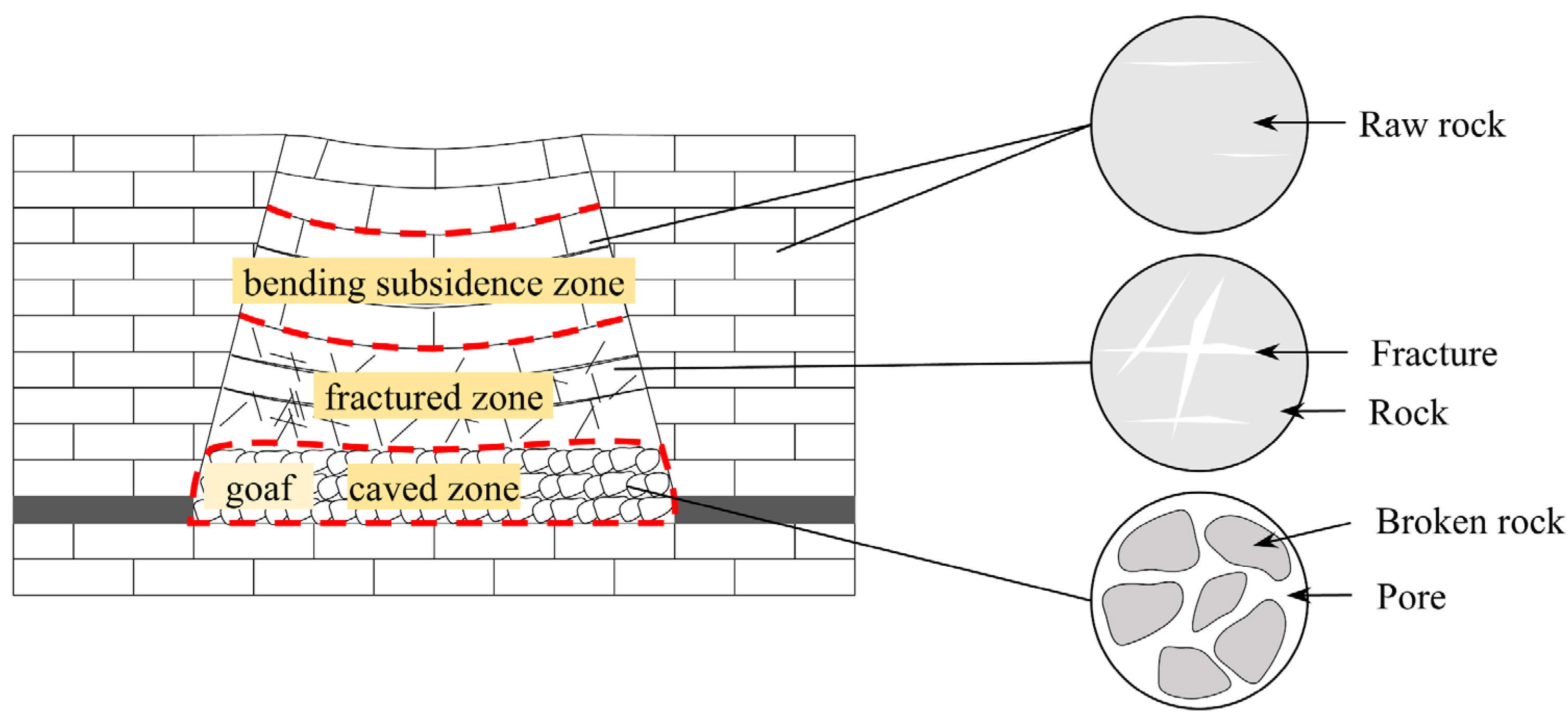
During the coal mining process at the working face, the coal seam will be affected by complex mining, which makes the internal fracture structure of the coal seam become complex. In the overburden strata layer, the damage degree of the coal rock body located in different zones varies greatly, which leads to changes in the permeability of gas and water transport. In the process of coal seam mining, the overburden rock structure usually forms a typical “three zone” structure, comprising the caved zone, fractured zone, and bending subsidence zone (Figure 1).

Figure 1.
Division of overburden strata areas.
The formation of the “three zones” structure (caved zone, fractured zone, and bending subsidence zone) in overburden strata during coal mining stems from stress redistribution and sequential rock failure mechanisms induced by mining activities. Following coal extraction, the disruption of the original in situ stress equilibrium triggers progressive destabilization of the overlying strata from the bottom upward: the immediate roof, deprived of support, undergoes shear fragmentation and free collapse (caved zone), resulting in disordered accumulation and subsequent compaction of broken rock fragments; the strata above, subjected to gravitational loading and stress concentration, develop tensile–shear composite fractures that evolve into interconnected fracture networks (fractured zone), whose growth is governed by lithological combinations and key strata, while the upper distant strata exhibit continuous elastic bending (bending subsidence zone) due to stress attenuation, coordinating deformation through interlayer friction, and composite beam effects, with only minor bedding separation cracks generated. Coal rock seams located in the bending subsidence zone and above are generally considered to be relatively more complete, with no obvious large fracture, and the coal seams are in the elastic stage, which is defined as a raw coal rock sample in this paper. Located in the overburden fractured zone, the rock seams are generally damaged by shearing or pulling, and the degree of fracture development is large; so, this paper defines this type of coal body as a fracture coal rock sample. The caved zone consists of broken residual coal and rock mass, due to the less residual coal in the mining hollow area of the comprehensive mining face; so, this paper defines the coal rock body in the caved zone as a broken rock sample.
2.2. Permeability Model
Matchstick models are commonly used for standard coal rock seepage characteristics, whereby Seidle et al. [30] proposed an effective stress-based theoretical model of permeability for the particular structure of coal:
where kf is the permeability of cleats and fractures in coal seams, mD; cf is the fracture compression coefficient, MPa−1; σ1 is the effective stress, MPa; kf0, σ10 are the permeability and effective stress of the initial state, mD, MPa.
According to many scholars, the fracture compression coefficient cf is not a constant value and varies with the effective stress [31]; it is generally replaced by using the average fracture compression coefficient derived from data fitting:
where cf0 is the compression coefficient of the original fracture, and αf is the change ratio of the fracture compression coefficient with effective stress.
Therefore, combining Equations (1) and (2) can obtain the stress–permeability fitting equation for water, based on which the permeability of the same coal rock sample can be fitted:
where kw is the permeability of water in the fractures of the coal rock body, kw0 is the permeability of the initial state, cw0 is the original fracture compression coefficient, and αw is the ratio of the change in the fracture compression coefficient with the effective stress when the water is seeping.
2.3. Experimental Program
Figure 2 presents the self-developed small-scale conventional triaxial multi-field coupled experimental system for rock bodies. As shown in Figure 2, the system consists of a cabinet panel and liquid filling pump, a peripheral pressure chamber (including axial pressure and confining pressure loading pumps, with an axial pressure loading range of 0–70 MPa), an autoclave (size φ150 × 150 mm, pressure resistance of 30 MPa), a gas–liquid flowmeter (3 sets of different ranges with automatic switching capability), a hydraulic loading system (peripheral pressure loading range of 0–30 MPa), pressure sensors, and a data acquisition system. This system enables precise control and real-time monitoring of loading, strain, flow, pressure, temperature, and gas components in coal rock bodies under high-pressure and constant-temperature conditions.
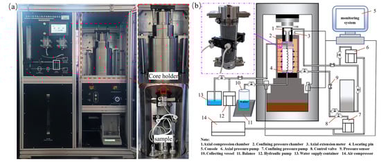
Figure 2.
Small-scale conventional triaxial multi-field coupled experimental system for rock bodies. (a) Experimental system; (b) Schematic diagram.
The experimental samples include raw coal and rock samples, fracture coal and rock samples, and broken rock samples. The specific preparation methods are as follows:
- (1)
- Raw coal rock samples (Figure 3a): The original coal samples and original rock style samples were chosen, and the larger, better integrity, un-weathered coal rock blocks in the coal mining face and overburden strata were directly selected. In the laboratory, according to the ‘coal and rock physical and mechanical properties determination method’, the provisions were processed into standard raw coal samples, at a size of ϕ50 mm × 100 mm.
- (2)
- Fracture coal rock samples (Figure 3b): The standard coal rock samples were processed into sizes of ϕ50 mm × 100 mm and were subjected to a shear test; after the shear damage occurred, the coal samples in which both halves had more complete shear damage were selected for further processing. After the shear damage, the coal sample was generally divided into two halves, and the integrity of each half of the coal rock sample was better, while the penetrating fractures were perpendicular to the two ends of the sample.
- (3)
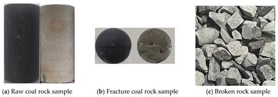
Figure 3.
Coal rock samples with different levels of damage.
Figure 3.
Coal rock samples with different levels of damage.
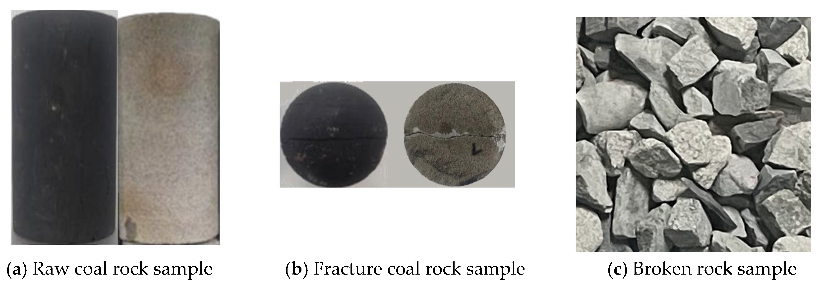
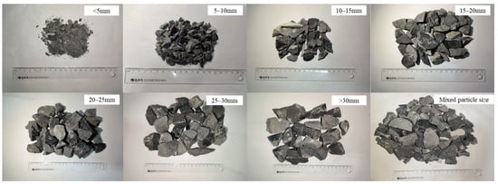
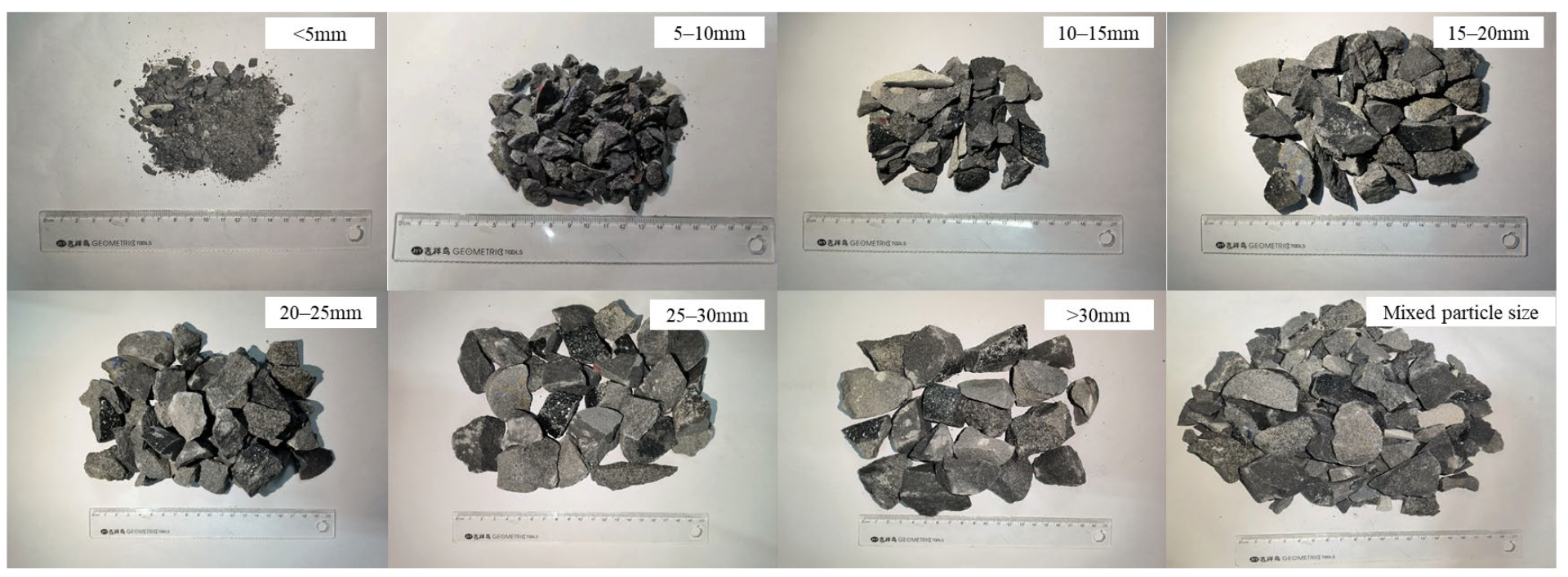
Figure 4.
Broken rock samples with different particle size ranges.
Figure 4.
Broken rock samples with different particle size ranges.
Seepage experiments were performed using different selected samples and recorded after the seepage velocity recorded by the instrument was kept constant; in the experiment, the external fractures of the fractured rock samples were sealed with colloid in order to prevent fluid from seeping from the external surfaces of the samples in the subsequent experiments and affecting the experimental results. It should be noted that the experiment was conducted at a room temperature of 22 degrees Celsius. The experimental steps are as follows: (1) Fix the sensor to the processed sample and fix the specimen to the experimental chamber; slowly increase the axial pressure and adjust the axial pressure to 1 MPa after the specimen is compacted and, at the same time, connect the inlet and outlet pipes with the sensing device. (2) Close the experimental chamber and adjust the peripheral pressure to 1 MPa; keep the axial pressure and peripheral pressure the same, load the water pressure step by step, record the seepage data under each water pressure, and unload the water pressure to 0 MPa when the loading of each level of water pressure is completed. (3) Load the axial pressure and peripheral pressure to the next level at the same time; keep the axial pressure and the peripheral pressure the same; repeat the previous step after the pressure is stabilized, until the axial pressure and the peripheral pressure are loaded to the pre-set value and then stop the group of experiments. (4) Unload the axial circumferential pressure in the equipment and replace the pattern; repeat the above process.
The permeability of the different coal rock samples used in the experiment was determined by the following equation:
where k is the average permeability of each measurement point of the rock sample, m2; η is the fluid viscosity coefficient, taking η = 1 × 10⁻³ Pa·s (water temperature 20 °C); L is the seepage length of the water flow, i.e., the height of the specimen in the test, m; ΔQi is the volume of the water flow that seeped through the specimen during the time of Δti, m3; A is the cross-sectional area of the specimen, m2; ΔP is the difference in the permeation pressure at the upper and lower ends of the specimen, Pa; Δti is the recording point interval time, s.
The fitting parameters for the permeability of different coal rock samples are shown in Table 1.

Table 1.
Fitting results for different samples.
3. Coupled Simulation of Mining Stress–Fracture–Seepage Fields
3.1. Construction of a Coupled Fluid–Solid Simulation Method
In the above, different areas of overburden strata in the process of working face mining were divided into raw coal rock samples, fracture coal rock samples, and broken rock samples. The evolution laws of permeability under different stress conditions were obtained, respectively, through laboratory seepage experiments. Based on the above foundation, the stress–permeability model of coal rock samples with different damage was established. In FLAC3D numerical simulation, the construction of the coupled simulation method of mining stress–fracture–seepage fields relies on the permeability and stress relationship obtained by fitting based on experimental data.
3.1.1. FLAC3D Fluid Structure Coupling Calculation Method
- (1)
- Seepage calculation method
In FLAC3D, fluid passing through porous media is characterized using the fluid mass balance equation, fluid transport Darcy’s law, and constitutive equation for fluid flow. The flow of fluid in FLAC3D is mainly based on Darcy’s law:
In the formula, qi is the directional fluid velocity; kil is the fluid permeability tensor; is the relative permeability coefficient of the fluid; ρf is the fluid density; p is the pore pressure; and gj is the component of gravitational acceleration. It is worth noting that kil is the permeability tensor (m2/(Pa·s)) in FLAC3D, which differs in dimension from the permeability k (m2) obtained in the laboratory. The two can be converted using Equation (6):
In the formula, μ is the viscosity coefficient of the fluid (usually taken as 1.01 × 10⁻³ for water).
When thermal factors are not considered, the constitutive equation for fluid flow is:
The mass equation in the FLAC3D seepage calculation is:
In the equation, qV represents the strength of the fluid source. Substituting Equation (8) into Equation (7) yields the expression for the fluid continuity equation:
- (2)
- Mechanical calculation methods
In FLAC3D mechanics calculations, when a liquid passes through a unit cell, the forces acting on the unit cell mainly include its weight, buoyancy, and flow resistance. The mechanical equilibrium of a unit cell can be expressed by the relationship between the total stress σij and the saturated bulk density ρS:
For a saturated unit cell, its internal materials are solid media and liquid in pores, and its bulk density ρS can be expressed by the following equation:
In the formula, ρd is the density of the dry solid material.
Based on Terzaghi’s theory, the effective stress of saturated porous media in FLAC3D can be expressed by Equation (12):
In the equation, δij is the Kronecker tensor, and σij′ is the effective stress. It should be noted that the compressive stress acting on the unit cell is negative, while the pore pressure is negative in the tension stress.
By combining Equations (10)–(12), the mechanical equilibrium equation of the saturated unit cell can be obtained:
In the formula, ϕ is the negative pressure head. Among them, is the weight of the unit cell, is buoyancy, and is flow resistance.
3.1.2. Module for Updating the Permeability Dynamics of Coal Rock Bodies
Based on the permeability test results of different coal sample types (raw coal rock samples, fracture coal rock samples, and broken rock samples) under different stress conditions, the relationship between permeability and stress in coal seams was quantitatively described using a fitting formula.
Based on Equation (3) and the experimental results, the fitting equations for different types of coal samples are shown in Table 2.
Table 2.
Fitting equations for different styles.
From the fitting equations, it can be seen that the permeability of the raw coal rock samples decreases exponentially with the increase in effective stress, whereas the permeability of the fracture coal rock samples is significantly higher, showing different permeability behaviors. These permeability formulas were embedded into the FLAC3D numerical model by means of FISH language scripts. These formulas will dynamically update the permeability of the coal rock body according to the different stress conditions of the unit, which becomes a module of the dynamic update of the permeability of the coal rock body, and realizes the coupling effect of stress and seepage in the model. The mechanics and seepage module of FLAC3D will combine the changes in the stress field and fracture field to simulate the expansion and deformation of the coal seam fractures during the mining process. Thus, the seepage characteristics of the aquifer during mining can be accurately reflected.
3.1.3. A Coupled Simulation Method of Mining Stress–Fracture–Seepage Fields
The coupled simulation method of mining stress–fracture–seepage fields is based on the evolutionary characteristics of the overburden strata of the working face and the damage permeability behavior of the coal rock body, and the dynamic coupling of the three fields is realized through experimental–numerical joint modeling. The specific methods are constructed as follows:
- (1)
- Coal rock zoning and permeability modeling
Based on the “three zones” structure of mining overburden (caved zone, fractured zone, and bending subsidence zone), the coal rock body is divided into three categories: raw coal samples (uninjured area, permeability attenuation with the stress index); fracture coal samples (damage zone, permeability jumped due to plastic damage); broken coal rock body (caved zone, permeability attenuation with the compaction process). The stress–permeability modeling of the three types of coal rocks used laboratory seepage experiments.
- (2)
- Permeability dynamic updating mechanism
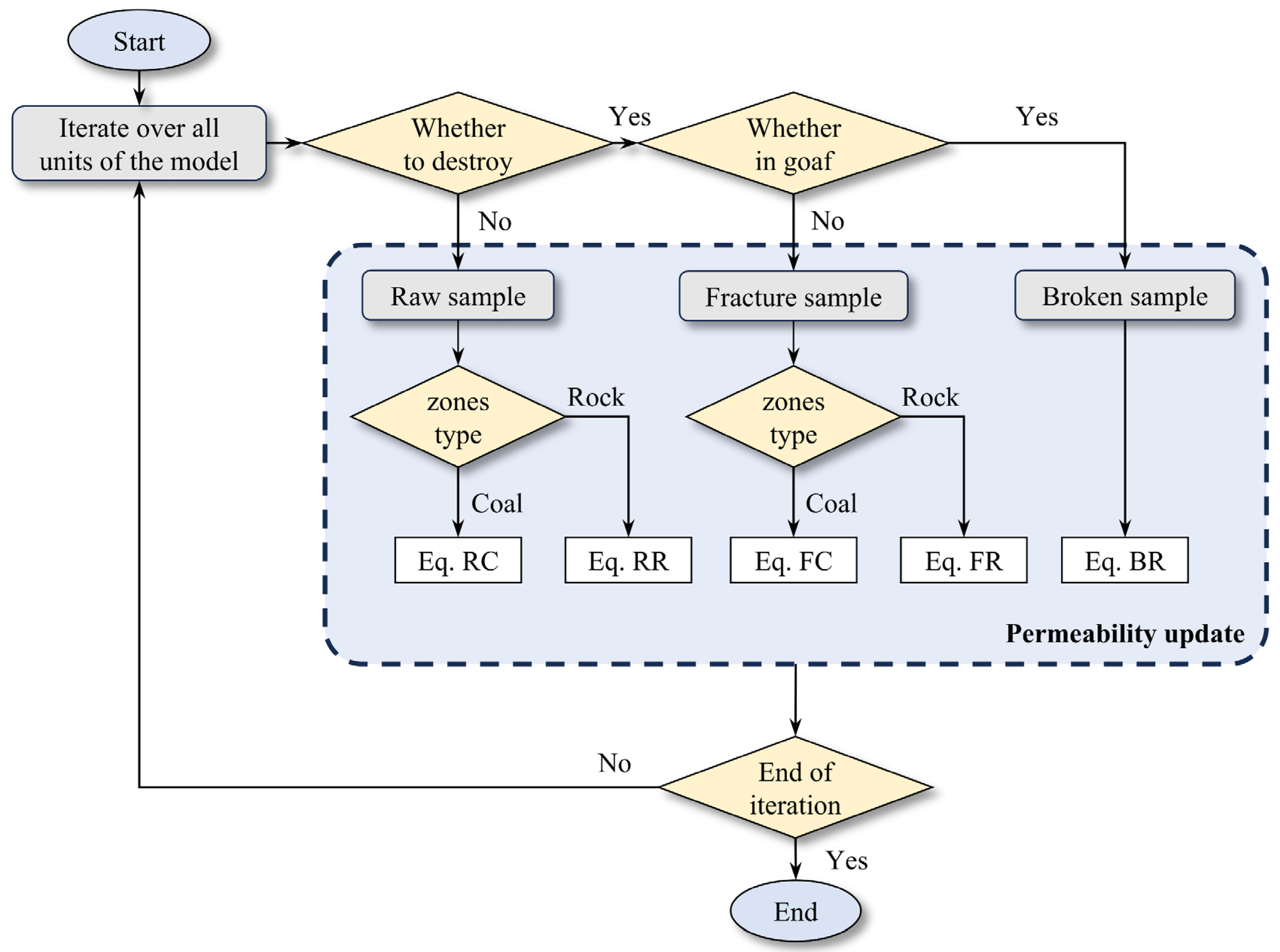
Three types of coal permeability models are embedded in FLAC3D: Raw coal samples are dynamically corrected by the stress–permeability fitting formula; fracture coal samples trigger a rapid increase in permeability based on a yield criterion; broken coal rock bodies combine the caved zone height equation with compaction theory to simulate the nonlinear evolution of permeability with compaction strain. In the process of calculation, the FISH script is continuously called by FISH callback or the whilestepping command, so as to realize the real-time dynamic update of permeability.
- (3)
- Multi-field coupled numerical simulation flow (Figure 5)
 Figure 5. Flow–solid coupling calculation process.
3.2. Engineering Background
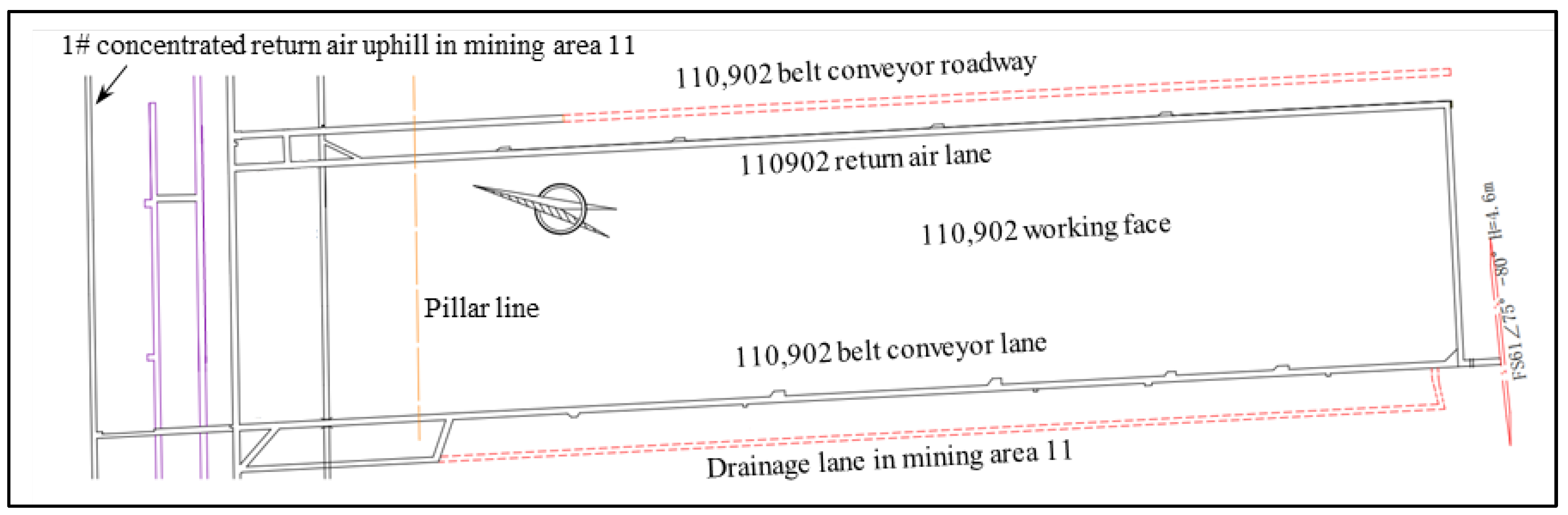
In this paper, we chose to select the 110,901 working face (Figure 6) of Luotuoshan coal mine for the study. According to the report of the deep area fine investigation of Luotuoshan well field and the report of the hydrogeological supplementary investigation of the Austrian grey, the water-bearing layer group in the well field is divided into three categories: the Quaternary loose rock pore phreatic water-bearing rock group, clastic rock pore–fracture confined water-bearing rock group, and Ordovician limestone water-bearing rock group.
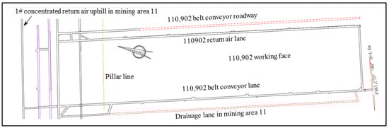
Figure 6.
Diagram of the location of the 110,901 working face in Luotuoshan coal mine.
Analyzing the working face mining stress environment, mining layout, surrounding rock aquifer and mechanical properties of coal rock can help to explore the mutual triggering mechanism of a top and bottom water breakout and roof disaster, the occurrence mechanism, and its main controlling factors. Based on this, this paper investigates the distribution and evolution of mining stress–fracture–seepage fields under the condition of a surrounding rock aquifer and reveals the mutual triggering mechanism of roof-bottom water breakout and roof disaster and its main controlling factors in the working face of 110,901 in Luotuoshan coal mine and similar conditions.
3.3. Numerical Model and Parameters
3.3.1. Model Construction
According to the geological exploration data, the FLAC3D numerical model of Luotuoshan was constructed. The calculation range of the model was taken as strike × dip × height = 500 m × 300 m × 170 m. The average burial depth of the coal seam was taken as 308.10 m. The pressure measurement coefficient was taken as 1. The strike × dip of the working face was taken as 400 m × 200 m, and the boundary protection coal pillar was set up on both sides of the coal seam for 50 m. Considering that No.9-2 coal is one of the main mineable coal seams in the well field, the strike of the coal seam is mainly at NW15~20°, and the dip is a monoclinic stratum tilted to the west, with the dip angle ranging from 5~15°, and the average dip angle is 9°; so, the numerical model was set to have a dip angle of 9°. Accordingly, the geological model was constructed by FLAC3D version 6.0 numerical simulation software (Figure 7). Fixed constraints were imposed on the front, back, left, right, and bottom boundaries of the model; the topsoil stratum above the bedrock was converted into an equivalent load, which was uniformly applied to the upper surface of the model.
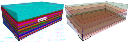
Figure 7.
Numerical model of Luotuoshan coal mine.
3.3.2. Parameter Selection
Based on the geological information of the mine’s comprehensive borehole column map, strata with similar geological characteristics are classified and simplified to ensure that the model can accurately reflect the actual geological conditions of the mine. In addition, response surface methodology (RSM) is often used to optimize parameters and has been widely applied in many fields [32]. Based on RSM, experimental data, and field measurements, all kinds of rock strata in the model are assigned with corresponding physical and mechanical parameters, and their specific values and layering scheme are shown in Table 3, which is used as the basis for the subsequent simulation and analysis of the evolution law of the mining stress–fracture–seepage fields of the overburden strata in the working face.
Table 3.
Physical and mechanical parameters of the reservoir.
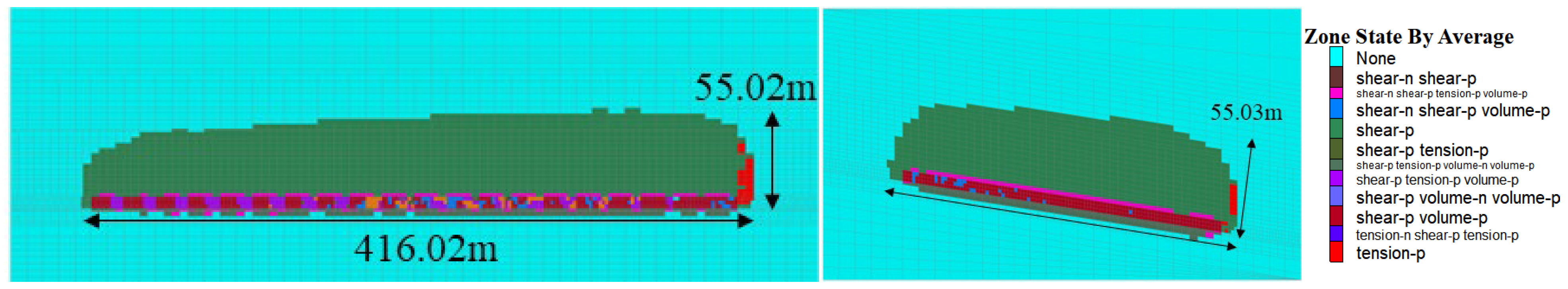
During the advancement process of the 110,901 working face in Luotuoshan coal mine, the actual measured height of the water-conducting fracture zone based on the monitoring and inversion of the leakage of drilling flushing fluid on site was 58 m. Therefore, in order to ensure the reliability of the numerical simulation results in this paper, the height of the water-conducting fracture zone development during the advancement process of the 110,901 working face was simulated, and the results are shown in Figure 8. According to Figure 8, the development height of the water-conducting fracture zone in the numerical simulation is 55 m, which is close to the development height measured on site. Therefore, it is considered that the numerical simulation results in this paper are reliable.
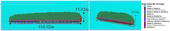
Figure 8.
Numerical simulation results of the development height of water-conducting fracture zones.
3.3.3. Measuring Point Arrangement
The stress redistribution of overburden strata and the dynamic expansion of fracture during the mining process are the key factors inducing disasters such as gas transport and water breakout in coal seams. The measurement points are arranged to monitor the mechanical response and seepage parameters of different layers and zones of the coal rock body in real time. They can quantitatively reveal the dynamic evolution characteristics of the “three zones” structure (caved zone, fractured zone, and bending subsidence zone) and provide data support for the coupling analysis of the seepage field and stress field. Monitoring data can effectively reflect the dynamic updating process of coal rock damage permeability modeling, verify the applicability of the graded permeability formula of ‘raw coal rock samples—fracture coal rock samples—broken rock samples’ in the numerical simulation, and, at the same time, provide a scientific basis for the distribution of over-supporting pressure, the expansion law of the plastic zone, and the determination of the threshold of the sudden change in permeability, which will ultimately serve for the optimization of the mine disaster prevention and control and the mining plan.
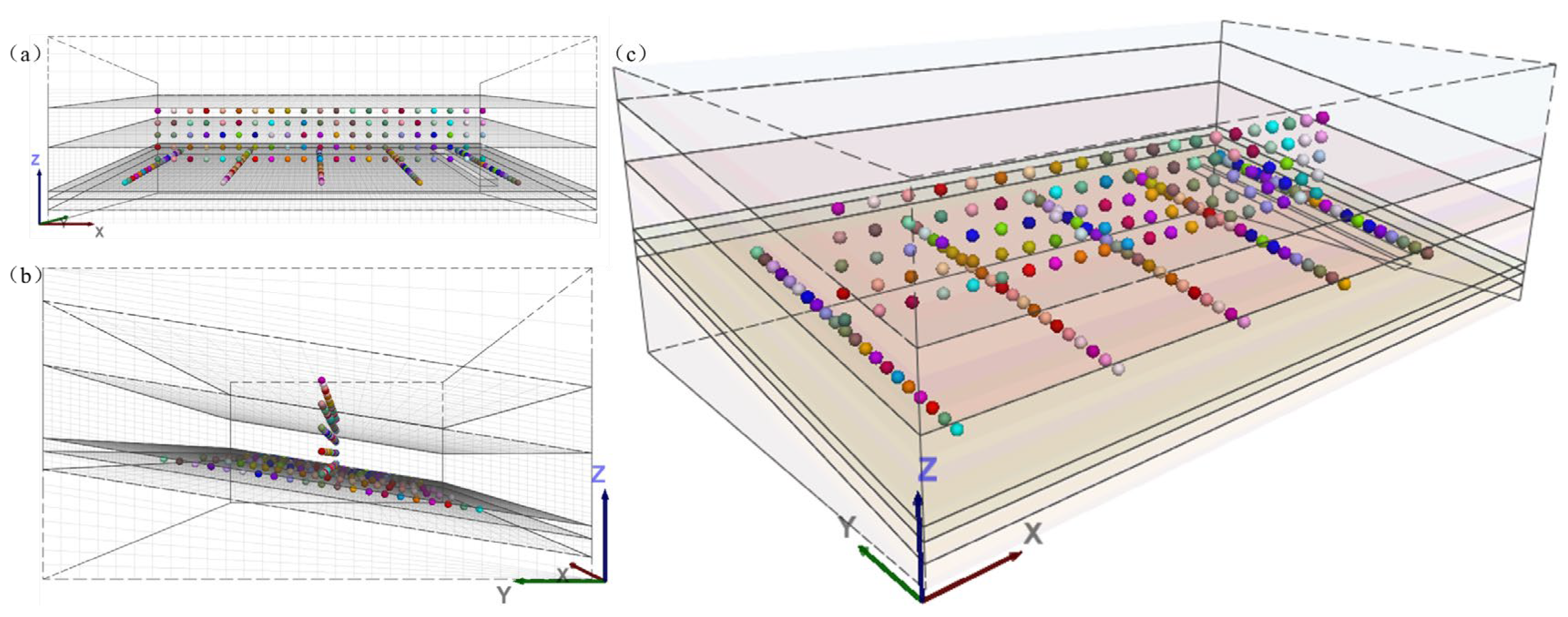
The simulated working face is arranged along the dip, with a length of 200 m, and advances along the strike, with an advance length of 400 m. In order to eliminate the boundary effect, a 50 m boundary-protective coal pillar is reserved around the working face; so, it advances along the x-axis from 50 m to 450 m, and five vertical monitoring lines (x = 50 m, 150 m, 250 m, 350 m, 450 m) are arranged along the strike; each line sets multi-level measurement points (Figure 9) on the coal seam roof (z = 35.5 m) and the overlying rocks above it (z = 50 m, 65 m, 80 m, 95 m). The coal seam roof (z = 35.5 m) and the overlying rocks above it (z = 50 m, 65 m, 80 m, 95 m) are set up with multi-layer measuring points (Figure 9), covering the dip range of the working face from y = 50 to 250 m. The main points are as follows: (1) Measuring points of coal seam roof (z = 35.5 m): they are set up along the dip at 10 m intervals, focusing on capturing the migration patterns of vertical stress concentration zones (the peak of the pressure of the over-abutting support). (2) Overlying fracture zone measurement points (z = 50~95 m): the stress and permeability of the overburden strata are monitored and distinguished from the permeability decay in the raw phase and the jumping behavior after plastic damage. In order to effectively capture the relevant data and evolution pattern of each measurement point, the monitoring interval of the model measurement points is set to 100 steps.
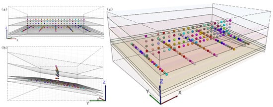
Figure 9.
Measuring point arrangement. (a) Front; (b) Side; (c) Three-dimensional.
In this paper, the concept of damage degree is additionally introduced to monitor in real time the evolution of the damage degree of the overburden strata above the coal seam and the roof plate below the coal seam in the process of working face mining; the seepage mechanics data are integrated in all the measuring points to form a three-dimensional monitoring network of “vertical stratification comparison, stepwise tracking along the strike and dip coverage”, which provides comprehensive parameters for the study of the dynamic evolution of “mining stress field, fracture field and seepage field”.
4. Seepage Evolution Mechanisms of the Mining-Disturbed Overburden Aquifer
4.1. Characteristics of Overburden Permeability Mining Evolution
In order to deeply study the evolution law of the overburden seepage field during the advancement of the coal mine working face, to improve the ability of mine water damage prevention, this paper further analyzes the change characteristics of overburden permeability under the mining stress–fracture evolution. The redistribution of overburden strata stress after mining leads to the development and expansion of fractures, which in turn changes the permeability of the coal and rock body, resulting in significant changes in groundwater transport characteristics. Numerical simulation can be used to construct a dynamic evolution model of the seepage field, combine the stress–fracture–seepage coupling mechanism, and quantify the changes in coal rock permeability during the mining process.
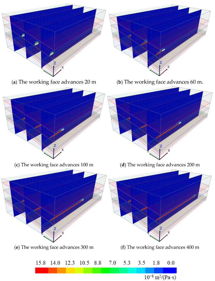
Figure 10 shows the evolution pattern of the seepage field at X = 50 m, 150 m, and 250 m slice locations of the modeled strike during advancement of the working face along the strike.

Figure 10.
Distribution characteristics of seepage field along the strike of the working face.
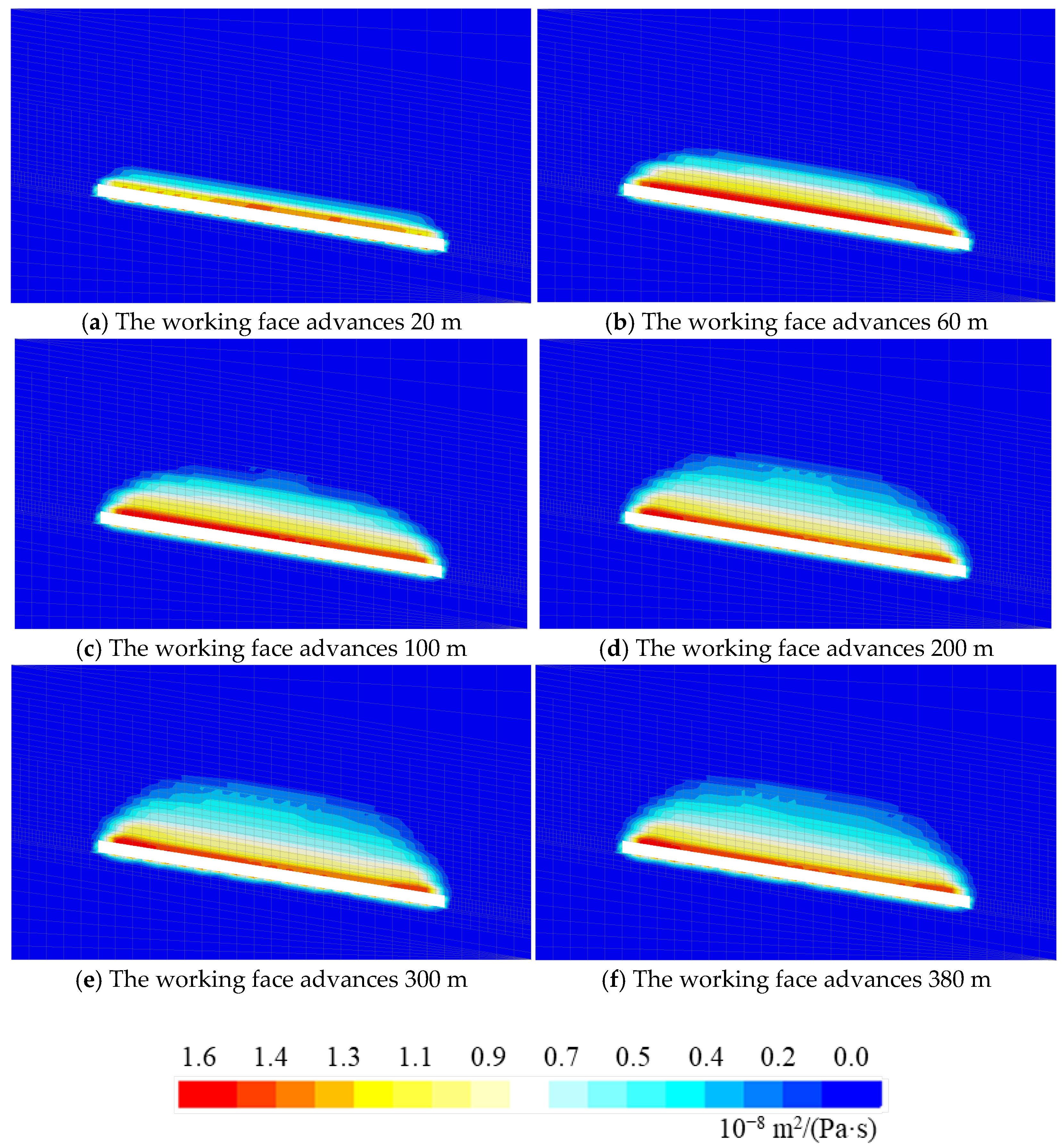
Figure 11 shows the evolution of the seepage field at the position of the X = 150 m slice of the model dip during the advancement of the working face along the strike. When the working face advances to 20 m (Figure 11a), the seepage field is mainly concentrated near the coal seam roof, and the permeability change area is relatively small, indicating that the initial mining influence is limited, and only a local permeability enhancement phenomenon is generated in the front of the working face and the boundary of the mining area. After advancing to 60 m (Figure 11b), the high permeability area expands upward, and the permeability of the fracture zone increases, indicating that the stress adjustment of the overburden strata of the coal seam has caused the initial formation of seepage channels. When advancing to 100 m (Figure 11c), the influence range of the seepage field is obviously enlarged, the rupture degree of the roof is intensified, the fracture network is gradually penetrated, and the permeability is increased as a whole. When advancing to 200 m (Figure 11d), the high permeability zone further develops upwards, the scale of the seepage channel expands, the connectivity of the fractures increases, and the transport capacity of the water and gas improves, indicating that the development of mining fractures has entered a mature stage. With advancement to 300 m (Figure 11e) and 380 m (Figure 11f), the distribution of the seepage field tends to stabilize, and the areas of high values of permeability remain at the boundaries of the fracture zones and goaf, which further verifies the controlling effect of overburden fractures on the permeability performance. Overall, the evolution law of the seepage field indicates that with the advancement of the working face, the formation and expansion of the fractures directly lead to the increase in permeability, and the permeability channel between the goaf and the fracture zone is gradually established and eventually tends to be stable. This study provides a scientific basis for coal mine water inrush risk assessment and seepage disaster prevention and control.
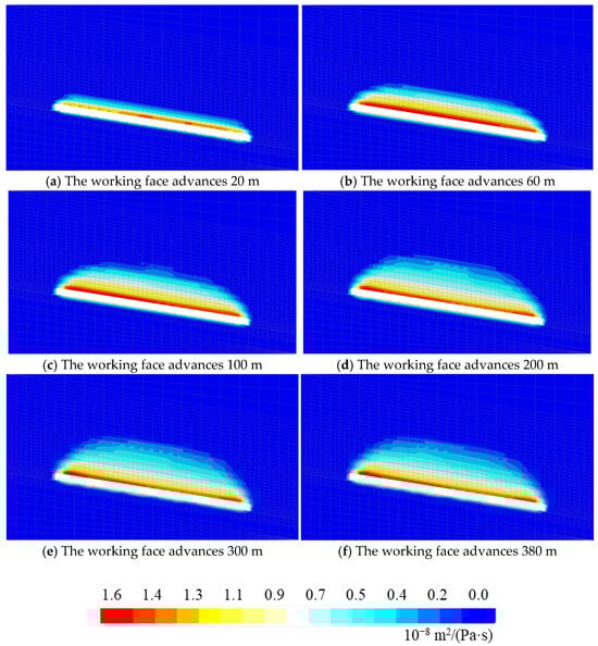
Figure 11.
Distribution characteristics of seepage field along the dip of the working face.
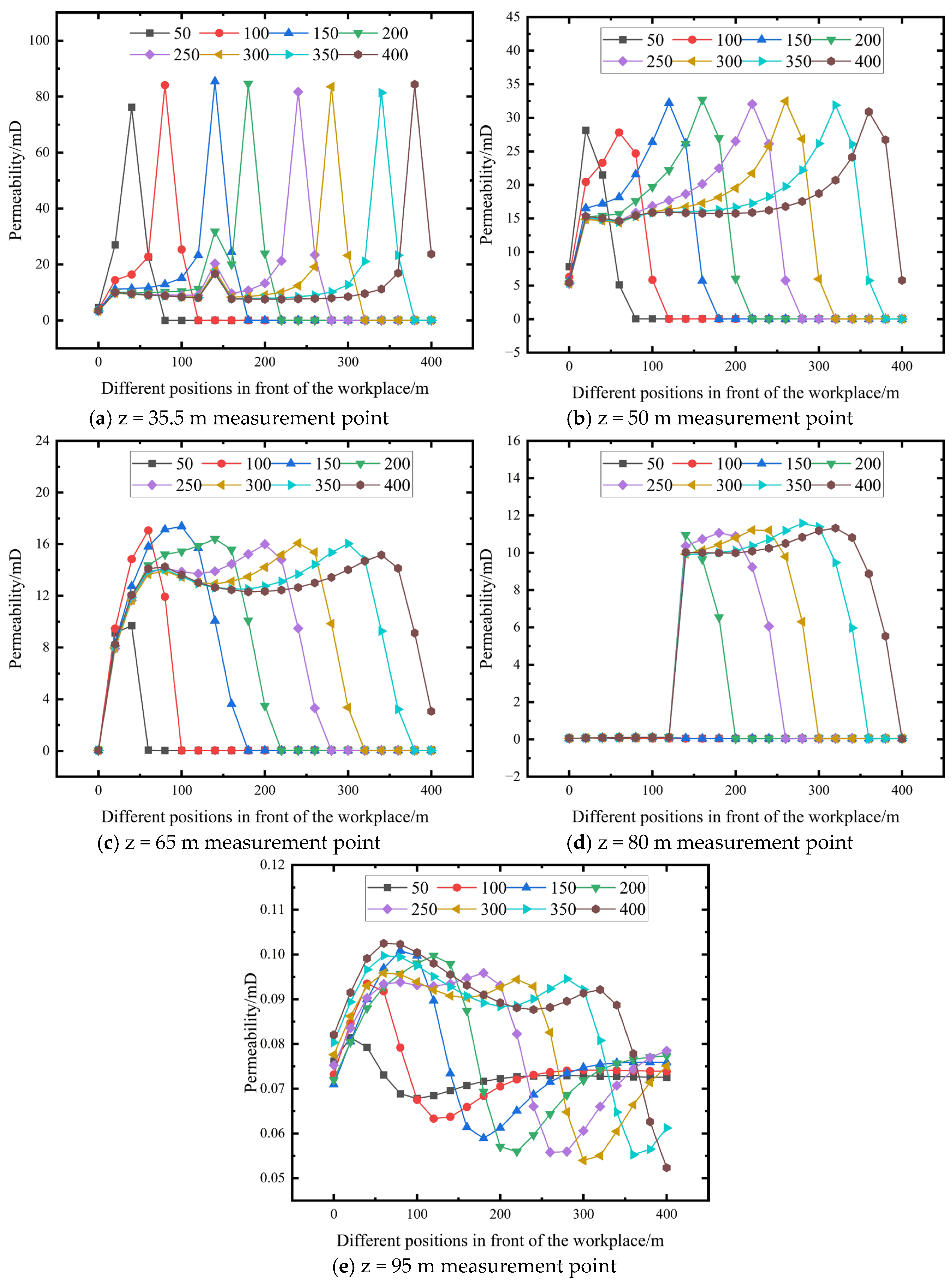
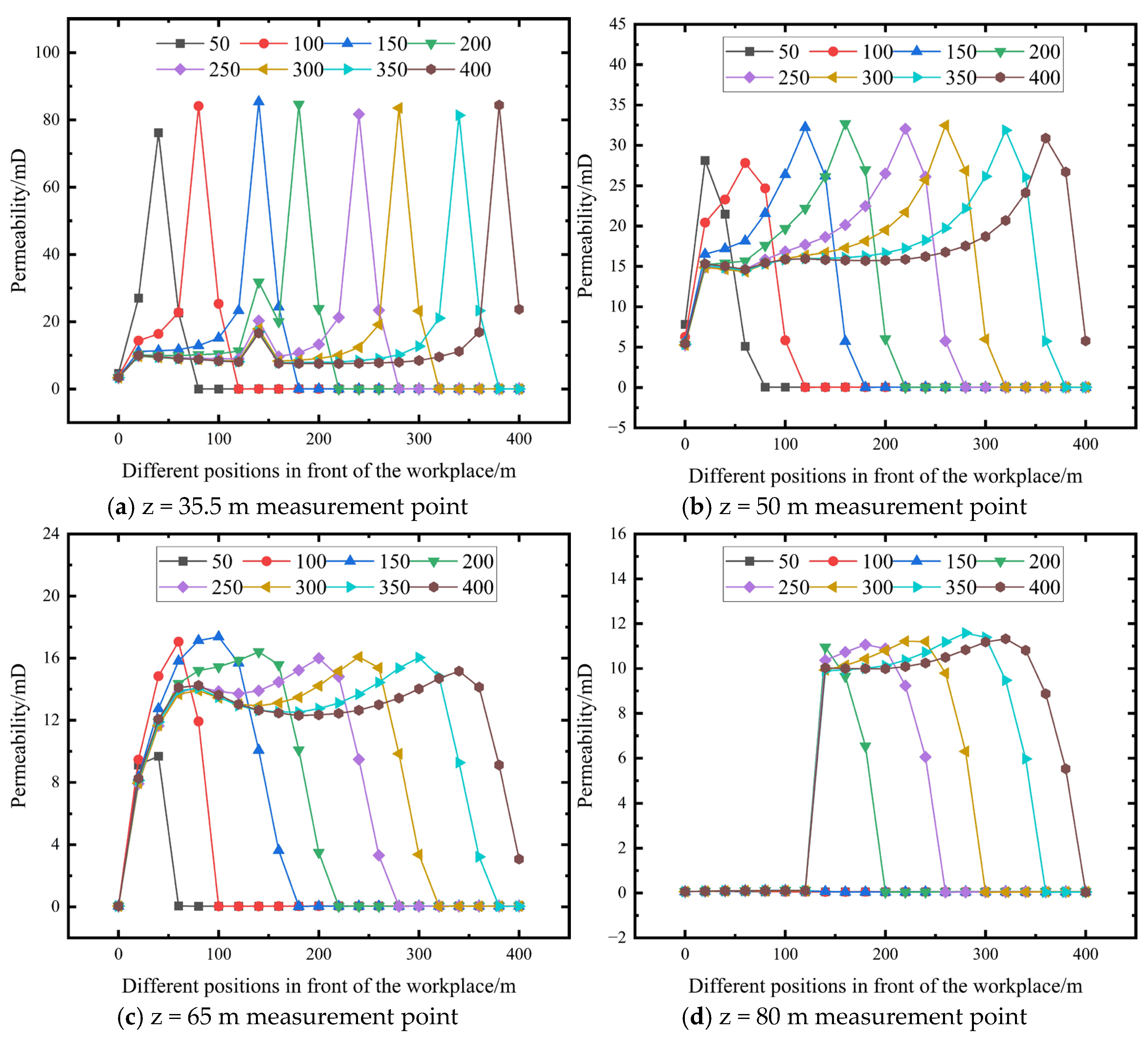
According to permeability monitoring data at the y = 150 m strike line (z = 35.5 m) during face advancement (Figure 12a), the spatial–temporal evolution of mining-induced permeability exhibits significant differentiation, reflecting the multi-physical coupling mechanisms of stress–fracture–seepage fields. When the working face advanced to 50 m, permeability ahead of the measuring line (x = 50 m) surged from 4.62 mD to 26.99 mD (484% increase), indicating plastic damage initiation in the roof strata under abutment pressure. At 200 m advancement, permeability at x = 250 m reached 81.67 mD—an order of magnitude higher than adjacent undisturbed areas—marking fracture network penetration. As advancement progressed to 400 m, permeability at x = 150 m peaked at 15.14 mD (228% increase from the initial point), demonstrating stress concentration migration with face progression. Post-advancement, permeability in the goaf rear (x ≥ 350 m) stabilized at 23.72 mD (4.1 × initial value), confirming persistent seepage channels through plastic zone fractures.
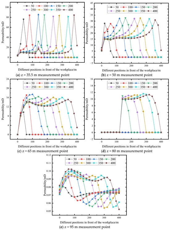
Figure 12.
Evolution of overburden permeability of different working face advance distances.
The permeability has the following evolutionary pattern: (1) Within the range of overshooting influence (50–80 m in front of the working face), the permeability shows an exponential growth, synchronized with the migration of the peak support pressure, which conforms to the three-stage evolution model of “stress compression-fracture emergence-permeability leap”; (2) the lateral coal pillar area (x = 50 m) tends to stabilize after a sharp increase in permeability at the beginning of the advancement (0.0356 mD), reflecting the formation of a low permeability barrier after the protective coal pillar undergoes elastic–plastic deformation; (3) the middle part of the goaf (x = 250 m) shows a sudden change in permeability in the middle and late stages of advancement, which corresponds to the formation of the dominant water-conducting zone of the off-stratum fracture triggered by the breakage of the key layer. This law provides data support for revealing the differences in permeability characteristics among the “three vertical zones” of the overburden strata and indicates that the evolution of the seepage field is regulated by both the opening degree of the mining fracture and the effect of stress recovery.
4.2. Seepage Migration Characteristics of Overburden Aquifer
The hydrogeological conditions of the Luotuoshan coal mine are complex, and the distribution of overburden aquifers has an important impact on mine mining. At a distance of approximately 55 m above the working face (Figure 7), there exists a layer of fine-grained sandstone aquifer, which has a water pressure of about 1 MPa and thus belongs to the medium level of water pressure; the thickness of the aquifer is 9 m, which has strong water storage capacity and permeability, and it is one of the main sources of water influx in the mine. The existence of fine-grained sandstone aquifer makes it necessary to pay special attention to waterproofing measures in the process of working face mining in order to prevent the occurrence of sudden water accidents. Therefore, Luozhoushan coal mine needs to strengthen the monitoring and management of this aquifer in the process of mining to ensure the safe production of the mine.
Figure 13 shows the saturation evolution characteristics at the modeled strike Y = 150 m slice location during the advancement of the working face along the strike.
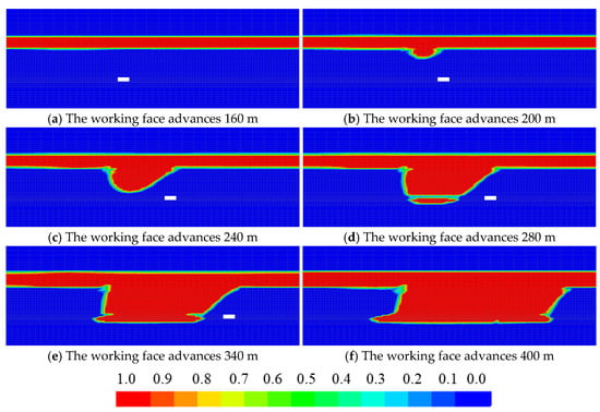
Figure 13.
Distribution characteristics of saturation along the strike of the working face.
Figure 14 shows the evolution characteristics of the pore water pressure field at the location of the Y = 150 m slice of the modeled strike during the advancement of the workface along the strike. The change in pore water pressure shows a clear distribution trend as the working face advances. In the early stages of advancement (before 160 m), the pore water pressure was low and no significant permeability occurred. When advancing to 200 m, the pore water pressure at the measuring point began to rise significantly, especially at the measuring point close to the mining area; the pressure gradually increased, indicating that the water in the aquifer began to infiltrate into the mining area. To more than 250 m, drastic changes appeared in the pore water pressure at a number of measurement points; the pressure peak was obviously related to the concentration of the goaf, indicating that the seepage formed a stable channel and that the working face was affected by water intensification. As it advances to 400 m, the seepage path expands further, and the risk of water damage rises significantly. Therefore, in the actual mining process, we should focus on the evolution of pore water pressure after advancing to 200 m and strengthen the over-drainage and reinforcement measures in order to reduce the risk of water breakout and guarantee the safety of the working face.
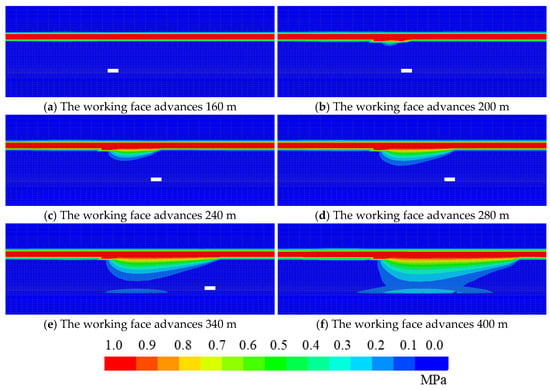
Figure 14.
Distribution characteristics of pore water pressure field along the strike of the working face.
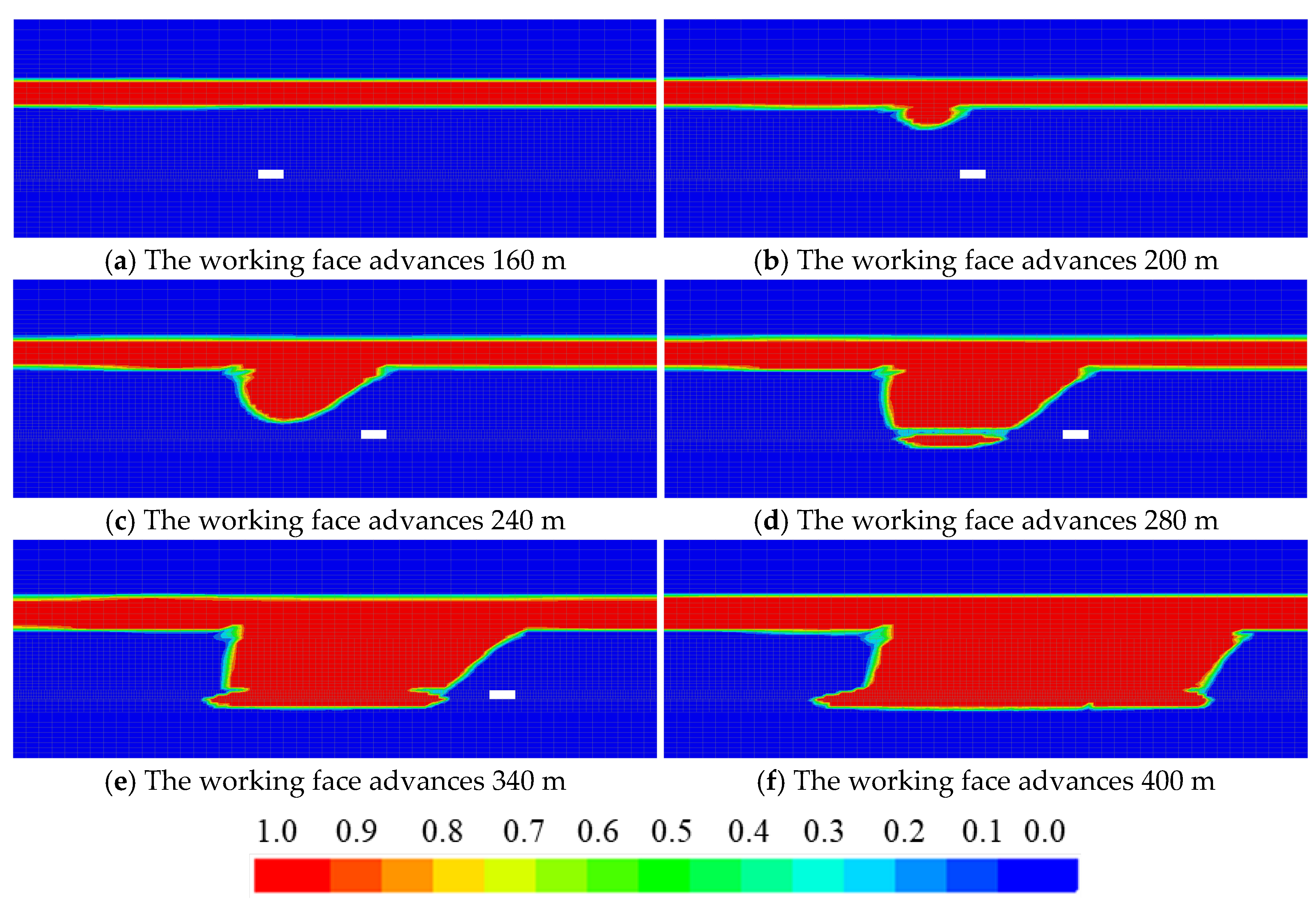
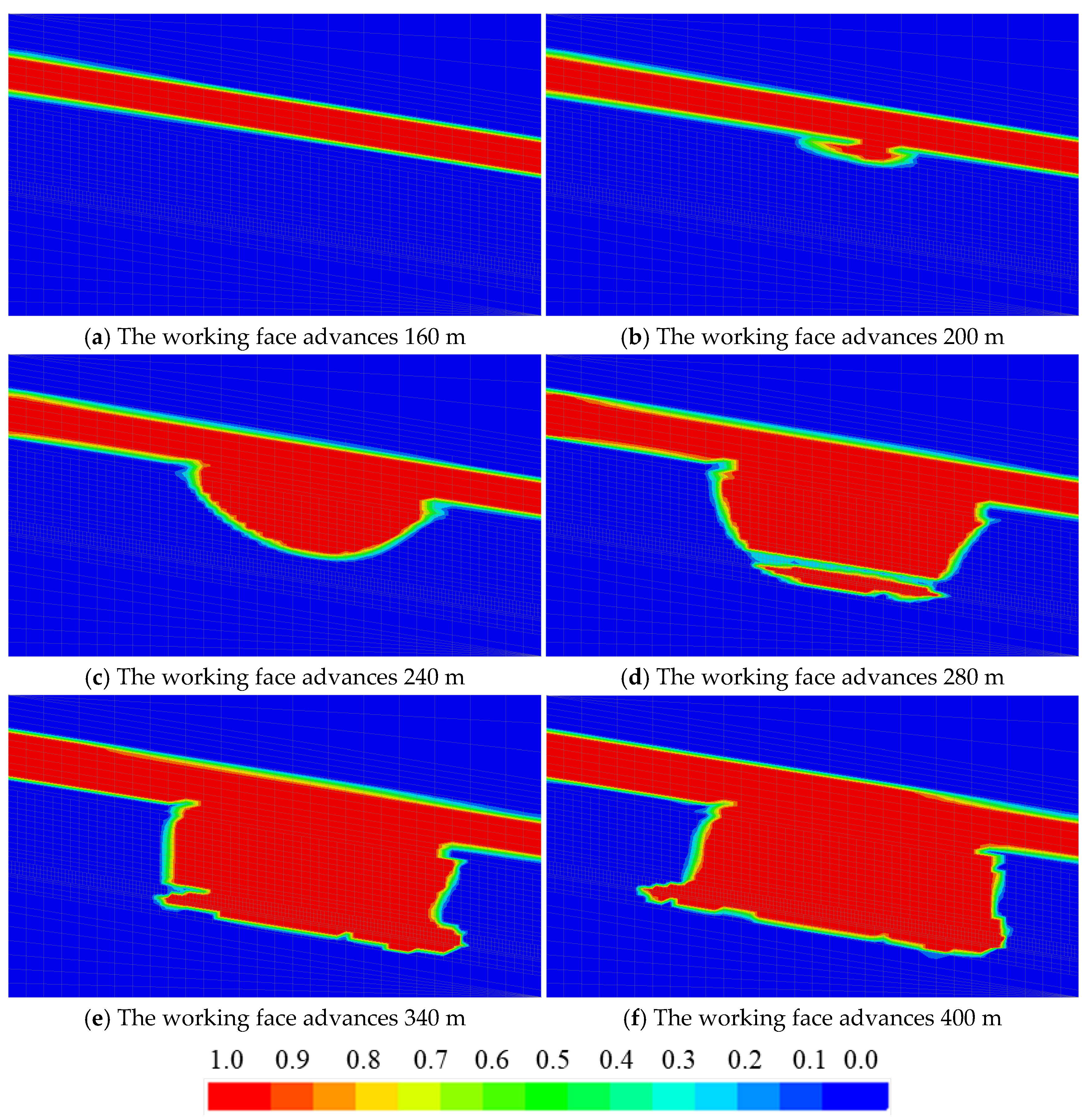
Figure 15 shows the saturation evolution characteristics at the location of the model dip X = 250 m slice during the advancement of the working face along the strike. From the simulation results, the plastic zone of the overburden strata gradually expands upwards as the working face advances and eventually connects with the upper aquifer, leading to water seepage. When advancing to 160 m, the plastic zone develops into the aquifer, meaning that the water-conducting fracture zone starts to affect the stability of the aquifer. At this time, the water flow seeps along the fracture to the goaf, forming a local seepage channel and posing a potential threat to the safety of the working face. When advancing to 250 m, due to further development of the fracture, water in the aquifer seeps into the goaf on a large scale, indicating that the pressurized water in the aquifer may have broken through the overburden barrier and entered the working face area. This process shows that the stability of the goaf is strongly influenced by aquifer seepage, which may lead to increased risk of a water breakout disaster.
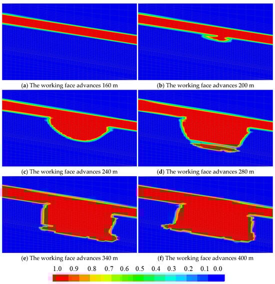
Figure 15.
Distribution characteristics of saturation along the dip of the working face.
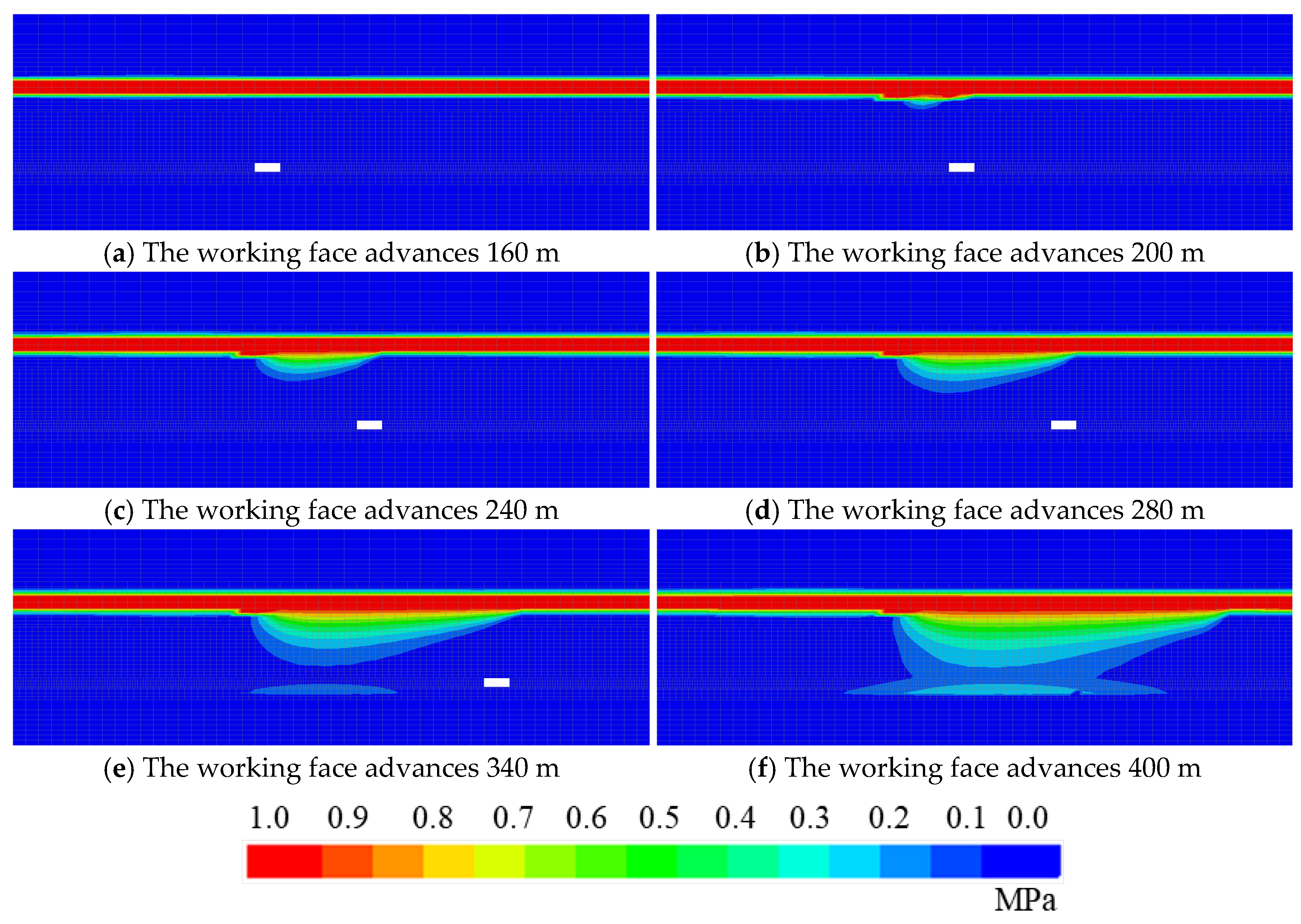
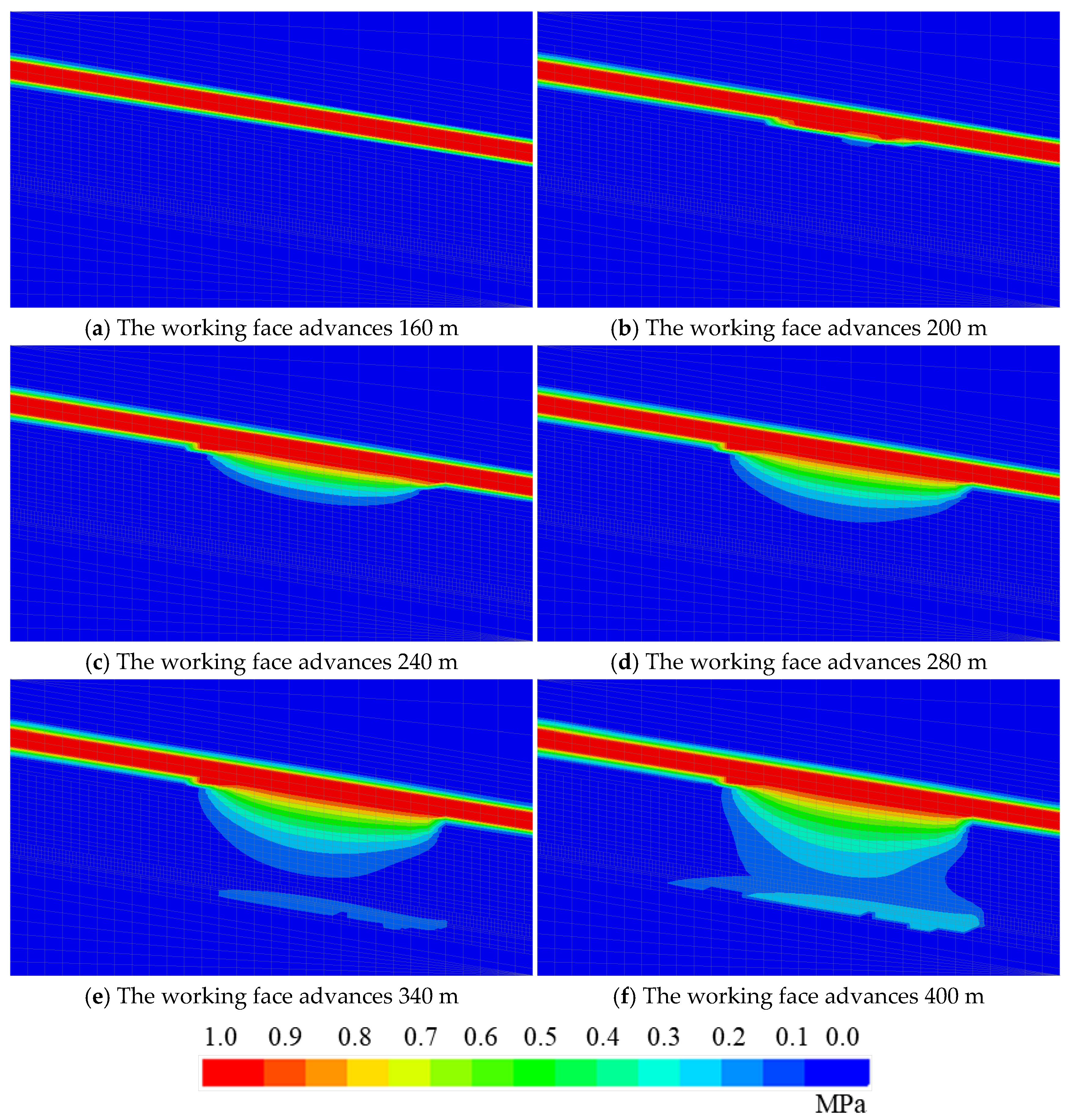
Figure 16 shows the evolution characteristics of the pore water pressure field at the location of the model dip X = 250 m slice during the advancement of the working face along the strike. From the evolutionary characteristics of pore water pressure, with the increase in advance distance the pore water pressure decreases significantly at the junction of the aquifer and fracture zone, which indicates that the water flow moves along the fracture to the low-pressure zone and forms a seepage field. This seepage may not only accelerate the collapse of the overburden strata but may also lead to a significant decline in the volume of water in the aquifer, with implications for the surrounding ecosystem. Therefore, during the advancement of the working face, The monitoring of the water-conducting fracture zone must be strengthened, and measures such as grouting reinforcement and pre-pumping of hydrophobic water must be taken to reduce the risk of water disaster and ensure the safe production of the mine.
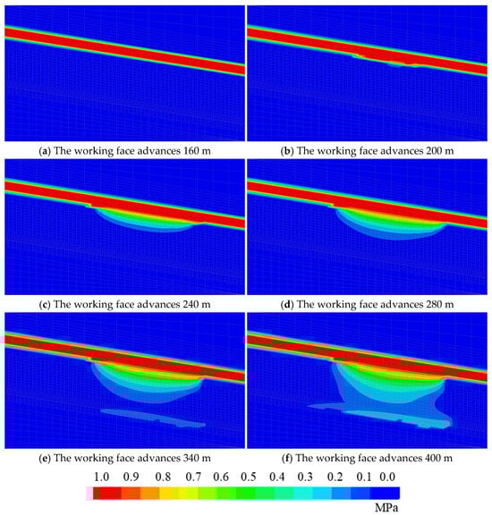
Figure 16.
Distribution characteristics of pore water pressure field along the dip of the working face.
The pore water pressure at different heights of the overburden strata shows an obvious trend at different advancing distances (Figure 17). In the early stage of advancement (0–100 m), the pore water pressure at all measurement points is close to zero, indicating that the overburden strata has not been disturbed by mining at this time, and the pore water pressure in the aquifer is kept in static equilibrium. However, as it advances to 120 m and above, especially after 140 m, the pore water pressure at some measurement points starts to increase, indicating that the WCFZ gradually expands upwards and starts to affect the aquifer area. At this stage, the pressure change of the measurement point at a low height (35.5 m) is not obvious, while the pressure of the measurement point at a higher height (50 m, 65 m) gradually increases, which reflects that the initial development of the fracture mainly affects the permeability of the higher area and that the water pressure of the aquifer has not been fully released. Entering the 260–320 m stage, there is an obvious surge in pore water pressure, especially in the low-level measurement points near the coal seam roof, indicating that the redistribution of stress in the goaf has drastically altered the structure of the overburden strata, allowing the water from the aquifer to penetrate into the overburden strata. At this stage, the pressure of the aquifer at 80 m decreased, reflecting the gradual formation of the trend of downward infiltration of water, and the further development of the fracture also increased the potential risk of mine water breakout. When advancing to 260 m and above, water damage monitoring must be strengthened, focusing on the fracture connectivity, and taking over-drainage measures to reduce the threat of water breakout. When the working face advances to 340 m and above, the pore water pressure shows drastic changes at each measuring point, indicating that the fracture expansion has basically connected the aquifer and the goaf, forming a more stable seepage channel.
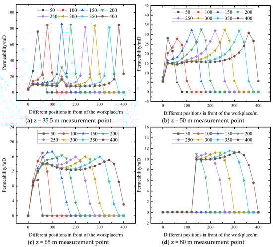
Figure 17.
Evolution of pore water pressure in the overburden strata under different advancement distances of the working face.
The pore water pressure at different heights of the overburden strata experienced four stages: static equilibrium, fracture expansion, seepage formation, and high risk of water breakout. The evolution process of pressure directly reflects the development state of fracture. To ensure safe mining, it is suggested that over-drilling be carried out when advancing beyond 200 m to assess fracture expansion. At the same time, pre-pumping hydrophobic, grouting reinforcement and other measures should be combined to reduce the aquifer pressure in advance to reduce the risk of water breakout, and to strengthen the drainage management when advancing to more than 300 m to cope with possible water breakout problems and ensure the safe production of the mine.
5. Conclusions
- (1)
- This study systematically investigated the coupled evolution mechanisms of stress–fracture–seepage fields in overburden strata through integrated experimental and numerical approaches. Laboratory triaxial permeability tests on three types of damaged coal rock samples (raw, fractured, and broken) revealed distinct seepage behaviors: fractured samples exhibited 23–48 times higher initial permeability (28.03 mD for coal, 13.54 mD for rock) compared to intact samples, while broken rock permeability decayed exponentially from 120.32 mD to 23.72 mD under compaction. These findings established quantitative permeability models (R2 > 0.99) that effectively characterize zonal differences in mining-induced damage, providing a critical experimental basis for multi-field coupling simulations.
- (2)
- A dynamic coupling methodology was developed by integrating FISH scripting with FLAC3D, enabling real-time permeability updates based on stress states and failure zone identification. The algorithm embedded three mechanisms: stress-dependent exponential decay for intact zones, yield-triggered permeability jumps for fractured regions, and compaction-driven nonlinear evolution for caved zones. This approach bridged the gap between static laboratory models and dynamic mining conditions, achieving automatic multi-field coupling during face advancement simulations.
- (3)
- Numerical simulations of the Luotuoshan 110,901 working face identified critical seepage thresholds and spatial patterns. High-permeability zones (5–15 × background values) persistently localized at goaf boundaries and fracture zones, with peak permeability (81.67 mD) occurring at 200 m advancement. The simulated fracture zone height reached 55 m, directly connecting with the overlying aquifer (9 m thick, 1 MPa pressure), consistent with field-measured water inrush events. These results demonstrated the method’s capability to predict water-conducting fracture development and optimize drainage strategies.
- (4)
- The stress–fracture–seepage coupling process evolved through four quantifiable stages: static equilibrium (0–100 m, <5 mD), fracture expansion (120–200 m, +484% permeability), seepage channel formation (200–300 m, aquifer connectivity), and high-risk inrush (300–400 m, 23.72 mD stabilized flow). These findings provide actionable thresholds for staged prevention measures—grouting before 200 m, targeted dewatering at 260–320 m, and enhanced drainage beyond 340 m. The methodology offers a predictive framework for deep mining water hazards, with future research recommended for multi-aquifer systems and real-time monitoring integration.
Author Contributions
Conceptualization, Y.L. and C.Z.; methodology, C.Z.; software, S.F.; validation, T.H., Y.G. and F.L.; formal analysis, S.F.; investigation, J.H.; resources, Y.L.; writing—original draft preparation, S.F.; writing—review and editing, C.Z.; visualization, S.F.; supervision, Y.L.; project administration, Y.G. All authors have read and agreed to the published version of the manuscript.
Funding
This research was funded by the 2022 First Batch of Science and Technology Projects of China Energy Group (GJNY-22-68), the Innovation Project of CCTEG Wuhan Research Institute (ZZYF202318), and the the National Key R&D Program of China (2023YFC3012101).
Data Availability Statement
Some or all data, models, or codes that support the findings of this study are available from the corresponding author upon reasonable request.
Conflicts of Interest
Authors Yan Liu, Tengfei Hu, and Fuzhong Li were employed by CCTEG Wuhan Engineering Company. Authors Yuan Guo and Jiawei Huang were employed by Luotuoshan Coal Mine of Wuhai Energy. The remaining authors declare that the research was conducted in the absence of any commercial or financial relationships that could be construed as a potential conflict of interest.
References
- Li, Q.; Li, Q.; Wu, J.; Li, X.; Li, H.; Cheng, Y. Wellhead stability during development process of hydrate reservoir in the Northern South China Sea: Evolution and mechanism. Processes 2024, 13, 40. [Google Scholar] [CrossRef]
- Han, P.; Wang, K.; Pang, J.; Ji, X.; Zhang, C. Response properties of geometries of coal penetrating fracture on seepage behavior. Int. J. Min. Sci. Technol. 2025, 35, 191–211. [Google Scholar] [CrossRef]
- Bai, E.; Guo, W.; Tan, Y.; Guo, M.; Wen, P.; Liu, Z.; Ma, Z.; Yang, W. Regional division and its criteria of mining fractures based on overburden critical failure. Sustainability 2022, 14, 5161. [Google Scholar] [CrossRef]
- Feng, D.; Hou, E.; Wang, S.; Xie, X.; Yuan, F.; Guo, L.; Wang, G.; Xie, Y.; Chen, Z. Research on 3D development characteristics of water-conducting fractured zone based on field measurement. Front. Earth Sci. 2022, 10, 808931. [Google Scholar] [CrossRef]
- Wang, L.; Zhang, W.; Cao, Z.; Xue, Y.; Liu, J.; Zhou, Y.; Duan, C.; Chen, T. Effect of weakening characteristics of mechanical properties of granite under the action of liquid nitrogen. Front. Ecol. Evol. 2023, 11, 1249617. [Google Scholar] [CrossRef]
- Xu, J.; Yang, D.; Zhang, Z.; Sun, Y.; Zhao, L. Study on fracture evolution and water-conducting fracture zone height beneath the sandstone fissure confined Aquifer. Sustainability 2024, 16, 6006. [Google Scholar] [CrossRef]
- Zhang, C.; Wang, X.; Han, P.; Zhang, T.; Zhang, L.; Wang, F. Acoustic emission and splitting surface roughness of sandstone in a Brazilian splitting test under the influence of water saturation. Eng. Geol. 2024, 329, 107369. [Google Scholar] [CrossRef]
- Wang, G.; Wu, M.; Wang, R.; Xu, H.; Song, X. Height of the mining-induced fractured zone above a coal face. Eng. Geol. 2017, 216, 140–152. [Google Scholar] [CrossRef]
- Liu, Q.; Huang, J.; Guo, Y.; Zhong, T. Research on the temporal-spatial evolution of ground pressure at short-distance coal seams. Arab. J. Geosci. 2020, 13, 1014. [Google Scholar] [CrossRef]
- Lu, C.; Xu, J.; Li, Q.; Zhao, H.; He, Y. Research on the development law of water-conducting fracture zone in the combined mining of jurassic and carboniferous coal seams. Appl. Sci. 2022, 12, 11178. [Google Scholar] [CrossRef]
- Su, B.Y.; Yue, J.H. Research of the electrical anisotropic characteristics of water-conducting fractured zones in coal seams. Appl. Geophys. 2017, 14, 216–224. [Google Scholar] [CrossRef]
- Wang, S.; Li, X.; Wang, D. Mining-induced void distribution and application in the hydro-thermal investigation and control of an underground coal fire: A case study. Process Saf. Environ. Prot. 2016, 102, 734–756. [Google Scholar] [CrossRef]
- Wang, H.; Zhang, D.; Wang, X.; Zhang, W. Visual exploration of the spatiotemporal evolution law of overburden failure and mining-induced fractures: A case study of the Wangjialing coal mine in China. Minerals 2017, 7, 35. [Google Scholar] [CrossRef]
- Li, X.; Li, Q.; Xu, X.; Zhao, Y.; Li, P. Multiple Influence Factor Sensitivity Analysis and Height Prediction of Water-Conducting Fracture Zone. Geofluids 2021, 2021, 8825906. [Google Scholar] [CrossRef]
- Zhang, D.; Gao, Y.; Zhang, G.; Tang, Z.; Ding, F.; Gao, M. Failure characteristics of overlying strata and mechanism of strong ground pressure during the large-scale and continuous mining of deep multi working faces. Energy Sci. Eng. 2024, 12, 4950–4964. [Google Scholar] [CrossRef]
- Wang, S.; Liu, K.; Wang, S.; Liang, Y.; Tian, F. Three-dimensional stochastic distribution characteristics of void fraction in longwall mining-disturbed overburden. Bull. Eng. Geol. Environ. 2022, 81, 414. [Google Scholar] [CrossRef]
- Jiang, D.; Tang, Y.; Huang, W.; Hou, K.; Luo, Y.; Liu, J. Research on the height of the water-conducting fracture zone in fully mechanized top coal caving face under combined-strata structure. Sustainability 2022, 14, 13781. [Google Scholar] [CrossRef]
- Wang, W.; Li, Z.; Du, F.; Cao, Z.; Li, G. Study of roof water inrush control technology and water resources utilization during coal mining in a Karst area. Mine Water Environ. 2023, 42, 546–559. [Google Scholar] [CrossRef]
- Yang, D.; Guo, W.; Tan, Y. Study on the Evolution Characteristics of Two-Zone Failure Mode of the Overburden Strata under Shallow Buried Thick Seam Mining. Adv. Civ. Eng. 2019, 2019, 9874769. [Google Scholar] [CrossRef]
- Ghabraie, B.; Ren, G.; Zhang, X.; Smith, J. Physical modelling of subsidence from sequential extraction of partially overlapping longwall panels and study of substrata movement characteristics. Int. J. Coal Geol. 2015, 140, 71–83. [Google Scholar] [CrossRef]
- Wang, C.; Zhang, C.; Li, Z.; Zhou, J. Using discrete element numerical simulation to determine effect of persistent fracture morphology on permeability stress sensitivity. Int. J. Numer. Anal. Methods Geomech. 2023, 47, 570–584. [Google Scholar] [CrossRef]
- Shi, X.; Zhang, J. Characteristics of overburden failure and fracture evolution in shallow buried working face with large mining height. Sustainability 2021, 13, 13775. [Google Scholar] [CrossRef]
- Dong, F.; Yin, H.; Ren, H.; Cheng, W.; Tai, S.; Miao, T.; Zhang, Y. Trapezoidal Failure Behavior and Fracture Evolution Mechanism of Overburden in Extra-thick Coal Mining in Weakly Cemented Strata. Rock Mech. Rock Eng. 2024, 57, 11239–11260. [Google Scholar] [CrossRef]
- Song, S.; Ruan, H.; Wei, J.; Niu, R.; Cheng, X.; Chen, B. The Influence of the Key Characteristics of Overburden Rock Structure on the Development Height of Water-Conducting Fracture in Yushenfu Coal Mine Area, China. Appl. Sci. 2024, 14, 10537. [Google Scholar] [CrossRef]
- Chang, X.; Wang, M.; Zhu, W.; Fan, J.; Liu, M. Study on height development characteristics of water-conducting fracture zone in fully mechanized mining of shallow thick coal seam under water. Sustainability 2023, 15, 7370. [Google Scholar] [CrossRef]
- Yang, B.; Yuan, S.; Liang, Y.; Liu, J. Investigation of overburden failure characteristics due to combined mining: Case study, Henan Province, China. Environ. Earth Sci. 2021, 80, 143. [Google Scholar] [CrossRef]
- He, X.; Zhang, C.; Han, P. Overburden Damage Degree-Based Optimization of High-Intensity Mining Parameters and Engineering Practices in China’s Western Mining Area. Geofluids 2020, 2020, 8889663. [Google Scholar] [CrossRef]
- Cao, Z.; Yang, X.; Li, Z.; Du, F. Evolution mechanism of water-conducting fractures in overburden under the influence of water-rich fault in underground coal mining. Sci. Rep. 2024, 14, 5081. [Google Scholar]
- Chen, K.; Ge, Y.; Liu, Z.; Chen, L.; Zhang, Q. Overburden failure associated with slicing mining in a super thick coal seam under special weak aquifers. Water 2022, 14, 3882. [Google Scholar] [CrossRef]
- Seidle, J.P.; Jeansonne, M.W.; Erickson, D.J. Application of matchstick geometry to stress dependent permeability in coals. In Proceedings of the SPE Rocky Mountain Regional Meeting, Casper, WY, USA, 18–21 May 1992; SPE: Richardson, TX, USA, 1992; p. 24361. [Google Scholar]
- Li, S.; Tang, D.; Pan, Z.; Xu, H.; Huang, W. Characterization of the stress sensitivity of pores for different rank coals by nuclear magnetic resonance. Fuel 2013, 111, 746–754. [Google Scholar] [CrossRef]
- Ahmadi, S.; Khormali, A.; Razmjooie, A. Experimental investigation on separation of water in crude oil emulsions using an oil-soluble demulsifier. Iran. J. Chem. Chem. Eng. 2023, 42, 2332–2343. [Google Scholar]


Disclaimer/Publisher’s Note: The statements, opinions and data contained in all publications are solely those of the individual author(s) and contributor(s) and not of MDPI and/or the editor(s). MDPI and/or the editor(s) disclaim responsibility for any injury to people or property resulting from any ideas, methods, instructions or products referred to in the content. |
© 2025 by the authors. Licensee MDPI, Basel, Switzerland. This article is an open access article distributed under the terms and conditions of the Creative Commons Attribution (CC BY) license (https://creativecommons.org/licenses/by/4.0/).