You are currently viewing a new version of our website. To view the old version click .
Processes
  • Article
  • Open Access

5 January 2025

Disassembly and Its Obstacles: Challenges Facing Remanufacturers of Lithium-Ion Traction Batteries

,
,
and
1
Chair Manufacturing and Remanufacturing Technology, University of Bayreuth, Universitaetsstrasse 30, 95447 Bayreuth, Germany
2
Bavarian Center for Battery Technology, Universitaetsstrasse 30, 95447 Bayreuth, Germany
3
Fraunhofer Institute for Manufacturing Engineering and Automation IPA, Universitaetsstrasse 9, 95447 Bayreuth, Germany
*
Author to whom correspondence should be addressed.
This article belongs to the Special Issue Green Manufacturing and Energy-Efficient Production

Abstract

Lithium-ion batteries are major drivers to decarbonize road traffic and electric power systems. With the rising number of electric vehicles comes an increasing number of lithium-ion batteries reaching their end of use. After their usage, several strategies, e.g., reuse, repurposing, remanufacturing, or material recycling can be applied. In this context, remanufacturing is the favored end-of-use strategy to enable a new use cycle of lithium-ion batteries and their components. The process of remanufacturing itself is the restoration of a used product to at least its original performance by disassembling, cleaning, sorting, reconditioning, and reassembling. Thereby, disassembly as the first step is a decisive process step, as it creates the foundation for all further steps in the process chain and significantly determines the economic feasibility of the remanufacturing process. The aim of the disassembly depth is the replacement of individual cells to replace the smallest possible deficient unit and not, as is currently the case, the entire battery module or even the entire battery system. Consequently, disassembly sequences are derived from a priority matrix, a disassembly graph is generated, and the obstacles to non-destructive cell replacement are analyzed for two lithium-ion traction battery systems, to analyze the distinctions between battery electric vehicle (BEV) and plug-in hybrid electric vehicle (PHEV) battery systems and identify the necessary tools and fundamental procedures required for the effective management of battery systems within the circular economy.

1. Introduction

1.1. Motivation

Due to steadily increasing greenhouse gas emissions and the associated risk of further exacerbating global climate change, transport and energy system targets include implementing alternative ways to store or buffer energy. The lithium-ion battery is the most successful competitor for these interests due to its high energy densities, high voltage, and wide range of chemistries with diverse electrode designs [1,2]. First utilized in consumer electronics in the 1980s, the lithium-ion battery gained a wide range of applications, like larger energy systems for traction and energy storage. However, the increasing number of utilized batteries also leads to a rising number of failed batteries and growing amounts of waste. Most car manufacturers have agreed on a battery warranty of 8 years and 160,000 km, while Lexus already offers a warranty of 10 years or 1 million km on its UX300e [3]. In 2023, global demand for lithium-ion batteries was expected to reach 718 GWh and is forecast to nearly double to 1329 GWh in 2025 and more than quadruple to 3127 GWh in 2030 [4,5]. Although there are several industrial processes to recycle lithium-ion batteries on the material level, a standardized industrial process to realize reuse or further use on the product level is still missing [6]. Due to the wide variety of cell chemistries, cell formats, and performance values, recycling on the material level is commonly preferred. Other, higher-level strategies like remanufacturing are only considered secondarily because of the complex interaction of economic and ecological parameters and safety concerns.
The key research of this study is on the second step of remanufacturing: disassembly. This process step is one of the more complex ones since work is carried out in the high-voltage range, and the cells themselves contain chemicals. Therefore, it is a time-consuming and costly process, which must be planned well to reduce the risks involved. At present, traction batteries are industrially dismantled only down to the module level, and no individual cell exchange takes place. To provide an overview of the disassembly process, the battery systems of the BMW X1 xDrive25e and the SMART EQ are examined in more detail. Followed by related research section, there is a brief overview and description of the circular economy, the structure of traction batteries and LIBs, and the derived End-of-Use/End-of-Life strategies with a special differentiation between remanufacturing and recycling. This step is followed by an analysis of disassembly illustrated by a disassembly priority matrix, the listing of required disassembly steps and tools, a disassembly priority graph, as well as the identification of mechanical obstacles to the exchange of individual cells. Finally, the findings are utilized to finalize the design of traction battery systems and to guide the design for remanufacturing.

1.2. Related Research

There have been several studies on the evaluation of the dismantlability for different product designs in general as well as for batteries in particular. For the purposes of categorization, these are compared with the scope of the present work. Accordingly, the criteria by which a relevant publication is considered to be related to the contents of this work are as follows:
IComparisonDoes the study compare different design possibilities?
IIDegree of DisassemblyHow deep is the disassembly of the LIB carried out?
IIIApplication case:
Battery
Are EV batteries the application case of the study?
IVYearHas the study been published recently?
VDisassembly performedAre purposeful disassembly analyses conducted to support the evaluation?
A study is considered appropriate to represent the state of research if it generally addresses the topic of disassembly and if it additionally addresses several of the criteria listed above. Table 1 provides an overview of the identified literature in the context of this publication.
Table 1. Highlighting of the main gaps in the literature, based on relevant criteria. The greater the degree of color filling of the circle, the higher the level of fulfilment of the respective criterion.
Gschwendtner and Kopacek (1996) [7] introduce the autodemograph method for assessing product designs for automated disassembly and recycling. The method applies a data structure designed to present essential information and includes the use of comparative indices. In a similar sense, Kroll and Carver (1999) [8] propose a method that is able to estimate design-specific manual disassembly times based on four distinctive criteria. These are the accessibility, positioning, the force required, and a base time criterion that is used as a general basis for estimating the time required to disassemble a certain type of joint. Desai and Mital (2003) [9] introduce a comprehensive methodology aimed at improving dismantlability through a systematic integration of disassembly considerations into product design. They facilitate quantitative evaluation by assigning numerical indices to design factors, thereby helping to identify disassembly challenges. Sodhi et al. (2004) [10] determine the unfastening effort by the introduction of an unfastening model through which the number of unfastening actions and the properties of the connecting machine elements are determined. Correction factors are then assigned to the respective properties, such as thread length or wrench width, and these are summed up to quantitatively describe the total effort for disassembly. Based on an existing approach, Herrmann and Raatz et al. (2012) [11], developed a catalogue of criteria to assess whether and to what extent the automation of a certain process is technically feasible. The authors apply this catalogue to the disassembly procedure of an existing battery and find the specific automation potentials for each disassembly step. A similar catalogue is applied in an adapted form by Hellmuth et al. (2021) [16], who investigate the disassembly processes for more recent battery designs and apply a more detailed quantification method. Weyrich and Natkunarajah (2013) [12] evaluate various systems for identifying the battery components and techniques for loosening the joints. From this, the authors developed a semi-automated disassembly approach using modular components with the possibility of establishing a fully automatic process. Different DfD methods and corresponding disassembly procedures for products are discussed by Soh et al. (2014) [13]. By considering disassembly constraints and requirements early in the design phase, products can be optimized for ease of disassembly, material recovery, and reuse of components and sub-assemblies. Rallo et al. (2020) [14], analyze the dismantling of LIBs using a Smart ForFour (Manufacturer: Accumotive GmbH, Kamenz, Germany), focusing on costs and remanufacturing advantages at different dismantling levels. While providing detailed process steps and times, the study does not consider cost efficiency analysis or the comparison of different LIB types. Detailed product design considerations regarding their automation possibilities in disassembly are considered by Blankemeyer et al. (2021) [15]. In their study, the authors classify the joint types present in lithium-ion batteries and support the design planning of an automated disassembly system based on prior product analysis. Their study concludes that a certain degree of uniformity in battery design would be beneficial but remains a challenge in the future. Lander et al. (2023) [18] investigate the differences in disassembly costs between five commercially available battery pack designs. In their analysis, they apply a combined techno-economic perspective to investigate the economic consequences of increased disassembly times. They apply joint type-specific time demand values that corresponding removal tasks would have and calculate the total time required for the different designs. They conclude that disassembly times are highly design-dependent and that at least partial automation could result in a significant reduction in disassembly costs. Sierra-Fonralvo et al. (2024) [20] introduce a diagnosis tool that identifies a product’s remanufacturing potential at the component level. They address the design-related dismantlability of the product and also consider its physical condition upon return. The first is calculated based on a dismantlability index. This index evaluates the type of joint to be unfastened, its accessibility and complexity, as well as its disassembly requirements, which include the necessity of specialized tools. Baazouzi et al. (2023) [19] developed a design for an adaptive disassembly planner. The tool is evaluated on a specific battery design (e.g., used in the Audi A3 Sportback Hybrid). Three decisions are combined: the optimal disassembly sequence, the optimal disassembly depth, and the optimal circular economy strategy. The tool can be used in the development phase, i.e., in the design of the batteries to advance automation with the tool. Rosenberg et al. (2022) [17] assess the duration of disassembly for a battery system under uncertainty applying a fuzzy logic approach. This serves as a basis to derive cost estimations and is supported with actual disassembly experiments.
Despite the growing focus on optimizing EoL processes for lithium-ion batteries, several gaps remain in the comparative evaluation and detailed analysis of individual battery component designs to facilitate automated disassembly. Key areas that require attention include the following:
-
There have been only a few detailed comparative evaluations of different batteries and none for battery components from different brands to assess the extent to which they facilitate disassembly.
-
There is a lack of structured analysis at the component level and comparisons of how they enable or hinder disassembly. Existing publications tend to summarize insights from a higher-level perspective, comparing whole battery packs without investigating the depth and sequence of disassembly processes.

2. Materials and Methods

In the following, the fundamentals of the circular economy as an ecological and economic lever and the structure of an LIB are described as background information. Furthermore, different End-of-Life strategies for LIBs and the associated challenges and risks are presented. Lastly, in Section 2.5, the developed methodology for optimizing disassembly sequences is explained.

2.1. Circular Economy

The circular economy aims to create value by managing resources already in the markets, contrary to the linear consumption system [21]. The Ellen McArthur Foundation describes the linear economy system as a “take-make-dispose” pattern [22]. Conversely, a circular economy targets critical economic and ecological weak points such as the depletion of natural raw materials and the final disposal of waste and recyclable materials [23]. Instead, resources that have already been used should be kept in the cycle as long as possible. This can be accomplished by waste management, establishing product reuse loops, closing material loops for the extended utilization of common materials in the same industry sector, and a well-connected industrial sector, in which potential waste is reused as input material for further processes [22]. The circular economy is characterized as a cascaded use or a cascading scheme that tries to maintain the value of products and materials [24]. System loop products and materials are cascaded as often as possible in the market, and only after all technological, economic, and ecological potentials have been exhausted is an energetic recovery considered. In conclusion, cascades are used from higher to lower levels of value retention.

2.2. Lithium-Ion Batteries

Lithium-ion batteries are increasingly gaining importance in the field of electro-mobility. They are also extensively used in mobile information and communication technologies (ICT) and, for example, in pedestrian-controlled electric power tools. On a smaller product scale, batteries in the electro-mobility sector are also increasingly used in pedelecs, electric bicycles, and electric scooters [25]. For automotive applications, lithium-ion batteries are integrated into electric vehicles, plug-in hybrids, and different forms of hybrid cars, but also in buses and trucks with built-in hybrid drive systems. In addition, they are used in stationary applications with a storage size from approximately 2 kWh up to 5 MWh [26].
Lithium-ion batteries are built hierarchically and are modular, in principle bringing advantages such as easier assembly and disassembly of individual components and simplified maintenance through the uncomplicated exchange of parts [26].
A lithium-ion battery consists of several modules, a heating/cooling unit, and a battery management system (BMS). The BMS quantifies and regulates electrical and thermal parameters necessary for efficient and low-maintenance lithium-ion battery operation. The modules themselves contain the electrical cells and subunits of the BMS for data transfer (e.g., state of charge (SoC), state of health (SoH), target, and actual values of temperature, voltage, and current) from every single module to the main unit. Three different cell formats are used: prismatic, cylindrical, and pouch cells. The selection of the cell format mainly depends on a suitable application and manufacturing costs. Different cell formats and cell chemistries suit diverse applications in terms of energy density, power density, safety, and overall costs [26,27].
These parameters are also determined by cell chemistry. Element compositions are shifting from lithium-cobalt-oxide (LCO) to lithium-nickel-manganese-cobalt-oxide (NMC) and lithium-nickel-cobalt-aluminum-oxide (NCA). The current effort is the transition towards higher nickel content to reduce the amount of cobalt being used while meeting expectations for higher energy and power densities. For low-cost batteries, a switch back to lithium-iron-phosphate (LFP) is expected due to their low material costs but high cycle performance [28,29].
To increase the electrical parameters like voltage or capacity and to suit the individual applications of the battery, the cells are electrically connected in series, parallel, or a superposition of both circuitries [28].

2.3. End-of-Use/End-of-Life Strategies

Several strategies can be used to close the loop of products and materials in a circular economy. These strategies are categorized and structured by various criteria like product condition and degree of necessary disassembly or further product use [4]. Potting et al. [30] differentiate between ten different strategies within the 9R Framework. Together with the BS 8887-2:2009, this will be used to determine and highlight remanufacturing. Since the favored goal is the lifespan extension of a product and its parts, the focus lies in R3 to R8, as shown in Table 2 [30,31].
Table 2. End-of-Use (EOU) and End-of-Life (EOL) strategies.
In the first step and regardless of the strategy, the lithium-ion battery is removed from the electric vehicle. It is commonly fastened to the underside of the car by bolts, which can be loosened with conventional or special tools [32]. All data collected from the BMS and other available data about the lithium-ion battery are transferred and analyzed in the second step. This includes data like cell chemistry/design, battery/thermal management information, past operating information, SoC, and SoH [33,34,35].
Remanufacturing is a process on an industrial level and consists of five individual steps: disassembly, cleaning, inspection, restoration, and reassembly [36,37]. It is performed when these significant processing steps are economical, and minor processes, like in the refurbish/recondition strategy, are not sufficient to meet the required performance level. The first process step is the disassembly of the lithium-ion battery, during which the modular design is exploited [38]. Depending on the associated disassembly effort and the benefit in total, the most economical degree of disassembly must be chosen. This can be a disassembly to the module or cell level, regarding the defective battery components, the kind of failure, or even market conditions. After exchanging these, all other worn parts can be replaced, depending on their condition. The remaining parts of the lithium-ion battery are cleaned and inspected for reuse [32,35,37,39]. Individual components that are graded as insufficient are replaced with either new spare parts or better-graded components out of other returned lithium-ion batteries. Finally, all parts are reassembled into the remanufactured lithium-ion battery and tested according to predetermined specifications [38,39]. The benefits of remanufacturing generally are an average of 80% to 90% savings in raw materials and energy and a price reduction of up to 40% [26,40].
Recycling, contrary to remanufacturing, targets the re-use or further use of the materials or substances only and does not preserve product components [30]. That is why a higher-value strategy like remanufacturing should always be preferred before destroying components to address material recycling processes [6]. Recycling includes three standard procedures or a combination to recover the used materials: hydrometallurgy, pyrometallurgy, and mechanical treatment, which differ mainly in the possible redeemed materials [33,39,41]. The significant advantage of recycling is the high flexibility to handle various lithium-ion batteries, cell chemistries, and cell formats.

2.4. General Dangers to the Remanufacturing of Lithium-Ion Batteries

The obstacles and dangers of remanufacturing can be generally divided into three categories: electrical, chemical, and thermal.
Voltages above the range of the protective low voltage, so-called high-voltage (>60 V and ≤1500 V (DC) or >30 V and ≤1000 V (AC)), pose a real danger. Electric vehicles and also traction batteries themselves are designed to be isolated, and the functionality of this isolation is permanently monitored. The high-voltage components of the vehicle are galvanically insulated from the low-voltage components on the one hand and designed in such a way that they can be touched without danger on the other. However, this changes as soon as you open the traction battery. The electrical contacts are exposed, and there is a risk of accidental touching. There is also the danger of creating a short circuit using tools, which can then lead to chemical and thermal hazards [42].
Short circuits caused by tools or that happen by penetrating the housing during destructive disassembly can lead to overheating of the cell when very high currents flow for a short time or longer. Apart from the thermal hazard (which will be explained in the next section), there is a risk of toxic substances being released due to overheating or unintentional penetration of the cell housing. The electrolyte is harmful to health not only when touched or ingested, but also due to the gases produced. The formation of hydrocarbons (HC), CO, and above all, hydrogen fluoride (HF) can occur. If hydrocarbons are released, there is a risk that the gas will be ignited by a spark (e.g., by a short circuit) and cause a flame burst or even an explosion depending on the gas concentration. During and after fires, hydrogen fluoride (HF) is formed. HF is a very toxic, corrosive, and highly reactive gas that causes severe or even fatal injuries on exposure. The basis for its formation is the salt LIPF6 used in the electrolyte. Any gas overpressure, such as the formation of HF or evaporating electrolyte due to overheating, is selectively released via pressure relief valves or rupture discs to prevent the entire cell or traction battery housing from bursting [42,43,44].
Lithium-ion cells have a certain operating range, which extends up to approx. 60 °C. If this limit temperature is exceeded, parasitic side reactions will occur. Overheating can have several origins, from incorrect charging to maintain the battery state of charge or a short circuit that generates heat due to the high currents to the absorption of heat energy by the destructive disassembly (e.g., drilling, cutting). Those side reactions are exothermal, further reinforcing the heat generation and, as a result, leading to a thermal runaway [42,45,46].

2.5. Methodology

The methodology for analysis is derived from [47] and structured into the following steps and was elaborated on two battery systems representative for the current state of the art: (1.) Disassembly of the battery system and documentation thereof, (2.) Creation of a parts list, (3.) Derivation of a priority matrix, (4.) Creation of list of disassembly steps and necessary tools, (5.) Disassembly graph. Each step is explained in more detail in the following.
1.
Disassembly of battery system and documentation thereof
A non-destructive disassembly from the system level down to the module level is examined. The disassembly is carried out up to both an economically feasible level, keeping in mind the range of available spare parts for battery systems, and a technologically necessary level to support further remanufacturing processes. For example, it is not necessary to disassemble a wiring harness, as it is replaced as a whole in case of a defect. For the disassembly, only standard tools are used. The disassembly process is documented with photos.
2.
Parts list
After the disassembly, an individual parts list has to be created, which is the basis for all the following steps.
3.
Priority matrix
After all the parts are identified, it is necessary to examine the relationships between them. These relationships indicate whether parts have priority over others and determine the order of the respective disassembly steps in an optimized disassembly sequence. The priority matrix is an appropriate method to analyze the relationships between parts and determine precedence relations. In the priority matrix, all parts are compared to each other one-on-one to determine which part must be disassembled first. Each part is assigned a value according to the following notation (Table 3). Assigning the components a value of −1, 0, or 1 enables the determination of the optimal sequence for their disassembly. By summing the row values associated with each component, the resulting totals provide the rank of each component. Components with higher sums are assigned a higher priority in the disassembly sequence:
Table 3. Value notation [29,30].
After the comparison, the positive scores are summed for each part. The total scores are then ranked, and the overall order of disassembly determined.
4.
List of disassembly steps and necessary tools
After determining the order of disassembly, all necessary disassembly tasks/steps have to be identified, and the required tools must be allocated to the tasks/steps.
5.
Disassembly graph
The results of the previous steps—priority matrix and disassembly list—are then combined, and a disassembly graph can be drawn. This graph links the precedence of parts to the individual disassembly tasks and gives a proper overview of the disassembly as a whole.

3. Results

In this section, the application of the developed methodology is demonstrated using two exemplary battery systems—employed in a BMW F48 X1 xDrive25e and a SMART EQ.

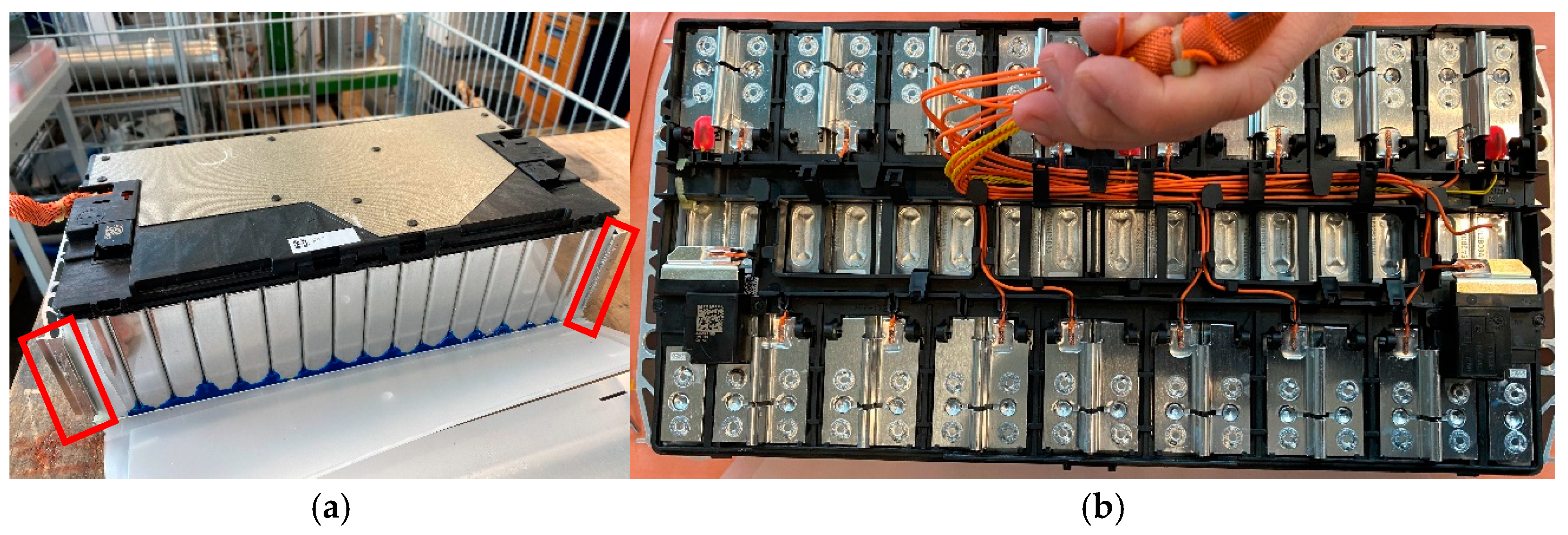
3.1. Disassembly to Module Level of the BMW F48 X1 xDrive25e

The following section describes the disassembly of the BMW F48 X1 xDrive25e battery system (Manufacturer: BMW AG, Germany) down to the module level. As explained before, the disassembly is carried out manually using isolated hand tools. Table 4 lists all parts into which the system could be disassembled, and Figure 1 shows them.
Table 4. Item list for the BMW F48 X1 xDrive25e.
Figure 1. Main components of the BMW F48 X1 xDrive25e numbered and named in Table 4.
The insights gathered during the disassembly allow the determination of the precedence relations among the parts and the creation of the priority matrix, which is shown in Table 5. Once the cover is removed, the safety box, battery management unit, and cell module 1 are all accessible, and there is no precedence between them. After disassembling these parts, the top shelf has to be removed to access the covered cell modules 2 and 3. Once the modules 2 and 3 are removed, the top cooler and then the bottom shelf and LV wiring harness can be disassembled. Now, the last two modules are accessible, and there is no mandatory sequence for removing them. The last steps are to disassemble the bottom cooler, HV cable plus and minus, and HV connector in this sequence.
Table 5. Disassembly matrix for the BMW F48 X1 xDrive25e.
Table 6 lists the activities that had to be performed and the tools required for each activity in more detail.
Table 6. Disassembly steps and necessary tools for the SMART EQ battery system.
Figure 2 gives an overview of the sequence of all activities, thus showing which activities do not have any precedence over each other and could be parallelized. For example, there is no fixed sequence for the disassembly of cell module 1 (III, VII, VIII), safety box (IV, V), and battery management unit (VI). In Table 6, these parts are removed in the following order: safety box, battery management unit, cell module 1; however, any other or parallelization of the steps is possible. The same holds for the activities (XIV, XV) and (XXI, XXII).
Figure 2. Disassembly priority graph for the BMW F48 X1 xDrive25e.

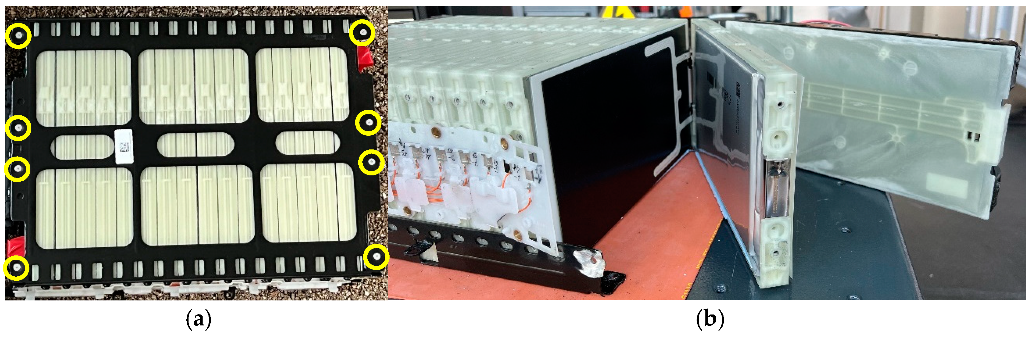
3.2. Disassembly to Module Level of the SMART EQ

In this section, the disassembly of the SMART EQ battery (Manufacturer: AccuMotive GmbH, Germany) is described down to the module level. All individual steps are performed manually with the help of isolated hand tools. The recovered modules are then examined for the possibility of separating the individual cells in the next step. The following Table 7 contains the names and numbers of the components belonging to the SMART EQ battery system, which are also depicted in Figure 3.
Table 7. Item list for the SMART EQ battery system.
Figure 3. Main components of the SMART EQ battery system.
The disassembly matrix can be seen in Table 8. It should be noted that after removing the cover, all high-voltage connections are first disconnected to eliminate the danger of high voltage. After a few more steps, all cell modules are equally accessible for removal. Taking the subsequent Table 9 into the consideration, it is shown that no special tools are needed for the individual disassembly steps.
Table 8. Disassembly matrix for the Smart EQ.
Table 9. Disassembly steps and necessary tools.
As listed in Table 9, starting with the loosening and removal of all screws on the top of the housing, the cover can be taken off. The next step is the disconnection of the HV and LV Connectors. Then, the rest of the live cables and rails are disconnected. After that, the HV and LV Connectors can be removed and by disconnecting and removing all remaining plugs belonging to the LV wiring harness, the cell modules are free to remove. It should be mentioned that unscrewing the cell modules themselves is difficult, as the insulated tools are too bulky to gain access through the gaps where the bolts are located, and the thermal paste on the bottom requires considerable force to detach the modules from the system base.
As depicted in Figure 4, steps I to X have a fixed sequence to access the parts following the matrix and to avoid the safety risks of the high voltage. Since the coolers are attached to the outside and underside of the housing, they can be removed at any time without performing any other disassembly steps first, but the battery system needs to be turned around to reach the necessary bolts.
Figure 4. Disassembly priority graph.
The analysis has shown that the disassembly down to the module level does not present any significant obstacles. However, this changes when disassembling to the cell level.

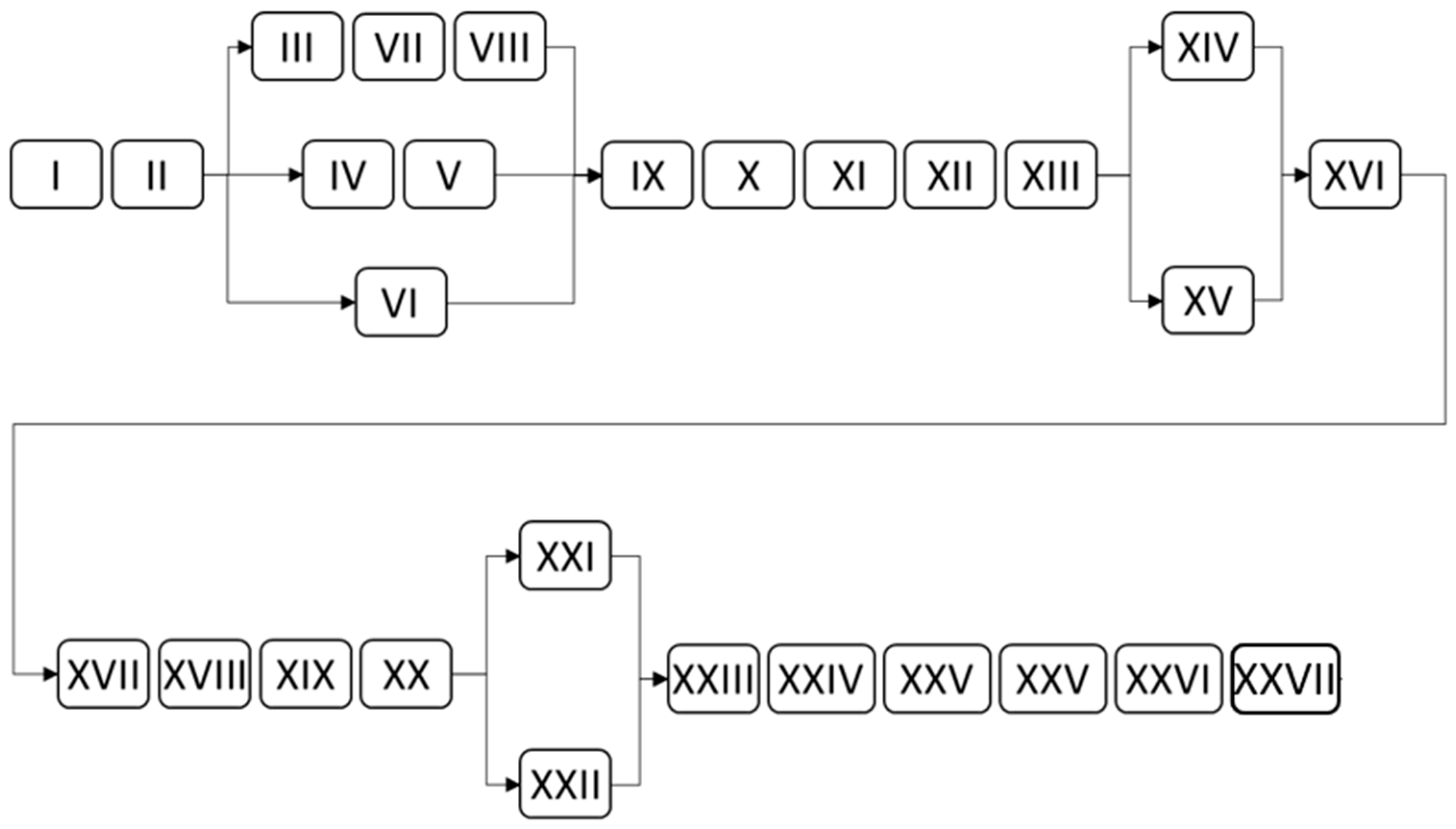
3.3. Disassembly to Cell Level of the BMW F48 X1 xDrive25e

The cells of the BMW are housed in a welded aluminum case. As you can see in Figure 5, the weld seams are marked in red. The cells themselves are cast at the bottom with a blue mass and glued to each other over the entire surface. The contact is realized by spot welding. To separate this structure, an angle grinder or a chisel/hammer is needed. To separate the individual prismatic cells, a wooden wedge was employed to create spacing between them, enabling the disassembly of the cell cluster and isolation of the individual cells. Following this, the charge levels were controlled, and the poles were short-circuited to ensure deep discharge. Subsequently, a prismatic cell was opened within a glove box using a metal saw to extract the electrode stack.
Figure 5. BMW F48 xDrive25e battery module. (a) The red rectangles mark the opened weld seams. (b) Spot-welded contacts and the partially removed wiring harness (voltage/current and temperature sensors).

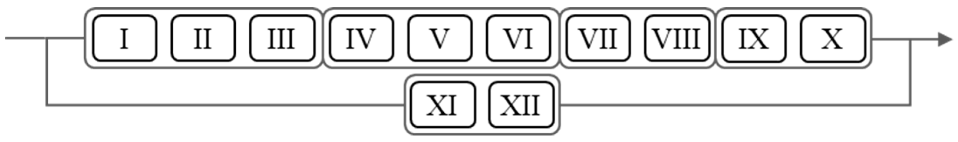
3.4. Disassembly to Cell Level of the SMART EQ

The cells of the SMART EQ battery module are enclosed by a metal cage, which is secured by rivets. These rivets are harder than the cage material. Removing them is not possible by blasting, as they are countersunk, and it is only possible to drill them out using a carbide drill and a drill press. The closed and opened module can be seen in Figure 6. A cutter is required to separate the individual cells. The pouch cells of the module were carefully removed from their plastic frames. Subsequently, the charge levels of the cells were measured, and the poles were short-circuited to ensure complete discharge. Within a glove box, a pouch cell was then opened using a precision cutting tool to extract the electrode stack.
Figure 6. SMART EQ battery module. (a) Module housing with yellow rings marking the rivets. (b) Opened module housing and unfanned cells.

4. Discussion

The analysis shows differences in the complexity of disassembly. On the one hand, the one-level SMART EQ battery system has fewer steps and you can reach the individual parts faster, while on the other hand, the two-level BMW battery system requires more steps to reach the parts in the system base. In addition, different screw heads and the accessibility of these require a tool change and an approach from different sides for both systems. While the cooler of the BMW battery system has to be removed in several steps, it is easily accessible. The cooler of the SMART EQ battery system can be removed at any time, but you have to turn the battery system upside down. While it is still possible to disassemble down to the module level without major difficulties, this changes as soon as you want to disassemble individual cells. As already described, the simple exchange/disassembly of/to individual cells would enable economically and ecologically higher circular economy options and also provide higher-quality materials for recycling, since the obstacles associated with complex separation steps would be resolved. The identified obstacles make the separation of parts not only complex but also dangerous for the operator and therefore costly for the whole process.
The comparison highlights significant design differences between BEV and PHEV battery systems. A closer examination of the PHEV battery system in a BMW, for example, underscores how the hybrid nature of the vehicle, which includes both an internal combustion engine and an electric powertrain, influences the battery design. In this case, the battery system is installed in the space made available by reducing the size of the fuel tank, which has been halved to accommodate the battery. Consequently, the battery system is designed with a multi-level arrangement of battery modules, as opposed to the single-level configuration typically found in BEVs. Furthermore, the cooling system for the PHEV battery utilizes refrigerant, integrating the cooling circuit already present for the combustion engine.
With respect to Rallo et al. [14], it is possible to estimate the cost of replacing individual parts in a SMART ForFour in terms of working hours. The optimized disassembly sequence enables the identification of the necessary steps to access components that may be defective or impair the performance of the battery system. As a result, the costs associated with targeted disassembly can be estimated by measuring the time and tools required, as well as by optimizing the disassembly sequence to improve efficiency.

5. Conclusions

Electric mobility is a relatively new and rapidly evolving technology, which explains the high degree of heterogeneity in current battery designs available on the market. Many technological challenges remain, with significant potential for improvement in areas such as energy density and charging speed. Consequently, these performance requirements often take precedence in product development over considerations for disassembly-oriented design. This prioritization results in high disassembly efforts and hinders the optimization of the disassembly process.
The study has shown that it is possible to disassemble the two market-available battery systems down to their electrode materials and to analyze the necessary steps and obstacles for efficient and safe disassembly.
A methodology for evaluating the most suitable circular economy option based on optimal economic and environmental outcomes was conducted. Given that dismantling is a critical step in each option, it is essential to determine the optimal sequence and calculate the associated effort for each work step, as well as the investment costs for tools and equipment. Consequently, this represents the initial step in identifying additional factors that may influence the efficiency of the disassembly process. Though this approach helps with optimizing the disassembly sequence and hence reducing time and cost, it involves a great deal of preparation effort, as the predecessors and successors have to be manually identified for each battery system individually by means of disassembly tests. Future work will quantify all process steps, expenses, and additional dismantling requirements for identified obstacles to present a detailed overview of all associated costs. Different battery formats and types will be studied. Individual module and cell testing regarding their performance values will be executed and linked to the necessary effort and time consumption. This will be brought into context with the disassembly effort to better capitalize on the modular design of lithium-ion batteries. Process chains for remanufacturing several traction batteries will be developed and optimized for ecological and economic goals.

Author Contributions

Conceptualization, G.O.; methodology, G.O.; validation, G.O.; investigation, G.O.; resources, G.O.; data curation, G.O.; writing—original draft preparation, G.O. and M.B.; writing—review and editing, G.O., B.R., and F.D.; visualization, G.O. and M.B.; project administration, B.R. and F.D.; funding acquisition, B.R. and F.D. All authors have read and agreed to the published version of the manuscript.

Funding

This research is based on a project funded by the German Federal Ministry of Education and Research, grant number 03XP0318C.

Data Availability Statement

The data that support the findings of this study are available from the corresponding author, G.O., upon reasonable request.

Conflicts of Interest

The authors declare no conflicts of interest.

References

  1. Kim, T.; Song, W.; Son, D.-Y.; Ono, L.K.; Qi, Y. Lithium-ion batteries: Outlook on present, future, and hybridized technologies. J. Mater. Chem. A 2019, 7, 2942–2964. [Google Scholar] [CrossRef]
  2. Wu, W.; Yang, X.; Zhang, G.; Chen, K.; Wang, S. Experimental investigation on the thermal performance of heat pipe-assisted phase change material based battery thermal management system. Energy Convers. Manag. 2017, 138, 486–492. [Google Scholar] [CrossRef]
  3. Zwicker, M.; Moghadam, M.; Zhang, W.; Nielsen, C.V. Automotive battery pack manufacturing—A review of battery to tab joining. J. Adv. Join. Process. 2020, 1, 100017. [Google Scholar] [CrossRef]
  4. Becker, J.; Beverungen, D.; Winter, M.; Menne, S. Umwidmung und Weiterverwendung von Traktionsbatterien; Springer Fachmedien Wiesbaden: Wiesbaden, Germany, 2019; ISBN 978-3-658-21020-5. [Google Scholar]
  5. Roland Berger. The Lithium Ion (EV) Battery Market and Supply Chain: Market Drivers and Emerging Supply Chain Risks; Roland Berger: Mumbai, India, 2022. [Google Scholar]
  6. Harper, G.; Sommerville, R.; Kendrick, E.; Driscoll, L.; Slater, P.; Stolkin, R.; Walton, A.; Christensen, P.; Heidrich, O.; Lambert, S.; et al. Recycling lithium-ion batteries from electric vehicles. Nature 2019, 575, 75–86. [Google Scholar] [CrossRef] [PubMed]
  7. Gschwendtner, G.; Kopacek, P. A New Method for the Assessment of Products for Automated Disassembling. IFAC Proc. Vol. 1996, 29, 748–753. [Google Scholar] [CrossRef]
  8. Kroll, E.; Hanft, T.A. Quantitative evaluation of product disassembly for recycling. Res. Eng. Des. 1998, 10, 1–14. [Google Scholar] [CrossRef]
  9. Desai, A.; Mital, A. Evaluation of disassemblability to enable design for disassembly in mass production. Int. J. Ind. Ergon. 2003, 32, 265–281. [Google Scholar] [CrossRef]
  10. Sodhi, R.; Sonnenberg, M.; Das, S. Evaluating the unfastening effort in design for disassembly and serviceability. J. Eng. Des. 2004, 15, 69–90. [Google Scholar] [CrossRef]
  11. Herrmann, C.; Raatz, A.; Mennenga, M.; Schmitt, J.; Andrew, S. Assessment of Automation Potentials for the Disassembly of Automotive Lithium Ion Battery Systems. In Leveraging Technology for a Sustainable World, Proceedings of the 19th CIRP Conference on Life Cycle Engineering, University of California at Berkeley, Berkeley, NJ, USA, 23–25 May 2012; Dornfeld, D.A., Ed.; LCE 2012; Springer: Berlin/Heidelberg, Germany, 2012; ISBN 364229068X. [Google Scholar]
  12. Weyrich, M.; Natkunarajah, N. Conception of an automated plant for the disassembly of lithium-ion batteries. In Proceedings of the 6th International Conference on Life Cyle Management (LCM), Gothenburg, Sweden, 25–28 August 2013. [Google Scholar]
  13. Soh, S.L.; Ong, S.K.; Nee, A. Design for Disassembly for Remanufacturing: Methodology and Technology. Procedia CIRP 2014, 15, 407–412. [Google Scholar] [CrossRef]
  14. Rallo, H.; Benveniste, G.; Gestoso, I.; Amante, B. Economic analysis of the disassembling activities to the reuse of electric vehicles Li-ion batteries. Resources, Conserv. Recycl. 2020, 159, 104785. [Google Scholar] [CrossRef]
  15. Blankemeyer, S.; Wiens, D.; Wiese, T.; Raatz, A.; Kara, S. Investigation of the potential for an automated disassembly process of BEV batteries. Procedia CIRP 2021, 98, 559–564. [Google Scholar] [CrossRef]
  16. Hellmuth, J.F.; DiFilippo, N.M.; Jouaneh, M.K. Assessment of the automation potential of electric vehicle battery disassembly. J. Manuf. Syst. 2021, 59, 398–412. [Google Scholar] [CrossRef]
  17. Rosenberg, S.; Huster, S.; Baazouzi, S.; Glöser-Chahoud, S.; Al Assadi, A.; Schultmann, F. Field Study and Multimethod Analysis of an EV Battery System Disassembly. Energies 2022, 15, 5324. [Google Scholar] [CrossRef]
  18. Lander, L.; Tagnon, C.; Nguyen-Tien, V.; Kendrick, E.; Elliott, R.J.; Abbott, A.P.; Edge, J.S.; Offer, G.J. Breaking it down: A techno-economic assessment of the impact of battery pack design on disassembly costs. Appl. Energy 2023, 331, 120437. [Google Scholar] [CrossRef]
  19. Baazouzi, S.; Grimm, J.; Birke, K.P. Multi-Method Model for the Investigation of Disassembly Scenarios for Electric Vehicle Batteries. Batteries 2023, 9, 587. [Google Scholar] [CrossRef]
  20. Sierra-Fontalvo, L.; Polo-Cardozo, J.; Maury-Ramírez, H.; Mesa, J.A. Diagnosing remanufacture potential at product-component level: A disassemblability and integrity approach. Resour. Conserv. Recycl. 2024, 205, 107529. [Google Scholar] [CrossRef]
  21. Lacy, P.; Rutqvist, J. Waste to Wealth; Palgrave Macmillan UK: London, UK, 2015; ISBN 978-1-349-58040-8. [Google Scholar]
  22. Ellen MacArthur Foundation. Towards the Circular Economy Vol. 1: An Economic and Business Rationale for an Accelerated Transition; Ellen MacArthur Foundation: Isle of Wight, UK, 2013. [Google Scholar]
  23. Haas, W.; Krausmann, F.; Wiedenhofer, D.; Heinz, M. How Circular is the Global Economy?: An Assessment of Material Flows, Waste Production, and Recycling in the European Union and the World in 2005. J. Ind. Ecol. 2015, 19, 765–777. [Google Scholar] [CrossRef]
  24. Russell, J.; Nasr, N. Value-Retention Processes within the Circular Economy. In Remanufacturing in the Circular Economy; Nasr, N., Ed.; Wiley: Hoboken, NJ, USA, 2019; pp. 1–29. ISBN 9781118414101. [Google Scholar]
  25. Promi, A.; Meyer, K.; Ghosh, R.; Lin, F. Advancing electric mobility with lithium-ion batteries: A materials and sustainability perspective. MRS Bull. 2024, 49, 697–707. [Google Scholar] [CrossRef]
  26. Korthauer, R. Handbuch Lithium-Ionen-Batterien; Springer: Berlin/Heidelberg, Germany, 2013; ISBN 978-3-642-30652-5. [Google Scholar]
  27. VDI Zentrum Ressourceneffizienz GmbH. Ressourceneffizienz Durch Remanufacturing—Industrielle Aufarbeitung von Altteilen; VDI Zentrum Ressourceneffizienz GmbH: Berlin, Germany, 2017. [Google Scholar]
  28. Jocher, P.; Steinhardt, M.; Ludwig, S.; Schindler, M.; Martin, J.; Jossen, A. A novel measurement technique for parallel-connected lithium-ion cells with controllable interconnection resistance. J. Power Sources 2021, 503, 230030. [Google Scholar] [CrossRef]
  29. Miao, Y.; Hynan, P.; von Jouanne, A.; Yokochi, A. Current Li-Ion Battery Technologies in Electric Vehicles and Opportunities for Advancements. Energies 2019, 12, 1074. [Google Scholar] [CrossRef]
  30. Potting, J.; Hekkert, M.P.; Worrell, E.; Hanemaaijer, A. Circular Economy: Measuring innovation in the product chain. Planbur. Voor De Leefomgeving 2017. [Google Scholar]
  31. British Standards Institution. Design for Manufacture, Assembly, Disassembly and End-Of-Life Processing (MADE) Part 2 Terms and Definitions British Standards Institution; British Standards Institution: London, UK, 2009; ISBN 9780580632853. [Google Scholar]
  32. Kampker, A. Elektromobilproduktion; Springer: Berlin/Heidelberg, Germany, 2014; ISBN 978-3-642-42021-4. [Google Scholar]
  33. Baltac, S.; Slater, S. Batteries on Wheels: The Role of Battery Electric Cars in the EU Power System and Beyond. Available online: https://www.transportenvironment.org/uploads/files/2019_06_Element_Energy_Batteries_on_wheels_Public_report.pdf (accessed on 19. November 2024).
  34. Beverungen, D. (Ed.) Dienstleistungsinnovationen für Elektromobilität: Märkte, Geschäftsmodelle, Kooperationen; [DELFIN—Dienstleistungen für Elekromobilität—Förderung von Innovation und Nutzerorientierung]; Gefördert vom Bundesministerium für Bildung und Forschung; [Laufzeit: 1 May 2013–31 October 2015]; Fraunhofer-Verl.: Stuttgart, Germany, 2015; ISBN 3839608430. [Google Scholar]
  35. Zhang, H.; Liu, W.; Dong, Y.; Zhang, H.; Chen, H. A Method for Pre-determining the Optimal Remanufacturing Point of Lithium ion Batteries. Procedia CIRP 2014, 15, 218–222. [Google Scholar] [CrossRef]
  36. Charter, M.; Gray, C. Remanufacturing and product design. Int. J. Prod. Dev. 2008, 6, 375–392. [Google Scholar] [CrossRef]
  37. Steinhilper, R. Produktrecycling: Vielfachnutzen Durch Mehrfachnutzung; Fraunhofer-IRB-Verl.: Stuttgart, Germany, 1999; ISBN 3816753078. [Google Scholar]
  38. Standridge, C.R.; Corneal, L. Remanufacturing, Repurposing, and Recycling of Post-Vehicle-Application Lithium-Ion Batteries; Tech Report United States; Mineta National Transit research Consortium: San Jose, CA, USA, 2014. [Google Scholar]
  39. Kampker, A.; Vallée, D.; Schnettler, A. Elektromobilität; Springer: Berlin/Heidelberg, Germany, 2018; ISBN 978-3-662-53136-5. [Google Scholar]
  40. Colledani, M.; Battaïa, O. A decision support system to manage the quality of End-of-Life products in disassembly systems. CIRP Ann. 2016, 65, 41–44. [Google Scholar] [CrossRef]
  41. Hanisch, C.; Haselrieder, W.; Kwade, A. Recycling von Lithium-Ionen-Batterien—Das Projekt LithoRec. Recycl. Und Rohst. 2012, 5, 691–698. [Google Scholar]
  42. Geisbauer, C.; Wöhrl, K.; Lott, S.; Nebl, C.; Schweiger, H.-G.; Goertz, R.; Kubjatko, T. Scenarios Involving Accident-Damaged Electric Vehicles. Transp. Res. Procedia 2021, 55, 1484–1489. [Google Scholar] [CrossRef]
  43. Akademie des Deutschen Kraftfahrzeuggewerbes GmbH. Handbuch zur Schulung von Fachkundigen für Arbeiten an HV-eigensicheren Systemen: Hybridfahrzeuge, Elektrofahrzeuge, Brennstoffzellenfahrzeuge; Vogel Buchverlag: Würzburg, Germany, 2011. [Google Scholar]
  44. Larsson, F.; Bertilsson, S.; Furlani, M.; Albinsson, I.; Mellander, B.-E. Gas explosions and thermal runaways during external heating abuse of commercial lithium-ion graphite-LiCoO2 cells at different levels of ageing. J. Power Sources 2018, 373, 220–231. [Google Scholar] [CrossRef]
  45. Brown, M.; Hilton, M.; Crossette, S.; Horton, I.; Hickman, M.; Mason, R.; Brown, A. Cutting Lithium-Ion Battery Fires in the Waste Industry; Eunomia Research & Consulting: Bristol, UK, 2021; Available online: https://qna.files.parliament.uk/qna-attachments/1625088/original/Waste-Fires-Caused-by-Li-ion-Batteries_FINAL-amended-w0l4kc.pdf (accessed on 19. November 2024).
  46. Gassmann, M. Akku-Packs Können Wie Eine BOMBE Hochgehen. Available online: https://www.welt.de/wirtschaft/article128500300/Akku-Packs-koennen-wie-eine-Bombe-hochgehen.html (accessed on 19. November 2024).
  47. Wegener, K.; Andrew, S.; Raatz, A.; Dröder, K.; Herrmann, C. Disassembly of Electric Vehicle Batteries Using the Example of the Audi Q5 Hybrid System. Procedia CIRP 2014, 23, 155–160. [Google Scholar] [CrossRef]
Disclaimer/Publisher’s Note: The statements, opinions and data contained in all publications are solely those of the individual author(s) and contributor(s) and not of MDPI and/or the editor(s). MDPI and/or the editor(s) disclaim responsibility for any injury to people or property resulting from any ideas, methods, instructions or products referred to in the content.

Article Metrics

Citations

Article Access Statistics

Multiple requests from the same IP address are counted as one view.