Abstract
In this paper, a closed hydrostatic drive powertrain (HSDP) composed of an engine, a variable pump, a variable motor, and an energy-efficient adaptive speed-regulating controller (ADC) based on power following is proposed and investigated. The controller can more than guarantee accurate regulation of motor speed through online efficiency estimation based on established loss models of the pump and the motor. It also facilitates the optimal efficiency control of the engine and hydrostatic system through two redundant control freedoms of the HSDP system, making an energy-saving adjustment of the motor speed. At the same time, the controller can prevent engine overload stall and high system pressure by limiting the displacement of the pumps and motors in real time based on the system loads to improve the automatic adaptability of the system to varying loads. Field testing experiments performed by means of a heavy transportation vehicle under different conditions were conducted to verify the efficacy of the proposed controller. The results showed that the average errors of motor speed were 3.3% under empty load conditions and 9.6% under heavy load conditions. In terms of energy saving, comparison tests involving a rule-based controller (RBC) and the ADC were carried out, and the results showed that the energy-saving ratio of the ADC was at least 11.5% and up to 25.8% under empty load conditions and at least 2.8% and up to 9% under heavy load conditions. The ADC controller showed good performance in terms of speed control, load adaptability, and energy saving and a superior advantage due to its simple structure and ease of implementation. Therefore, the proposed controller is an excellent choice for the real-time control of machinery with an HSDP system, especially heavy-duty machinery.
1. Introduction
A pump-controlled motor closed hydrostatic drive powertrain (HSDP) is a common technology used for rotary drives. Due to their advantages in terms of high power density, self-lubrication, simple overload protection, and wide speed regulation range, HSDPs have been widely applied to industrial and construction-related fields [1], such as in heavy manipulators [2], shield machines [3], wheel loaders [4], and heavy transportation vehicles [5]. However, they have also been criticized for their low efficiency and poor emission characteristics [6]. Currently, with the aim of energy saving and emission reduction, energy-saving research on powertrains has attracted great attention from host manufacturers and academic researchers around the world. The use of hybrid power, such as that produced by hydraulic hybrids [7,8], electric hybrids [9], electrohydraulic hybrids [10,11,12], is one of the main methods for improving the efficiency of powertrains. Its core principle is to adopt the existing or added control freedom of a system to allow the prime mover (engine or electric motor) to work in its high-efficiency region, thus improving the overall efficiency of the transmission system. For example, Ge et al. facilitated the decoupling control of flow and pump speed through an electrohydraulic power source with variable speed and variable displacement and proposed a strategy of segmented speed and continuous displacement adjustment based on redundant freedom to meet the energy-saving regulation on output flow [13,14]. Wang et al. designed a power split hydraulic torque converter to replace the traditional torque converter on a wheel loader and decoupled the engine and vehicle speeds by controlling the output pressure of the hydraulic torque. Furthermore, with the extra control freedom, energy management strategies were introduced to allow the engine to work in its high-efficiency area [15]. Hippalgaonkar et al. connected a hydraulic pump in parallel with an engine, and an accumulator was added to absorb the extra engine power and assist the engine drive, thus improving the fuel economy of the engine [8]. Kim et al. designed a hybrid powertrain for excavators in which an electric motor was connected in parallel with the engine and an ultracapacitor was employed for energy storage. Moreover, an optimal control strategy based on equivalent fuel consumption was introduced to improve the overall efficiency of the powertrain [9]. Sun et al. proposed a hydraulic and electric synergy hybrid system (HESS) for a heavy-duty vehicle, where a battery and a hydraulic accumulator were installed to assist the engine drive [12]. Aiming to increase the efficiency of hybrid hydrostatic drive vehicles, He et al. comprehensively analyzed the energy losses of each component and the system’s overall efficiency in different electrohydraulic hybrid schemes using theoretical and simulation models [16].
Energy management strategies (EMSs) determine how power is distributed between different power sources and loads, rendering them a key factor in improving the efficiency of hybrid powertrains. The core of an EMS lies in the fact that the system can use the extra control freedom of the powertrain to seek optimal control based on rules or optimization results. EMSs can be categorized into two types: optimization-based strategies and rule-based strategies [17]. The optimization-based strategies are designed to seek optimal results using optimization algorithms based on system predictive information and mainly includes model predictive control (MPC) [18], stochastic dynamic programming (SDP) [19], and the Pontryagin’s minimum principle (PMP) [20]. The optimization-based strategies can achieve global optimization, but they need predictive information and high-performance control hardware due to their complex calculation processes. The rule-based strategies control a system through a series of predefined rules; these strategies mainly include the thermostatic strategy [21], power-following strategy [22], and fuzzy logic strategy [23]. Although rule-based strategies may not be globally optimal, they have been widely adopted in practical applications due to their simple structure and amenability to implementation in real scenarios.
Extra control freedoms can be obtained for a hybrid powertrain by introducing a new power source into the system. However, in terms of cost, the efficiency improvement brought about by hybrids may not compensate for the cost of the hardware modification of the existing equipment in a short time, especially for machinery with high-power powertrains. As for an HSDP system, the speed of the motor can be adjusted via the engine, the pump displacement, and the motor displacement, resulting in two redundant control freedoms for the system. Therefore, based on the above two redundant freedoms, there is room for fuel economy improvement as long as an EMS can be adopted just as the hybrid powertrains; then, energy-efficient speed control of the motor can be acquired without incurring high modification costs. Backas et al. developed a fuel-optimal controller for an HSDP system based on instantaneous optimization algorithms, and the efficacy of the controller was verified through real-world experiments conducted on a wheel loader [24]. However, this optimal controller requires many control hardware modifications for running complex optimization algorithms. Wen et al. designed a rule-based controller based on power following to control a wheel loader with three closed control loops of vehicle speed, engine speed, and torque; the function of the controller was verified by the simulation results [22]. Unfortunately, the efficacy of the controller in practical applications has yet to be verified. Moreover, for heavy machinery, it will be challenging to achieve stability of the three closed-loop control system for real processes. Zhao et al. proposed a power-matching strategy for a heavy-duty vehicle to improve its fuel economy. In this method, they adjusted the displacement of the pump and the motor to absorb the available torque of the engine at a certain speed as much as possible; the corresponding energy-saving potential was verified through field tests conducted on the vehicle [25]. However, this strategy considers the energy-saving characteristics of the system more than the speed accuracy of the motor, and the speed control accuracy needs to be further verified. Ye et al. [26] compared different methods for the constant speed control of a variable pump-controlled dual variable motor system, and the simulation results verified the motor speed tracking performance achieved using the two control freedoms. However, the energy-saving characteristics of these control methods were not considered.
This paper presents an adaptive speed-regulating controller (ADC) for an HSDP system based on power following. This controller adopts the two redundant degrees of freedom of an HSDP system to pursue energy-efficient control of the system. The main advantages of the ADC can be described as follows. Firstly, the ADC can pursue energy-saving control by setting the engine and hydraulic components in such a way that they work in their efficient regions. The basic process entails the ADC calculating the set speed of the engine in real time according to the optimal operating curve (OOL) of the engine. Then, according to the actual engine speed and system reference inputs, the ADC sets the displacement of the variable pump and motor based on sequential laws, causing the motor output speed to follow the reference input changes in real time. Secondly, the ADC can also maintain high control accuracy through real-time online efficiency estimation based on established loss models and system feedback signals. Thirdly, the ADC can prevent engine overload stall and high system pressure by limiting the displacement of the pumps and motors in real time based on system loads to improve the automatic adaptability of the system to varying loads. Lastly, the ADC can be easily implemented in practical applications, making it an excellent choice for the energy-saving control of HSDP driving systems. The remainder of this article is as follows. Section 2 describes the structure of the HSDP system and the control methods of the main components. The structure and the working principle of the ADC are introduced in Section 3. Section 4 presents the results of an experimental investigation carried out based on field tests of a heavy transportation vehicle to validate the effectiveness of the ADC. Discussions and future work are presented in Section 5, and conclusions of the work are provided in Section 6.
2. Description of the HSDP System
2.1. Structure and Principle of the HSDP
As shown in Figure 1, the closed hydrostatic drive powertrain (HSDP) is composed of an internal combustion engine (ICE); a variable pump; a variable motor; and other auxiliary systems, such as a charging system, a flushing system, and a safety system.
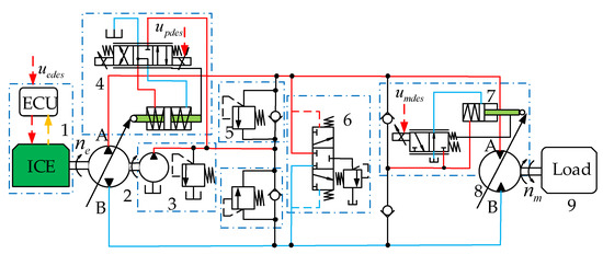
Figure 1.
Schematic structure of the HSDP. 1. Internal combustion engine (ICE). 2. Pump. 3. Charging system. 4. Pump displacement control unit (PDCU). 5. Safety valves. 6. Flushing valves. 7. Motor displacement control unit (MDCU). 8. Motor. 9. Load.
The engine (1) directly rotates the pump (2), with the speed being constantly adjusted by the engine controller (ECU). The pump displacement control unit (PDCU) (4) controls the displacement of the pump (2) and the direction of its oil outflow, and the pump (2) outputs oil flow to pipe A or pipe B according to the speed of the engine (1) and the displacement of the PDCU. The motor (8) drives the load (9) in a certain direction under the action of the pressurized oil from the pump (2), with the displacement being regulated by the motor displacement control unit (MDCU) (7). The charging system (3) maintains the low-pressure side of the closed circuit at a certain pressure through oil replenishment to compensate for the loss of the pump (2) and the motor (8). Combined with the charging system (3), the flushing systems (6) exchange the hot oil from the pipe with cooler oil to achieve heat dissipation. The safety system (5) is designed to prevent high system pressure and execute oil replenishment of the low-pressure side of the closed circuit. The control system can achieve stepless adjustment of the output speed of the motor (8) through the three control freedoms of the ICE, PDCU, and MDCU, resulting in two redundant control freedoms.
2.2. Variable Displacement Pump
The outflow of the pump is calculated as shown below:
where is the displacement ratio of the pump (for the ease of analysis, only a single direction adjustment of the pump is considered, i.e., ), is the pump’s maximum displacement, is the pump’s rotary speed, and is pump volume efficiency.
The electro-proportional control method is used for the PDCU, and its dynamics can be described by a reduced first-order model, as shown in Equation (2):
where is the time constant, is the control gain, and is the pump control signal.
In most practical applications, the actual value of is not available due to a lack of displacement sensors; however, its estimated value in its discrete form can be obtained based on Equation (2), as shown in Equation (3):
where is the sample time of the system .
The pump torque is calculated as shown below:
where is the pump’s mechanical efficiency, while is the pressure difference, which can be described as follows: .
2.3. Variable Displacement Motor
For simplification, oil compression is ignored, and according to the flow continuity principle, the motor output speed is expressed as follows:
where is the motor displacement ratio, is the motor’s maximum displacement, and is the motor’s volumetric efficiency.
The reduced first-order model is also used to describe the dynamics of the MDCU.
where is the time constant, is the control gain, and is the control signal.
Similarly, according to Equation (6), the estimated value of is calculated in discrete form:
The motor output torque is calculated as shown below:
where is the motor’s mechanical efficiency.
2.4. ICE Module
As shown in Figure 1, as the engine control unit (ECU) conducts closed-loop control of engine speed, the engine speed can be adjusted constantly by only changing the command. Ignoring the influence of the control error and engine droop, the speed control characteristic of the engine can be expressed as follows:
where is the engine speed, is the time constant, is the engine control signal, and is the control gain.
As the pump shaft is connected directly to the engine, the engine output torque is expressed as follows:
where is the equivalent moment inertia of the engine, and is the torque required for other systems (cooling, steering, charging, etc.).
3. The Adaptive Controller (ADC)
Figure 2 shows the schematic structure of the adaptive controller (ADC). The ADC is composed of an engine speed set module (ESSM), an efficiency estimation module (EEM), a displacement control module (PMDC), and an adaptive control module (ADCM). The ADC receives more than just the motor reference input from the handle: it also receives system feedback signals, such as the pressure signals , the engine speed signal , and the motor speed signal . The ESSM calculates the required power of the powertrain based on , , and and determines the desired speed control signal according to the required power. The EEM provides the estimated system efficiency in real time based on the pump/motor loss models and the system feedback signals. The PMDC sets the pump and motor displacement control signals based on and . The ADCM limits the control signals of the pump and the motor based on the preset pressure difference and the engine maximum torque to prevent engine overload stall and high system pressure.
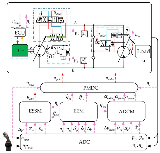
Figure 2.
Schematic of the adaptive controller (ADC).
Through the cooperative work of the four modules, automatic adaptability to varying loads can be attained along with efficient speed control.
3.1. Efficiency Estimation Module (EEM)
The volumetric efficiency and mechanical efficiency of the pump or motor shows a nonlinear relationship with system pressure, speed, and the displacement ratio [27,28]. In order to improve the accuracy of speed control and power estimation while ensuring the implementation of the system, we conducted real-time online estimation of the efficiencies of the system based on the system feedback signals and the pump/motor loss model. High-fidelity loss models of one specific variable pump and variable motor were established through the response surface method based on the Design-Expert-v8.0 software. The specific application of this software is described in [29]. The loss models of the tested variable pump and motor can be described using the polynomial equations shown in Equations (11)–(16).
The volumetric loss of the variable pump is expressed as follows:
Then, the volumetric efficiency of the variable pump can be estimated in the following manner:
The mechanical loss of the variable pump can be expressed as follows:
The mechanical efficiency of the variable pump can be estimated in the following manner:
Similarly, the volumetric loss of the variable motor can be described as follows:
Then, the volumetric efficiency of the variable motor can be calculated as follows:
The mechanical loss of the variable motor can be expressed as follows:
The mechanical efficiency of the variable motor can be determined as follows:
The estimated overall efficiency of the hydrostatic system is calculated as follows:
The scaling law can be applied to the loss models of a pump and motor of the same type but different sizes [30]. Then, the scaling factor is introduced to appropriately scale the speed, flow, displacement, and torque of the pump and the motor to extend them to the application range of the established loss models. The scaling law can be described using Equation (20) through to Equation (23).
where are the rated displacement of the applied and tested pump or motor, respectively.
3.2. Engine Speed Set Module (ESSM)
Brake-specific fuel consumption (BSFC) is a measuring index of engine fuel economy; the lower the value, the better the fuel economy. Figure 3 shows the universal characteristic curve of a certain engine; it can be seen that the BSFC is different under different speeds and different loads, and its minimum value is reached when the load torque is close to the maximum torque at the current speed. Therefore, for each engine speed , there is an engine power level with minimum BSFC. Then, the engine optimal operating curve (OOL) can be created by connecting these points , as shown in Figure 3. Using the polynomial fitting method, the relationship between and is expressed as follows:
where are the fitting coefficients.
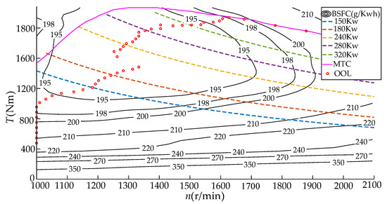
Figure 3.
Universal characteristic map of the engine.
Taking the minimum speed requirement of the pump and other systems into consideration while avoiding the frequent speed adjustment of the engine, we designed a sub-optimal engine operating curve (Sub-OOL) based on segmented speed control, as shown in Figure 4.
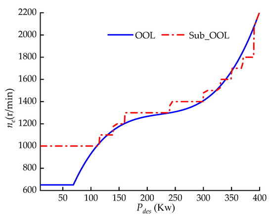
Figure 4.
Segmented speed control of the engine.
Using the motor reference speed , the system feedback differential pressure and the estimated and , the real time desired engine power can be calculated as follows:
Based on the desired engine power , the desired engine speed can be determined according to the Sub-OOL curve (shown in Figure 4). Then, referring to Equation (9), the desired engine speed control signal can be expressed as follows:
3.3. Displacement Control Module (PMDC)
Previous studies have systematically analyzed the efficiency of closed hydrostatic systems and pointed out that in most working areas, the efficiency of a hydrostatic system increases with the increase in the displacement of the pump and the motor [31,32,33]. Accordingly, in this paper, we propose a displacement control strategy based on sequential logic control. This strategy is as follows: when the desired pump displacement ratio does not reach its maximum , then maintain the desired motor displacement ratio at its maximum value 1 and regulate the motor speed by adjusting based on ; furthermore, after reaches up to , maintain at and regulate the motor speed through adjusting according to .
According to the flow continuity equation obtained with Equations (1) and (5), the sequential control logic of the PMDC can be described by Equation (27):
Herein, are the upper limit of the pump displacement ratio and the lower limit of the motor displacement ratio, respectively, which are to be determined via the ADCM in the next section. To be specific, Figure 5 shows the control law of and under different and .
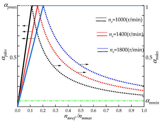
Figure 5.
Control law of and .
According to Equation (3), the desired pump control signal is calculated as follows:
Similarly, according to Equation (7), the desired motor control signal is calculated as follows:
3.4. Adaptive Control Module (ADCM)
Figure 3 shows the max torque curve (MTC) of the engine, and it can be seen that there is a maximum output torque at each engine speed , beyond which the load will lead to engine speed droop or engine stall. The polynomial fitting method was also adopted to establish the relationship between and , as expressed in Equation (30):
Here, are the fitting coefficients.
Combining Equation (4) with Equation (10) and ignoring the torque demand of other systems, the torque relationship between the engine and the pump under steady-state conditions can be approximately expressed as follows:
In order to ensure the engine abilities of overload resistance and acceleration while taking into account the actual torque needs of other systems (cooling, charging, steering, etc.), 80% of the maximum torque was selected as the available torque for the HSDP system.
The ADCM is capable of more than just limiting the maximum engine output torque by limiting of the pump to prevent engine speed droop or engine stall; it can also avoid high system pressure by limiting the minimum displacement ratio of the motor, thus improving the automatic adaptability of the HSDP system to varying loads.
To maintain the engine torque so it does not exceed its available under a certain speed, based on Equations (30) and (31), the real-time of the pump can be calculated by Equation (32). Figure 6 shows the variation of with pressure difference and engine speed .
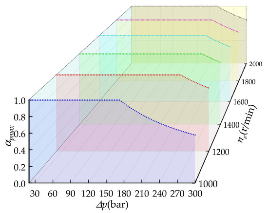
Figure 6.
Variation in under different values of and .
The predefined maximum pressure difference and the control gain are introduced to limit the system maximum pressure according to Equation (8), and the real-time of the motor can be calculated by Equation (33). Figure 7 shows the variation of with pressure difference and the desired motor displacement ratio :
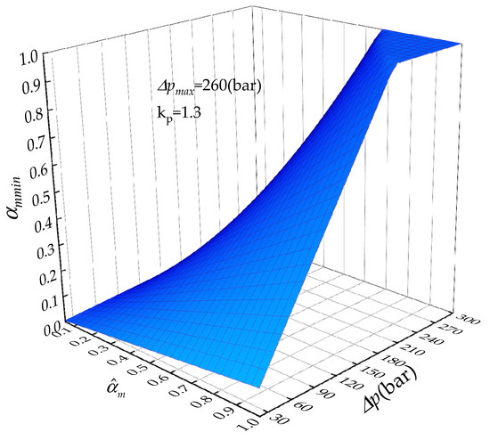
Figure 7.
Variation in under different values of and .
4. Experimental Investigation
Experimental field tests based on one THY900 heavy transport vehicle from a company were carried out to verify the effectiveness of the proposed controller. The vehicle used a closed hydrostatic powertrain (HSDP) as its travel drive system. A schematic of the HSDP system of the vehicle is shown in Figure 8a, and Figure 8c shows a photograph of the test vehicle. The HSDP system employs a driving mode in which parallel multipumps drive parallel mutimotors and the control system employs a distributed integrated control structure based on CANbus. Moreover, Dewesoft software was used to collect and record the system control and status signals. Table 1 shows basic information on the heavy transportation vehicle, and Table 2 shows the basic parameters of the main components of the vehicle’s HSDP system.
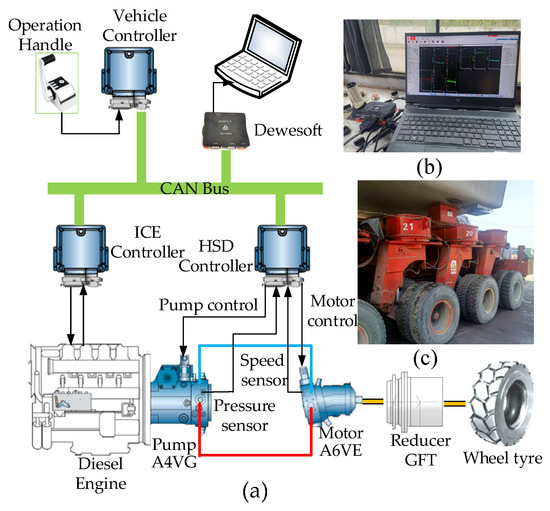
Figure 8.
(a) Sketched structure of the HSDP system. (b) Scene depicting the testing of the vehicle. (c) Photograph of the test vehicle.

Table 1.
Basic information on THY900 vehicle.
Table 2.
Basic parameters of the HSDP components.
4.1. Testing Procedure
In this study, we tested and analyzed the speed control characteristics and adaptability to varying loads of the ADC under different travel conditions, such as no load or heavy load, driving on slopes, and driving at different travel speeds. In terms of energy saving, comparison tests between a rule-based controller (RBC) and ADC were conducted to verify the efficacy in energy saving of the ADC. A scene depicting the vehicle test is shown in Figure 8b.
Rule-Based Controller (RBC)
The control rules adopted by the RBC are widely used in commercial hydrostatic drive systems [25,34,35], in which the set speed of the engine is proportional to the reference input from the operators and the displacement of the variable pump and the variable motor are adjusted according to the engine speed and reference input. Combined with the displacement control logic of the PMDC, a rule-based controller for the vehicle was developed, and the control logic of the RBC is shown in Figure 9.
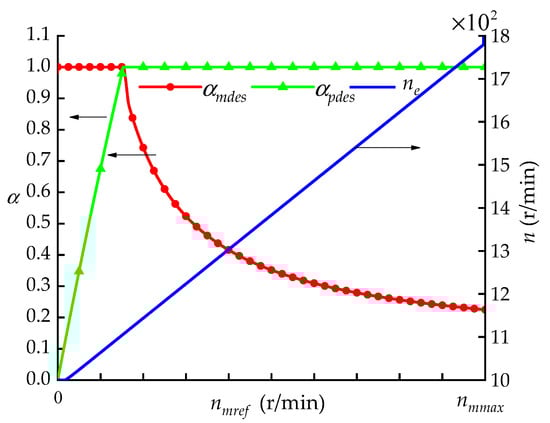
Figure 9.
The commands of the rule-based controller (RBC).
The principle of the RBC is that after the RBC receives the travel commands from the operator, the engine speed increases from idle to 1000 r/min and then increases in proportion with the increase in the reference input . When the reference input reaches its maximum (Table 1), the engine speed reaches its maximum of 1800 r/min. The control signals for the variable pump and the variable motor are determined according to the control law of PMDC.
4.2. Analysis of the Experimental Results
The performance of the ADC was analyzed comprehensively in terms of speed control, adaptability, and energy saving.
4.2.1. Characteristic of Speed Control
For spatial reasons, this paper only shows the system running states and control information in the process of the vehicle accelerating from zero to its allowable maximum speed under flat slope conditions with a heavy load and an empty load. Figure 10a shows the variation in the motor speed and the reference input . The motor speed can closely track the variation in and maintain good tracking accuracy. Figure 10b shows the variation process of the parameters, , , and , and it can be seen that the three variables change cooperatively in accordance with the rules set by the ADC, thus ensuring the tracking accuracy of to .
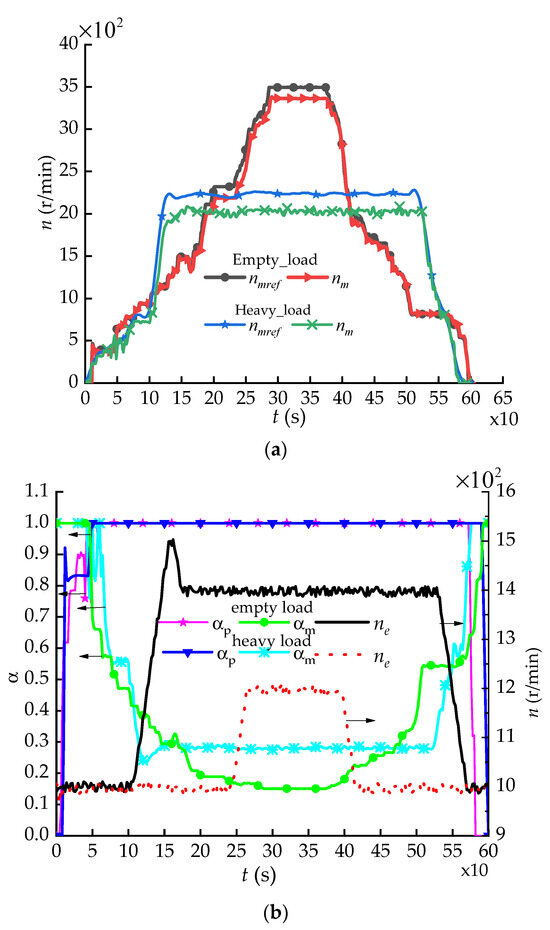
Figure 10.
Operating parameter variation of the vehicle. (a) Variation in motor speeds. (b) Variation in , , and .
A statistical analysis was conducted to analyze the speed control accuracy of the ADC. The speed control error was defined as , and the average speed error ratio was defined as , where is the average of , and is the average of . The statistical results are shown in Table 3.
Table 3.
Statistical results regarding speed control.
As can be seen in Table 3, the average speed error ratio of the vehicle was 3.3% under empty load conditions and 9.5% under heavy load conditions. Better speed control accuracy was achieved for the vehicle, verifying the efficacy of the ADC in speed control.
Nevertheless, there were still certain control errors for the vehicle speed under both conditions, and the errors under heavy load conditions were greater than those under empty load conditions. This phenomenon can be attributed to the reduced accuracy of the loss model of the pump and the motor caused by oil compression in the pipeline and the wear of the pumps and motors, problems that need to be addressed in future research.
4.2.2. Adaptive Characteristic
In view of the actual testing conditions for the vehicle, testing conditions of a heavy load and 2.5% slope were chosen to test the adaptability of the HSDP system. Moreover, to make the results more intuitive, the system reference input was always kept at its maximum value while the vehicle was climbing the slope. Figure 11a shows the variation in , , and , and Figure 11b shows the variation in , and during the process of vehicle climbing.
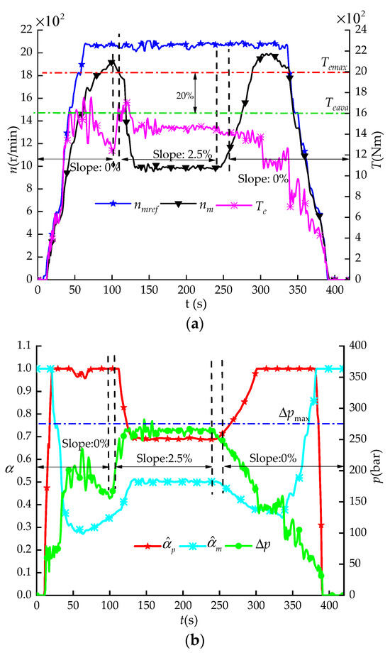
Figure 11.
Variation processes of adaptive control. (a) Variation in motor speeds. (b) Variation process of .
It can be seen that when , the vehicle ascended 2.5% the slope, and the and began to increase. The ADC prevented the rising engine output torque from exceeding its available torque by reducing the pump displacement ratio . Meanwhile, the ADC also kept the pressure difference from rising above the predefined pressure difference by increasing the motor displacement ratio . Eventually, the adaptive controller (ADC) reduced the motor speed to adapt to the increasing loads, and was maintained around . When , the loads of the motor decreased as the slope decreased to zero. Then, the ADC increased the and decreased the automatically to align the motor speed with the reference input again. The ADC is capable of adjusting the displacement of the pumps and motors automatically according to the vehicle loads to prevent engine stall and high system pressure, verifying the effectiveness of the ADC in terms of adaptability.
4.2.3. Energy-Saving Characteristics
The fuel consumption rate , i.e., the amount of fuel consumed per unit of traveling distance , was chosen as the measuring unit to evaluate the fuel economy of the engine to reduce the impact of the difference in instantaneous fuel consumption and speed control errors on the evaluation results. Comparison tests between the ADC and RBC were carried out under different conditions. However, for ease of analysis, only the statistical results obtained for a flat slope (0%) are given, which are shown in Table 4.
Table 4.
The comparative results of RBC and ADC.
As shown in Table 4, the fuel consumption rate of the ADC was lower than that of the RBC under both heavy load and empty load conditions. Specifically, the energy-saving ratio was at least 11.4% and up to 25.8% under empty load conditions and at least 2.8% and up to 9% under heavy load conditions. The decreasing fuel consumption rate is proof of the effectiveness of the ADC in energy saving.
Additionally, the results of the comparison tests under other conditions are presented in the form of a scatter plot of the engine operating points in Figure 12.
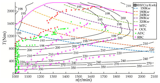
Figure 12.
Scatter plot of engine operating points.
It can be seen from Figure 12 that the engine operating points under the control of the rule-based controller (RBC) are more dispersed than those under the adaptive controller (ADC), which shows that the engine operating points of the RBC are easily affected by changes in the vehicle power. With the increase in power, the engine operating points become closer to the optimal operating line (OOL). However, the engine operating points of the ADC are more concentrated around the OOL than those of RBC, especially when the vehicle power is below 150 kw. When the power is above 150 kw, they become further away from the OOL as power increases but still remain closer to the OOL than those of the RBC, which indicates that the engine operating points of the ADC are less influenced by changes in the vehicle power. The optimal operating line (OOL) of the engine is drawn based on the principle of the minimum BSFC under certain operating points of the engine, with greater energy savings at points closer to the OOL. Therefore, the ADC performed better in terms of energy saving than the RBC during most of the driving conditions.
5. Discussions and Future Work
Although the accuracy of the speed control satisfies the requirements of heavy transportation vehicles, it is still not a satisfactory result. The accuracy of the speed control of the proposed ADC is easily affected by the load conditions of the vehicle, which can be attributed to the semiclosed loop speed control method based on the established loss models. The loss models of the pump and the motor ignore the oil compression and the wear of the pumps and motors, which decreases the accuracy of the loss models to some extent. Therefore, in future research, a full closed-loop speed control strategy will be investigated and integrated into the control system to compensate for the modeling error of the loss models, thus further improving the speed control accuracy. Moreover, while the energy-saving effect of the ADC was validated using the reported tests, it cannot ensure the optimal performance in all driving situations, especially in driving conditions involving rapidly changing loads. Additionally, the BSFC curves of the engine were only tested under steady-state conditions, which will cause increased fuel consumption in dynamic situations. In the future, model-based control strategies, which consider the dynamic effect of the HSDP system, will be investigated to provide better overall fuel economy.
6. Conclusions
Focusing on a closed hydrostatic powertrain (HSDP) composed of an engine, a variable pump, and a variable motor, this paper proposes an energy-efficient adaptive speed-regulating controller (ADC) based on power following. As well as ensuring accurate speed control through online system efficiency estimation based on the pump/motor loss model and the system feedback signal, this controller can also seek the optimal efficiency control of the engine and the hydrostatic system through the two redundant control freedoms of the HSDP system. Meanwhile, the controller can prevent engine overload stall and high system pressure by limiting the displacement of the pumps and motors based on the loads of the system in real time to improve the automatic adaptability of the system to varying loads. Experimental field tests based on a heavy transportation vehicle were carried out to verify the efficacy of the ADC in terms of speed control accuracy and adaptability. Moreover, tests comparing a rule-based controller (RBC) and the ADC were also conducted to validate the energy-saving effect of the ADC. The field experimental results indicate the following:
- The ADC can allow the motor speed to accurately track changes in the reference and maintain an accuracy with an average error of 3.3% under empty load conditions and 9.5% under heavy load conditions.
- The ADC reduces motor speed automatically through the displacement adjustment of the pumps and the motors to allow the HSDP system to adapt to rising loads, thus preventing engine overload stall and high system pressure.
- Compared to the RBC, the energy-saving ratio of the ADC is at least 11.4% and up to 25.8% under empty load conditions and at least 2.8% and up to 9% under heavy load conditions, showing the significant energy-saving effect of the ADC.
Author Contributions
Conceptualization, H.W. and R.L.; methodology, H.W.; software, H.W.; validation, H.W., Z.A. and Y.Z.; formal analysis, H.W.; investigation, H.W.; resources, H.W. and Z.A.; data curation, H.W. and R.L.; writing—original draft preparation, H.W.; writing—review and editing, H.W. and Y.Z.; visualization, Y.Z.; project administration, Y.Z. All authors have read and agreed to the published version of the manuscript.
Funding
This research is supported by the Key Scientific and Technological Project of Henan Province (No.232102220044), the Science and Technology Research Project of the Science and Technology Department from Henan Province (No. 212102210225), and the 2023 Science and Technology Development Plan Project of China Railway 11th Bureau Group Co., LTD (No. 23-AII-08).
Data Availability Statement
All data used in this manuscript can be made available upon request.
Acknowledgments
The test vehicle and test sites are provided by the 3rd Engineering Co., Ltd., China Railway 11th Bureau Group.
Conflicts of Interest
Zhangshun An was employed by China Railway 11 Bureau Group. The remaining authors declare that the research was conducted in the absence of any commercial or financial relationships that could be constructed as a potential conflict of interest.
References
- Yang, X.; Gong, G.; Yang, H.; Jia, L.; Zhou, J. An investigation in performance of a variable speed displacement pump-controlled motor system. IEEE/ASME Trans. Mechatron. 2017, 22, 647–656. [Google Scholar] [CrossRef]
- Sakaino, S.; Sakuma, T.; Tsuji, T. A control strategy for electro-hydrostatic actuator considering static friction, resonance, and oil Leakage. IEEE J. Ind. Appl. 2019, 8, 279–286. [Google Scholar] [CrossRef]
- Shi, H.; Yang, H.; Gong, G.; Liu, H.; Hou, D. Energy saving of cutterhead hydraulic drive system of shield tunneling machine. Autom. Constr. 2014, 37, 11–21. [Google Scholar] [CrossRef]
- Zhang, Q.; Wang, F.; Cheng, M.; Xu, B. Energy efficiency improvement of battery powered wheel loader with an electric-hydrostatic hybrid powertrain. Proc. Inst. Mech. Eng. Part D J. Automob. Eng. 2022, 237, 75–88. [Google Scholar] [CrossRef]
- Li, Y.; He, L. Counterbalancing speed control for hydrostatic drive heavy vehicle under long down-slope. IEEE/ASME Trans. Mechatron. 2015, 20, 1533–1542. [Google Scholar] [CrossRef]
- Wang, F.; Wu, Z.; Xu, B.; Fiebig, W. A mode-driven control strategy to reduce electric drive peak power of hybrid wheel loader propulsion system. IEEE Trans. Veh. Technol. 2023, 72, 5948–5961. [Google Scholar] [CrossRef]
- Bender, F.; Kaszynski, M.; Sawodny, O. Drive cycle prediction and energy management optimization for hybrid hydraulic vehicles. IEEE Trans. Veh. Technol. 2013, 62, 3581–3592. [Google Scholar] [CrossRef]
- Hippalgaonkar, R.; Ivantysynova, M. Optimal power management of hydraulic hybrid mobile machines—Part I: Theoretical studies, modeling and simulation. J. Dyn. Syst. Meas. Control 2016, 138, 100201–100223. [Google Scholar] [CrossRef]
- Kim, H.; Yoo, S.; Cho, S.; Yi, K. Hybrid control algorithm for fuel consumption of a compound hybrid excavator. Autom. Constr. 2016, 68, 1–10. [Google Scholar] [CrossRef]
- Kwon, H.; Ivantysynova, M. Experimental and theoretical studies on energy characteristics of hydraulic hybrids for thermal management. Energy 2021, 223, 120033. [Google Scholar] [CrossRef]
- Ge, L.; Quan, L.; Zhang, X.; Dong, Z.; Yang, J. Power matching and energy efficiency improvement of hydraulic excavator driven with Speed and displacement variable power source. Chin. J. Mech. Eng. 2019, 32, 100. [Google Scholar] [CrossRef]
- Sun, H.; Yang, L.F.; Jing, J.Q. Hydraulic/electric synergy system (HESS) design for heavy hybrid vehicles. Energy 2010, 35, 5328–5335. [Google Scholar]
- Ge, L.; Quan, L.; Zhang, X.; Zhao, B.; Yang, J. Efficiency improvement and evaluation of electric hydraulic excavator with speed and displacement variable pump. Energy Convers. Manag. 2017, 150, 62–71. [Google Scholar] [CrossRef]
- Yan, Z.; Ge, L.; Quan, L. Energy-efficient electro-hydraulic power source driven by variable-speed motor. Energies 2022, 15, 4804. [Google Scholar] [CrossRef]
- Wang, F.; Hong, J.Y.; Ding, R.Q.; Xu, B.; Fiebig, W.J. A torque conversion solution to the powertrain of mobile machine and its control strategy. IEEE Trans. Veh. Technol. 2022, 71, 10361–10373. [Google Scholar] [CrossRef]
- He, X.; Liu, H.; He, S.; Hu, B.; Xiao, G. Research on the energy efficiency of energy regeneration systems for a battery-powered hydrostatic vehicle. Energy 2019, 178, 400–418. [Google Scholar] [CrossRef]
- Castaings, A.; Lhomme, W.; Trigui, R.; Bouscayrol, A. Comparison of energy management strategies of a battery/supercapacitors system for electric vehicle under real-time constraints. Appl. Energy 2016, 163, 190–200. [Google Scholar] [CrossRef]
- Froehlich, C.; Kemmetmuller, W.; Kugi, A. Model predictive control of servo-pump driven injection molding machines. IEEE Trans. Control Syst. Technol. 2020, 28, 1665–1680. [Google Scholar] [CrossRef]
- Deppen, T.O.; Alleyne, A.G.; Meyer, J.J.; Stelson, K.A. Comparative study of energy management strategies for hydraulic hybrids. J. Dyn. Syst. Meas. Control 2015, 137, 041002. [Google Scholar] [CrossRef]
- Zhang, Q.; Wang, F.; Xu, B.; Sun, Z. Online optimization of Pontryagin’s minimum principle for a series hydraulic hybrid wheel loader. Proc. Inst. Mech. Eng. Part D J. Automob. Eng. 2021, 236, 1487–1499. [Google Scholar] [CrossRef]
- Jung, D.; Cho, S.W.; Park, S.J.; Min, K.D. Application of a modified thermostatic control strategy to parallel mild HEV for improving fuel economy in urban driving conditions. Int. J. Automot. Technol. 2016, 17, 339–346. [Google Scholar] [CrossRef]
- Wen, Q.Y.; Wang, F.; Xu, B.; Sun, Z. Improving the fuel efficiency of compact wheel loader with a series hydraulic hybrid powertrain. IEEE Trans. Veh. Technol. 2020, 69, 10700–10709. [Google Scholar] [CrossRef]
- Do, H.T.; Park, H.G.; Ahn, K.K. Application of an adaptive fuzzy sliding mode controller in velocity control of a secondary controlled hydrostatic transmission system. Mechatronics 2014, 24, 1157–1165. [Google Scholar] [CrossRef]
- Backas, J.; Ghabcheloo, R.; Tkkanen, S.; Huhtala, K. Fuel optimal controller for hydrostatic drives and real-world experiments on a wheel loader. Int. J. Fluid Power 2016, 17, 187–201. [Google Scholar] [CrossRef]
- Zhao, J.Y.; Wang, Z.Y.; Qin, Y.M.; Wang, J.X. Research on the hydraulic driving system and engine power match in TLC900 transporting grider vehicle. Chin. J. Mech. Eng. 2007, 18, 878–881. [Google Scholar]
- Ye, H.; Ni, X.; Chen, H.; Li, D.; Pan, W. Constant speed control of hydraulic travel system based on neural network algorithm. Processes 2022, 10, 944. [Google Scholar] [CrossRef]
- Zeng, X.; Li Ly Song, D.; Li, L.; Li, G. Model predictive control based on time-varying efficiency for hydraulic hub-motor driving vehicle. Proc. Inst. Mech. Eng. Part D J. Automob. Eng. 2021, 235, 2949–2963. [Google Scholar] [CrossRef]
- Xu, B. Characteristics of volumetric losses and efficiency of axial piston pump with respect to displacement conditions. J. Zhejiang Univ. Sci. A 2016, 17, 186–201. [Google Scholar] [CrossRef]
- Tan, Y.; Yu, X.; Wang, X.; Lv, Q.; Shi, M. Interaction analysis and multi-response optimization of transformer winding design parameters. Int. Commun. Heat Mass Transf. 2022, 137, 106233. [Google Scholar] [CrossRef]
- Keller, N.; Ivantysynova, M. A new approach to sizing low pressure systems. In Proceedings of the ASME/BATH 2017 Symposium on Fluid Power & Motion Control, Sarasota, FL, USA, 16–19 October 2017. [Google Scholar]
- Vardhan, A.; Dasgupta, K. Mapping the efficiency of the hydrostatic drive for the rotary head of drill machine using high-speed low-torque hydraulic motors. Arab. J. Sci. Eng. 2018, 43, 4703–4712. [Google Scholar] [CrossRef]
- Manring, N.D. Mapping the efficiency for a hydrostatic transmission. J. Dyn. Syst. Meas. Control 2016, 138, 031004. [Google Scholar] [CrossRef]
- Pandey, A.K.; Vardhan, A.; Dasgupta, K. Theoretical and experimental studies of the steady-state performance of a primary and secondary-controlled closed-circuit hydrostatic drive. Proc. Inst. Mech. Eng. Part E J. Process Mech. Eng. 2019, 233, 1024–1035. [Google Scholar] [CrossRef]
- Bosch Rexroth, A.G. Easy Machine Operation with Rexroth Automotive Drive and Anti-Stall Control; Bosch Group: Elchingen, Germany, 2003. [Google Scholar]
- Eaton Corporation. ETAC: Electronic Transmission Automotive Control User’s Manual; Eaton Corporation: Eden Prairie, MN, USA, 2007. [Google Scholar]
Disclaimer/Publisher’s Note: The statements, opinions and data contained in all publications are solely those of the individual author(s) and contributor(s) and not of MDPI and/or the editor(s). MDPI and/or the editor(s) disclaim responsibility for any injury to people or property resulting from any ideas, methods, instructions or products referred to in the content. |
© 2023 by the authors. Licensee MDPI, Basel, Switzerland. This article is an open access article distributed under the terms and conditions of the Creative Commons Attribution (CC BY) license (https://creativecommons.org/licenses/by/4.0/).