1. Introduction
Saline soil is defined as soil in which the soluble salt content is higher than 0.3%, which occurs widely around the world, covering an area of more than 1 billion hectares. The distribution of saline soils in China spans a vast geographical range, encompassing inland plains, Bohai Bay, northern desert regions, and humid tropical areas in the south [
1,
2]. Saline soils exhibit distinct characteristics stemming from the presence of soluble salt ions, specifically Cl
− and SO
42−. These ions exert significant influence on the physicochemical properties of saline soils. Variations in water content, temperature, and humidity prompt the dissolution and crystallization of soluble salt ions, perpetuating a cyclical process that aligns with seasonal changes. The repetitive precipitation of salt crystals engenders detrimental effects on soil structure, leading to recurring instances of swelling and compaction. Moreover, Cl
− and SO
42− manifest corrosive properties towards metals and concrete, thereby posing potential threats to infrastructure integrity [
3,
4,
5]. The collapsibility, salt expansion, and corrosive nature of saline soils not only entail inherent risks for constructions but also give rise to serious economic loss. Furthermore, the distinctive characteristics of saline soil contribute to a decline in fertility and nutrient deficiencies, impacting soil biology adversely and impeding plant growth [
6]. Consequently, most crops are unsuitable for cultivation in saline soils, resulting in crop yield decreases. The terrible engineering properties of saline soil make it necessary to be improved before it can be used in construction [
7].
Inorganic soil stabilizers are widely utilized in practical applications, with cement and lime and coal fly ash being prevalent choices. Nevertheless, these agents exhibit inherent limitations and deficiencies [
8,
9]. The solidified soil treated with cement often yields high early strength, but it is accompanied by a high collapsibility coefficient and a limited strength development during the later stages. Notably, Zhang [
10] used cement for the treatment of saline soils and achieved an unconfined compressive strength of 1.03 MPa at 7 d using a 4% cement content. However, the collapsibility coefficient of the solidified soil reached 0.6% at 600 kPa, suggesting a suboptimal enhancement effect. Conversely, the soil treated with lime and coal fly ash shows promising potential for strength development during the later stages while exhibiting low early strength. Dang [
11] used a combination of 6% lime and 18% coal fly ash in the curing agent, resulting in an unconfined compressive strength of 0.75 MPa at 7 d, which met the requirements reluctantly and posed limitations in practical applications. It is noteworthy that the cement production entails calcination and the decomposition of limestone, resulting in substantial carbon dioxide emissions. In 2022, total carbon dioxide emissions in China surpassed 10 billion tons, and the cement industry accounted for more than 14% of overall emissions. Furthermore, the lime industry contributes nearly 3% of the carbon dioxide emissions and is recognized as a highly polluting industry [
12,
13]. In response to China’s initiatives to reduce carbon dioxide emissions, restrictions have been implemented on cement and lime production. Consequently, continuous reliance on cement and lime for the construction industry would inevitably result in increased costs and limited application. Hence, there is an urgent imperative to explore environmentally friendly alternatives for soil stabilizers.
Numerous scholars have extensively researched the utilization of cementitious materials based on solid wastes to stabilize soils. Cui [
14] investigated into the fundamental aspects of the synergistic hydration reaction between steel slag and GBF slag. The investigation unveiled the excitation effect of FGD gypsum on the steel slag and GBF slag, with a collective influence of diverse hydration products on the system’s strength enhancement. Wang [
15] used GBF slag, coal fly ash, FGD gypsum, and lime to effectively solidify saline soil. The focus was directed towards comprehending the migration and transformation processes of each constituent in the raw materials. The study identified the essential role played by electrovalence imbalance in achieving NaCl curing. Xu [
16] adopted a tetrameric system, comprising caustic sludge, steel slag, GBF slag, and FGD gypsum, as the cementitious material. The investigation shed light on the formation process of hydration products, including ettringite, calcium silicate (alumina) hydrate, and Friedel’s salt. The study also revealed the curing mechanism of the system. The related research shows that CaCO
3 can optimize the cementitious system’s filling situation and provide growth nodules for C-S-H gel [
17]. The ion exchange of Cl
− was observed to lead to the formation of Friedel’s salt [
18]. An [
19] used a combination of carbide slag and caustic sludge as an activator for the cementitious material, resulting in improved early strength of the specimens. Wen [
20] used coal fly ash, phosphogypsum, and carbide slag as curing agents for the solidification of silty soil. A regression model was developed to assess the compressive strength and water stability at different stages. According to the model, a strength of 4.136 MPa at 7 d was achieved for silty soil when the coal fly ash and phosphorgypsum contents were 5.1%, and the carbide slag content was 9.8%. Zeng [
21] utilized lime, GBF slag, and coal fly ash as curing agents for the treatment of construction waste. The water stability and microstructure of the solidified soil were thoroughly analyzed across various ratios. The resulting unconfined compressive strength of the solidified soil at 7 d reached 2.35 MPa, with a lime content of 10%, a GBF slag content of 81%, a coal fly ash content of 9%, and a curing agent content of 15%.
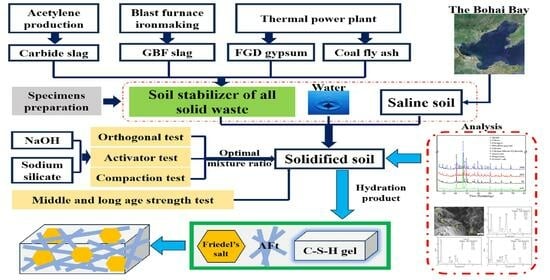
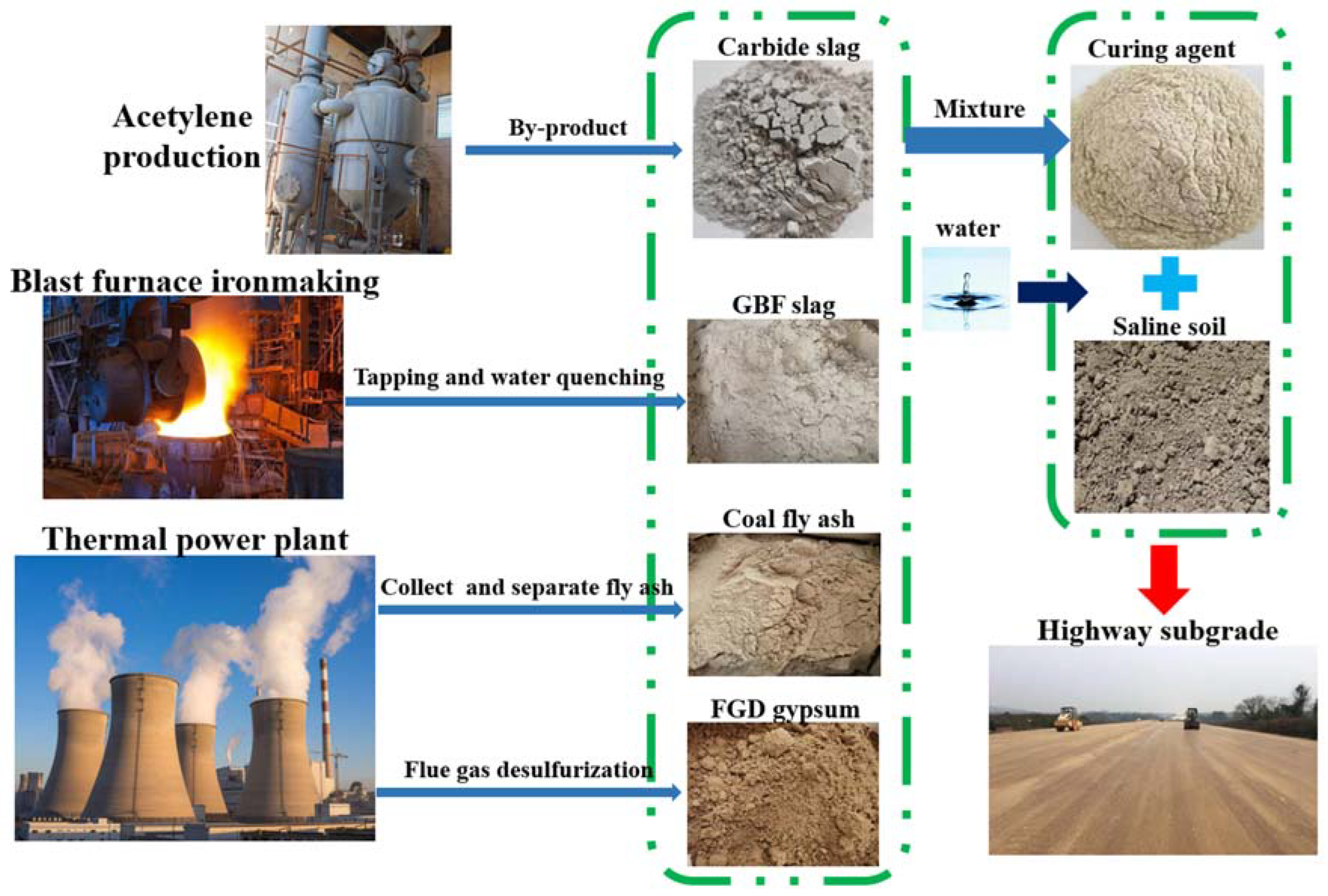
The industrial solid wastes have shown promising potential for the solidification of saline soil. In the study, carbide slag, GBF slag, coal fly ash, and FGD gypsum were adopted as primary constituents to produce soil stabilizers. Sodium silicate and NaOH were tested as alkaline activators. The excitation effect was evaluated by the unconfined compressive strength of specimens. Additionally, the investigation was aimed at optimizing the proportion of the raw materials to fabricate soil stabilizers and revealing the related hydration mechanism. The process schematic diagram is shown in
Figure 1.
3. Results
3.1. Orthogonal Test Results and Analysis
The orthogonal test results and the range analysis are displayed in
Table 6. It is shown in
Table 6 that the values demonstrate the following hierarchy of influence: R
A (0.43) > R
B (0.34) > R
C (0.25). As a result, the impact of each factor on the unconfined compressive strength of the solidified soil at 7 d is decreased as follows: A (carbide slag content) > B (GBF slag content) > C (FGD gypsum content).
The unconfined compressive strength of the solidified soil at 7 d initially rises and then declines with increasing carbide slag content. Optimal strength is achieved at a carbide slag content of 30%, indicating that a moderate amount of carbide slag enhances the hydration reaction and strengthens the solidified soil. However, excessive carbide slag content leads to a decrease. Similarly, the unconfined compressive strength of the solidified soil at 7 d increases with higher GBF slag content, reaching its peak at 25%. This can be attributed to the abundant presence of reactive silicon oxides or aluminum oxides in the GBF slag, which facilitates rapid hydration reactions. Under alkaline conditions, the hydration reaction of GBF slag occurs at a faster rate than the volcanic ash reaction of coal fly ash, thereby enhancing the early strength of the solidified soil. Conversely, variations in FGD gypsum content have minimal influence on the strength of the solidified soil.
The range analysis reveals that the optimal ratio of the curing agent is A2B3C2. This specific ratio consists of 30% carbide slag, 25% GBF slag, 35% coal fly ash, and 10% FGD gypsum, and it is referred as B-1 in this work. The verification experiment was conducted at this ratio; the unconfined compressive strength of the solidified soil at 7 d reached 1.07 MPa.
3.2. Compaction Characteristics and Strength with Various Contents of Curing Agents
The tests described above were conducted using a curing agent content of 20%, taking into account the maximum dry density and optimum moisture content of the plain soil. These parameters were selected to ensure the combined curing agent and saline soil to achieve the maximum dry density and optimum moisture content.
The compaction test was performed using the B-1 ratio in conjunction with curing agent contents ranging from 16% to 24%. Standard test blocks were prepared for assessment based on the maximum dry density and optimum moisture content of the solidified soil at different curing agent contents. The study investigated the relationship between the curing agent content and the unconfined compressive strength of the solidified soil at 7 d, and the findings are showed in
Figure 3. The compaction curves of the mixtures of curing agent and saline soil at different curing agent contents is shown in
Figure S2.
As shown in
Figure 3, the maximum dry density of the solidified soil decreased, while the optimum moisture content and the unconfined compressive strength at 7 d increased with an increase in curing agent content. It can be attributed to the large specific surface area and strong water absorption capacity of the raw materials of the curing agent. The higher curing agent content leads to the increase in the water requirement and the decrease in the dry density of the mixture of curing agent and saline soil. At a curing agent content of 24%, the maximum dry density of the solidified soil was 1.74 g/cm
3, the optimum moisture content was 18.35%, and the unconfined compressive strength at 7 d was 1.78 MPa. Comparing this result to a curing agent content of 16%, the maximum dry density decreased by 0.57%, while the optimum moisture content increased by 4.92% and the unconfined compressive strength at 7 d increased by 125.32%.
In the current road construction engineering in North China, the unconfined compressive strength of solidified coastal saline soil at 7 days should be above 1.0 MPa to ensure satisfactory road properties. Therefore, the curing agent content of 20% is selected as an appropriate dosage of the curing agent in this work.
When the curing agent content is 20%, the solidified soil attains a maximum dry density of 1.748 g/cm3 and an optimum moisture content of 17.95%. This specific combination is denoted as B-2 in the experimental setting. Consequently, the unconfined compressive strength of the solidified soil at 7 d reaches 1.13 MPa, exhibiting a 5.61% improvement compared to the B-1 experimental group.
3.3. Excitation Effect of Alkaline Activators
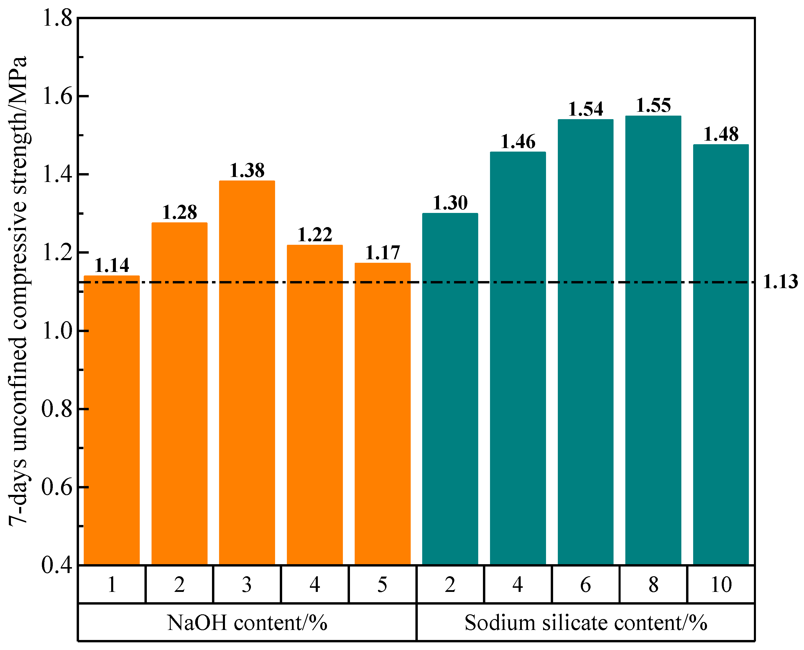
In this experiment, the excitation effect of two types of alkaline activators, sodium silicate and NaOH, were investigated at different contents, using the B-2 mixture ratio as the baseline. Due to the higher alkalinity of NaOH compared to sodium silicate, a reduced amount of sodium silicate is utilized in the experimental setup. Equal contents of the activators are used to replace the carbide slag. For example, the addition of 1% NaOH represents a substitution from 30% carbide slag to 1% NaOH and 29% carbide slag. The experiments are conducted by replacing equal proportions of carbide slag with NaOH contents of 1%, 2%, 3%, 4%, and 5%, as well as sodium silicate contents of 2%, 4%, 6%, 8%, and 10%. The outcomes of these experiments are showed in
Figure 4.
As shown in
Figure 4, replacing an equivalent quantity of carbide slag with NaOH or sodium silicate leads to an increased strength of the solidified soil. However, for either NaOH or sodium silicate, the strength of the solidified soil can decrease from the high content of alkaline activators. Relatively, the sodium silicate demonstrated the more favorable excitation effect compared to the NaOH.
When the solidified soil was treated with 1% NaOH, the unconfined compressive strength at 7 d reached 1.14 MPa, showing a relatively marginal improvement compared to the B-2 experimental group. The addition of 3% NaOH resulted in a significant increase in the unconfined compressive strength at 7 d reaching 1.38 MPa, representing a substantial enhancement of 22.12% compared to the B-2 experimental group. The notable impact was evident in this case. With the addition of 5% NaOH, the unconfined compressive strength at 7 d was 15.22% lower than the strength observed with 3% NaOH. These findings suggest that while NaOH demonstrates a certain excitation effect, excessive amounts can adversely affect the structural integrity of the system.
When 2%, 4%, and 6% contents of sodium silicate were introduced, the increases in the unconfined compressive strength at 7 d became more and more obvious, when compared to the B-2 experimental group. The addition of 8% sodium silicate did not significantly alter the strength in comparison to the 6% content. The addition of 10% sodium silicate led to a substantial improvement, with the unconfined compressive strength at 7 d reaching 1.48 MPa. However, the strength at this content experienced a slight decrease relative to the 6% and 8% contents. The findings suggest that sodium silicate exerts a favorable stimulating effect on the strength of the solidified soil, particularly at lower contents. Further increases in content beyond 6% do not yield significant effects on the structural strength.
Considering the growth enhancement rate of strength by increasing the sodium silicate content, subsequent tests will utilize a 4% content of sodium silicate. The resulting mixture, denoted as B-3, comprised of 4% sodium silicate, 26% carbide slag, 25% GBF slag, 35% coal fly ash, and 10% FGD gypsum. This particular mixture demonstrated a maximum dry density of 1.75 g/cm3, an optimum moisture content of 17.95%, and a curing agent content of 20%.
3.4. Long-Term Strength Development
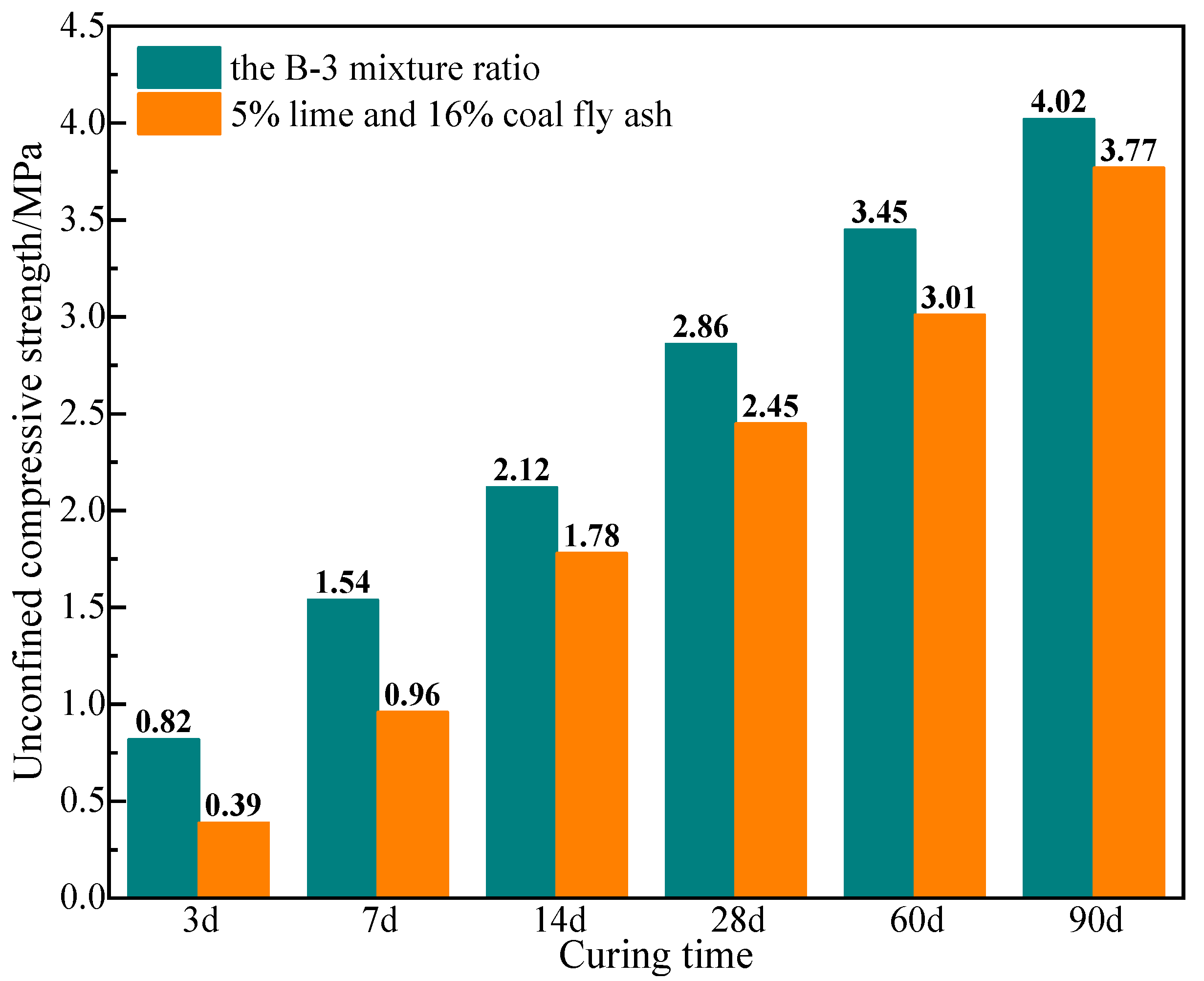
Standard specimens were prepared using the B-3 mixture ratio and the mix ratio of 5% lime and 16% coal fly ash, respectively. The unconfined compressive strength of specimens was measured at specific curing time. The results are presented in
Figure 5. The bending test was carried out on the specimens of group B-3 for 90 days.
According to the specifications outlined in JTGT F20-2015, titled as “Technical Guidelines for Construction of Highway Roadbases”, the industrial waste-based stabilizer or lime and coal fly ash-based stabilizer must exhibit a minimum strength of 0.6 MPa at 7 d. Furthermore, for both highway and first-class highway, a minimum strength requirement of 1.1 MPa is mandated. The bending test of the 90-day specimen shows that the splitting strength is 0.44 MPa, which meets the requirements of road construction engineering in North China. It is shown in
Figure 5 that the unconfined compressive strength of group B-3 specimens is higher than those of solidified soil with lime and coal fly ash at all curing times. The strength specimens prepared with the B-3 mixture ratio at 7 d reached 1.54 MPa, thus satisfying the strength criteria for highways of all levels. Noteworthy, the strength of the solidified soil demonstrates a progressive increase at extended curing age, reaching 2.86 MPa at 28 d and 4.02 MPa at 90 d. These values represent enhancements of 85.71% and 161.04%, respectively, when compared to the initial strength at 7 d. The observation underscores the significant potential for strength development in the system, with notable improvements during the middle and later stages.
3.5. Results of X-ray Diffraction Analysis
The curing agent and the saline soil were mixed according to the mixture ratio of B-3 but without adding water, and the powder sample obtained was used as the prototype mixture. The specimens from experimental group B-3, along with the saline soil and prototype mixture, were prepared and subjected to X-ray diffraction (XRD) analysis at 7 d, 28 d, and 90 d. The findings of the analysis are presented in
Figure 6.
The predominant phases present in the saline soil consist of quartz (SiO2), muscovite (KAl2(AlSi3O10)(OH)2), plagioclase (Na[AlSi3O8]-Ca[Al2Si2O8]), chlorite (Mg3[Si4O10](OH)2·Fe3(OH)6), and calcite (CaCO3).
The XRD patterns of the solidified soil samples predominantly exhibit non-hydration products. In the vicinity of 13°, the intensity of the diffraction peaks corresponding to chlorite initially increases and then decreases with advancing age. Subsequently, around 28°, the intensity of the diffraction peaks corresponding to plagioclase shows a progressive increase over time. Likewise, a notable change in the trend occurs around 21°, where the diffraction peak corresponds to calcite. The intensity of the diffraction peaks related to quartz also demonstrates variations within the ranges of 39°, 50°, and 60°. The observations indicate that, as the hydration age increases, a small proportion of less reactive substances also engage in the reaction.
Due to the relatively low content of the curing agent at only 20%, the formation of hydration products is limited, resulting in fewer prominent characteristic peaks in the figure. The XRD analysis of the solidified soils at 28 d and 90 d reveals the presence of diffraction peaks corresponding to various hydration products, namely, ettringite (3CaO·Al
2O
3·3CaSO
4·32H
2O), calcium silicate hydrate (Ca
5Si
6O
16(OH)·4H
2O), and Friedel’s salt (3CaO·Al
2O
3·CaCl
2·10H
2O). Furthermore, a weak and broad amorphous phase bulge is observed around 26°, indicating the presence of the amorphous C-S-H gel [
23,
24]. Interestingly, the diffraction peaks corresponding to Friedel’s salt are barely discernible in the spectra at 7 d, implying minimal formation of Friedel’s salt during the early stages of the reaction. Nevertheless, as the curing time progresses, the intensity of the diffraction peaks for all three products gradually increases, signifying a gradual accumulation of hydration products through the hydration reaction. Intriguingly, the intensity of the characteristic peaks corresponding to brunt lime (Ca(OH)
2), an important reactant, gradually decreases with an increase in curing time. The result shows that the content of brunt lime is gradually reduced during the whole period of hydration reaction, but it always exists.
The diffraction peaks attributed to dihydrate gypsum (CaSO4·2H2O) were evident in the spectra at prototype mixture and 7 d but were notably absent in the spectra at 28 d and 90 d. The finding indicates the complete consumption of dihydrate gypsum by the 28th day.
3.6. Results of SEM-EDS Analysis
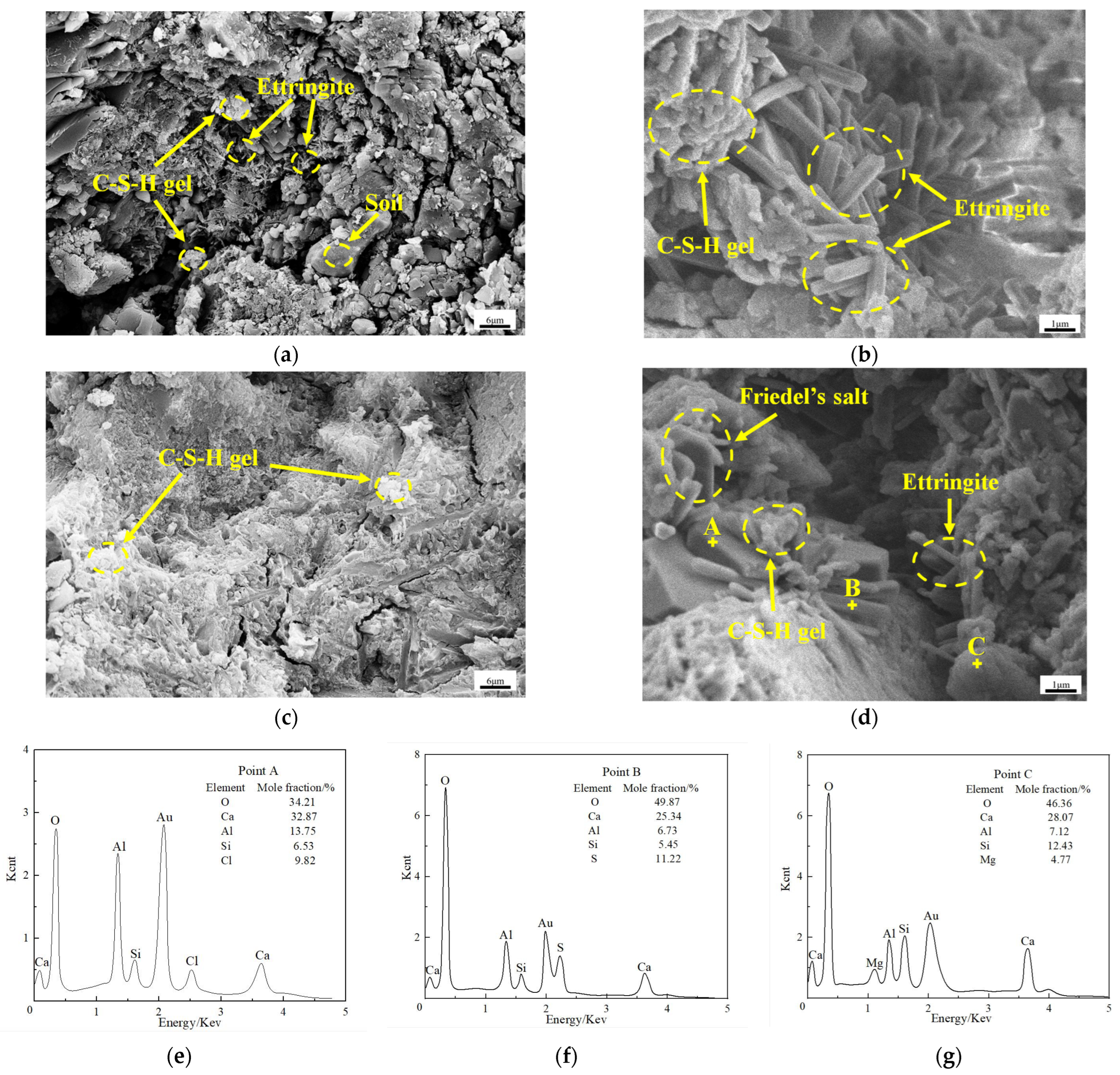
SEM-EDS analysis was performed on samples collected from the B-3 experimental group at 7 d and 90 d. The micro-morphology of the samples was examined, and the composition and relative proportions of the elements constituting the hydration products were determined at 90 d.
Figure 7a,b represent the samples at 7 d, while
Figure 7c,d represent the samples at 90 d. Additionally,
Figure 7e–g correspond to the EDS energy spectra obtained from points A, B, and C, respectively, as indicated in
Figure 7d. The findings of this analysis are presented in
Figure 7.
Based on the EDS energy spectrum and XRD analysis results depicted in
Figure 7, the discernible ortho-hexagonal lamellae observed at point A can be attributed to Friedel’s salt. The elongated and rod-like morphology observed at point B is indicative of ettringite (AFt) as the hydration product, whereas the amorphous structure observed at point C corresponds to the formation of calcium silicate hydrate gel (C-S-H gel).
It is shown in
Figure 7a,b that the solidified soil structure at 7 d exhibits a loose arrangement characterized by an abundance of unfilled pores and voids. These pores demonstrate notable size. Importantly, at this early stage, a substantial quantity of AFt and C-S-H gel have already been formed. The C-S-H gel covers the soil particles and AFt crystals, while the AFt crystals grow in a staggered manner within the framework established by the C-S-H gel. The presence of AFt plays a critical role in connecting and filling voids, facilitating the initial consolidation of the loose soil structure and contributing to a certain level of strength. However, it is worth noting that the degree of hydration in the solidified soil is still limited at the stage, with a significant amount of AFt remaining exposed on the external surface.
It is shown in
Figure 7c,d that the compaction of the solidified soil structure significantly enhances at 90 d compared to 7 d. There is a notable reduction in both the size and quantity of pores, leading to a substantial decrease in available space. At this stage, the AFt crystals are nearly completely encapsulated by the C-S-H gel, with only the C-S-H gel observed on the surface. AFt is found in only a few isolated voids and pores. Moreover, besides AFt and C-S-H gel, the solidified soil at 90 d also exhibits the presence of Friedel’s salt, which can integrate into the structure formed by the C-S-H gel together with AFt. The continuous generation of Friedel’s salt and AFt through the hydration reaction further are enveloped in the C-S-H gel, resulting in a substantial enhancement in the strength of the soil.
4. Discussion
As analyzed via XRD and SEM-EDS, AFt, C-S-H gel and Friedel’s salt are generated during the hydration reaction. The primary constituent of carbide slag is Ca(OH)
2, which facilitates the dissolution of Ca
2+ and OH
− ions (Equation (4)), thereby establishing an alkaline environment within the system. In the alkaline environment, the reactive components, SiO
2 and Al
2O
3, present in the GBF slag and coal fly ash undergo the cleavage of Si-O bonds and Al-O bonds, resulting in the liberation of silicate ions (SiO
32−) and aluminate ions (AlO
2−) (Equation (5)). These ions subsequently participate in the reformation of Si-O bonds and Al-O bonds, leading to the formation of silicon–oxygen tetrahedrons ([H
3SiO
4]
−) and aluminum–oxygen tetrahedrons ([H
3AlO
4]
2−) within the slurry [
25,
26] (Equations (6) and (7)). The reaction equations are as follows:
The [H
3SiO
4]
− undergoes a reaction with Ca
2+ ions, resulting in the formation of calcium silicate hydrate gel (C-S-H gel) (Equation (8)). Meanwhile, the [H
3AlO
4]
2− reacts with Ca
2+ ions, leading to the formation of calcium aluminate hydrate gel (C-A-H gel) (Equation (9)). FGD gypsum primarily consists of CaSO
4, which readily releases Ca
2+ and SO
42− ions when in contact with water (Equation (10)). However, the stable existence of C-A-H gel in the liquid phase is poor, as a portion of it reacts with SO
42− ions to produce AFt (Equation (11)), while another portion reacts with Cl
− ions, yielding Friedel’s salt and OH
− ions (Equation (12)). The reaction equations are as follows:
Sodium silicate, predominantly composed of Na2O·nSiO2, serves as an alkaline activator by facilitating the dissolution of silicate ions and OH− in water. The presence of OH− contributes to the alkaline environment, promoting favorable conditions for the system. Moreover, the active participation of SiO32− in the hydration reaction contributes to the early strength development of the structure.
Throughout the entire hydration process, carbide slag plays a vital role in providing Ca
2+ ions and an alkaline environment. The GBF slag and coal fly ash act as sources of active SiO
2 and Al
2O
3, while FGD gypsum supplies Ca
2+ and SO
42−. These four raw materials synergistically generate two primary hydration products: C-S-H gel and AFt. Saline soils inherently contain SiO
2, Al
2O
3, and CaO. Upon interaction with water, a portion of free calcium oxide reacts to form Ca (OH)
2 (Equation (13)) [
27]. In the alkaline environment, reactive SiO
2 and Al
2O
3 are activated, leading to the formation of C-A-H gel and C-S-H gel. Furthermore, soluble SO
42− in the soil reacts with C-A-H gel, resulting in the formation of AFt. Both C-S-H gel and AFt exhibit a positive charge, enabling them to adsorb a fraction of soluble Cl
− [
28]. Concurrently, another portion of Cl
− reacts with C-A-H to generate Friedel’s salt and OH
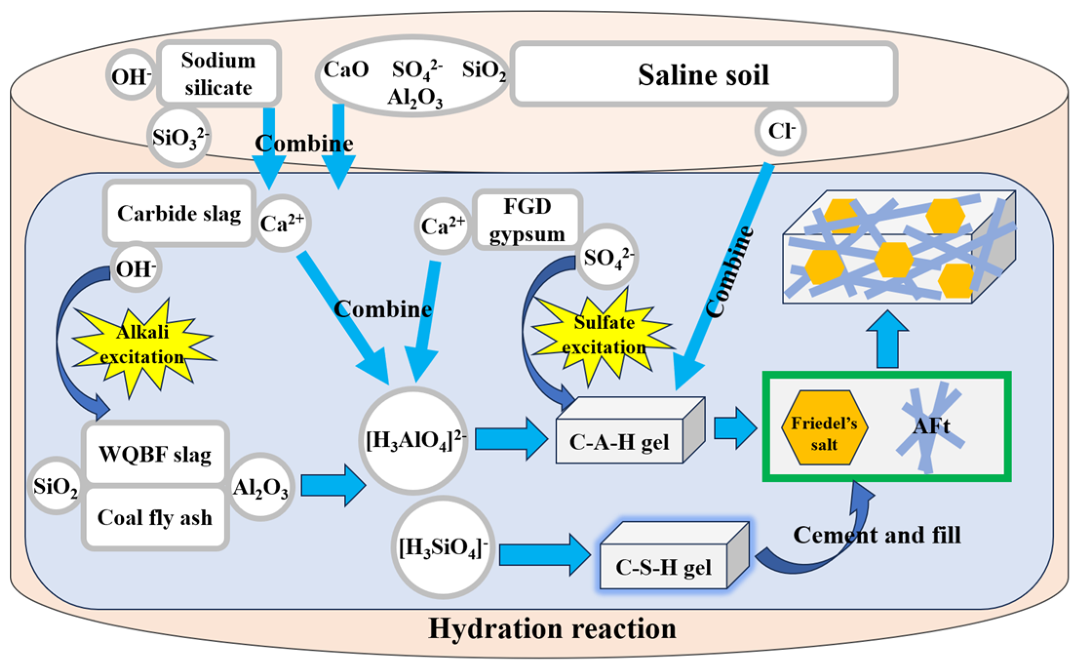
−, thereby facilitating the formation of hydration products and maintaining an alkaline environment. Consequently, the strength of the solidified soil is derived from two components: the cementitious system comprising carbide slag, GBF slag, coal fly ash, and FGD gypsum as well as the reaction between curing agent and saline soil.
The C-S-H gel, a significant hydration product, possesses amorphous characteristics and exhibits cementitious properties. Through the influence of intermolecular forces, it effectively envelops and binds adjacent materials, thereby connecting the dispersed structure and forming a cohesive whole. Consequently, the solidified soil achieves a satisfactory level of strength during the early stages. As the hydration reaction proceeds, the needle-rod-shaped AFt crystals and regular hexagonal Friedel’s salt continuously form and fill the pore structure. The process enhances the compactness of the soil structure and improves the compressive strength of the solidified soil. Concurrently, the content of soluble SO
42− and Cl
− in the saline soil decreases, thereby enhancing the soil’s resistance to salt expansion and collapsibility. It is worth mentioning that the stability of the hydration products is very good. In 90 days, the diffraction peaks corresponding to hydration products did not weaken in the XRD pattern, and the amount of hydration products seen by SEM only increased and did not decrease. The reaction mechanism is showed in
Figure 8.
5. Conclusions
In the curing agent system, sodium silicate has been identified as a more suitable activator. The optimized mixture ratio consists of 4% sodium silicate, 26% carbide slag, 25% GBF slag, 37% coal fly ash, and 10% FGD gypsum. Under the specific conditions, the unconfined compressive strength of the solidified soil at 7 d reaches 1.54 MPa, satisfying the construction requirements for various highway levels. Notably, the strength further develops over time, reaching 2.86 MPa at 28 d and 4.02 MPa at 90 d, demonstrating a notable increase in strength during the middle and later stages.
XRD and SEM-EDS analysis reveals that the primary hydration products formed include AFt, C-S-H gel, and Friedel’s salt. SEM-EDS analysis unveiled the correspondence of the needle-rod-shaped products to AFt, the correspondence of the ortho-hexagonal layered products to Friedel’s salt, and the correspondence of the amorphous products to C-S-H gel. The C-S-H gel effectively enveloped the soil particles, AFt, and Friedel’s salt, thereby fostering the compaction of the structure. The AFt and Friedel’s salt were evenly distributed within the structure formed by the C-S-H gel, playing a crucial role in pore filling and interconnecting the soil particles. The reactive SiO2 and Al2O3 in saline soil, actively participate in the hydration reaction. Soluble Cl− and SO42− ions undergo reactions with the C-A-H gel, resulting in the formation of Friedel’s salt and AFt. Consequently, in the particularly cementitious material system, the saline soil itself actively engages in the reaction system and supplies the requisite Cl− ions for the formation of Friedel’s salt. Because there are many Cl− and SO42− ions involved in the saline reaction system, the fabricated curing agent is suitable for both chlorine and sulfate saline soils. By Comparing the saline soil, the curing agent may have a better soil stabilization performance for clay or silty soils because there is no negative effect of saline ions.


 ,
, 


