Abstract
Silicon carbide and silicon nitride materials were intensively studied in the end of the past century, yet some aspects of its physical chemistry require investigation. The strength characteristics of Si3N4-SiC refractories are moderate; however, these materials sometimes demonstrate “stress–strain” behavior, more typical for composite materials than for the brittle ceramics. These materials may be considered to be ceramic composites because they consist of big grains of silicon carbide surrounded by small grains of silicon nitride, with strict interfaces between them. There is no direct certainty whether Si3N4-SiC compositions may be called composite materials or brittle ceramic materials from the viewpoint of mechanics and strength. The balance of α/β modifications of silicon nitride in Si3N4-SiC composite material and, the occurrence and the role of silicon oxynitride Si2ON2 are also a matter of scientific interest in processing of Si3N4-SiC composite material. The same may be said about the particles of silicon nitride between the grains of silicon carbide—there is no direct understanding whether silicon nitride grains will be isometric grains or needle-like crystals.
1. Introduction
Silicon carbide and silicon nitride materials in the ceramic world were at the center of attention in the latter part of the past century [1]. It was considered that a lot of problems would be solved with the help of these materials. Probably the most ambitious aim was an aircraft gas turbine engine made from Si3N4 and SiC materials. At that time, the aim was not realized; however, the materials have found many interesting industrial applications. The total world market of Si3N4-SiC materials in our time is more than 60 thousand tn; the major consumption is in the Al industry [2], followed by copper metallurgy [3], incinerators (WTE) [4], and kiln furniture.
Si3N4-SiC ceramic materials and refractories have been fabricated on an industrial scale for more than 40–50 years [5], yet not everything is known even in processing. Silicon-nitride-bonded silicon carbide materials may be considered as composite materials, because they consist of big grains of silicon carbide surrounded by small, sometimes needle-like grains of silicon nitride with strict interfaces between them. However, the properties of silicon carbide and silicon nitride are very similar, and they cannot be attributed to composite materials from this viewpoint.
The mechanical properties of coarse-grained Si3N4-SiC compositions are reported in [6,7]. There is no direct certainty whether Si3N4-SiC materials may be called brittle ceramic materials or composite materials from the viewpoint of mechanics and strength. The strength characteristics of Si3N4-SiC refractories are moderate; however, these materials demonstrate “stress–strain” behavior more typical for composite materials than for the brittle ceramics.
The balance of α/β modifications of silicon nitride in the composite material and the occurrence and the role of silicon oxynitride, Si2ON2, also are a matter of scientific interest in the processing of Si3N4-SiC composite material. The same made be said about the particles of silicon nitride between the grains of silicon carbide, i.e., whether they will be small relatively isometric grains or needle-like crystals; do they grow in the course of solid–gas reactions, or due to gas–gas phase reactions?
The gradients of porosity, from the middle to the corners in relatively thick slabs, may be attributed to the fact that at least 30% of silicon nitrides originate between the grains of SiC due to evaporation of silicon and the gas-phase exothermic reaction of nitridation [8].
Silicon-nitride-bonded silicon carbide materials may be produced in static and flowing nitrogen atmospheres (depending on the type of furnace). Usually, the materials produced in furnaces with a static atmosphere contain minor concentrations of silicon oxynitride (<0.3%). The materials produced in furnaces with a flowing nitrogen atmosphere contain silicon oxynitride in concentrations from 0.5% to 5–7% (there is information about Si3N4-SiC materials with a Si2ON2 concentration of 8.4%) [9].
There are discussions as to whether a silicon oxynitride admixture is useful or harmful for the oxidation resistance and corrosion resistance of Si3N4-SiC materials. Until now, it has been considered [9,10] that silicon oxynitride content below 3–5% in Si3N4-SiC materials is not harmful for oxidation resistance and corrosion resistance. The information on the shape of silicon oxynitride grains or layers in Si3N4-SiC compositions, and where these grains and layers are located, is limited.
One aim of this research was to investigate the composition of the material produced in static and flowing nitrogen atmospheres (in the lab and in industrial furnaces), to investigate the morphology of silicon oxynitride particles and to find out where these particles and layers are formed in silicon-nitride-bonded silicon carbide. The other aim was to investigate the mechanical characteristics of silicon-nitride-bonded silicon carbide materials with different grain dimensions and to evaluate whether these materials demonstrate the elastic mechanical behavior of brittle ceramic materials or the elastic-plastic behavior of composite materials.
2. Materials and Methods
The current paper covers the investigations of the author, together with co-authors [6,7,8]; some of the information was published earlier, some information is not published yet.
The samples were prepared from commercially available α-SiC starting powder (SiC > 98%, Fe < 0.3%, C < 0.4%) and silicon powder KR-0 (Si > 98%, Fe < 0.5%, Al < 0.4%, Ca < 0.4%, total admixtures < 1.2%, average grain size—40–50 μm). Two types of pressing mixes were made from three grain size fractions of silicon carbide: coarse-grained mix, consisting of grain fractions F 7–14 (1600–3000 μm), F 36–70 (200–500 μm), and F80–180 (63–160 μm), and medium-size-grain mix, consisting of grain fractions F36 (500–630 μm), F120 (100–125 μm), and F400 (14–20 μm).
The medium-size pressing mix was dry pressed with polyvinyl alcohol temporary binder at 5 MPa pressure; the green shapes were dried and installed for firing in the furnace with a static nitrogen atmosphere. The temperature of the heat treatment in nitrogen was 1450 °C; the time at maximum temperature was 2 h.
The pressing mixes were dry pressed and vibropressed; the green shapes were dried and installed for firing in the furnace with a flowing nitrogen atmosphere and with a static nitrogen atmosphere (with prior vacuum pumping).
The open porosity and apparent density of materials were determined according to ISO 5017:2013-01 [11]; the cold crushing strength and bending strength (as well as “stress–strain curves”) were determined according to ISO 10059-2:2003 [12] and ISO 5014-97 [13] on an Instron HVL testing machine; the pore size distribution was determined by mercury absorption according to ASTM C-493-98.
The chemical composition of the materials was determined by standard wet chemistry methods (SiC, Si, SiO2, CaO, Fe2O3, Al2O3) and by XRD (SiC, Si, SiO2, Si3N4); the determination of nitrogen and oxygen was performed using the LECO method. The SiC content was determined by wet chemistry and by XRD.
The contents of silicon nitride and silicon oxide were calculated from values of nitrogen and oxygen, determined by the LECO method and by XRD; silicon oxynitride, Si2ON2, and α- and β- modifications of silicon nitride of the current research were determined by XRD (Thermo ARL X-TRA, Thermo Fisher Scientific, Basel, Switzerland), CuKα, λ = 1.5418 Å, 0.2°/minute. The SiO2 concentration was calculated from the oxygen value, received by subtraction of oxygen from calcium, aluminium and iron oxides.
Structures were analyzed at TESCAN X-max SEM (TESCAN, Brno, Czech Republic) with EDX Oxford instruments microprobe analyzer microscope (Oxford Instruments, Abingdon, United Kingdom) and on SEM JSM-6510LV (Thermo Fisher Scientific, Tokyo, Japan).
3. Physical and Chemical Aspects of Processing
3.1. Reactions in Processing of Silicon-Nitride-Bonded Silicon Carbide Materials
The technology of silicon-nitride-bonded silicon carbide comes from the technology of reaction-sintered silicon nitride. Silicon powder is mixed with the grains of a silicon carbide (Figure 1a); the green shape of silicon and silicon carbide powder is heat treated in a nitrogen atmosphere; gaseous nitrogen reacts with silicon, and the ready product is silicon-nitride-bonded silicon carbide material (Figure 1b).
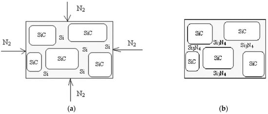
Figure 1.
Schematic illustration of Si3N4-SiC processing: (a) before and in the process of the firing, (b) after the firing.
Nitrogen can react with solid silicon, with molten silicon, and with gaseous silicon.
3 Si (s,l,g) + 2 N2 (g) = Si3N4 (s)
ΔQ (1400 °C) = 740 kJ/mol
It is considered that at low temperatures, a film of silicon nitride is formed on the surfaces of solid particles of silicon. The formation of a film may stop the reaction, but it is believed [14,15] that the silicon nitride film is not continuous, and there are gaps and cracks through which nitrogen can penetrate to solid or liquid silicon. Silicon may evaporate through these gaps and cracks. The volatility of silicon is high, while the volatility of the resulting silicon nitride is very low, so in case of a nitrogen reaction with gaseous silicon, silicon nitride will deposit on grains of silicon carbide.
The volume effect of Reaction (1) is [7]
ΔV/V = V(Si3N4)/3V(Si) = 1.2
The weight effect of the reaction is [7]
Δm/m = m(Si3N4)/3m(Si) = 1.67
The positive value of volume effect of Reaction (1) means that the reactants occupy more space than the starting powders. Reaction (1) proceeds with positive volume effect and positive weight effect [7]. This means that 1 mole of appearing silicon nitride occupies a 20% larger volume than the 3 initial moles of silicon that means the diminishing of porosity and giving strength.
Due to the positive weight effect of Reaction (1), the weight of the sintered materials is bigger than the weight the green shapes. The shrinkage in the course of the reaction-sintering process of Si3N4-SiC is below 1%, but the porosity of the materials diminishes due to the positive volume effect of reaction.
3.2. On the Ratio of α-Si3N4 to β-Si3N4 Modifications in Si3N4-SiC Materials and Possible Reaction of Silicon Carbide with Nitrogen
There is no direct certainty on the question as to what modifications of silicon nitride occur in the course of the reaction of silicon and nitrogen in different conditions. F. Riley states [5] that α-Si3N4 has a needle-like origin, while β-Si3N4 crystallizes in a more isometrical form. The grains of α-SiC initially have bigger dimensions. One point of view suggests [5] that the main product of the reaction of solid silicon with gaseous nitrogen is β-Si3N4 (marked “3” in Figure 2), and the main product of the reaction of gaseous silicon with gaseous nitrogen is α-Si3N4 (marked “2” in Figure 2). Per [14,15,16] there is no direct information as to what modification of silicon nitride gives Reaction (1) of liquid silicon with nitrogen. Another thing is that the α-Si3N4 structure can accommodate small amounts of oxygen atoms [5,14,15,16] and is more likely to occur via volatilization and saturation of resulting silicon nitride.
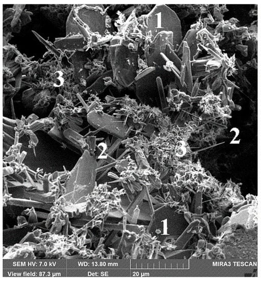
Figure 2.
Structure of Si3N4-SiC ceramic refractory materials: 1—α-SiC; 2—α-Si3N4; 3—β-Si3N4.
The average grain size of isometric crystals of silicon nitride is from 1 μm to 3–5 μm, the average diameter of needle like crystals of silicon nitride is from 0.5 μm to 2–3 μm, and the length of needle-like crystals is from 7–10 to 50 μm (Figure 2). Traditionally, the needle-like shape of silicon nitride crystals is attributed to α modification [5,14,15,16].
The crystal lattice parameters [1,5,17] of the α and β modifications of silicon nitride are very similar (Table 1), but it is considered that the shapes of α-Si3N4 and β-Si3N4 particles differ. Usually the shape of β-Si3N4 particles is close to isometric or tends to be rod-like short prismatic with L/d from 1 to 2–2.5 (Figure 3a). The shape of α-Si3N4 particles is elongated with needle-like crystals, having L/d > 10–20 (Figure 3b).

Table 1.
Lattice parameters and density of α and β modifications of silicon nitride [1,5,17].
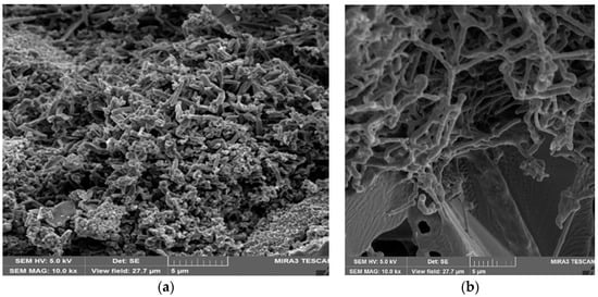
Figure 3.
The structures of Si3N4-SiC materials: (a) the structure with isometrical grains of silicon nitride; (b) the structure with needle-like grains of silicon nitride.
Our experimental data (Table 2) show that the α/β ratios of silicon nitride, synthesized in lab conditions in a static atmosphere and in industrial conditions [6,7,8] in a flowing atmosphere of nitrogen, differ considerably. Large amounts of α-needle-like crystals of silicon nitride are present in materials produced in a flowing atmosphere. This suggests that traces of oxygen (in a flowing atmosphere of nitrogen) promote the formation of α-Si3N4.

Table 2.
Chemical and phase compositions of Si3N4-SiC materials, processed in static and flowing atmospheres of nitrogen at 1450 °C [6,7,8].
According to [7], the α/β ratio of silicon nitride may vary from 1.13 to 2.7. According to Skybakmoen statistics [9,18,19], the range of the α/β ratio is even higher—up to 13 and even 15. In his investigation, the β modification of silicon nitride crystallizes mainly in the centers of the shapes. According to our results, in a static atmosphere of nitrogen, the α/β ratio of silicon nitride is 0.29 (Table 2).
Returning to the problem—what modifications of silicon nitride appear from solid, liquid and gaseous silicon according to Reaction (1)—we can state that it looks like the predominant appearing modification due to reaction with gaseous silicon is the alpha modification, and it looks like the predominant modification appearing at temperatures below the melting point of silicon, due to reaction with solid silicon, is the beta modification. However, there is always the possibility for both modifications to appear. Silicon oxynitride appears as a minor constituent (Table 2) in the case of a flowing nitrogen atmosphere.
Also, it is necessary to note that usually in lab and industrial practice, the dimensions of the silicon starting powder in green mix is 20–60 μm. It is more or less obvious that α-crystals of silicon nitride with diameter 0.3–2 µm appear from silicon grains with diameter 40–60 µm via gaseous reaction. However, we did not manage to find in the literature the mechanism of transformation of silicon grains with diameter 40–60 µm to 2–5 µm grains of β-crystals of silicon nitride.
Reaction (1) is not the only reaction in the processing of silicon-nitride-bonded silicon carbide. SiC may also react with nitrogen [5],
giving silicon nitride and carbon, and the appearing carbon may react with minor oxygen. Reaction (5) may take place, though its rate is not so high, compared with the reaction of silicon and nitrogen. An extra 12–15 h of firing in a nitrogen atmosphere at 1400–1450 °C gives a decrease in SiC content of 3%, and an increase in silicon nitride content of 2% [7].
3 SiC + 2 N2 = Si3N4 +C
3.3. On the Appearance of Silicon Oxynitride in Si3N4-SiC Materials
Si3N4-SiC materials may be produced in static and flowing nitrogen atmospheres. Minor concentrations of oxygen in flowing nitrogen give a small concentration of silicon oxynitride in the materials produced in a flowing nitrogen atmosphere.
In the presence of minor oxygen concentration (always existing in big furnaces with a flowing atmosphere of nitrogen), silicon may react with oxygen, giving volatile silicon monoxide SiO.
Si (s,l,g) + ½ O2 → SiO (g)
The possible reactions are:
2 Si + 1/2 O2 + N2 = Si2ON2
2 SiO + N2 → Si2ON2
SiC + O2 + N2 → Si2ON2 + CO
The silicon oxynitride phase is recorded by XRD (Table 2, Figure 4) in amounts of up to 3.5%; sometimes it forms small separate particles of up to 3–7 μm between silicon nitride grains, surrounding big silicon carbide grains. However, more frequently, the Si2ON2 phase forms layers on silicon nitride crystals. The dimensions of these layers are 2–5 μm (Figure 4).
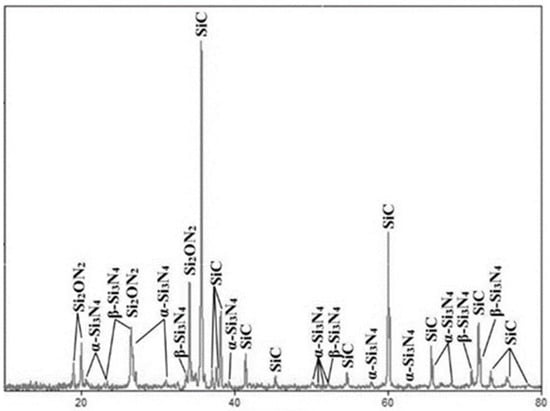
Figure 4.
XRD of Si3N4-SiC materials, produced in a flowing nitrogen atmosphere.
The silicon oxynitride phase occupies the outer periphery parts of pores, formed by small silicon nitride crystals. The silicon oxinitride phase may form thin layers on silicon nitride crystals, and may form small separate crystals.
Silicon in the gas phase may react with residual oxygen, with the formation of silicon oxide and silicon monoxide (Reaction (5)), but may react (Reactions (6) and (7)) with oxygen and nitrogen in the gas phase, giving silicon oxynitride. Reactions (6) and (7) most likely give small grains of silicon oxynitride in the pores and caverns. The intermediate layers of silicon oxynitride are formed on the surface of silicon nitride grains, also due to Reactions (6) and (7) in the gas phase.
This picture gives a good explanation why there exist the thin layers (2–3 μm) of silicon oxynitride on the surfaces of silicon nitride grains (Figure 4), because the film of silicon oxinitride may form on the surface of silicon nitride crystals in the last turn, being deposited from the gas phase.
The area of existence of silicon oxynitride is narrow [1,5]. There are publications [20] describing the synthesis of silicon oxynitride films for electronics. The information on bulk silicon oxynitride materials and on materials that contain big contents of silicon oxynitride is limited.
However, there are discussions whether silicon oxynitride admixtures in silicon nitride and Si3N4-SiC materials are useful or harmful for oxidation resistance and corrosion resistance. Thonnesen [10] considers that oxygen atoms in the crystal structure of silicon nitride in Si3N4-SiC materials prevent rapid oxidation of materials during oxidation tests.
Skybakmoen [9,18,19] made a series of experiments on corrosion testing of Si3N4-SiC materials in cryolite melt and stated that silicon oxynitride admixtures of up to 5–8% are not harmful for corrosion resistance.
Silicon oxynitride appears as a minor constituent (Table 2) in the case of a flowing nitrogen atmosphere. In industrial processing of Si3N4-SiC materials, the formation of 2–5% silicon oxynitride [7,8] (and sometimes up to 7–8% [9,18,19]) is a conventional by-process.
3.4. The Heat Effect of Nitration and the Structure of Silicon Nitride-Silicon Carbide Bulk Materials
Usually in lab samples with dimensions not exceeding 20–50 mm, there is no influence of the heat effect of nitration (1) on the gradients of porosity and composition. Skybakmoen [9,18,19] underlines that industrial silicon carbide–silicon nitride samples with thickness up to 70–100 mm and linear dimensions up to 650–700 mm—have certain gradients of porosity (Figure 5).
As mentioned previously, the Reaction (1) of silicon and nitrogen is strongly exothermic (2) [1,2]. It is known [21] that in the case of overheating due to the uncontrolled exothermal effect, the temperature in the samples might be higher than the temperature in the furnace. According to Hughes [10], the temperature in the middle of a silicon disk with radius 5 cm may be up to 1400–1440 °C (while the temperature in the furnace is 1350–1370 °C.
According Honig and Tomooka [22,23], the partial pressure of silicon vapors above silicon at a temperature of 1337 °C (below the melting point of silicon) is 10−4 torr (0.013 Pa), while at 1472 °C (above the melting point of silicon), it is 10−3 torr (0.13 Pa). Some silicon nitride is formed during the reaction of nitrogen with solid or liquid silicon (and also due to the diffusion of nitrogen through silicon nitride film), and some silicon nitride is formed due to the reaction of nitrogen with silicon vapor.
In the processing of relatively big shapes, the difference in temperature of 40–60 °C might be critical. When the temperature reaches the melting point of silicon, the vapor pressure of silicon increases approximately 10 times, as volatile silicon is much more reactant to gaseous nitrogen, a sort of self-propagating chain process: as temperature increases, the silicon vapor pressure increases; that gives rise to an increase in the reaction rate and heat release; that increases the temperature, and so the process goes, as illustrated in Figure 6.
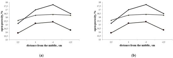
Figure 6.
The examples of porosity gradients in Si3N4-SiC 70 mm thick blocks: (a) according to Skybakmoen [9,18,19]; and (b) Yurkov [7,8].
The gradients of porosity in Si3N4-SiC materials appear because of the evaporation of silicon in the zone with the maximum temperature and the diffusion of silicon vapor to the zone with the lower concentration of silicon vapor—that is, to the periphery of the shapes—with the following reaction in the gaseous phase and the appearing silicon nitride. Silicon nitride condenses in the pores on the surfaces of existing particles, but predominantly at the peripheral parts of the shapes (Figure 7).
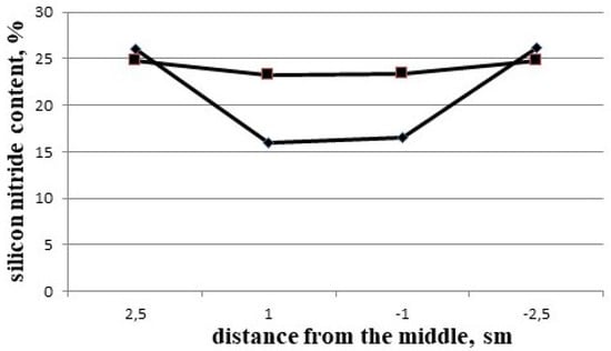
Figure 7.
The gradients of silicon nitride concentrations in different Si3N4-SiC blocks [7].
Figure 8 shows the schematic illustration of self-propagating chain process during Si3N4-SiC processing.
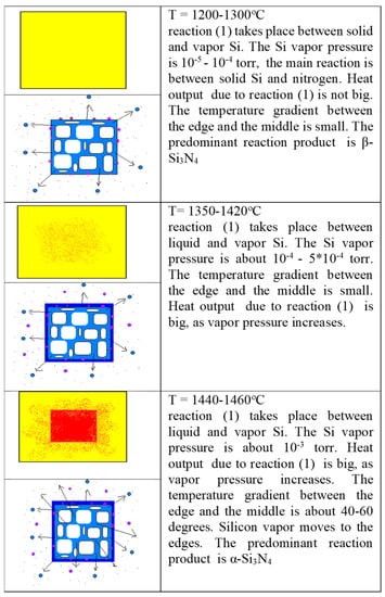
Figure 8.
Schematic illustration of self-propagating chain process during Si3N4-SiC processing [8].
The difference in porosity (Table 3) near the surface and in the middle (Figure 6) [7,8,17,18] might be up to 5–6%.

Table 3.
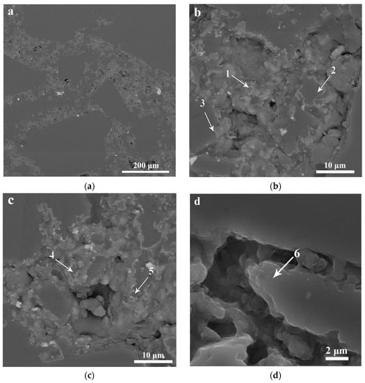
Contents of nitrogen, silicon, and oxygen obtained from EDX spectra of Si3N4-SiC material, produced in the atmosphere of flowing nitrogen. Spectra were taken at points 1–6 marked on Figure 5b–d.
The pore size distribution also differs in the middle and near the surface (Figure 9). In the middle of the 70 mm N-SiC block, there is a bi-modal distribution with predominant pore sizes 0.6–0.7 µm and 3 µm. Near the surface, there is a classical mono-modal distribution with pore size 1 µm. It looks like the appearing silicon nitride grains form a uniform and fine pore structure (Figure 3b and Figure 10a) between big grains of silicon carbide.
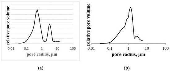
Figure 9.
Pore size distribution in Si3N4-SiC material in the middle (a) and near the surface (b).
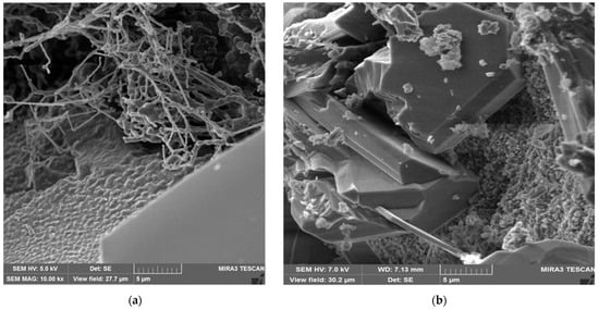
Figure 10.
The typical structures of silicon-nitride-bonded silicon carbide: (a) peripheral part; (b) in the middle.
Taking into account the difference in porosity between the center and the peripheral part of up to 2–2.5% (Table 3, Figure 6a,b) and the difference in Si3N4 concentration of up to 8–9% (Table 2 and Table 3, Figure 7), it is possible to suggest that up to 15–17% of the silicon in the vapor phase may move from the middle to the periphery of the shapes in the course of processing, and the difference in porosity and silicon nitride concentration in Si3N4-SiC materials (Figure 10a,b) is a consequence of the proposed mechanism of diffusion and partial evaporation of silicon vapor.
3.5. Ratio of Si3N4 to SiC in Silicon Nitride-Silicon Carbide Materials and Mechanical Characteristics
It is not easy to say that there is a certain optimum concentration between silicon carbide and silicon nitride that gives the optimum properties of materials. This question also addresses the next paper (part 2), devoted to the corrosion resistance of silicon nitride-silicon carbide materials. The concentration dependency of density is more or less obvious (Figure 11a)—the more binding silicon nitride grains fill in the spaces between the coarse grains of silicon carbide, the greater the density. The porosity of materials decreases as well, due to the positive volume Effect (3) of Reaction (1). The green shapes with different silicon content have more or less similar porosity. The apparent density of the compositions increases due to positive weight Effect (4) of Reaction (1); consequently, there is an increase in the strength (Figure 11b).
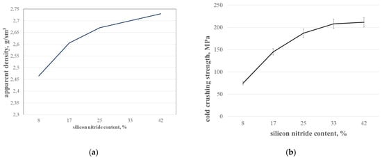
Figure 11.
Apparent density (a) and cold crushing strength (b) of SiC-Si3N4 compositions with different Si3N4 content.
The increasing of silicon nitride concentration will lead to a composition where silicon carbide filler will become discontinuous, so the useful properties of silicon carbide might not have an effect. We have no information on the increase in Si3N4 concentration in Si3N4-SiC materials above 40%.
Usually, monolithic structural ceramics deform in a brittle manner [24,25]; the particulate ceramic matrix composites show higher stress to failure behavior, and the stress–strain curve is a little bit more steep. For continuous fiber-reinforced ceramic matrix composites, the failure is of a non-catastrophic type, and there is a certain percentage of elongation in fiber-reinforced ceramics.
In the case of silicon-nitride-bonded silicon carbide materials (in our case—Table 4, sample 1, cut off near the surface), the picture is a little bit complicated: the stress–strain behavior at bending is brittle (Figure 12a), while at compression, the stress–strain curve shows composite behavior (Figure 12b).

Table 4.
Porosity and composition of Si3N4-SiC near the surface and in the middle (the width of the shape is 70 mm) [7].
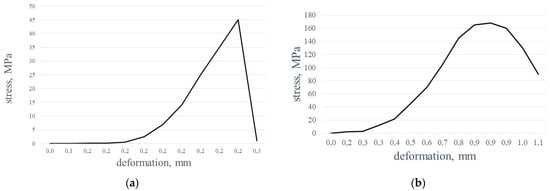
Figure 12.
Stress–deformation curves for Si3N4-SiC materials: (a) bending; (b) compression.
4. Conclusions
Due to the exothermal effect of reaction, the temperature in the middle of the shapes in the course of processing may be higher compared with the temperature near the surface, depending on the thickness of the shapes and the rate of heating.
The difference in temperatures within ceramic shapes promotes the excessive volatility of silicon, which moves from the middle of the shapes to periphery. The gradients of porosity and silicon nitride concentration may appear due to the movement of gaseous silicon from the middle to the surface of materials having relatively large thickness.
Usually, a silicon oxynitride admixture is an inevitable by-product in Si3N4-SiC materials, produced in furnaces with flowing nitrogen atmospheres. Silicon oxynitride may be present in Si3N4-SiC materials, either in the form of small grains in the pores and cavities between silicon nitride grains or in the form of thin layers on the surfaces of silicon nitride grains. It looks like the silicon oxynitride admixture does not affect the properties of Si3N4-SiC materials for Al reduction cells (although not everything is clear with the influence of silicon oxynitride).
Ceramic Si3N4-SiC materials demonstrate the “stress–strain” behavior more typical of composite materials than brittle ceramics.
Funding
This research received no external funding.
Informed Consent Statement
Not applicable.
Data Availability Statement
Not applicable.
Acknowledgments
The author is grateful to colleagues from the Voljsky plant and to Anton Nashekin (Lomonosov Moscow state university) for discussions and consultations.
Conflicts of Interest
The author declares no conflict of interest.
References
- Jack, K.H. Sialons and related nitrogen ceramics. J. Mater. Sci. 1976, 11, 1135–1158. [Google Scholar] [CrossRef]
- Sørlie, M.; Øye, H. Cathodes in Aluminium Electrolysis, 3rd ed.; Aluminium-Verlag: Düsseldorf, Germany, 2010; p. 662. [Google Scholar]
- Yurkov, A. Refractories for the Metallurgy of Copper. In Copper from the Mineral to the Final Application; IntechOpen: London, UK, 2022. [Google Scholar] [CrossRef]
- Tonnesen, T.; Telle, R.; Breuers, M. Oxidation Resistance of SiC Based Refractory Lining in steam Atmospheres—Material Properties and Testing Methods. In Proceedings of the 47th International Colloquium on Refractories, Aachen, Germany, 28–29 September 2005; pp. 214–217. [Google Scholar]
- Riley, F. Structural Ceramics. Fundamentals and Case Studies; Cambridge University Press: Cambridge, UK, 2009; p. 405. [Google Scholar]
- Danilova, O.; Dovgal, A.; Yurkov, A.; Doroganov, V.; Evtushenko, E. Si3N4-SiC materials—Properties and physical chemistry aspects of processing. In Proceedings of the 57th International Colloquium on Refractories “Refractories for Metallurgy”, Aachen, Germany, 24–25 September 2014; pp. 49–53. [Google Scholar]
- Yurkov, A.; Danilova, O.; Dovgal, A. N-SiC Side Lining—Variations of materials structure. Light Met. 2014, 2016, 1245–1249. [Google Scholar]
- Yurkov, A.; Danilova, O.; Dovgal, A. SiC side lining of reduction cells—Aspects of physical chemistry in processing and degradation. In Proceedings of the 11th Australasian Aluminium Smelting Technology Conference, Dubai, United Arab Emirates, 6–11 December 2014; Welch, B., Scillos-Kazakos, M., Eds.; UNSW: Sidney, NSW, Australia, 2014. ISBN 978-0-7334-3518-8, 23W4. [Google Scholar]
- Skybakmoen, E.; Wang, Z.; Grande, T. The influence of microstructure of Si3N4-SiC sidelining materials on chemical/oxidation resistance behavior tested at laboratory scale. In Proceedings of the 11th Australasian Aluminium Smelting Technology Conference, Dubai, United Arab Emirates, 6–11 December 2014; Welch, B., Scillos-Kazakos, M., Eds.; UNSW: Sidney, Australia, 2014. ISBN 978-0-7334-3518-8, 22W3. [Google Scholar]
- Tonnesen, T.; Telle, R. Refractory Corrosion in Industrial Waste Incineration Proceses. Refract. WORLDFORUM 2009, 1, 71–76. [Google Scholar]
- ISO 5017:2013; Dense Shaped Refractory Products—Determination of Bulk Density, Apparent Porosity and True Porosity. ISO—International Organization for Standardization: Geneva, Switzerland, 2013.
- ISO 10059-2:2003; Dense, Shaped Refractory Products—Determination of Cold Compressive Strength—Part 2: Test with Packing. ISO—International Organization for Standardization: Geneva, Switzerland, 2003.
- ISO 5014:1997; Dense and Insulating Shaped Refractory Products—Determination of Modulus of Rupture at Ambient Temperature. ISO—International Organization for Standardization: Geneva, Switzerland, 1997.
- Mangels, J.A. Effect of rate-controlled nitriding and nitriding atmospheres on the formation of reaction-bonded Si3N4. Am. Ceram. Soc. Bull. 1981, 60, 613–617. [Google Scholar]
- Moulson, J.A. Reaction bonded Silicon Nitride: Its formation and properties. J. Mater. Sci. 1979, 14, 1017–1051. [Google Scholar] [CrossRef]
- Andrievsky, R.; Spivak, I. Silicon Nitride and Silicon Nitride Based Materials, Moscow. Metallurgiya 1984, 136. [Google Scholar]
- Hardy, D.; Jack, K.H. Crystal Structures of Silicon Nitride. Nature 1957, 180, 332–333. [Google Scholar] [CrossRef]
- Skybakmoen, E.; Stoen, L.; Kvello, J.H.; Darrel, O. Quality evaluation in Nitride bonded Silicon Carbide Sidelining Materials. Light Met. 2005, 4, 773–778. [Google Scholar]
- Skybakmoen, E.; Kvello, J.; Darrel, O.; Gudbransen, H. Test and analysis of nitride bonded SiC sidelining materials: Typical properties analyzed 1997–2007. Light Met. 2008, 2008, 943–948. [Google Scholar]
- Hänninen, T.; Schmidt, S.; Jensen, J.; Hultman, L.; Högberg, H. Silicon oxynitride films deposited by reactive high power impulse magnetron sputtering using nitrous oxide as a single-source precursor. J. Vac. Sci. Technol. A 2015, 33, 05E121. [Google Scholar] [CrossRef]
- Hughes, G.; Mcgreavy, C.; Mezkin, J. A theoretical model of the manufacture of reaction-bonded silicon nitride with particular emphasis on the effect of ambient reaction temperature and compact size. J. Mater. Sci. 1980, 15, 2345–2353. [Google Scholar] [CrossRef]
- Honig, R.E.; Kramer, D.E. Vapor pressure data for More Common Elements. RCA Rev. 1969, 30, 285. [Google Scholar]
- Tomooka, T.; Shoji, Y.; Matsui, T. High Temperature Vapor Pressure of Si. J. Mass Spectrom. Soc. Jpn. 1999, 47, 49–53. [Google Scholar] [CrossRef]
- Rice, R. Mechanical Properties of Ceramics and Composites. Grain and Particle Effects; CRC Press: Boca Raton, FL, USA, 2000; p. 712. [Google Scholar]
- Rosso, M. Ceramic and metal matrix composites: Routes and properties. J. Mater. Process. Technol. 2006, 175, 364–375. [Google Scholar] [CrossRef]
Disclaimer/Publisher’s Note: The statements, opinions and data contained in all publications are solely those of the individual author(s) and contributor(s) and not of MDPI and/or the editor(s). MDPI and/or the editor(s) disclaim responsibility for any injury to people or property resulting from any ideas, methods, instructions or products referred to in the content. |
© 2023 by the author. Licensee MDPI, Basel, Switzerland. This article is an open access article distributed under the terms and conditions of the Creative Commons Attribution (CC BY) license (https://creativecommons.org/licenses/by/4.0/).