Article

Influence of Insulation Material Thickness on Spread of Thermal Runaway in Battery Packs

1
Key Laboratory of Low-Grade Energy Utilization Technologies and Systems, Chongqing University, Ministry of Education of China, Chongqing 400044, China
2
School of Energy and Power Engineering, Chongqing University, Chongqing 400044, China
3
Chongqing Changan Automobile Company Limited, Chongqing 400021, China
*
Author to whom correspondence should be addressed.
Processes 2023, 11(5), 1321; https://doi.org/10.3390/pr11051321
Submission received: 24 March 2023 / Revised: 17 April 2023 / Accepted: 20 April 2023 / Published: 24 April 2023
(This article belongs to the Section Materials Processes)

Abstract

:
Thermal runaway occasionally happens in batteries. A single battery, after thermal runaway, will release heat and transfer it to neighboring batteries, leading to thermal runaway of battery packs. Thus, it is necessary to explore the diffusion law of thermal runaway in battery modules. Heating is by far the most common way to trigger thermal runaway propagation of battery modules. In this paper, experiments and simulations were conducted to explore the influence of different heat insulation thicknesses on the thermal propagation of lithium iron phosphate batteries, and the result shows that the best thickness between adjacent batteries is 2 mm. For complex modules, the simulation analysis shows that when the spacing between adjacent modules in the battery pack was 10 mm and thermal runaway occurred on one side of the battery pack, it did not occur on the other side for a certain period of time. Therefore, the recommended spacing between modules in the battery pack is 10 mm. This lays a foundation for the safe design of battery modules.

1. Introduction

With the energy shortage becoming more and more serious, lithium-ion batteries with electrochemical energy storage have become the core power technology of electric vehicles and energy storage systems [1,2,3]. However, as the lithium-ion battery energy density has increased significantly, the safety problem of battery modules composed of series and parallel connections becomes more prominent [4,5]. Mechanical abuse, electricity abuse and heat abuse will all lead to thermal runaway of batteries, which can lead to battery module failure and eventually lead to safety accidents [6,7,8,9]. At present, to completely prevent thermal runaway from happening in single batteries is still difficult. Therefore, the prevention and control of thermal runaway diffusion through group safety design become key issues to be considered. After thermal runaway occurs in a single battery, how to restrain the spread of thermal runaway between batteries, such as adding insulation materials between batteries, increasing the spacing between batteries, etc., is of practical significance and research value to prevent fire accidents and avoid the occurrence of more serious damage.
Many researchers have studied thermal runaway and thermal propagation processes of batteries. Wang et al. [10] used simulations to study the key factors affecting thermal runaway propagation. Their results showed that reducing the charging rate and environment temperature and increasing the battery spacing can reduce the possibility of heat propagation. Li et al. [11] measured the heat transfer flux between adjacent batteries, and a heat flux test showed that heat conduction strength was significantly greater between batteries with a shell than those without shells. Hu et al. [12] explored the law of thermal runaway propagation of lithium-ion batteries by experiments and found that 67% of the total heat transfer occurs via air conduction, so it is useful to reduce the thermal conductivity of air to delay the thermal runaway propagation process. Wang et al. [13] explored the main characteristic parameters affecting the thermal runaway propagation process of batteries. Their study showed that repeated use of battery modules had little influence on the heat propagation process of batteries when thermal runaway occurs; a parallel connection mode increased the probability of thermal runaway propagation of batteries; and SOC significantly affected the thermal runaway propagation process of batteries. Fang et al. [14] studied the effect of different states of charge and spacing on vertical thermal runaway propagation between two cylindrical batteries. The result showed that radiation and convection are the pivotal factors in the propagation process, while the proportion of heat conduction is very low. The SOCs were 80% and 100% batteries, and the critical spacing trigger propagation was 4 mm and 6 mm, respectively. Huang et al. [15] conducted a full-scale heating experiment on an energy storage battery module to analyze the thermal behavior of the battery module. They used the classical Semenov and Frank-Kamenetskii model input to analyze the triggering temperature of the battery and delay heat propagation time, etc. to explore the causes of fire and explosion.
Experiments and models are both vital research methods in the study of thermal propagation and inhibition of thermal runaway propagation [16,17,18]. Models have great advantage for the study of complex modules and battery packs, but their use for battery thermal propagation is limited at present. They are mostly used to explore thermal runaway in simple modules instead of complex modules [19,20,21]. Moreover, there are few studies on lithium iron phosphate batteries with a single battery capacity exceeding 150 Ah [22,23]. With the development trend to larger battery capacity, it is necessary to carry out research on large-capacity batteries.
In this paper, a series of four parallel simple modules was experimentally studied, and the accuracy of the thermal runaway propagation model was verified by the experimental data. Then, the thermal runaway propagation law of a complex module was simulated, and the heat diffusion law after thermal runaway of complex modules was revealed, and the best insulation thickness was determined. The research can provide a technical reference for the safe design of battery packs.

2. Experiments

2.1. Battery Cell

The single battery used in this experiment is a lithium iron phosphate 173 Ah square battery with rated voltage of 3.2 V. The size of the single battery is 41 × 174 × 207 mm, weighing 3.25 kg, and the voltage is up to 3.65 V. Table 1 shows the relevant information of the experimental battery.

2.2. Adiabatic Thermal Runaway Study

In order to study the thermal runaway propagation process of a battery module, an adiabatic acceleration calorimeter was first used to obtain the temperature variation of the single battery under adiabatic conditions. Figure 1 shows the adiabatic acceleration calorimeter. Before the experiment, the thermocouple was calibrated and drift-tested. The operating mode of the adiabatic acceleration calorimeter was “heating–waiting–search” [24,25,26,27] to ensure that the battery was always kept in an adiabatic state during the whole experiment, so the temperature rise of the battery all came from the self-generated heat of the battery. The temperature rising rate of the battery obtained in the experiment was used to establish the subsequent 3D thermal propagation model.

2.3. Thermal Propagation Test of Battery

The experimental module was composed of four individual batteries, as shown in Figure 2. The experiment was carried out in an explosion-proof box. A mica heater (165 mm × 195 mm × 1 mm) with a heating power of 960 W was used to heat battery 1. During the experiment, the batteries would expand obviously after thermal runaway to ensure good contact between the batteries, so the preload was added on both sides of the module.
In this experiment, 15 K-type thermocouples and 5 voltage acquisition signals were set on the front, side, back and upper surfaces of each battery. During the experiment, the thermocouple in the middle of the front wall of battery 1 would affect the heat transfer process of the heating plate, so the thermocouple in the left center of battery 1 was removed. The voltage signals were collected from the four cell voltages and the total voltage of the module.
Battery 1 was heated in the experiment. After 2052 s, the voltage of battery 1 plummeted and the temperature rose sharply, reaching 220.5 °C at the highest. The specified thermal runaway temperature (Tc) set in the standard was not exceeded during the experiment, that is, the temperature rise exceeded 1 °C/s and lasted for 3 s. The possible causes of this phenomenon are as follows: 1. The lithium iron phosphate battery safety performance is good, and high temperature is not likely to trigger thermal runaway; 2. Due to the lack of insulation measures in the explosion-proof box, the released heat is lost, and thus the temperature rise rate of 1 °C/s is not reached; 3. In the process of the experiment, the data on the data acquisition instrument are manually read to determine whether the thermal runaway condition is reached, which may lead to inaccurate reading; 4. The temperature collected by the thermocouple was measured at the battery surface, and the internal temperature was not obtained by disassembling the battery, resulting in an inaccurate test. However, since the thermal runaway temperature rise rate was not reached, the heating plate was set to continue to heat battery 1 until the end of the experiment.

3. Model Building

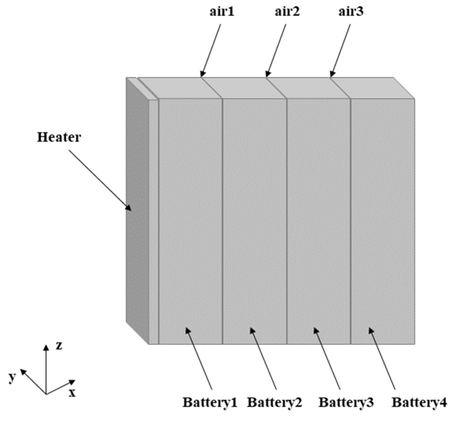
3.1. Geometric Models and Grids

Figure 3 shows the geometric model built according to the actual size of the battery module. The four batteries are labeled as battery 1–4, the cell battery is simplified as a single cell, battery 1 is heated by a heating plate, and batteries 2–4 are affected by the thermal propagation of battery 1. Since no insulation material was added between adjacent cells in the experiment, an air layer was used in the model, and its thickness was set to 2 mm. The model can describe the real module in detail. Table 2 summarizes the physical parameters of each component.

3.2. Mathematical Model

The 3D thermal propagation model is established in ANYSY Fluent. Equation (1) summarizes the energy relation, where ΔE is an increase in battery energy, Qc is the increase in thermal runaway heat of all batteries, and Qt is the heat transfer between the battery module and the environment [28]:
E = Q c + Q t
The 3D thermal runaway propagation model of the battery module satisfies the energy conservation equation [29], as shown in Equation (2):
ρ C p T t = x ( λ x T x ) + y ( λ y T y ) + z ( λ z T z ) + q V
where ρ is the average density of the battery, Cp is the average specific heat capacity of the battery at constant pressure, ∂T/∂t is the temperature change rate of the battery, V is the volume of the battery, qV is the volume calorific value of the battery, and the integration of the cell volume is the heat increase in the cell due to thermal runaway, as shown in Equation (3) [30]:
Q = q V d V
The heat generation Q mainly comes from the chemical side reaction when the battery is experiencing thermal runaway [31,32]. Through an ARC experiment, we obtained the temperature variation law with time when the battery is in thermal runaway. Through a user-defined function, the average temperature of the battery during thermal runaway was obtained by an adjust function, and the heat production of the battery was returned by a source function. The sixth-degree polynomial was used to fit the relationship between them, and the heating rule of a single battery was compiled into Fluent software as the internal heat source for calculation.

3.3. Boundary Conditions

The thermal conductivity of the electric core in this model is anisotropic, that is, λy = λzλx, while the heating plate is isotropic. The related parameter values are shown in Table 1. The third kind of boundary conditions were used for heat transfer with the environment. The convective heat transfer coefficient between the battery module and environment was 5 W·m−2·K−1. The environment temperature was set at 10 °C, which was consistent with the experimental conditions.

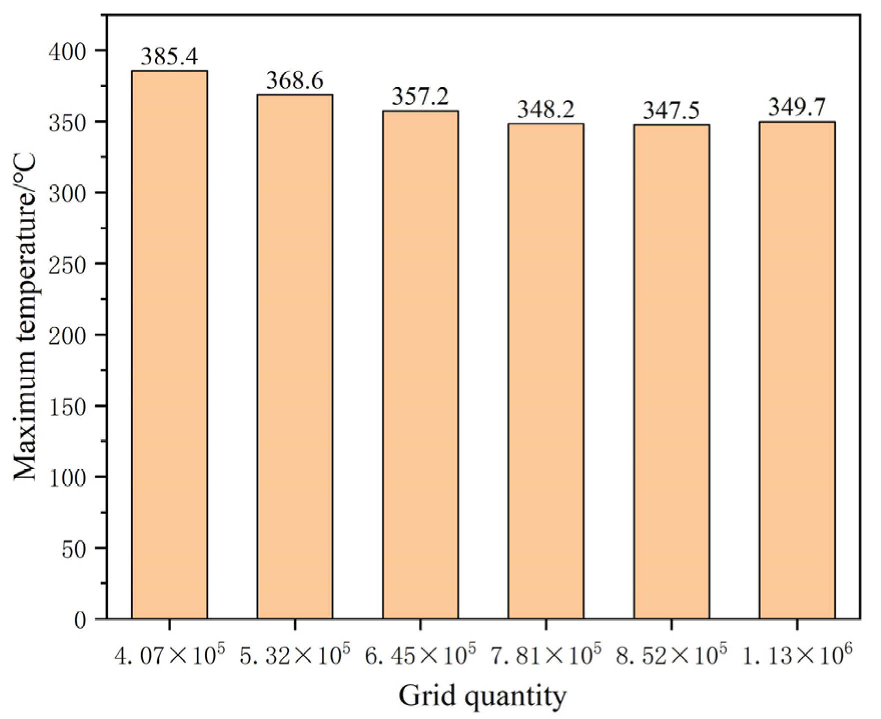
3.4. Grid Division and Independence Verification

The appropriate grid quantity and partition method can not only reduce the computing resources effectively and improve the computing speed, but can also improve the accuracy of the calculation results. Therefore, it is necessary to verify the independence of different numbers of grids. The number of grids ranges from 400,000 to 1.2 million, and 6 kinds of grids were selected for calculation, and the highest temperature of thermocouple No. 3 was taken as the standard of measurement. The maximum temperature corresponding to the number of different grids is shown in Figure 4. When the number of grids is larger than 781,000, the temperature error difference is within 2 °C, which meets the error requirement. Therefore, 781,000 grids were selected in this study to complete the research. The specific grid division results are shown in Figure 5.

4. Results and Discussion

4.1. Model Validation

Since the temperature of the center point of the large surface of a single battery was closest to the average temperature of the battery, thermocouple No. 3, thermocouple No. 7 and thermocouple No. 11 as shown in Figure 2 were selected for comparative verification. Figure 6 shows the comparison of the temperature variation of the three thermocouples between the simulation results and the experiment. The comparison shows that the overall temperature changes are basically the same, and the relative error is about 6.1%, which can verify the validity of the model. The battery average temperature distribution when thermal propagation occurred in the module can be obtained by simulation, as shown in Figure 7. In battery 1, thermal runaway occurred at 2028 s after the start of simulation and reached the highest temperature, which was about 225 °C. Later, due to the convective heat transfer with the environment, and the heat conduction between batteries and insulation materials, the average temperature of battery 1 decreased, while the average temperature of battery 2 kept rising. At 9958 s, battery 2 reached the highest temperature, which was about 358 °C. As can be seen in Figure 7, the time span between battery 1 and battery 2 reaching the maximum temperature was about 7930 s.

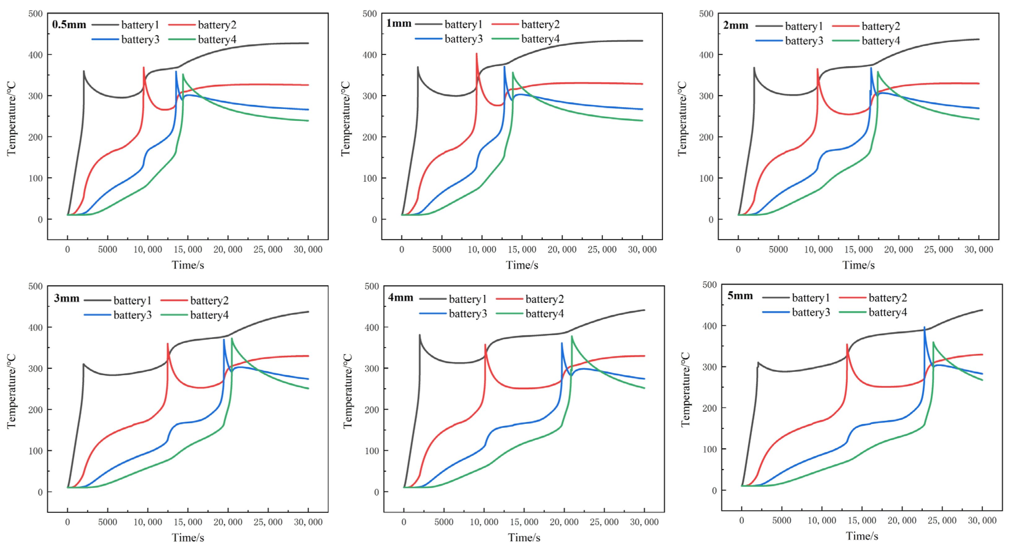
4.2. Thermal Propagation Simulation of Battery Modules with Different Heat Insulation Thickness

In order to analyze the influence of insulation thickness of different adjacent cells on heat transmission, TSAF-0525V organic fireproof coating used in our previous research was selected as the heat insulation material, with thermal conductivity of 0.21 W·m−1·K−1, specific heat of 1500 J·kg−1·K−1 and density of 1420 kg·m−3. Through comparative analysis of the insulation thickness of 0.5 mm, 1 mm, 2 mm, 3 mm, 4 mm and 5 mm, the temperature variation chart of each simulation is shown in Figure 8. It can be concluded from the results that, although increasing the thickness of the heat insulation layer cannot effectively prevent the thermal runaway propagation process, the insulation layer can separate the thermal runaway battery from the adjacent batteries, thereby inhibiting heat transfer between the batteries. The thicker the insulation layer is, the more obvious the inhibition effect is, and the longer the propagation time between the adjacent batteries.
Simulation results show that the complete propagation time (maximum temperature of battery 1 to maximum temperature of battery 4) and the average propagation time of modules with different insulation thickness are shown in Table 3.
With the increase in the thickness of the insulation layer, the propagation time between batteries 1 and 2 and between batteries 2 and 3 increased, but the propagation time between batteries 3 and 4 was less affected by the thickness of the insulation layer. From the analysis of the thickness of each insulation layer, it is obvious that the thermal propagation transfer time of battery 1 to battery 2 was longer than that of battery 2 to battery3 and battery 3 to battery 4, due to thermal runaway in battery 1. The average temperature of batteries 2, 3 and 4 was still relatively low, so the temperature rise of battery 2 was relatively slow. When thermal runaway happened in battery 2, the average temperature of batteries 3 and 4 reached a high level. It can be concluded that when the cell module increases, the thermal propagation time of the late cell is shortened. Therefore, shortening the heat propagation time from battery 1 to battery 2 can effectively delay the thermal runaway propagation process of the whole battery module.
According to the relationship between heat propagation and transfer time of each heat insulation layer thickness, the analysis shows that when the thickness of the insulation layer reaches 2 mm, the total propagation time of thermal runaway is greater than 15,000 s. If the insulation layer is thick, it will not only reduce the energy density of the battery module, but also prevent heat dissipation during the normal operation of the battery module, affecting the heat dissipation performance of the battery module. In addition, it can be seen from the Figure 9 that when the thickness of the insulation layer is 2 mm, the thermal runaway propagation time of batteries 2 and 3 increases significantly, which can validly control the thermal propagation time within a certain range. Therefore, the thickness of 2 mm was selected for the subsequent complex battery module simulation study in this project.

4.3. Thermal Propagation Model of Complex Cell Modules

Based on the existing battery modules, a complex battery pack model was built, and the overall size of the battery pack was 597 mm × 439 mm × 227 mm. Based on the previous single size, a battery module with 1 parallel and 10 series was established. The two rows of the battery modules were distributed side by side with a spacing of 10 mm. The thickness of the insulation layer between adjacent monomers was 2 mm, and the insulation material was TSAF-0525V. The vents on the left and right sides of the battery module were considered in the establishment of the physical model, the size of which was 50 mm × 50 mm. The specific geometric model is shown in Figure 10.
In this model, velocity inlet and pressure outlet were adopted. Considering the air natural convection, 18 solid domains were set up internally, containing 10 battery fields and a thermal insulation layer of eight solid domains, with physical parameter settings as shown in Table 2. An air fluid domain full of incompressible ideal gas was set, and the environment was 25 °C. An internal heat source was added to each cell to describe the heat generation law of thermal runaway.

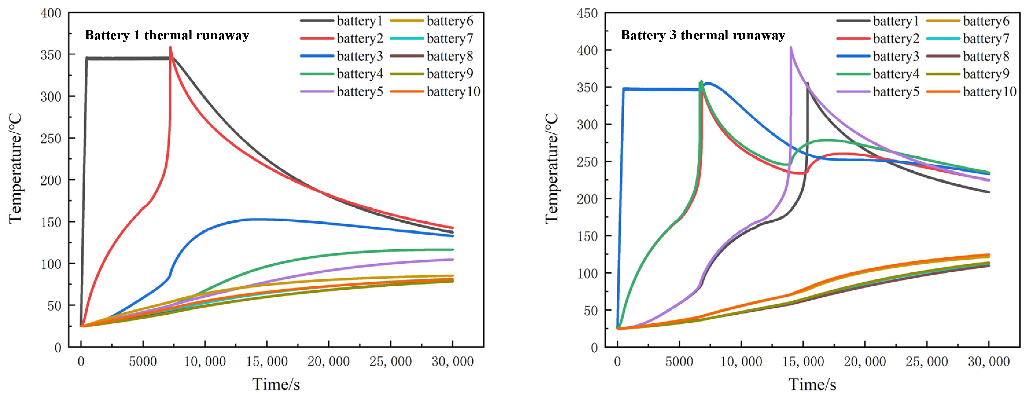
4.4. Single Battery Thermal Runaway

In the simulation, when a single battery is out of control, a UDF (user-defined function) is used to heat the battery to the highest temperature and monitor the temperature changes of other batteries. Figure 11 shows the temperature changes of battery packs after thermal runaway occurs in batteries 1 and 2.
When battery 1 acted as a heater, battery 2 was triggered to thermal runaway, reaching the highest temperature of 339.9 °C, and then entering the cooling stage. As the temperature difference between adjacent battery 2 and battery 3 diminishes, the temperature of battery 3 was not enough to rise to its thermal runaway trigger temperature. Therefore, seen from the simulation results, when battery 1 acts as a heater, it can only lead to thermal runaway of neighboring battery 2 in the x direction, while the temperature of other batteries will only rise to a certain extent.
When battery 3 acted as a heater and thermal runaway occurred, batteries 2 and 4 reached the highest temperature of 356.9 °C almost at the same time around 6800 s. Battery 5 reached a maximum temperature of 403.5 °C at 14,000 s, and battery 1 reached 355.2 °C at 15,350 s. According to the simulation results, no thermal runaway occurred in batteries 6, 7, 8, 9 and 10.

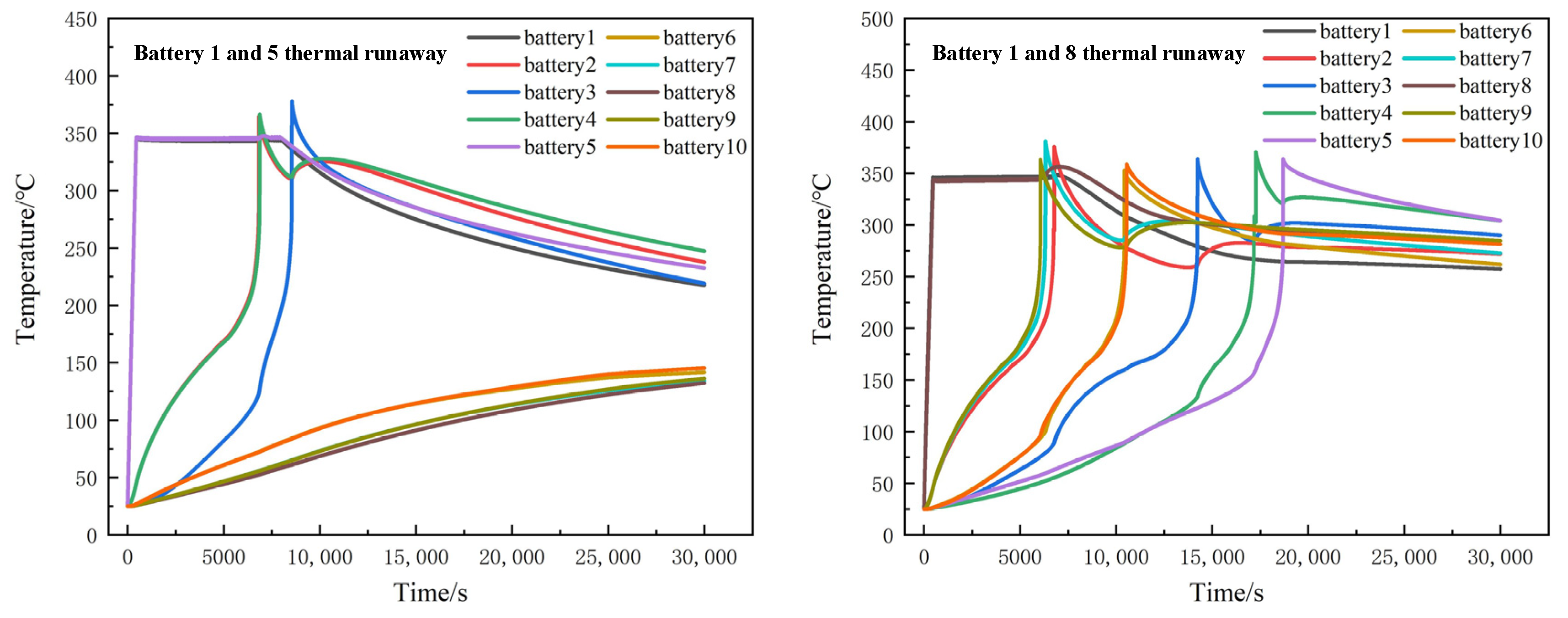
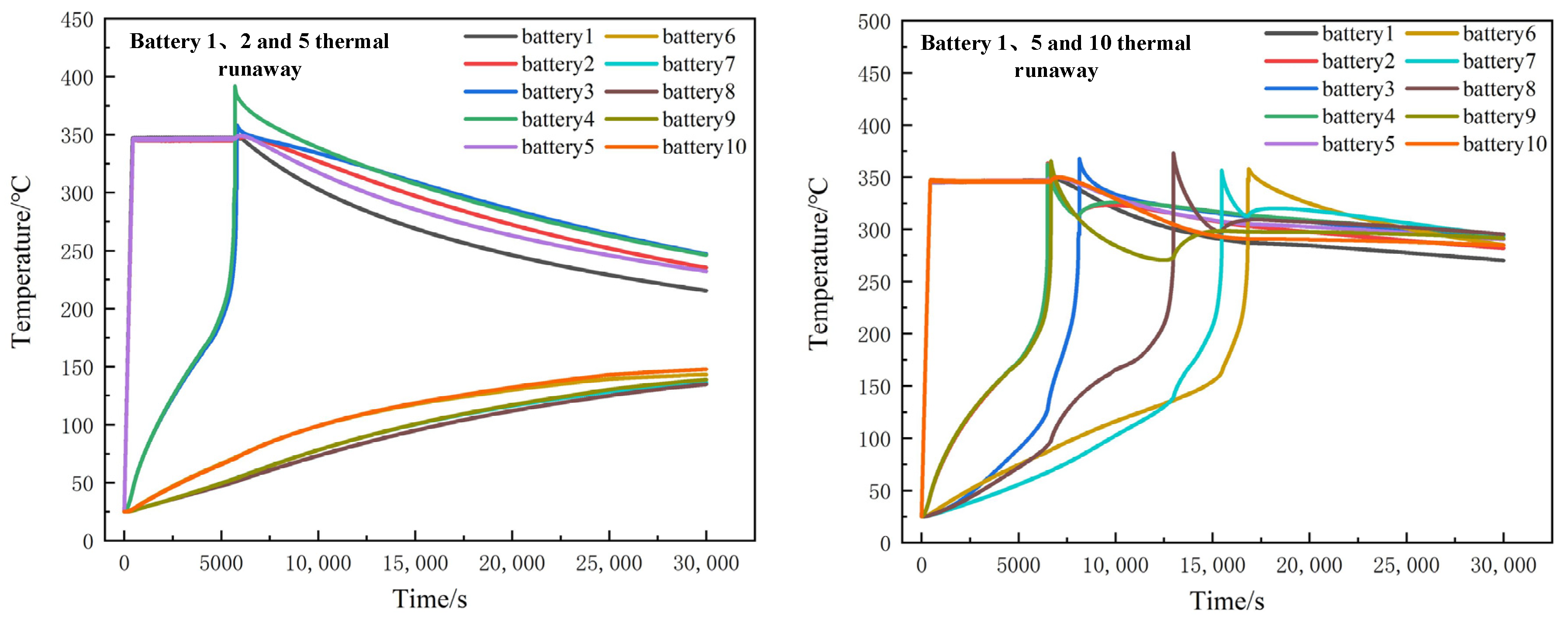
4.5. Multiple Battery Thermal Runaway

When two batteries in the battery module registered thermal runaway, namely batteries 1 and 5, it triggered the thermal runaway of batteries 2 and 4, and then caused thermal runaway of battery 3. Battery 3 reached the highest temperature of 398 °C at 8550 s, while batteries 6 to 10 in the y direction were affected by the thermal runaway of batteries 1 and 5 and registered temperature rise, but not as high as the triggering temperature. When thermal runaway occurred in batteries 1 and 8, thermal runaway would occur in all batteries, and finally in all batteries of the module. The whole process lasted 18,684 s. Batteries 6 and 10 thermal runaway occurred at 10,560 s. The propagation speed of thermal runaway occurring inside the module is faster than that on the edge of the battery module. The temperature change process is shown in Figure 12.
When thermal runaway occurred in three batteries in the battery module, namely in batteries 1, 2 and 5, thermal runaway did not occur in batteries 6 to 10. When thermal runaway occurred in batteries 1, 5 and 10, the thermal runaway speed of the modules would be significantly accelerated. At 16,814 s, thermal runaway happened in all batteries. This is shown in Figure 13.
According to the simulation results, when a battery in a complex battery module experiences thermal runaway, if the distance between two battery modules is 10 mm, the thermal runaway of one battery will cause the temperature of the other battery to rise, but is not likely to trigger thermal runaway. One reason for this is that the thermal conductivity of air is lower than that of thermal insulation. Moreover, less heat is transferred and the spacing between the two adjacent columns is relatively large, so thermal runaway of the battery on the other side is less likely to occur. When thermal runaway occurs on one side of the battery, the battery will eventually develop thermal runaway over time.

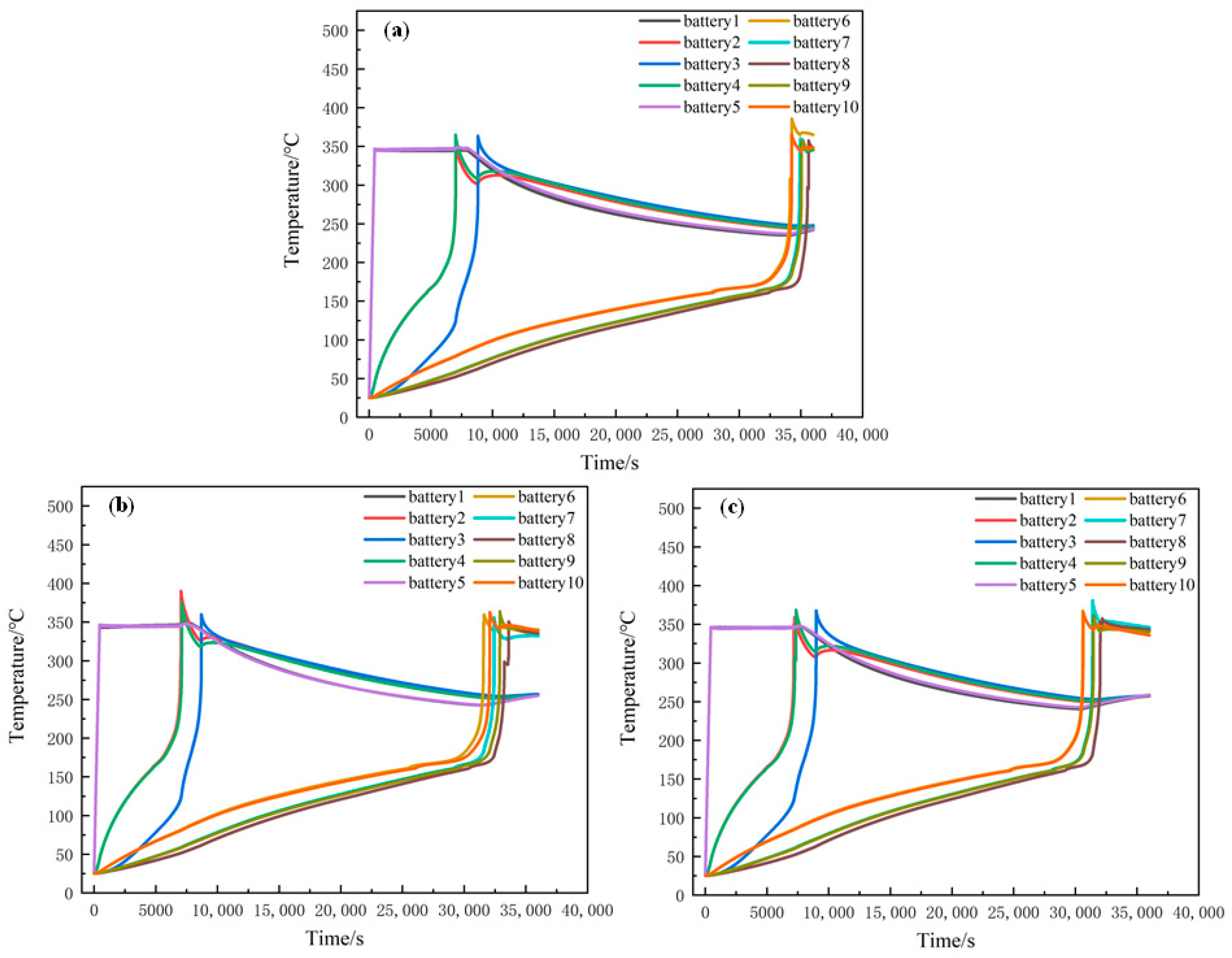
4.6. Thermal Propagation Effect of Different Module Spacing

According to the simulation analysis in the previous section, when the distance between two rows in the battery module is 10 mm, when thermal runaway occurs on one side, the single battery on the other side does not experience thermal runaway within the simulation time of 3000 s. Therefore, in order to explore the influence of spacing on thermal runaway propagation, this section continues to simulate and analyze the temperature changes at 36,000 s when the spacing is 10 mm, 9 mm and 8 mm, respectively, and thermal runaway occurs in batteries 1 and 5.
Figure 14 shows the temperature change in each battery when the thermal runaway of batteries 1 and 5 occurs at the same time and the spacing between the two columns of batteries in the module is 10 mm, 9 mm and 8 mm, respectively. When the spacing is 10 mm, the maximum temperature of batteries 6 and 10 reaches 385.6 °C and 366.1 °C, respectively, at 34,250 s after the thermal runaway of batteries 1 and 5. Batteries 7 and 9 reach the highest temperature at 35,020 s, while battery 8 experiences thermal runaway at 35,636 s. When the interval is 9 mm, the time when the thermal runaway reaches the maximum temperature of battery 10 is 31,566 s in advance. When the interval is 8 mm, the time when thermal runaway reaches the maximum temperature of battery 10 is 29,700 s. This indicates that the smaller the spacing between batteries is, the greater is the possibility of runaway thermal propagation between modules within modules. Therefore, appropriate spacing between battery modules can be designed according to the safety design requirements of energy storage power stations.

5. Conclusions

In this paper, the influence of different insulation thickness of 173 Ah lithium iron phosphate battery on the thermal runaway spread of a simple module and the influence of thermal runaway on the temperature of complex battery modules when different number of batteries experience thermal runaway were studied by experimental and simulation methods. According to the experimental and simulation results, the following conclusions are obtained:
(1)
The large-capacity lithium iron phosphate battery is relatively safe. When the battery is heated to trigger thermal runaway, the maximum temperature of the thermal runaway is about 225 °C at 2000 s after the beginning of the heating. The long interval may be due to the low heating power of the heating plate and the low thermal conductivity of the lithium iron phosphate battery itself.
(2)
Through simulation, increasing the heat insulation layer thickness can delay the heat propagation time of the battery module. Considering the heat insulation layer cost and the energy density of the battery module, this study proposes that the optimal thickness of the insulation layer is 2 mm. If the thickness of the insulation layer is increased, the heat diffusion time will be delayed, but the insulation effect will increase slowly.
(3)
In the complex module, when the distance between the two sides is 10 mm, thermal runaway of the battery on one side will not trigger that of the battery on the other side.

Author Contributions

Conceptualization, Q.B. and K.L.; methodology, K.L. and J.L. (Jian Liu); software, Q.B. and J.L. (Jian Liu); validation, J.L. (Jian Liu); formal analysis, K.L. and J.Z.; investigation, Q.B.; resources, J.Z. and J.O.; data curation, J.O.; writing—original draft preparation, Q.B.; writing—review and editing, J.L. (Jiangyan Liu); visualization, Q.B.; supervision, J.L. (Jiangyan Liu); project administration, J.Z.; funding acquisition, K.L. All authors have read and agreed to the published version of the manuscript.

Funding

This work is supported by the NSF of China (Grant Nos. U20A20310, U1864212 and 52072052), the Fundamental Research Funds for the Central Universities (Grant No. 2021CDJQY-050), National key research and development program (2021YFE0193800) and Guangdong Science and Technology Department (Grant No. 2020B0909030001).

Informed Consent Statement

Our study didn’t involve humans.

Data Availability Statement

We’re not creating new data.

Acknowledgments

We have not received any administrative and technical support, or donations in kind We ensure that all individuals included in this section have consented to the acknowledgement.

Conflicts of Interest

The authors declare no conflict of interest.

Nomenclature

Nomenclature Nomenclature
ρ battery density (kg/m3) Q t heat transfer between battery module and environment (J)
Cpspecific heat capacity (J/(kg K)) E internal energy (J)
Tbattery temperature (°C) q v heat of single battery (W/m3)
ttime (s) T c the increasing rate of temperature (°C/s)
Vcell volume (m3)Abbreviations
λ x , λ y , λ z heat conductivity coefficient in the x, y and z directions (W·m−1·K−1) A R C accelerating rate calorimeter
q h heating plate power (W/m3)SOCstate of charge
Q c thermal runaway heat of battery module (J)3Dthree dimensional
T e environment temperature (°C)

References

  1. Shahid, S.; Agelin-Chaab, M. A review of thermal runaway prevention and mitigation strategies for lithium-ion batteries. Energy Convers. Manag. X 2022, 16, 100310. [Google Scholar] [CrossRef]
  2. Jin, C.; Sun, Y.; Yao, J.; Feng, X.; Lai, X.; Shen, K.; Wang, H.; Rui, X.; Xu, C.; Zheng, Y.; et al. No thermal runaway propagation optimization design of battery arrangement for cell-to-chassis technology. Etransportation 2022, 14, 100199. [Google Scholar] [CrossRef]
  3. Zhang, Q.; Liu, T.; Wang, Q. Experimental study on the influence of different heating methods on thermal runaway of lithium-ion battery. J. Energy Storage 2021, 42, 103063. [Google Scholar] [CrossRef]
  4. Zhou, Z.; Zhou, X.; Li, M.; Cao, B.; Liew, K.; Yang, L. Experimentally exploring prevention of thermal runaway propagation of large-format prismatic lithium-ion battery module. Appl. Energy 2022, 327, 120119. [Google Scholar] [CrossRef]
  5. Jin, C.; Sun, Y.; Wang, H.; Zheng, Y.; Wang, S.; Rui, X.; Xu, C.; Feng, X.; Wang, H.; Ouyang, M. Heating power and heating energy effect on the thermal runaway propagation characteristics of lithium-ion battery module: Experiments and modeling. Appl. Energy 2022, 312, 118760. [Google Scholar] [CrossRef]
  6. Wang, H.; Xu, H.; Zhao, Z.; Wang, Q.; Jin, C.; Li, Y.; Sheng, J.; Li, K.; Du, Z.; Xu, C.; et al. An experimental analysis on thermal runaway and its propagation in cell-to-pack lithium-ion batteries. Appl. Therm. Eng. 2022, 211, 118418. [Google Scholar] [CrossRef]
  7. Chen, J.; Ren, D.; Hsu, H.; Wang, L.; He, X.; Zhang, C.; Feng, X.; Ouyang, M. Investigating the thermal runaway features of lithium-ion batteries using a thermal resistance network model. Appl. Energy 2021, 295, 117038. [Google Scholar] [CrossRef]
  8. Zhai, H.; Chi, M.; Li, J.; Li, D.; Huang, Z.; Jia, Z.; Sun, J.; Wang, Q. Thermal runaway propagation in large format lithium ion battery modules under inclined ceilings. J. Energy Storage 2022, 51, 104477. [Google Scholar] [CrossRef]
  9. Lai, X.; Wang, S.; Wang, H.; Zheng, Y.; Feng, X. Investigation of thermal runaway propagation characteristics of lithium-ion battery modules under different trigger modes. Int. J. Heat Mass Transf. 2021, 171, 121080. [Google Scholar] [CrossRef]
  10. Wang, W.; He, T.; He, S.; You, T.; Khan, F. Modeling of thermal runaway propagation of nmc battery packs after fast charging operation. Process Saf. Environ. Prot. 2021, 154, 104–117. [Google Scholar] [CrossRef]
  11. Li, Z.; Guo, Y.; Zhang, P. Effects of the battery enclosure on the thermal behaviors of lithium-ion battery module during thermal runaway propagation by external-heating. J. Energy Storage 2022, 48, 104002. [Google Scholar] [CrossRef]
  12. Hu, J.; Liu, T.; Tang, Q.; Wang, X. Experimental investigation on thermal runaway propagation in the lithium ion battery modules under charging condition. Appl. Therm. Eng. 2022, 211, 118522. [Google Scholar] [CrossRef]
  13. Wang, Z.; He, T.; Bian, H.; Jiang, F.; Yang, Y. Characteristics of and factors influencing thermal runaway propagation in lithium-ion battery packs. J. Energy Storage 2021, 41, 102956. [Google Scholar] [CrossRef]
  14. Fang, J.; Cai, J.; He, X. Experimental study on the vertical thermal runaway propagation in cylindrical lithium-ion batteries: Effects of spacing and state of charge. Appl. Therm. Eng. 2021, 197, 117399. [Google Scholar] [CrossRef]
  15. Huang, P.; Ping, P.; Li, K.; Chen, H.; Wang, Q.; Wen, J.; Sun, J. Experimental and modeling analysis of thermal runaway propagation over the large format energy storage battery module with Li4Ti5O12 anode. Appl. Energy 2016, 183, 659–673. [Google Scholar] [CrossRef]
  16. Feng, X.; Ren, D.; He, X.; Ouyang, M. Mitigating thermal runaway of lithium-ion batteries. Joule 2020, 4, 743–770. [Google Scholar] [CrossRef]
  17. Li, W.; Wang, H.; Ouyang, M.; Xu, C.; Lu, L.; Feng, X. Theoretical and experimental analysis of the lithium-ion battery thermal runaway process based on the internal combustion engine combustion theory. Energy Convers. Manag. 2019, 185, 211–222. [Google Scholar] [CrossRef]
  18. Shelkea, A.V.; Buston, J.E.H.; Gill, J.; Howard, D.; Williams, R.C.; Read, E.; Abaza, A.; Cooper, B.; Richards, P.; Wen, J.X. Combined numerical and experimental studies of 21700 lithium-ion battery thermal runaway induced by different thermal abuse. Int. J. Heat Mass Transf. 2022, 194, 123099. [Google Scholar] [CrossRef]
  19. Liu, F.; Wang, J.; Yang, N.; Wang, F.; Chen, Y.; Lu, D.; Liu, H.; Du, Q.; Ren, X.; Shi, M. Experimental study on the alleviation of thermal runaway propagation from an overcharged lithium-ion battery module using different thermal insulation layers. Energy 2022, 257, 124768. [Google Scholar] [CrossRef]
  20. Niu, H.; Chen, C.; Liu, Y.; Li, L.; Li, Z.; Ji, D.; Huang, X. Mitigating thermal runaway propagation of ncm 811 prismatic batteries via hollow glass microspheres plates. Process Saf. Environ. Prot. 2022, 162, 672–683. [Google Scholar] [CrossRef]
  21. Song, L.; Huang, Z.; Mei, W.; Jia, Z.; Yu, Y.; Wang, Q.; Jin, K. Thermal runaway propagation behavior and energy flow distribution analysis of 280 ah lifepo4 battery. Process Saf. Environ. Prot. 2023, 170, 1066–1078. [Google Scholar] [CrossRef]
  22. Rui, X.; Feng, X.; Wang, H.; Yang, H.; Zhang, Y.; Wan, M.; Wei, Y.; Ouyang, M. Synergistic effect of insulation and liquid cooling on mitigating the thermal runaway propagation in lithium-ion battery module. Appl. Therm. Eng. 2021, 199, 117521. [Google Scholar] [CrossRef]
  23. Liu, Q.; Zhu, Q.; Zhu, W.; Yi, X. Study on the blocking effect of aerogel felt thickness on thermal runaway propagation of lithium-ion batteries. Fire Technol. 2023, 59, 381–399. [Google Scholar] [CrossRef]
  24. He, X.; Zhao, C.; Hu, Z.; Restuccia, F.; Richter, F.; Wang, Q.; Rein, G. Heat transfer effects on accelerating rate calorimetry of the thermal runaway of lithium-ion batteries. Process Saf. Environ. Prot. 2022, 162, 684–693. [Google Scholar] [CrossRef]
  25. Zhao, C.; Sun, J.; Wang, Q. Thermal runaway hazards investigation on 18650 lithium-ion battery using extended volume accelerating rate calorimeter. J. Energy Storage 2020, 28, 101232. [Google Scholar] [CrossRef]
  26. Son, K.; Hwang, S.M.; Woo, S.-G.; Koo, J.K.; Paik, M.; Song, E.H.; Kim, Y.-J. Comparative study of thermal runaway and cell failure of lab-scale li-ion batteries using accelerating rate calorimetry. J. Ind. Eng. Chem. 2020, 83, 247–251. [Google Scholar] [CrossRef]
  27. Huang, X.; Xiao, M.; Han, D.; Xue, J.; Wang, S.; Meng, Y. Thermal runaway features of lithium sulfur pouch cells at various states of charge evaluated by extended volume-accelerating rate calorimetry. J. Power Sources 2021, 489, 229503. [Google Scholar] [CrossRef]
  28. Hong, J.; Wang, Z.; Qu, C.; Wen, J. Investigation on overcharge-caused thermal runaway of lithium-ion batteries in real-world electric vehicles. Appl. Energy 2022, 321, 119229. [Google Scholar] [CrossRef]
  29. Kong, D.; Wang, G.; Ping, P.; Xu, J. Numerical investigation of thermal runaway behavior of lithium-ion batteries with different battery materials and heating conditions. Appl. Therm. Eng. 2021, 189, 116661. [Google Scholar] [CrossRef]
  30. Jia, Y.; Uddin, M.; Li, Y.; Xu, J. Thermal runaway propagation behavior within 18,650 lithium-ion battery packs: A modeling study. J. Energy Storage 2020, 31, 101668. [Google Scholar] [CrossRef]
  31. Chen, J.; Rui, X.; Hsu, H.; Lu, L.; Zhang, C.; Ren, D.; Wang, L.; He, X.; Feng, X.; Ouyang, M. Thermal runaway modeling of lini0.6mn0.2co0.2o2/graphite batteries under different states of charge. J. Energy Storage 2022, 49, 104090. [Google Scholar] [CrossRef]
  32. Wang, L.; Ouyang, M. Thermal runaway modeling of large format high-nickel/silicon-graphite lithium-ion batteries based on reaction sequence and kinetics. Appl. Energy 2022, 306, 117943. [Google Scholar] [CrossRef]
Figure 1. Photo of adiabatic accelerated calorimeter.
Processes 11 01321 g001
Figure 2. System diagram of thermal propagation experiment.
Processes 11 01321 g002
Figure 3. Geometric model of battery module.
Processes 11 01321 g003
Figure 4. Maximum temperature diagram of thermocouple 3 corresponding to different grid numbers.
Processes 11 01321 g004
Figure 5. Study grid division diagram.
Processes 11 01321 g005
Figure 6. Comparison of experimental and simulation results of three thermocouples.
Processes 11 01321 g006
Figure 7. Simulation results of battery module.
Processes 11 01321 g007
Figure 8. Average temperature variation of cells with different heat insulation thicknesses.
Processes 11 01321 g008
Figure 9. Relationship between heat propagation and transfer time of each insulation layer thickness.
Processes 11 01321 g009
Figure 10. Physical model of battery pack.
Processes 11 01321 g010
Figure 11. Thermal runaway temperature distribution of a single battery.
Processes 11 01321 g011
Figure 12. Temperature distribution of two batteries during thermal runaway.
Processes 11 01321 g012
Figure 13. Temperature distribution of three batteries when thermal runaway occurs.
Processes 11 01321 g013
Figure 14. The influence of different spacing on thermal runaway propagation: (a) 10 mm; (b) 9 mm; (c) 8 mm.
Processes 11 01321 g014
Table 1. Information about the experimental battery.
SpecificationInformation
Mass (kg)3.25
Anode materialGraphite (purity 99.5%)
Cathode materialLiFePO4
Size (mm)41 × 174 × 207
Rated capacity (Ah)173
Rated voltage (V)3.2
Cut-off voltage (V)3.65
The SOC of module0.5
Table 2. Physical parameters of each component.
ComponentCalorific Value (W/m3)Cp (J·kg−1·K−1)ρ (kg·m−3)λ (W·m−1·K−1)
Battery10602125.8λx = 1.6, λy = 18.034, λz = 18.034
Heater960328088034.8
Air layer1006.431.1690.0242
Table 3. Comparison of propagation time with different insulation layer thicknesses.
Insulation Layer Thickness/mmComplete Propagation Time/sAverage Propagation Time/s
0.511,8463948.7
112,3664122
215,3965132
318,4966165.3
418,9746324.7
521,8427280.7
Disclaimer/Publisher’s Note: The statements, opinions and data contained in all publications are solely those of the individual author(s) and contributor(s) and not of MDPI and/or the editor(s). MDPI and/or the editor(s) disclaim responsibility for any injury to people or property resulting from any ideas, methods, instructions or products referred to in the content.

