Article

A Casing Deformation Prediction Model Considering the Properties of Cement

1
Shale Gas Research Institute, PetroChina Southwest Oil and Gasfield Company, Chengdu 610051, China
2
State Key Laboratory for Performance and Structure Safety of Petroleum Tubular Goods and Equipment Materials, CNPC Tubular Goods Research Institute, Xi’an 710077, China
3
Development Department, PetroChina Southwest Oil and Gas Field Company, Chengdu 610051, China
4
Engineering Technology Division, PetroChina Southwest Oil and Gas Field Company, Chengdu 610051, China
5
Sichuan Shale Gas Exploration and Development Co., Ltd., Neijiang 641000, China
*
Authors to whom correspondence should be addressed.
Processes 2023, 11(3), 695; https://doi.org/10.3390/pr11030695
Submission received: 4 November 2022 / Revised: 16 December 2022 / Accepted: 23 February 2023 / Published: 24 February 2023
(This article belongs to the Special Issue Risk Assessment and Reliability Engineering of Process Operations)

Abstract

:
A large amount of casing deformation has occurred in shale gas wells during the complex fracturing process, which affects the fracturing construction and single well production. Based on the statistical analysis of casing deformation wells and caliper logging interpretation, the main mechanism of casing deformation of shale gas wells is revealed as formation slip. By comprehensively considering the rotating speed under casing running condition, the cement solidification heat release under cementing condition, and the fracturing fluid temperature drop under fracturing condition, the safe service margin of the casing is large. Moreover, simply increasing the casing steel grade and wall thickness has no obvious effect on casing deformation prevention, so full wellbore casing deformation prevention measures should be considered. By using the method of unconventional oil and gas well casing string simulation test and numerical simulation, the mechanical response of wellbore and the mechanism of bridge plug resistance are analyzed. By analyzing the influence of elastic modulus and wall thickness of cement on the casing minimum drift diameter after shear deformation, an analytical model of the minimum drift diameter of shale gas casing under the effect of fracture slip is established and verified, which provides technical support for parameter selection of cement and measures to prevent casing deformation.

1. Introduction

With the rapid development of shale gas exploration in China, casing deformation of shale gas horizontal wells occurs frequently, which directly affects the efficiency and benefits of shale gas development [1,2]. By August 2022, 98 casing deformation wells have been found in the shale gas development of Luzhou Block in Southwest China, including 31 wells without fracturing and 67 wells deformed during fracturing. In the 31 wells without fracturing, the remaining casing drift diameter of more than 85 mm can be normally modified with a bridge plug of small diameter, for a total of seven wells. Four wells with the remaining drift diameter of 54–85 mm can be combined. The other twenty casing deformation wells with drift diameter of less than 54 mm can not be perforated. Therefore, preventing and controlling casing deformation is very critical and urgent during shale gas development.
At present, prevention and control of casing deformation mainly considers the casing strength and wall thickness [3]. Domestic and foreign experts and scholars have studied the deformation characteristics of high grade steel casing under non-uniform external extrusion and shear loads using the finite element method, and also analyzed the influencing factors [4,5,6,7]. The casing wall thickness is another important parameter. When the casing wall thickness increases, the shear strength, collapse strength, tensile strength and internal pressure resistance increase greatly. Landry et al. believed that the casing string deformation of staged fracturing in shale gas horizontal wells was caused by formation shear slip, using the method of numerical simulation and log information analysis [8]. For high steel grade (≥758.4 MPa) casings, increasing the casing wall thickness was more effective than steel grade for improving the shear resistance. However, under the condition of formation slip, the casing deformation prevention effect is still not obvious by improving the casing anti extrusion strength and wall thickness. Consequently, it is necessary to consider the coordinated prevention and control method of the whole wellbore.
In terms of cement performance, Wang et al. established mechanical models of casing, cement sheath, and formation [9], and analyzed the influence of geometric and physical parameters of cement on the casing load. The results showed that the increase in cement Young’s modulus led first to the increase in casing load and then to a decrease. With the increase in Poisson’s ratio, the loads of cement and casing both increased. Qu et al. have established an analytical model for the casing load considering the cement and formation. The casing load and stress distribution with non-uniform stress could be analyzed [10]. Therefore, the current research mainly focuses on the casing load considering cement performance. The influence law and model of cement performance on casing displacement need to be studied urgently.

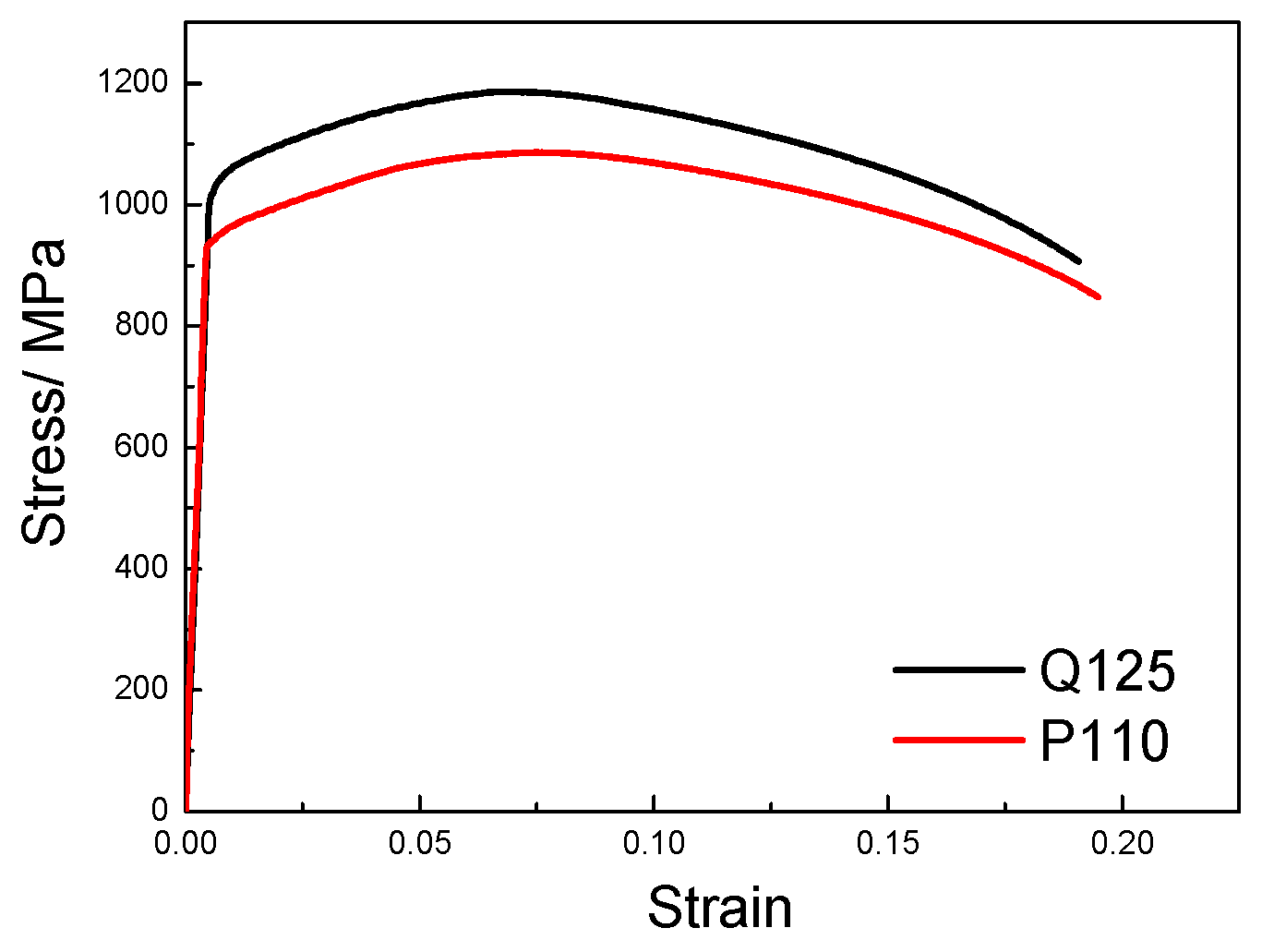
2. Materials and Methods

The casing materials studied in this paper are P110 and Q125 steels, and the sizes are φ127 × 11.1 mm and φ139.7 × 12.7 mm, respectively. The yield strength of P110 is 935.3 MPa, and the yield strength of Q125 is 1014.9 MPa. The true stress and strain curves of P110 and Q125 are shown in Figure 1. In this paper, the method of combining full size test and finite element simulation was used to study the deformation of casing–cement sheath under the action of non-uniform external extrusion and shear, and the load and minimum drift diameter were analyzed. Based on ABAQUS 6.11 software, sourced from CNPC Tubular Goods Re-search Institute, Xi’an, China, P110 (φ127 × 11.1 mm) and Q125 (φ139.7 × 12.7 mm) casing shear deformation were conducted by finite-element simulation. Both ends of the cement sheath and casing were fixed, which was consistent with the actual downhole working conditions. Due to the symmetry of the model, one half of the whole model was taken as the calculation model in this paper. Under the condition of formation slip, the minimum drift diameter of the casing–cement sheath system under the action of shear force could be calculated. The influence of the friction coefficient on the minimum drift diameter has been studied, and the effect was very small. In addition, in the actual shear tests, the load–displacement curves under different lubrication conditions showed little change, and this was consistent with the simulation results. Therefore, the friction coefficient was set to the conventional 0.2. For the casing, the Von Mises yielding criterion and isotropic hardening law were adopted.

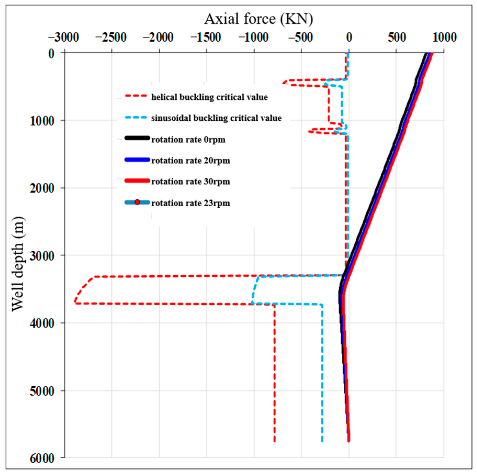
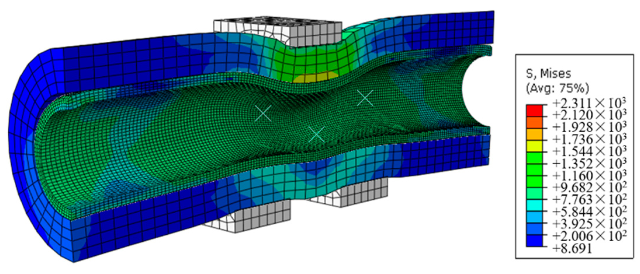
3. Casing Deformation Mechanism and Boundary Conditions of Shale Gas Wells

A large amount of casing deformation occurs in the complex fracturing process of shale gas wells, which adversely affects the fracturing operation of shale gas wells and the productivity of single wells. First of all, based on the strength theory, the use safety of the casing is analyzed. Under the casing running condition, when the rotating speed is 20~30 rpm, it can eliminate buckling deformation of casing under inertia casing mode; also, the axial force on the casing meets the strength requirements, as shown in Figure 2. In the process of cementing, cement hydration exothermic heat leads to an increase in temperature, and the exothermic temperature under different well depths is calculated numerically to be less than or equal to 15 °C, as shown in Figure 3. Under fracturing condition, considering the wellbore temperature alternation caused by fracturing fluid, the temperature drop values are calculated by numerical method, which is less than or equal to 67 °C. Considering the above three working conditions in the whole process of cementing fracturing, the safe service margin of the casing is large, so the strength of the casing can fully meet the operating requirements.
Based on the statistical analysis of casing deformation wells and caliper logging interpretation, the morphological characteristics of casing deformation can be obtained, and the main controlling factors of casing deformation in deep shale gas wells are revealed, which can provide a research basis for deformation prevention. Figure 4 shows a typical casing deformation logging morphology, indicating that uneven extrusion deformation occurs in many segments, while shear morphology is shown in the transition zone between deformation and non-deformation or extrusion deformation [11,12]. In addition, during multi-stage fracturing, it is easy to cause the activation of faults, leading to local formation slip, which causes the casing to bear huge shear loads and deformation [13]. As shown in Figure 5, the casing deformation locations are mainly concentrated in the horizontal section (close to point A), and the coincidence rate between casing deformation locations and faults/fractures is high. For example, the coincidence rate between casing deformation locations and faults/fractures of four wells in the Luzhou 203H4 platform exceeds 80%. Therefore, according to the logging data and analysis of complex fracturing casing deformation in shale gas wells, it is determined that the casing deformation modes are mainly non-uniform extrusion dominated, shear dominated, or the composite morphology, and it is determined that the main controlling factor of casing deformation in deep shale gas wells is formation slip.
Figure 6 shows the verification results of production casing string, for the casing of Q125, φ139.7 × 12.7 mm, the anti-collapse coefficient, anti-internal pressure coefficient, tensile coefficient, and triaxial coefficient of the casing are greater than the design safety coefficient, meeting the strength requirements of the casing. When the casing steel grade is increased from Q125 to 140 V, the safety coefficient of the casing is greatly increased, and the anti-collapse coefficient reaches about 2.0, which is far greater than the design one, but the effect of increasing the steel grade to prevent casing deformation is not obvious. For the casing body, when the wall thickness increases from 12.7 mm to 15.2 mm, the statistical results of engineering test wells show that the casing deformation rate is also more than 50%. Therefore, simply increasing casing steel grade and wall thickness have no obvious effect on casing deformation prevention in deep shale gas horizontal wells, so it is necessary to consider casing deformation prevention measures for the whole wellbore.
According to the statistics of casing deformation in Weiyuan Block, Sichuan, the proportion of deformation less than or equal to 30 mm is more than 80%, and the corresponding formation slip is less than or equal to 40 mm through laboratory tests and numerical simulation inversion. This is the boundary condition of the whole wellbore optimization design determined in this paper.

4. Protective Effect and Influence Law of Cement Sheath on Casing

Under large formation slip, casing deformation occurs due to shearing or non-uniform extrusion, which seriously affects the running and trafficability of bridge plug tools. As shown in Figure 7, due to fault slip, the bridge plug diameter changes from D to (D-d1-d2). Therefore, it is necessary to study the minimum diameter of the casing cement sheath after deformation.

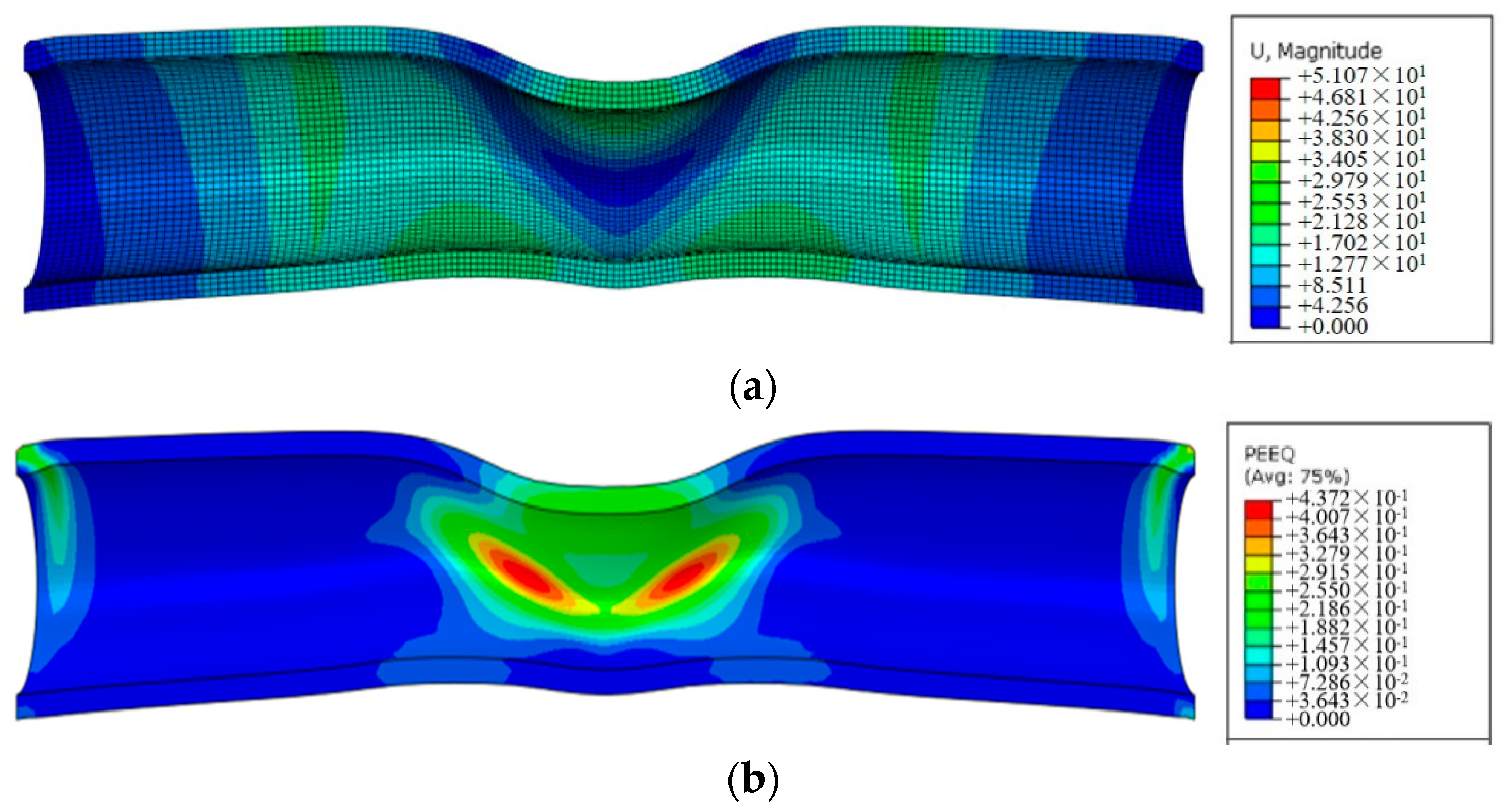
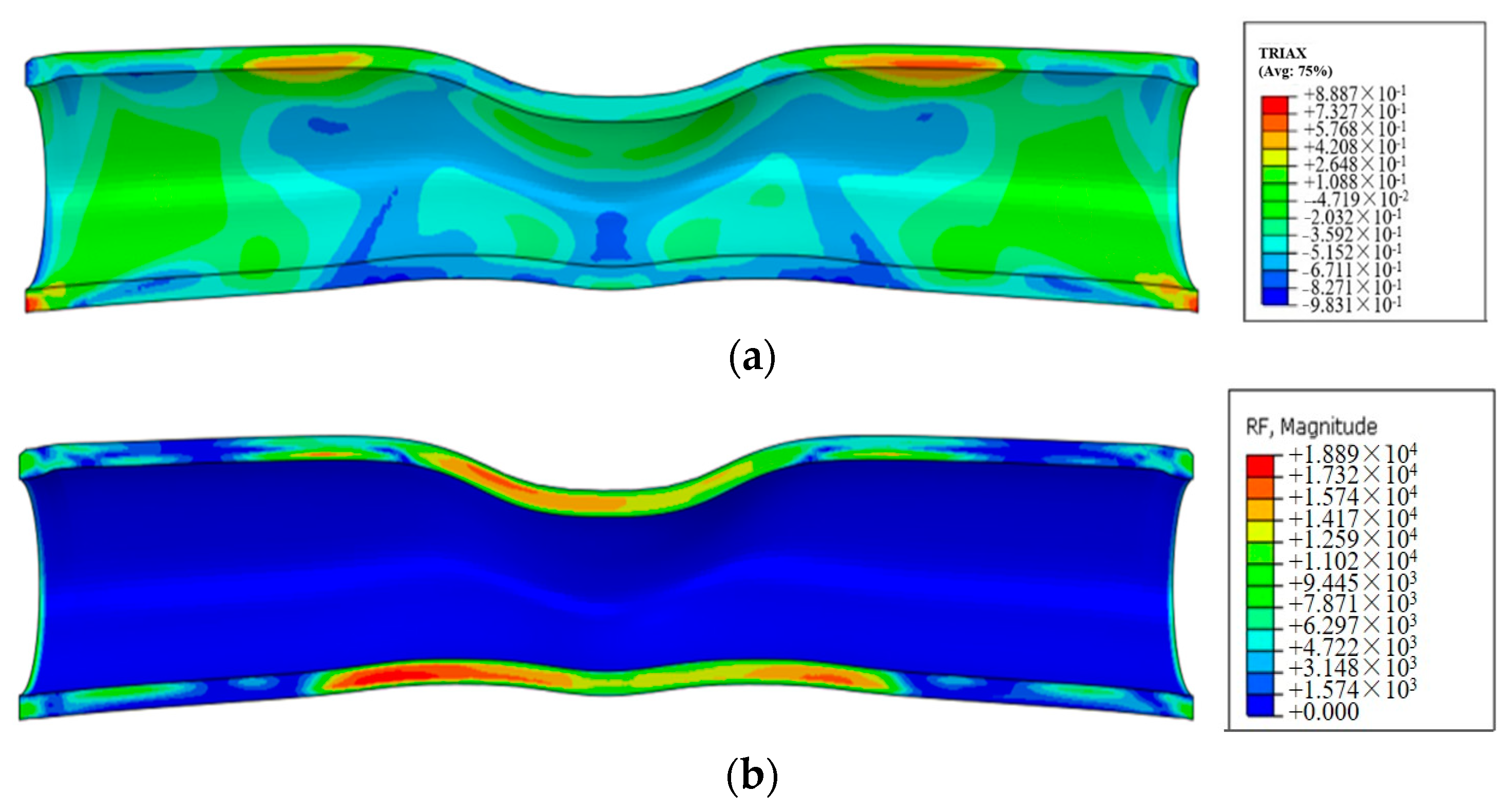
4.1. Protective Effect of Cement Sheath on Casing

Shear tests are conducted on Q125 (φ139.7 × 12.7 mm) casing. For the 800 mm long Q125 casing, the “unconventional oil and gas well casing string simulation test system” is used for the shear test. A Vernier caliper is used to measure the diameter in the pressure direction and vertical direction at 1/2 position of the pipe body, and an ultrasonic thickness gauge is used to measure the wall thickness of four points evenly distributed on the circular ring of the cross section. The maximum shear load after 40 mm shear is 2850 KN. The casing morphology after the shear test is shown in Figure 8. Figure 8a is the indoor test equipment diagram, Figure 8b is the tube blank diagram after 40 mm shear deformation; the minimum diameter after the test measured by Vernier caliper is 109.74 mm, and the corresponding pipe inner diameter is 83.34 mm (i.e., Section AB in Figure 8c, 109.74 − 12.7 × 2 = 84.34 mm). Since the minimum diameter can not be directly measured in the test, the method of combining the test with numerical simulation is adopted here. Figure 8c shows the cloud diagram of equivalent stress distribution for finite element simulation of the pipe body after 40 mm shear deformation; where the casing ends are fixed, half of the model is calculated due to structural symmetry, and the hexahedral grids are used. For the casing, the Von Mises yielding criterion and isotropic hardening law are adopted. Then the minimum diameter is calculated, that is, the radial distance AB from the top to the bottom of the upper shear fixture, minus the radial distance BC from the bottom to the top of the lower shear fixture; the minimum diameter is 80.51 mm (85.89 − 5.38 = 80.51 mm), and the deformation is 33.79 mm. Comparing the length value of the AB section in the test and simulation, the error is 1.8% ((85.89 − 84.34)/84.34 × 100% = 1.8%), which proves the reliability of the finite element model. Using the method of combining test with numerical simulation, the minimum path under different test parameters can be calculated, providing data support for the analytical model of bridge plug trafficability.
From the analysis of the test results, the outer diameter of Q125 (φ139.7 × 12.7) casing decreases due to the 40 mm shearing force. Through measurement, it is found that the minimum outer diameter of the casing after shearing is 118.04 mm, the deformation value is 18.66 mm, and the deformation amount is 13.36%. The maximum load imposed by the shear test is 2061 KN. The finite element model is established for the casing and cement sheath; the length and thickness of the cement sheath is 800 mm and 38.1 mm, the elastic modulus is 9 GPa after 40 mm shearing of the casing–cement sheath system. The Mises stress is shown in Figure 9c; compared with the casing pipe shear deformation, the equivalent stress after adding the cement sheath is significantly reduced, and the minimum diameter calculated by the same method is 82.08 mm (87.1 − 5.02 = 82.08 mm). The error of the AB section length value in comparison with the test and simulation is 5.98% ((92.64 − 87.1)/92.64 × 100% = 5.98%), which proves the reliability of the casing–cement sheath finite element model. The minimum diameter of the casing–cement sheath system after the shear test is 82.08 mm, which is 1.57 mm larger than the minimum diameter of the pure pipe 80.51 mm, and the deformation of the minimum diameter is 1.95% smaller. At the same time, the shear load is 13.53% smaller. Therefore, the elastic cement sheath plays a certain role in casing deformation, and it is necessary to carry out casing deformation research under different cement sheath parameters.

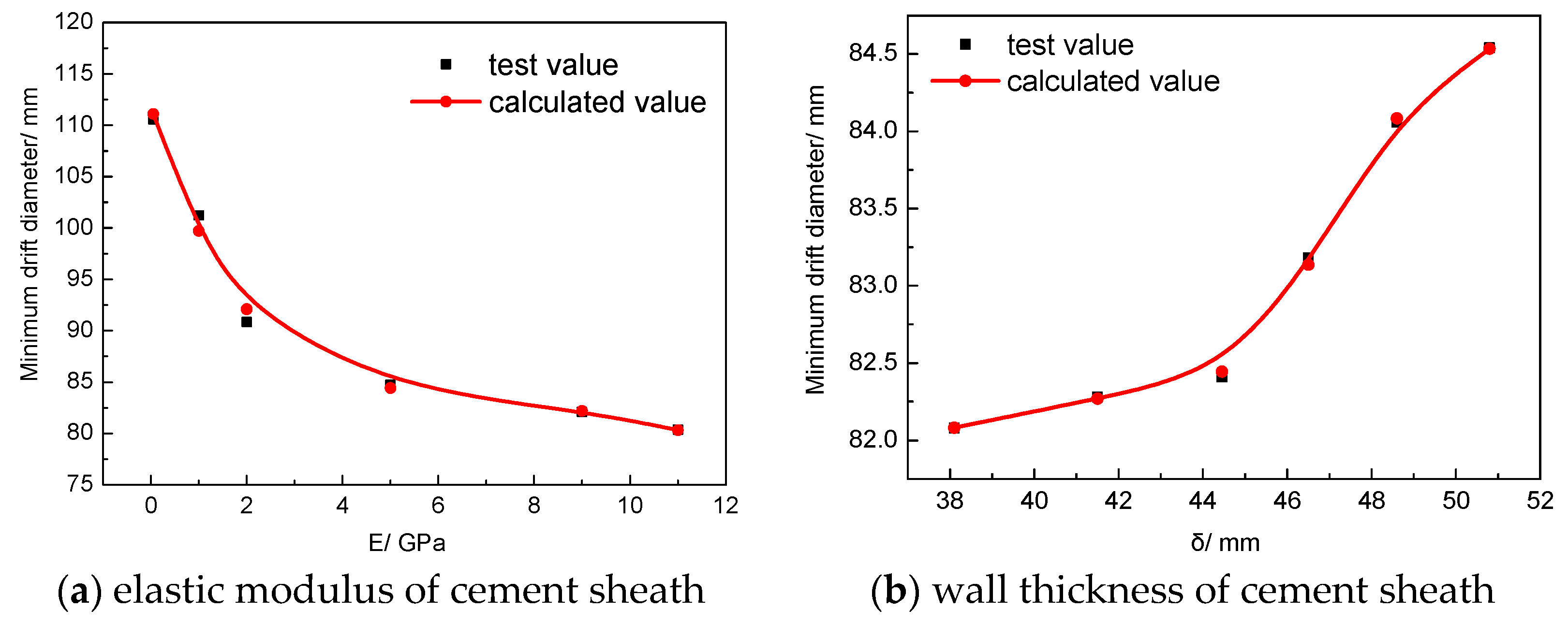
4.2. Influence of Elastic Modulus of Cement Sheath on Casing Deformation

The cement sheath is an important part of wellbore, which is used to support the casing and isolate annulus fluid. Moreover, the cement sheath is the transition zone between the formation and casing string, which acts as a medium to transfer the formation load and displacement to the casing. In order to clarify the influence of the cement sheath performance on the casing stress and the minimum diameter under the action of formation slip, the wall thickness of the cement sheath is 38.1 mm, and the elastic modulus of the cement sheath is 0.05, 2, 5, 9 and 11 GPa, respectively. The casing deformations under different elastic modulus are simulated, and the influence law of the cement elastic modulus on casing deformation is obtained.
The radial length of section AB of Figure 8c is H1, the radial length of section BC is H2, the minimum drift diameter is Hmin, and the deformation of minimum drift diameter is ΔH. When the elastic modulus is 11 GPa, H1 is 85.84 mm, H2 is 5.48 mm, and Hmin is 80.36 mm. The deformation of minimum drift diameter ΔH is 33.94 mm.
When the elastic modulus is 9 GPa, H1 is 86.84 mm, H2 is 4.76 mm, and Hmin is 82.08 mm. The deformation of minimum drift diameter ΔH is 32.22 mm. The displacement distribution after 40 mm shearing is as shown in Figure 10a. Due to the protective effect of the cement sheath, the displacement of the casing part in contact with upper die is about 18 mm. The maximum equivalent plastic strain of the casing is located at the transition zone of the upper and lower molds, and the maximum value is 0.44 (Figure 10b). After 40 mm shearing deformation, the stress triaxiality of the casing is as shown in Figure 11a. The casing parts contacting the upper and lower dies are compressive stress, and the stress triaxiality at the lower die is the minimum, −0.98. The maximum stress triaxiality is located near the upper die. The casing arches upward in the tensile stress state, and the stress triaxiality is 0.89. The load distribution is shown in Figure 11b; the casing contacting the upper and lower shear dies is subjected to the maximum load of 1889 KN.
When the elastic modulus of cement sheath is 5 GPa, H1 is 88.96 mm, H2 is 4.22 mm, and Hmin is 84.74 mm. The deformation of minimum drift diameter ΔH is 29.56 mm. When the elastic modulus of the cement sheath is 2 GPa, H1 is 93.65 mm, H2 is 2.81 mm, and Hmin is 90.84 mm. The deformation of minimum drift diameter ΔH is reduced to 23.46 mm.
When the elastic modulus of the cement sheath is 1 GPa, H1 is 103.18 mm, H2 is 1.95 mm, and Hmin is 101.23 mm. The deformation of minimum drift diameter ΔH is 3.72 mm. When the elastic modulus of the cement sheath is 0.05 GPa, H1 is 111.94 mm, H2 is 1.36 mm, Hmin is 110.58 mm, and the deformation of minimum drift diameter ΔH is 3.72 mm, the deformation rate is only 3.25%, but an elastic modulus that is too low is difficult to achieve in engineering applications.
In conclusion, when the elastic modulus of cement decreases, the deformation of the casing gradually decreases and the minimum drift diameter increases. When the elastic modulus of the cement slurry is less than or equal to 2 GPa, the deformation of the casing is reduced greatly. In order to ensure the smooth passage of bridge plugs and other tools in the casing, the elastic modulus of the cement is recommended to be less than 2 GPa, that is, using super flexible cementing materials or even not cementing. Even if the fault slip distance is large, the casing would not have excessive deformation. This is because the cementing material, acting as the force transmission medium between the casing and formation, could replace the casing to “absorb” the deformation. The lower the elastic modulus, the stronger the “absorption” effect.

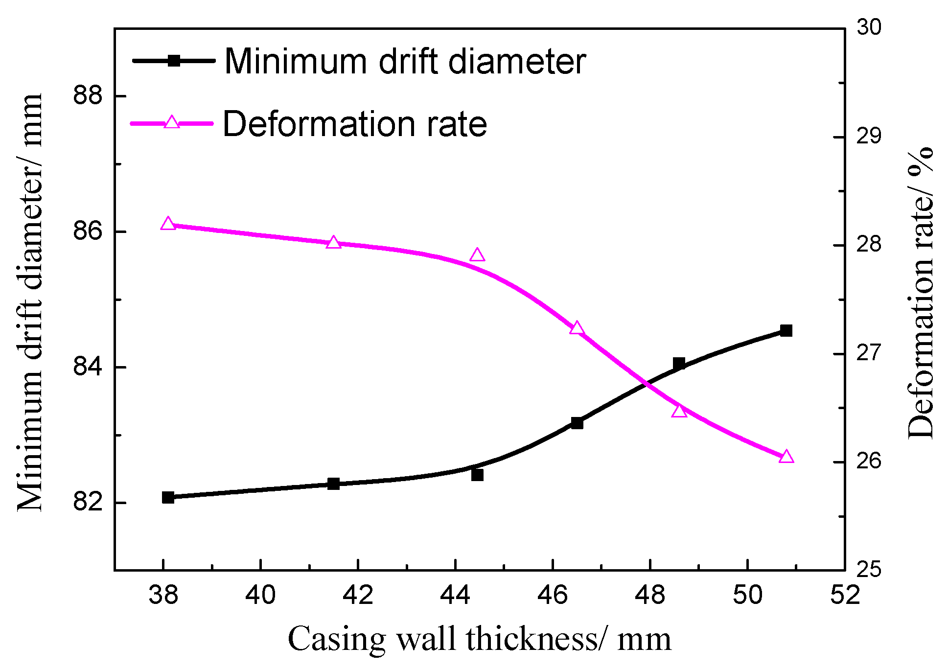
4.3. Influence of Cement Sheath Wall Thickness on Casing Deformation

From the analysis in Section 4.2, the cement can play the role of “absorbing” deformation, so it is speculated that the method of expanding the cement diameter is feasible. When the elastic modulus of cement is set as 9 GPa, the wall thicknesses of the cement sheath are 50.80 mm, 48.60 mm, 46.50 mm, 44.45 mm, 41.50 mm and 38.10 mm, respectively, and the minimum drift diameters of the casing after 40 mm shearing deformation are obtained through finite element simulation.
When the wall thickness of the cement sheath is 50.8 mm, H1 is 87.7 mm, H2 is 3.16 mm, and Hmin is 84.54 mm. The deformation of minimum drift diameter ΔH is 29.76 mm. The equivalent stress distribution of the casing–cement sheath after 40 mm shearing is shown in Figure 12. It can be seen that increasing the thickness of cement sheath can greatly reduce the casing stress, and the minimum drift diameter of the casing increases to ensure the smooth passage of bridge plugs or other tools. When the thickness of the cement sheath increases from 38.1 mm to 50.8 mm, the maximum load value of the upper mold increases from 2061 KN to 2830 KN. However, due to the protection of the cement part, the equivalent stress of the casing decreases by 50 MPa, indicating that the thicker cement sheath can significantly reduce the stress on the casing.
When the wall thickness of the cement sheath is changed from 48.6 mm to 38.1 mm, H1, H2, Hmin and ΔH values are shown in Table 1. With the decrease in wall thickness, the casing deformation degree increases, and H1 decreases gradually while H2 increases. The influence of the elastic cement sheath thickness on the minimum diameter of the casing is shown in Figure 13. With the increase in the cement sheath thickness, the minimum diameter of the casing increases, and the casing deformation rate decreases from 28.19% to 26.04%.

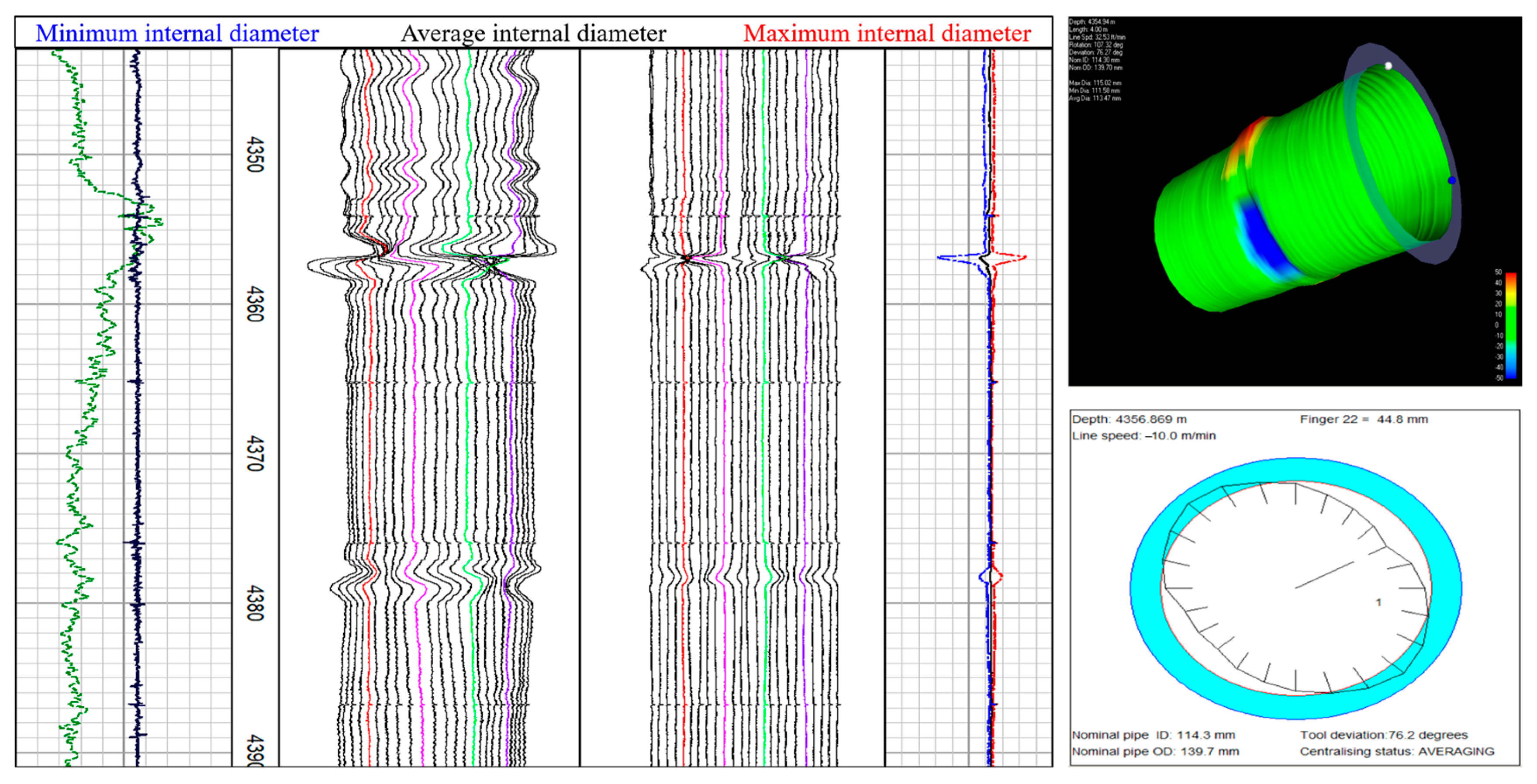
5. Establishment and Verification of Prediction Model for Casing Minimum Drift Diameter

The downhole cement sheath is located between the casing and the surrounding rock of the outer wall. The inner wall bears the force of the casing and the outer wall bears the pressure of the surrounding rock. After the cement slurry solidification, the casing, cement sheath and wall rock will be consolidated into a composite elastomer. For the convenience of research and calculation, the following assumptions are made in this paper: (1) The layers of the combination are closely connected without sliding; (2) The casing is free of defects, and the cement sheath is complete and the thickness is uniform; (3) The casing, cement sheath and wall rock are isotropic, ignoring thickness inhomogeneity along the length direction.
Considering the actual working conditions and geometric characteristics of the casing–cement sheath–wall rock combination, the actual three-dimensional problem of the combination can be simplified into a plane strain problem [14], as shown in Figure 14. In the figure, r1 is the outer radius of the wellbore, r2 and r3 are the outer and inner radii of cement, r4 is the inner radius of the casing, P1 is the pressure on the wall rock, P2 and P3 are the pressures on the outer and inner walls of the cement sheath, and P4 is the internal pressure of the casing. As the casing is affected by the cement sheath, the force of geostress acting on the cement sheath is transmitted to the outer wall of the casing through the inner wall of the cement sheath. The contact pressure P3 between the cement sheath and the casing shall be consistent with the stress of the outer wall of the casing, and the inner wall of the cement sheath σr is equal, i.e., σr = P3. The distribution of the casing, cement sheath, and wall rock is analyzed, and the radial displacement formula of the casing is solved by using the condition of displacement continuity.

5.1. Casing Outer Wall Displacement

According to the radial displacement formula of the thick wall cylinder under the plane strain state, the radial displacement at the outer wall of the casing is obtained as follows:
u c = f 1 P 4 f 2 P 3
f 1 = 1 + μ 3 E 3 2 ( 1 μ 3 ) r 3 4 , 3 2 1
f 2 = 1 + μ 3 E 3 r 3 + ( 1 2 μ 3 ) r 3 4 , 3 2 4 , 3 2 1
4 , 3 = r 3 / r 4
where E3 and μ 3 are the elastic modulus and Poisson’s ratio of the casing, respectively.

5.2. Displacement of Inner and Outer Walls of Cement Sheath

According to the radial displacement formula of the thick wall cylinder under plane strain state, the radial displacements at the inner and outer walls of cement sheath are:
u 2 i = f 3 P 3 f 4 P 2
u 2 o = f 5 P 3 f 6 P 2
f 3 = 1 + μ 2 E 2 r 3 3 , 2 2 + ( 1 2 μ 2 ) r 3 3 , 2 2 1
f 4 = 1 + μ 2 E 2 2 ( 1 μ 2 ) r 3 3 , 2 2 3 , 2 2 1
f 5 = 1 + μ 2 E 2 2 ( 1 μ 2 ) r 2 3 , 2 2 1
f 6 = 1 + μ 2 E 2 r 2 + ( 1 2 μ 2 ) r 2 3 , 2 2 3 , 2 2 1
3 , 2 = r 2 / r 3
where E2 and μ 2 are the elastic modulus and Poisson’s ratio of the cement, respectively.

5.3. Displacement of Inner Wall of Borehole Surrounding Rock

According to the radial displacement formula of the thick wall cylinder under plane strain state, the radial displacement of the borehole inner wall is obtained as:
u 1 i = f 7 P 2 f 8 P 1
f 7 = 1 + μ 1 E 1 r 2 2 , 1 2 + ( 1 2 μ 1 ) r 2 2 , 1 2 1
f 8 = 1 + μ 1 E 1 2 ( 1 μ 1 ) r 2 2 , 1 2 2 , 1 2 1
2 , 1 = r 1 / r 2
where E1 and μ 1 are the elastic modulus and Poisson’s ratio of the wall rock, respectively.
According to the condition of continuous displacement, u c = u 2 i , u 2 o = u 1 i , as shown in Formulas (5) and (6). The pressures P3 and P2 at the inner and outer walls of the cement sheath can be obtained, and the displacement u c of the casing can be further calculated, as shown in Formula (7).
1 + μ 3 E 3 × [ 2 ( 1 μ 3 ) r 3 4 , 3 2 1 P 4 r 3 + ( 1 2 μ 3 ) r 3 4 , 3 2 4 , 3 2 1 P 3 ] = 1 + μ 2 E 2 × [ r 3 3 , 2 2 + ( 1 2 μ 2 ) r 3 3 , 2 2 1 P 3 2 ( 1 μ 2 ) r 3 3 , 2 2 3 , 2 2 1 P 2 ]
1 + μ 2 E 2 × [ 2 ( 1 μ 2 ) r 2 3 , 2 2 1 P 3 r 2 + ( 1 2 μ 2 ) r 2 3 , 2 2 3 , 2 2 1 P 2 ] = 1 + μ 1 E 1 × [ r 2 2 , 1 2 + ( 1 2 μ 1 ) r 2 2 , 1 2 1 P 2 2 ( 1 μ 1 ) r 2 2 , 1 2 2 , 1 2 1 P 1 ]
u c = 1 + μ 3 E 3 × [ 2 ( 1 μ 3 ) r 3 4 , 3 2 1 P 4 r 3 + ( 1 2 μ 3 ) r 3 4 , 3 2 4 , 3 2 1 P 3 ]

5.4. Establishment and Verification of Prediction Model for Casing Minimum Drift Diameter

The displacement value of the casing can be calculated based on Formula (7) in Section 5.3, but it is difficult to directly calculate the displacement of the casing under non-uniform loads such as shear and non-uniform extrusion. Based on the influence of the elastic modulus and the wall thickness of the cement sheath on the casing diameter after shear deformation, a more intuitive prediction model for casing diameter is established.
The relationship between the minimum drift diameter of the casing and the elastic modulus and wall thickness of the cement sheath can be obtained by data fitting with the least square method. The calculation formula of minimum drift diameter under different elastic modulus is:
H minE = A + i = 1 4 B i ( E ) i
where E is elastic modulus, A = 111.83, B1 = −14.85, B2 = 2.98, B3 = −0.26, and B4 = 0.008. The correlation coefficient after fitting is 99.70%, meeting the error requirements, as shown in Figure 15a.
The formula for calculating the minimum diameter under different cement sheath wall thicknesses is:
H min δ = A + i = 1 4 B i ( δ ) i
where δ is wall thickness, A = −3665.39, B1 = 343.53, B2 = −11.76, B3 = 0.18, and B4 = −0.001. The correlation coefficient after fitting is 99.96%, meeting the error requirements, as shown in Figure 15b.
In the Figure 15, it can be seen that when the elastic modulus of the cement sheath increases, the radial displacement of the casing increases, and the residual minimum drift diameter decreases. When the elastic modulus is greater than 2 GPa, the change rate of the minimum diameter slows down. When the thickness of cement sheath is less than 44 mm, the minimum drift diameter of the casing changes less with the increase in thickness. When the thickness of the cement sheath continues to increase to 50.8 mm, the increase rate of the minimum diameter is relatively large. Therefore, the sensitive area where the minimum drift diameter is affected by the cement thickness is more than 44 mm.
In order to verify the reliability of the above model, it is necessary to use test samples to verify it. When the cement sheath wall thickness is 38.1 mm and the elastic modulus is 7 GPa, the minimum drift diameter of the casing is 82.85 mm, and the error is 0.64% compared with the calculated value of 83.39 mm. When the elastic modulus is 3.5 GPa, the minimum diameter of the casing is 85.82 mm. Compared with the calculated value of 86.41 mm, the error is 0.7%. Therefore, the test samples meet the model error requirements, which verifies the reliability of the prediction model of the minimum drift diameter of the casing based on the cement elastic modulus.
Similarly, when the elastic modulus of the cement sheath is 9 GPa and the wall thickness of the cement sheath is 40 mm, the minimum diameter of the casing is 82.10 mm, and the error is 0.1% compared with the calculated value of 82.18 mm. When the cement sheath wall thickness is 47.6 mm, the minimum drift diameter of the casing is 83.82 mm, and the error is 0.25% compared with the calculated value of 83.61 mm. Therefore, the test samples all meet the model error requirements, which verifies the reliability of the prediction model of the minimum casing diameter based on the cement sheath wall thickness.
Therefore, based on the analytical model of Formulas (8) and (9), the minimum drift diameter of the casing under different elastic modulus and wall thickness of cement can be quickly calculated, providing technical support for the actual production.

6. Conclusions

(1)
The main control factor of complex fracturing casing deformation in shale gas wells is displacement control, the mode is shear dominated, and the formation slip boundary condition is less than 40 mm, which provides a basis for casing deformation prevention.
(2)
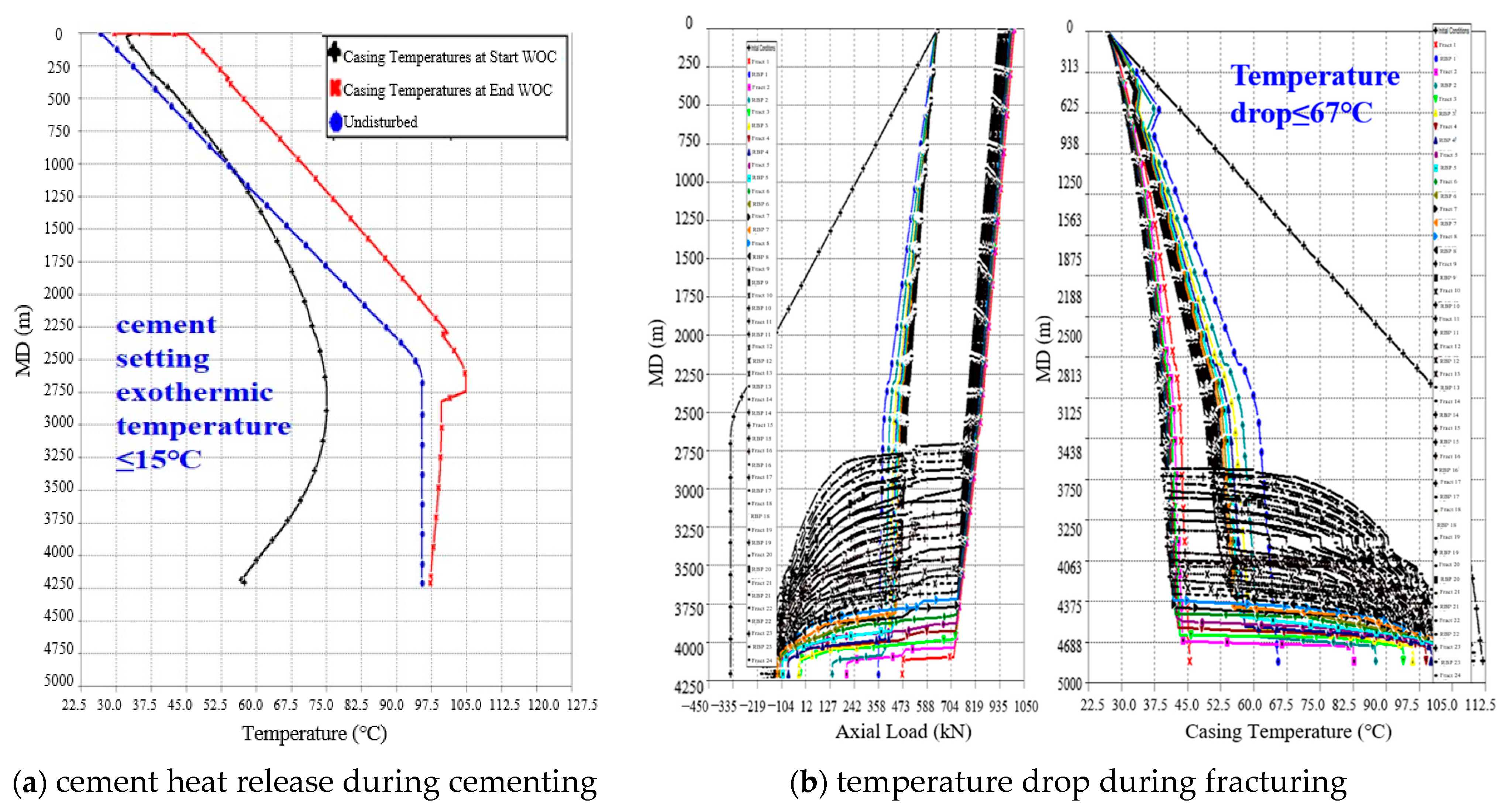
Considering the rotating speed under casing running condition, the heat release of cement solidification under cementing condition, and the temperature drop of fracturing fluid under fracturing condition comprehensively, the safe service margin of the casing is large, meeting the requirements of working conditions.
(3)
By using the method of unconventional oil and gas well casing string simulation tests and numerical simulation, the mechanical response of the whole wellbore and the mechanism of bridge plug resistance are studied. An analytical model of the casing minimum drift diameter under the effect of formation slip is established, which provides a technical support for the cement parameter selection and the measures to prevent casing deformation.

Author Contributions

Writing—original draft preparation, B.Z.; formal analysis, X.Z.; funding acquisition, J.C.; data curation, F.Z. and Y.S.; validation, Y.W. (Yao Wang) and J.H.; methodology, Y.W. (Yezhong Wang) and Y.D. All authors have read and agreed to the published version of the manuscript.

Funding

This research was funded by the supports of the China National Petroleum Corporation (2021DJ2705), 2021DQ03(2022Z-10); the Study on Key Technologies of Production Increase and Transformation of Gulong Shale Oil (2021ZZ10-04).

Institutional Review Board Statement

Not applicable.

Informed Consent Statement

Not applicable.

Data Availability Statement

Not applicable.

Conflicts of Interest

The authors declare no conflict of interest.

References

  1. Landry, G.; Welty, R.D.; Thomas, M.; Vaughan, M.L.; Tatum, D. Bridging the gap: An integrated approach to solving sustained casing pressure in the cana woodford shale. In Proceedings of the SPE Well Integrity Symposium, Galveston, TX, USA, 2–3 June 2015; p. 174525. [Google Scholar]
  2. Blake, R. Extending lateral length using casing floatation to reduce field development cost in shale gas plays. In Proceedings of the SPE Annual Technical Conference and Exhibition, Amsterdam, The Netherlands, 27 October 2014; p. 170888-MS. [Google Scholar]
  3. Yin, H.; Zhang, Y.Y. A quantitative evaluation method for the effect of temperature on casing collapsing strength: A case study of large-scale hydraulic fracturing in shale gas horizontal wells. Nat. Gas Ind. 2016, 36, 73–77. [Google Scholar]
  4. Tian, Z.L.; Shi, L.; Qiao, L. Research of and countermeasure for wellbore integrity of shale gas horizontal well. Natur. Gas Ind. 2015, 35, 70–76. [Google Scholar]
  5. Lian, W.; Li, J.; Liu, G.H.; Xi, Y.; Wu, L.H.; Chen, L.P. Analysis of casing stress difference at different positions in horizontal segment of shale gas well during fracturing process. Drill. Prod. Technol. 2020, 43, 11–14. [Google Scholar]
  6. Chen, Z.W.; Xiang, D.G.; Zhang, F.Z.; Mengke, A.; Zirui, Y.; Zhenyuan, J. Fault slip and casing deformation caused by hydraulic fracturing in Changning-Weiyuan Blocks, Sichuan: Mechanism and prevention strategy. Pet. Sci. Bull. 2019, 4, 364–377. [Google Scholar]
  7. Sugden, C.; Johnson, J.; Chambers, M.; Ring, G.; Suryanarayana, P.V. Special considerations in the design optimization of high rate, Multistage Fractured Shale Wells. In Proceedings of the IADC/SPE Drilling Conference and Exhibition, San Diego, CA, USA, 6–8 March 2012. SPE-151470-MS. [Google Scholar]
  8. Deenadayalu, C.; Suarez-Rivera, R. The effect of horizontal completions on the breakdown pressures of anisotropic gas shales. Am. Rock Mech. Assoc. 2010, 10, 27–35. [Google Scholar]
  9. Wang, X.Z.; Qu, Z.; Dou, Y.H. Influence of Geometrical and Physical Parameters of Cement on Loads of Casing and Cement. Adv. Mater. Res. 2013, 634–638, 3591–3594. [Google Scholar] [CrossRef]
  10. Qu, Z.; Wang, X.Z.; Dou, Y.H. Analytic and Numerical Solutions of Load and Stress of Casing and Cement in Cementing Section. Appl. Mech. Mater. 2013, 268–270, 721–724. [Google Scholar] [CrossRef]
  11. Deng, J.G.; Tian, H.; Wang, Z.Z.; Zhou, J.L. Laboratory study of casing strength under nonuniform load. Rock Soil Mech. 2005, 26, 855–858. [Google Scholar]
  12. Zou, L.Z.; Deng, J.Z.; Zeng, Y.J.; Li, J.; Dong, W.Z. Investigation of casing load calculation and casing design for deep salt formation. Pet. Drill. Tech. 2008, 36, 23–27. [Google Scholar]
  13. Han, L.H.; Yang, S.Y.; Wei, F.Q.; Ye, X.Q.; Wang, J.J. Casing Deformation Mechanism and Controlling Method for Shale Gas Well under Complex Fracture Environment. Pet. Tubul. Goods Instrum. 2020, 6, 16–23. [Google Scholar]
  14. Li, Y.; Liu, S.Q.; Wang, Z.H. Effect of cement thickness and its mechanical parameters on cement stress. Oil Drill. Prod. Technol. 2010, 32, 37–40. [Google Scholar]
Figure 1. True stress–strain curves of P110 and Q125 casings.
Processes 11 00695 g001
Figure 2. Distribution of casing axial force at different speeds under casing running conditions.
Processes 11 00695 g002
Figure 3. Effect of temperature on casing strength.
Processes 11 00695 g003
Figure 4. Deformation morphology of shale gas horizontal casing.
Processes 11 00695 g004
Figure 5. The relationship between the deformation location and fault.
Processes 11 00695 g005
Figure 6. Verification results of production casing string.
Processes 11 00695 g006
Figure 7. Schematic diagram of casing deformation and bridge plug obstruction: (a) before deformation; (b) after deformation.
Processes 11 00695 g007
Figure 8. Casing deformation morphology after 40 mm shear deformation: (a) test equipment; (b) test morphology; (c) equivalent stress distribution diagram of finite element simulation.
Processes 11 00695 g008
Figure 9. Deformation morphology of casing–cement sheath after 40 mm shear deformation: (a) casing–cement sheath after test; (b) casing after test; (c) equivalent stress distribution diagram.
Processes 11 00695 g009
Figure 10. Simulation results when the elastic modulus of cement sheath is 9 Gpa: (a) displacement; (b) equivalent plastic strain.
Processes 11 00695 g010
Figure 11. Simulation results when the elastic modulus of cement sheath is 9 Gpa: (a) stress triaxiality; (b) load.
Processes 11 00695 g011
Figure 12. Equivalent stress distribution of cement-sheath with wall thickness of 50.8 mm.
Processes 11 00695 g012
Figure 13. Effect of cement sheath wall thickness on casing diameter.
Processes 11 00695 g013
Figure 14. Schematic diagram of casing–cement sheath–wall surrounding rock combination.
Processes 11 00695 g014
Figure 15. Relation between test value and calculated value of casing minimum drift diameter.
Processes 11 00695 g015
Table 1. Diameter parameters under different cement sheath wall thicknesses.
Wall Thickness/mmH1/mmH2/mmHmin/mm∆H/mm
50.8087.73.1684.5429.76
48.6087.383.3284.0630.24
46.5086.773.5983.1831.12
44.4586.494.0882.4131.89
41.5086.444.1682.2832.02
38.1086.294.2182.0832.22
Disclaimer/Publisher’s Note: The statements, opinions and data contained in all publications are solely those of the individual author(s) and contributor(s) and not of MDPI and/or the editor(s). MDPI and/or the editor(s) disclaim responsibility for any injury to people or property resulting from any ideas, methods, instructions or products referred to in the content.

