Abstract
The automotive industry has been developed over the years to build lighter and more efficient vehicles; however, the manufacturing processes still have an important environmental impact starting from the acquisition of the raw material until the end of its useful life. In this sense, life cycle engineering contributes to solve the environmental issues produced by the traditional manufacturing industry by considering a process that evaluates the technical aspects of the product but also weights the importance of the environmental impact. However, since there are some alternatives that can be considered as suitable for their technical, environmental, or cost qualities, the multicriteria decision methods used as an engineering tool have been useful to balance all the needed criteria in order to make the best selection. In this sense, this research provided an analysis of five materials that could be used in a rack and pinion system and were submitted to a process of life cycle analysis to consider the environmental parameters as part of the criteria to be assessed by the multicriteria decision methods such as entropy, the Technique of Order Preference Similarity method, the complex proportional assessment method, and the multicriteria optimization and compromise solution, leading to the selection of the best material to be considered for a rack and pinion system. In this sense, the process allowed us to conclude that some materials that are useful can be evaluated by multicriteria decision methods regarding the life cycle analysis, contributing to the application of these methods to make a more environmentally responsible material selection for automotive parts. Furthermore, among all the materials, the best suited for the rack and pinion system was the AISI 4340, which was validated by finite elements simulation, showing that the selection was optimal with a maximum stress of 216.14 MPa, a maximum deformation of 0.0081 mm, and a minimum safety factor of 3.56. In this sense, the simulation validated the selection made before, guaranteeing that the methods used are feasible for automotive applications.
1. Introduction
The utilization of sustainable materials has become a worldwide tendency and its development was born as a response to the environmental and social impacts of economic growth. In this sense, the automotive industry contributes in a significant way to the consumption of energetic resources and the production of pollutant emissions [1], considering that the manufacturing industry is one of the most common sources of air pollution [2]. Moreover, by the year 2015 the metallurgic industries that are responsible for the extraction of the materials required to build an automobile produced 320,865 million tons of CO2 emissions [3]. In this sense, for example, the use of aluminum as an alternative to reduce weight and fuel consumption was well accepted, however, the production of 1 ton of aluminum demands the extraction of 4.2 tons of bauxite and has an energy cost of 13,000 kWh × ton−1 [4], meaning that the environmental impact begins from the first acquisition of the raw material. In this way, life cycle engineering (LCE) aims to reduce the pollution and waste of manufactured products and optimize its life cycle, where the life cycle assessment (LCA) has a well stablished approach, according to ISO-14040, of considering the full product life [5]. LCE has the definition of designing a product’s life cycle through choices about the concept, structure, process, and materials, visualizing the environmental consequences [6]. In this sense, the research of Delogu et al. combined the LCA methodology with the traditional design in the component design, material choice, and concept design, allowing the inclusion of environmental aspects with stablished procedures [7]. Moreover, research around the LCA on automobiles has studied different parts of the vehicle, where the research of Lopes Silva et al. analyzed the improvement of an eco-friendly manufacturing process of exhaust valves with a cradle-to-grave LCA procedure [8]. The author Das made a comparison of energy consumption and CO2 emissions in the utilization of aluminum vs. steel in the body of the vehicle, considering aspects such as manufacturing, use, and recycling [9]. Akhshik et al., studied the environmental impact of using natural and/or recycled fiber-reinforced composites in under the hood parts such as the battery tray, engine cover shield, cam cover, and oil pan, resulting in a reduction of greenhouse gases and energy savings [10]. However, there is not much research done to analyze the life cycle of the mechanical parts of the vehicle; in this sense, analyzing the LCA of a vital part such as the rack and pinon system is a topic of interest, because according to Chopane et al., the gearing systems of vehicles are the backbone of power transmission systems, where the steering components, including the rack and pinion, have the function of providing directional control over the vehicle [11] with the advantage of a high transmission efficiency, making the gear and rack appropriate to use in force and motion systems [12]. However, the selection for the material of these parts traditionally includes criteria such as cost, endurance to limit stress, ultimate tensile strength, and wear [13] but not the environmental matters. Furthermore, computational tools have been developed to make research on assessing the LCA easier. Here, the Eco-Audit software from CES Edupack has proved to be useful in investigations such as the analysis of the enhancement and the life cycle of a heat exchanger performed by Said et al., where the authors evaluated the life cycle of the tubes, shell, pipes, storage tank, and pump using this software as an innovative method [14].
Furthermore, a crucial part of the product design is the material selection, which can be a difficult task since the consideration of different alternatives in the market and characteristics must be oriented to find the ideal alternative [15]. In this way, the multicriteria decision methods (MCDM) have been used because it combines the preferences and performance of different materials and makes a selection based on sustainability objectives [16]. The MCDM uses weighting methods that can be subjective, taking into consideration the experience and knowledge of the decision maker, or can be objective since it determines the best choice by mathematical solving as in the entropy method [17,18] and can be used with other methods like the Technique for Order of Preference by Similarity to Ideal Solution (TOPSIS) which has been implemented in the fields of engineering and business in a successful way [19]. Furthermore, the MCDM have been used in the selection of materials for automotive parts in different researches, like in the study made by Dev, Aherwar, and Patnaik, where it performed the selection of the appropriate material for the development of a piston made with recycled porcelain as reinforcement. In this way, they used the entropy and the multicriteria optimization and compromise solution (VIKOR, for its Serbian acronym) method [20]. On the other hand, Stoycheva et al. showed how the MDCM can be used in the automotive manufacturing industry for making a qualitative selection of materials with sustainability objectives [16], and even more, the MCDM has been proved to be useful in the selection of experimental thermal materials for vehicles using the methods VIKOR, TOPSIS, and COPRAS [21].
Moreover, making the right selection of the material for a mechanical system considering the environmental aspects is important for the development regarding the functionality of the part with the replace material. In this way, the simulation by finite elements method (FEM) allows static and thermal analysis, and, thus, optimization leading to more reliable parts [22] where the pinion has to endure forces in the teeth due to the curved surface that pushes one against the other to produce the rotary motion [23], and that is the phenomenon that can be replicated with the FEM. In this sense, the research of Chen et al., using computational simulations, proved the importance of mesh performance on modified straight bevel gears, showing that the modifications on tooth end relief and symmetric crowns allows them to avoid the edge effect and alignment errors, hence, reducing the sensitivity of bending and meshing impacts and improving the results of bending fatigue [24] that can be directly associated to the LCA of the gears [24]. Lingbeek et al. developed a spring back compensation with finite elements deep drawing simulations which proved to be useful in feasibility checks and (re)design of deep drawing tools [25]. Szmytka et al. performed finite elements simulations to detect the areas that would suffer more and identify a potential lifetime of a diesel engine piston, making it possible to adjust the experimental values as close as possible to the real thermal conditions needed [26]. In the research of Chopane et al., a steering system was developed with the material Nylon 66 in the rack and pinion design, where the simulations showed that applying a moment of 13,000 N*mm−2 to the pinion in an anticlockwise direction gave a maximum deformation of 0.1811 mm and a maximum stress of 16.296 MPa, which is acceptable for the Nylon 66 [11], while a simulated structural transient comparison between the most preferred materials for manufacturing rack and pinion systems, revealed that the nickel aluminum bronze alloy got a von Mises stress of 0.001 MPa, making it the best [12].
Furthermore, the different research made in the selection of materials for the rack and pinion system have shown that different materials can fulfill the needs of the applications. In this sense, the materials that are considered suitable for the steering rack are the steel 41Cr4 annealed (AISI 5140), also the steel 20MoCr4 (AISI 8620) annealed [27] and the steel AISI 4340 are often used for the pinion [28]. Kusmoko and Crosky carried out research to characterize a wear resistance improvement of a pinion made of AISI 4140 that reached 45HRC [29]; in this sense, we were interested in using the basic material annealed. Lastly, the research of Vinodh and Jayakrishna suggested a change of material for the ABC company in India, the manufacturer of hydraulic power rack and pinion steering wheels, where the material AISI 1045 presented a reduction on environmental impact indicators such as carbon footprint, water eutrophication, air acidification, and total air consumed [30]. However, the selections made before have been limited by traditional selection methods or by technical considerations that did not consider the environmental aspects or both, hence, making the material selection by MCDM with LCA indicators is an important tool to be considered in the manufacturing process, taking into consideration that LCE has been determined as the application of technical and scientific principles to protect the environment [31]. Furthermore, the review research of Gbededo et al., about the life cycle sustainability analysis and approaches to sustainable manufacturing, holds an important state of the art overview where the LCA and the MCDM are mentioned only in the assessment of environmental impact of business, and optimization in tandem with sustainability objectives [32], but not as it was proposed in this research.
Considering the facts before exposure, the research problem to be solved relates to the optimization of material selection by the utilization of the MCDM regarding the LCA, considering an important vehicle part that is processed in the manufacturing industry. In this sense, the objective of this research proposed the utilization of the MCDM as an engineering tool that allows us to find a suitable material to be used for the rack and pinion part of a vehicle, where the selection considers the LCA of the candidate materials along with the technical and cost aspects; furthermore, the validation of the chosen material was made by a finite elements method simulation of the part in operative conditions.
2. Materials and Methods
The rack and pinion system is the most popular steering system in cars and is also the simplest. When the steering wheel is turned, the pinion at the end of the shaft moves along a linear toothed rack, transferring a rotary movement to a horizontal movement [33], this behavior is the base of the material selection and simulation. In this way, bibliographical research of suitable materials that have been previously described has been carried out before. However, these sources do not present all the technical information needed; hence, information on the materials’ properties was extracted from the level 3 library of the software CES-EDUPACK which has 4026 materials [34]. However, because the material AISI 1045 was not available in the software’s library, the next most likely steel was used, that being the AISI 1050 annealed. In this sense, the mentioned materials have been described by the software with applications in gears, engine parts, and crankshafts.
2.1. Computational Based Life Cycle Analysis Tool
The LCA takes into consideration the aspects associated with the product or processes such as energy, materials, and emissions. In this way, the analysis considers the indications expressed in the normative ISO 14040 for the LCA with the following framework:
- Definition of goals and scopes;
- Inventory Analysis;
- Impact assessment.
These three definitions interact with the interpretation and have direct applications on product development, and the results have been catalogued as useful inputs in decision-making processes [35].
The assessment method was performed by the utilization of the software CES-Edupack, which holds the database of the materials and has the Eco-Audit tool that allows it to enable the product designers to assess the environmental impact of the product, focusing on two environmental indicators, such as the energy usage and the CO2 footprint [36]. In this sense, the calculation of these two indicators was the scope definition for this research, regarding the process of extracting raw material to deliver a functional rack and pinion system, and regarding that these quantitative values are useful to assess the importance of the environmental impact on the MCDM. In this way, the process to calculate the embodied energy and the CO2 footprint of the candidate materials was performed following the decision flow chart expressed in the methodology of the research of Morini et al., who addressed the life cycle definition as “a consecutive and interlinked stages of a product system, from raw material acquisition or generation from natural resources to final disposal”, extracted from the ISO 14040, Environmental Management—Life Cycle Assessment—Principles and Framework [35,37]. In this way, the production of the parts were defined along with the process and disposal, followed by the transport and use, leading to the needed calculation results that will be compared and used as assessment values [37]. In this sense, Table 1 shows the evaluation parameters used by Morini et al., these are the parameters that the software considers according to the part. On the other hand, Table 2 displays the elements that are considered part of the transportation’s elements. In this sense, the declaration of these variables are made for every candidate material. However, it is important to mention that in this case the life cycle inventory only used 1 material for every analysis that was taken from the CES Selector Library, and the bill of materials was not considered.

Table 1.
LCA evaluation parameters [34].
Table 2.
Mobility conditions [34].
Furthermore, regarding the energy aspect, 4 stages were determined: material production, manufacturing, use, and end of life [38]. In this case, the same stages were considered, barring the use because there will be the same application for all alternatives, making the other three enough to assess the energy consumption and emissions.
The software had the option to introduce the use of the part; however, this was not considered since it was assumed that the use was for the same vehicle in the same conditions with the same endurance, meaning that there would be no difference between one material or another. Hence, following the definitions of the normative ISO 14040, every material has its own inventory analysis in Table 1 and Table 2 with the aforementioned conditions; in this sense, the impact assessment was reflected in the embodied energy and CO2 footprint values that were used to compare the materials between each other and allowed us to discuss the importance of this factor on the selection of the best material by multicriteria means. Therefore, the definition of goals, the inventory analysis, the impact assessment, and the interpretation were fulfilled between the definition of the method and the results that the normative ISO 14040 requires [35] by using the computation tool of Eco-Audit.
2.2. Multicriteria Decision Methods
The MCDM helped to assess the different mechanical properties considered important to developing a rack and pinion system, where the density of the materials is considered since lighter materials contribute to the better performance of the vehicles. On the other hand, since the rack and pinion system applies forces from one to another, it is important to regard the yield strength that manages deformations before breaking, compressive strength resists the axial forces of the pinion’s teeth when they are pressed against the rack, tensile strength endures the pulling forces in the root of the pinion when moving through the rack, and, considering that this system has a solid against solid component, its durability depends on the hardness of the material to avoid wear of the parts and the fatigue that damages the utility of the system over time [23]. Even more, the CO2 footprint and the energy consumption that were obtained from LCA analysis as parameters for decision making are regarded as the environmental aspects that should be diminished and were considered along with the price that makes a part affordable. Table 3 displays the materials and the properties used; also, in the application of the MCDM, the materials and criteria were coded and classified by their utility as follows:
Table 3.
Candidate materials’ properties [34].
- Material
- ○
- AISI 5140—M1
- ○
- AISI 8620—M2
- ○
- AISI 4340—M3
- ○
- AISI 4140—M4
- ○
- AISI 1050—M5
- Criteria
- ○
- Price ($*kg−1)—C1: Non-beneficial
- ○
- Density (kg*m−3)—C2: Non-beneficial
- ○
- Yield strength (MPa)—C3: Beneficial
- ○
- Compressive strength (MPa)—C4: Beneficial
- ○
- Tensile strength (MPa)—C5: Beneficial
- ○
- Hardness (HV)—C6: Beneficial
- ○
- Fatigue strength at 107 cycles (MPa)—C7: Beneficial
- ○
- CO2 footprint (kg)—C8: Non-beneficial
- ○
- Energy consumed (MJ)—C9: Non-beneficial
The classification of the criteria depended on the status where, if its value was greater, it had a better performance, and so, it was considered beneficial, and for the aspects that were better if its value was lower, then it was considered non-beneficial.
2.2.1. Entropy
The method of entropy that has been used to establish the objective weights of attributes was first proposed in 1948 by Shannon [39,40]. This method was performed following the steps described by Jahan et al. in their research of “A framework for weighting of criteria in ranking stage of material selection process” [41]. In this sense, this assessment technique allows more importance to be given to the attributes that are different for all the candidates, meaning that the attributes that have similar performance ratings are considered less important [41]. In this sense, the entropy method was considered because all the candidate materials were proven to be useful with the aforementioned technical and environmental considerations. However, the weighting must reflect the difference that can make a material to stand out.
The method was used as expressed by the author, where the decision matrix (xij) of Table 3 was transformed to a normalized matrix (pij) using the following equation:
i = 1, …, m; j = 1, …, n
Then the entropy (Ej)was calculated considering m as the number of criteria:
Lastly, with the calculated entropy, the weight (wj) for each criterion was found by normalizing the criteria.
2.2.2. VIKOR
The VIKOR method that is useful for multicriteria optimization of a complex system was developed as expressed by Opricovic and Tzeng. In this method the selection is made by looking for the closest to ideal option in the presence of conflicting criteria [42]. In this sense, the VIKOR method was first introduced by Opricovic as a technique to rank alternatives that considers conflicting criteria [43,44]; hence, the method was needed for this evaluation because the materials were being assessed not only for their technical performance, but for their environmental impact, leading to conflicting analysis.
The method starts with the determination of the best () and worst () values, comparing the features of each material.
Where: The beneficial criteria are represented by ;
The non-beneficial criteria are represented by
In this way, the method continues by calculating the values Si and Ri that are considered rankings by themselves. Where the values of wj are transposed to wi.
In this way, the method uses the values of Sj to determine S* = Sj; = Sj. On the other hand, the values of Rj for R* = Rj; = Rj, and this application uses a value v = 0.5 as the maximum group of utility to calculate the following values of Qj. In this sense, the ranking of the values is sorted under the criteria that the closer to zero, the better.
Furthermore, the calculated values of Qj allow the materials to be ranked; however, the best material must fulfil the acceptable advantage condition (C1), ruled by Equation (7), where Q(a′) represents the best material, Q(a″) the second best, and DQ is the number of alternatives calculated with Equation (8), where J represents the number of alternatives. Moreover, the acceptable stability condition (C2) states that the best ranked material of Qj must also be the best ranked for Sj and/or Rj.
In the case that these conditions are not satisfied, then it is necessary to declare a compromise solution. Therefore, for C1 the alternatives a′, a″, …, a(M) must be considered until finding the option closest to the best material regarding the following condition:
On the other hand, if only the condition C2 is not accomplished, then the compromised solution should consider the alternatives a′ and a″.
2.2.3. TOPSIS
The TOPSIS method is considered the second most popular MCDM worldwide and was used first by Hwang and Yoon in 1981 [45,46]. This method was developed for this research following the steps expressed in the research of Ma et al., aiming to find a solution that is near to a hypothetical best and far from the hypothetical worst, where the positive ideal solution is given the optimal values and the negative ideal solution has the set of worst values [1]. Because the VIKOR method can present compromised solutions, it is important to have another method to compare results; hence, the TOPSIS method that also looks for ideal solutions is a good method to complement the analysis.
In this way, the method used the same decision matrix of Table 2 and the weights calculated by the entropy method. The following steps are the calculation of the normalization matrix (X’ij) that eliminated the difference of magnitudes in the criteria by using Equation (10), and then the weighted (Bij) matrix was developed by utilizing Equation (11).
In this way, the determination of the positive ideal solution () and the negative ideal solution () followed the classification of the beneficial and non-beneficial criteria, expressing that for the beneficial criteria, refers to the maximum Bij, is the minimum Bij, and in the other direction, for the non-beneficial criteria, is the minimum value of Bij, as is the maximum value of Bij. Furthermore, with these values the Euclidean distances to the positive ideal solutions ) and the negative ideal solution () were calculated with Equations (12) and (13), respectively.
Finally, the closest to ideal solution () was calculated by applying Equation (14). These values were used to rank the alternatives by sorting them in decreasing order.
2.2.4. COPRAS
The method of complex proportional assessment (COPRAS) was presented for the first time by Zavadskas et al. to prioritize several alternatives based on the criteria weights [47,48]. This method was performed for this research following the process done by Chatterjee, Athawale, and Chakraborty in previous selection researches. This method allows the different options to be ranked by evaluating the significance and utility degree of the alternatives, assuming their direct and proportional dependence, and taking into consideration the weight granted to each criteria [49]. In this sense, because there is the possibility that the other methods do not agree on a best material, a third method that considers the utility of the winner is a useful tie breaker.
In this way, the method begins with the normalization of the decision matrix (rij) to compare all the criteria in a dimensionless state by using Equation (15), then this matrix is weighted (yij)with Equation (16).
Moreover, after the calculation of the weighted matrix these values are summated in groups divided by the classification of the criteria, where represents the weighted values of the beneficial criteria and represents the non-beneficial. The equations that rule these conditions for the positive solutions () and negative alternatives () are used as follows:
In this way, to determine the priorities of the alternatives, Equation (20) calculates the relative significance of the values (Qi), considering that is the minimum value of . Moreover, the ranking is displayed by calculating the quantitative utility (Ui) for the alternatives as a percentual range, with Qmax being the highest value of relative significance and 100% the most useful alternative to rank as expressed in Equation (20).
2.3. Computer Assisted Simulation
The selection of the best material for the rack and pinion allowed us to continue the validation of the system by computational means. In this sense, the system was designed according to the calculated specifications described in Table 4, using the constant values from Table 5, while following a referential model of a real rack and pinion system of a small vehicle.
Table 4.
Constant values definition [50].
Table 5.
Design calculation parameters [50].
Furthermore, the parts and the ensemble are modeled with the computer assisted design software, which is presented in Figure 1 along with the mesh and the applied force. The parameters that were used to do the simulation are presented in Table 6. It is also important to mention that according to the research of Chopane et al., the force that is produced in the rack of a formula supra car steering system simulates a momentum force of 13,000 N × mm [11], so this was the value that was used in the simulation.

Figure 1.
Rack and pinion assembly mesh and force.
Table 6.
Simulation parameters.
3. Results and Discussion
3.1. LCA Results
The results obtained from the software are displayed in Figure 2, showing the comparison of energy consumed and the CO2 footprint of every material through its life cycle, from the extraction of the raw material to the disposal and the end-of-life potential that each one has. In this sense, the most environmentally friendly material was the AISI 5140, followed by the AISI 1050. The research done by Vinodh and Jayakrishna, showed that in the manufacturing company ABC, the replacement of the material AISI 347 SS annealed with the AISI 1050 reduced the CO2 footprint by nearly 10 kg and the energy consumption by 93 MJ [30]; however, here, it could be seen that the AISI 5140 was even more environmentally friendly material and could be considered. The chart shows that the AISI 5040 needed less energy to be extracted and manufactured, and produced less CO2, while the transportation and disposal were the same; nevertheless, the end-of-life potential of the AISI 5040 was the worst, which meant that it was not as re-usable as the other materials in recycling matters.
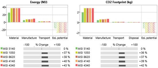
Figure 2.
LCA comparison chart.
The discussion made with the comparative impact on the embodied energy and the CO2 footprint was the impact assessment of the materials according to the normative ISO 14040 and the utilization of these values on the MCDM was part of the interpretation derived on the direct application of product development [35].
3.2. Entropy Method Results
The calculations for the entropy method through a normalized matrix Pij are presented in Table 7; the Ej values are displayed in Table 8 along with the weights (wj) that were used and a ranking of priority.
Table 7.
Entropy matrix Pij.
Table 8.
Entropy results.
In the research of Dev et al., they gave the priority to criteria such as friction coefficients and specific wear rates of the experimental data, making it possible to evaluate the alternatives in the following phase [20]. In this case, the method gave the yield strength and the compressive strength the greatest priority, meaning the heaviest criteria, which was important because the resistance of the system in operation depends on these properties. Next the energy consumption, which was part of the environmental aspect, followed by the hardness, which was important for the endurance of the parts, and the CO2 footprint of every material. In this sense, the entropy method provided priority not only to the mechanical aspects but also to the the environmental part that is our concern.
3.3. VIKOR Method Results
The results of the VIKOR method are displayed in Table 9, where the calculations of the operation representing the relationship between the weight granted by the entropy method and best and worst criteria can be seen; also, the summary of this relation in every material (Sj) and the maximum (Rj) are presented.
Table 9.
VIKOR calculations.
The following Table 10 computes the relation between Si, Rj, and the factor of maximum group utility with the value of v = 0.5, in the resulting Qi which determined the ranking, with the best result being the one closest to zero. However, there was no acceptable advantage since the difference of the best (AISI 4340) with the second best (AISI 4140) was 0.094 and should be greater than 1/(#alternatives-1) = 0.25. In this case, a compromise solution was developed looking for the closest of all the materials with a difference lower than 0.25. In this way, the acceptable stability of the best material was the best ranked with the Sj value and the best for Rj which was AISI 1050, which also placed as the best in the compromised rank.
Table 10.
VIKOR rank.
The VIKOR method along with the weighted criteria by the entropy method was used by Ishak, Sivakumar, and Mansor, to select the best matrix for a fiber metal laminate of an automotive front hood among four candidates, where the polypropylene stud was the best with an acceptable advantage greater than 0.33 and was also the best in the Sj and Rj ranking showing an acceptable advantage and stability [18], which meant that the material selected presented the best performance in comparison to the other candidates. In this case, a compromised ranking must be included because, as in the COPRAS method, there was a closeness of the materials. In this way, the materials AISI 4140 which had the second-best properties in compressive and yield strength was considered, and the AISI 1050 that was the best in price and the second best in environmental impact, was also considered good enough in performance compared to the AISI 4340.
3.4. TOPSIS Method Results
The TOPSIS method used Table 3 with the characteristic of the material for the calculations, then Table 11 presents the results for the normalization decision matrix. Next, Table 12 used the previous results and the weights found with the entropy method to calculate the weighted normalized matrix along with the positive ideal (Bj+) and negative ideal (Bj−) solutions.
Table 11.
TOPSIS normalized matrix.
Table 12.
TOPSIS normalized weighted matrix.
In this way, with this computed matrix the Euclidean ideal positive (Si+) and ideal negative (Si−) distances were calculated, followed by the closeness of each material to these ideals and the determination of the ranking in Table 13.
Table 13.
TOPSIS Rank result.
The results of the TOPSIS method revealed the material AISI 4340 as the best since its compressive strength and the yield strength were the best among all, but it is important to mention that the closest to ideal solutions had a factor of 0.66 and was not as good as the result of Ma et al., who selected the best material for an LCA of an automotive door panel with a factor of closeness of 0.96 [1], which was very close to the ideal 1. On the other hand, the research of Swapna et al. also found a factor of 0.74 of closeness in the selection of an aluminum alloy for automotive panels [19]. Both studies were over the present results, which does not mean that the material AISI 4340 is not worthy, but suggests that further comparison with other methods is needed.
3.5. COPRAS Method Results
The COPRAS method was performed, and the different matrix results were displayed in order. Table 14 displays the normalized decision matrix, followed by the weighted matrix that took into consideration the results of the entropy method in Table 15.
Table 14.
Normalized COPRAS decision matrix.
Table 15.
COPRAS weighted matrix.
Lastly, Table 16 displays the summary of the beneficial criteria (Si+), the non-beneficial criteria (Si−), the relative significance of the alternatives (Qi), the quantitative utility (Ui), and the ranking of the material.
Table 16.
COPRAS ranking.
The COPRAS method considered the material AISI 4340 as the best, meaning that this material had the best utility; however, all of the options had a high performance level. Compared with the research of Salazar Loor et al., in a selection of self-supported structure for light vehicles, the COPRAS method gave the best performance to the martensitic steel YS1200. Nevertheless, the second best received a performance level of 61.39% [15], meaning a clear advantage. This differs from the present research where the second best had a performance of 94% and the worst 86%, in this case all the materials proved to be good, but the AISI 4340 was the best.
On the other hand, even the VIKOR method had to declare a compromised ranking where three materials were considered worthy, the COPRAS method showed that the performance of all materials were very close to each other, and the TOPSIS method did not show a clear closest to an ideal solution factor of 1. However, in all the methods the material AISI 4340 was the best. Even if this material could be considered the most expensive and environmentally harmful, the difference when compared with the other materials was not large enough to diminish the technical aspects that made it stand as the best. However, the methods also proved that the other materials were also competitive, but for this research, the material AISI 4340 was chosen for the rack and pinion simulation.
Moreover, taking in mind that the weighting method considered was an objective method, in a comparative exercise a second selection was done with a subjective weighting method such as the analytical hierarchy process (AHP). In this sense, the method was performed following the steps described by Saaty in 1980 on the work of Odu [51]. In this way, the subjective criteria assessment provided the following weights for the criteria, displayed in Table 17. Considering that all the selected materials were proved to be useful in the application, this subjective weighting declared the environmental aspects as the most important criteria, followed by the mechanical aspects of yield strength and compressive strength. All the calculations of this weighting are displayed in Appendix A.
Table 17.
AHP weight.
Therefore, with this subjective weighting, the calculations of the different MCDM also changed as displayed in Table 18. Once again, all the calculations made for these methods are displayed in Appendix A.
Table 18.
Ranking with subjective weight.
In this way, the comparative rankings chose the material AISI 4340 as the best material once more. However, for this case the closeness of the ranking in every method was greater, where the acceptable advantage of the materials in the VIKOR method was narrow down, presenting a compromised solution that declares a tie of every material as the best. The TOPSIS ranking showed the material AISI 5140 as the third best, and COPRAS placed the same material in second place with a difference of 4% of utility compared to the best. Hence, considering the environmental aspects as the most important criteria reflected a considerable impact on the selection, but the great mechanical properties of the AISI 4340 still made it the best.
3.6. Simulation
The design of the rack and pinion system was conducted according to the calculations, Table 19 presents the results of the calculations that make the design of the system possible in the CAD environment. Moreover, Figure 3, Figure 4 and Figure 5 display the results of simulation of the system with the applied force of 13,000 N × mm, showing the deformations, stress, and safety factor present in the pinion, respectively.
Table 19.
System sizes.
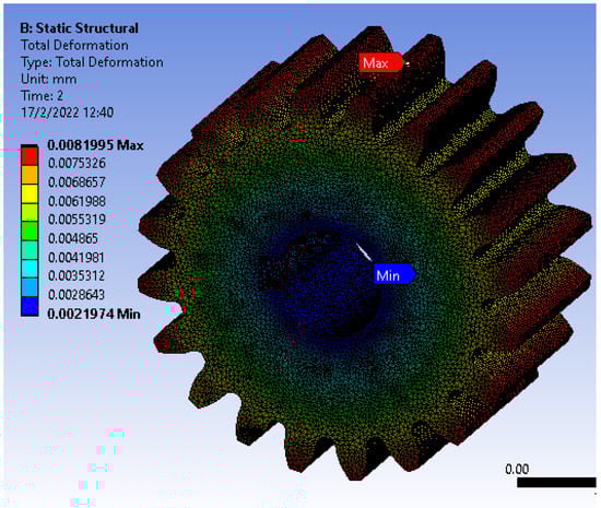
Figure 3.
Pinion deformation.
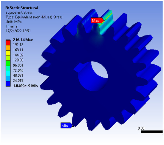
Figure 4.
Pinion stress.
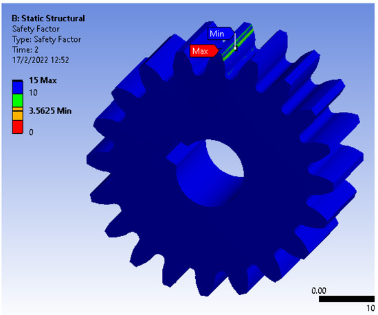
Figure 5.
Pinion safety factor.
In the results presented by Ramesh for the same system simulation, the maximum von Mises stress resistance found was in the material graphite cast iron with 124.38 MPa, and in the same material the deformation was 0.0783 mm [12]. Compared with our results where the proposed design must bear a maximum stress of 216.14 MPa and the deformation reached 0.0081 mm, meaning that the geometry and conditions of our model were more difficult for the material, but it could resist better because the deformation was lower. Moreover, for the safety factor, the Shigley’s Mechanical Engineering Design book mentioned that even for the most difficult operations with a heavy shock in the prime mover and in the driven machine, the safety factor must be 2.25 or greater [23], in this case the safety factor was 3.56, making the material AISI 4340 safe to use. Furthermore, to prove the accuracy of the simulation, a convergence test was performed with the results shown in Figure 6.
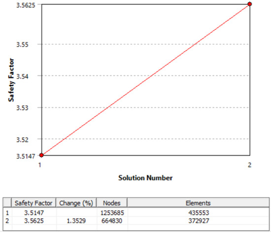
Figure 6.
Convergence result.
However, even though the results of simulation validated the material selection, it is important to point out that the LCA allows for an approximate idea of how every material may contribute to the environmental problems, but it has the limitations of manufacturing processes not being considered due the different policies of every enterprise and their countries. Furthermore, another limiting aspect is the time spent on the analysis of the MCDM and simulation, which may have a cost impact on the industry that should be considered.
4. Conclusions
The present research developed an alternative to material selection by using the multicriteria decision methods as a tool to make an optimized selection for parts in the automotive industry. Furthermore, the analysis considered not only the technical features of the materials but also the environmental aspects, with both being analyzed from an objective perspective, making it different from the traditional selection methods. In this sense, this method led to a responsible selection that was validated by computational means, leading us to conclude that the life cycle analysis and the multicriteria decision method are coherent with the manufacturing processes.
The multicriteria decision methods allowed for the selection of the best material for a rack and pinion system, and the multicriteria optimization and compromise solution method provided a compromised solution, the Technique for Order of Preference by Similarity to Ideal Solution and the complex proportional assessment methods helped reinforce the selection made by providing their own selection that was in agreement between them.
The multicriteria methods provide balance between the technical and environmental issues, but the best material was the one with the best compressive and yield strength due to the fact that the carbon footprint and the energy consumption did not have a significant difference to lower the priority of the technical aspects. Even more, when the criteria were weighted on a subjective basis where the environmental aspects were considered the most important, the advantage between the materials narrowed, but the material with the best technical aspects remained the best.
Among the different materials used for the rack and pinion system, there was a difference in the carbon footprint and energy consumption obtained by the life cycle analysis, but this was not significant, except for the AISI 5140 that had a clear environmental advantage over the others.
The simulation proved that even though the stress that the pinion must endure is very important, it manages it very well, making the deformation minimal and maintaining the safety factor over the requirement, which confirms that the technical property of the material compensates for the environmental issues.
The present research proved that the utilization of life cycle analysis and multicriteria decision methods can lead to a responsible material selection that can be validated by computational means. However, it did not consider the cost and time of computing the selection process. In this sense, it is recommended to bear in mind these considerations at the moment of applying these solutions in the manufacturing industry.
Author Contributions
Conceptualization: J.V., J.M.-G. and J.F.N.; Methodology: J.V., J.M.-G. and J.F.N.; Software: J.V., J.M.-G. and J.F.N.; Validation: J.V., J.M.-G. and J.F.N.; Formal Analysis: J.F.N. and J.M.-G.; Investigation: J.V., J.M.-G. and J.F.N.; Resources: J.V.; Writing—Original draft preparation: J.V. and J.F.N.; Writing—Review and editing: J.M.-G.; Visualization: J.F.N.; Supervision: J.M.-G.; Project Administration: J.M.-G.; Funding acquisition: J.M.-G. All authors have read and agreed to the published version of the manuscript.
Funding
This research takes part of the project Selection, characterization and simulation of phase change materials for thermal comfort, cooling and energy storage. This project is part of the INEDITA call for R&D research projects in the field of energy and materials. This research takes part of the project P121819, Parque de Energias Renovables funded by Universidad International SEK.
Data Availability Statement
The data reported in this research can be found at https://drive.google.com/file/d/1TFFUP7aRUKBqPUhIMQ9NBClAlP3KGj-F/view?usp=sharing (accessed on 26 January 2022).
Conflicts of Interest
The authors declare that the research was conducted in the absence of any commercial or financial relationships that could be construed as a potential conflict of interest.
Appendix A
Table A1.
AHP weight.
Table A1.
AHP weight.
| Criteria | C1 | C2 | C3 | C4 | C5 | C6 | C7 | C8 | C9 |
|---|---|---|---|---|---|---|---|---|---|
| C1 | 1.00 | 3.00 | 0.14 | 0.14 | 0.33 | 0.20 | 0.20 | 0.17 | 0.17 |
| C2 | 0.33 | 1.00 | 0.14 | 0.14 | 0.33 | 0.20 | 0.20 | 0.17 | 0.17 |
| C3 | 7.00 | 7.00 | 1.00 | 2.00 | 5.00 | 3.00 | 3.00 | 1.00 | 1.00 |
| C4 | 7.00 | 7.00 | 0.50 | 1.00 | 5.00 | 3.00 | 3.00 | 0.33 | 0.33 |
| C5 | 3.00 | 3.00 | 0.20 | 0.20 | 1.00 | 0.33 | 0.33 | 0.20 | 0.20 |
| C6 | 5.00 | 5.00 | 0.33 | 0.33 | 3.00 | 1.00 | 1.00 | 0.33 | 0.33 |
| C7 | 5.00 | 5.00 | 0.33 | 0.33 | 3.00 | 1.00 | 1.00 | 0.33 | 0.33 |
| C8 | 6.00 | 6.00 | 1.00 | 3.00 | 5.00 | 3.00 | 3.00 | 1.00 | 1.00 |
| C9 | 6.00 | 6.00 | 1.00 | 3.00 | 5.00 | 3.00 | 3.00 | 1.00 | 1.00 |
| Summatory | 40.33 | 43.00 | 4.65 | 10.15 | 27.67 | 14.73 | 14.73 | 4.53 | 4.53 |
Table A2.
AHP normalized matrix.
Table A2.
AHP normalized matrix.
| C1 | C2 | C3 | C4 | C5 | C6 | C7 | C8 | C9 |
|---|---|---|---|---|---|---|---|---|
| 0.02 | 0.07 | 0.03 | 0.01 | 0.01 | 0.01 | 0.01 | 0.04 | 0.04 |
| 0.01 | 0.02 | 0.03 | 0.01 | 0.01 | 0.01 | 0.01 | 0.04 | 0.04 |
| 0.17 | 0.16 | 0.21 | 0.20 | 0.18 | 0.20 | 0.20 | 0.22 | 0.22 |
| 0.17 | 0.16 | 0.11 | 0.10 | 0.18 | 0.20 | 0.20 | 0.07 | 0.07 |
| 0.07 | 0.07 | 0.04 | 0.02 | 0.04 | 0.02 | 0.02 | 0.04 | 0.04 |
| 0.12 | 0.12 | 0.07 | 0.03 | 0.11 | 0.07 | 0.07 | 0.07 | 0.07 |
| 0.12 | 0.12 | 0.07 | 0.03 | 0.11 | 0.07 | 0.07 | 0.07 | 0.07 |
| 0.15 | 0.14 | 0.21 | 0.30 | 0.18 | 0.20 | 0.20 | 0.22 | 0.22 |
| 0.15 | 0.14 | 0.21 | 0.30 | 0.18 | 0.20 | 0.20 | 0.22 | 0.22 |
Table A3.
AHP consistency calculation.
Table A3.
AHP consistency calculation.
| N × W | (N × W)/Weight | Consistency | ||
|---|---|---|---|---|
| C1 | 0.25 | 9.06 | CI | 0.08 |
| C2 | 0.19 | 9.20 | Ri | 1.45 |
| C3 | 1.93 | 9.77 | CR | 0.05 |
| C4 | 1.42 | 10.00 | ||
| C5 | 0.39 | 9.38 | ||
| C6 | 0.78 | 9.57 | ||
| C7 | 0.78 | 9.57 | ||
| Average | 9.96 | |||
Table A4.
VIKOR calculations (AHP).
Table A4.
VIKOR calculations (AHP).
| Material | C1 | C2 | C3 | C4 | C5 | C6 | C7 | C8 | C9 | Sj | Rj |
|---|---|---|---|---|---|---|---|---|---|---|---|
| M1 | 0.004 | 0.021 | 0.197 | 0.142 | 0.035 | 0.061 | 0.047 | 0.000 | 0.000 | 0.508 | 0.197 |
| M2 | 0.012 | 0.000 | 0.093 | 0.067 | 0.042 | 0.082 | 0.062 | 0.179 | 0.181 | 0.717 | 0.181 |
| M3 | 0.028 | 0.000 | 0.000 | 0.000 | 0.000 | 0.000 | 0.000 | 0.203 | 0.203 | 0.434 | 0.203 |
| M4 | 0.007 | 0.000 | 0.062 | 0.044 | 0.017 | 0.023 | 0.004 | 0.188 | 0.188 | 0.534 | 0.188 |
| M5 | 0.000 | 0.000 | 0.117 | 0.084 | 0.022 | 0.037 | 0.017 | 0.174 | 0.175 | 0.626 | 0.175 |
Table A5.
TOPSIS normalized matrix (AHP).
Table A5.
TOPSIS normalized matrix (AHP).
| Material | C1 | C2 | C3 | C4 | C5 | C6 | C7 | C8 | C9 |
|---|---|---|---|---|---|---|---|---|---|
| M1 | 0.417 | 0.452 | 0.334 | 0.334 | 0.401 | 0.404 | 0.423 | 0.339 | 0.337 |
| M2 | 0.454 | 0.446 | 0.443 | 0.443 | 0.377 | 0.365 | 0.406 | 0.466 | 0.466 |
| M3 | 0.528 | 0.446 | 0.540 | 0.540 | 0.527 | 0.522 | 0.476 | 0.482 | 0.482 |
| M4 | 0.428 | 0.446 | 0.475 | 0.475 | 0.468 | 0.477 | 0.471 | 0.472 | 0.472 |
| M5 | 0.396 | 0.446 | 0.418 | 0.418 | 0.448 | 0.451 | 0.457 | 0.462 | 0.462 |
Table A6.
TOPSIS normalized weighted matrix.
Table A6.
TOPSIS normalized weighted matrix.
| Material | C1 | C2 | C3 | C4 | C5 | C6 | C7 | C8 | C9 |
|---|---|---|---|---|---|---|---|---|---|
| M1 | 0.012 | 0.009 | 0.066 | 0.047 | 0.017 | 0.033 | 0.026 | 0.069 | 0.068 |
| M2 | 0.013 | 0.009 | 0.088 | 0.063 | 0.016 | 0.030 | 0.025 | 0.095 | 0.095 |
| M3 | 0.015 | 0.009 | 0.107 | 0.077 | 0.022 | 0.043 | 0.029 | 0.098 | 0.098 |
| M4 | 0.012 | 0.009 | 0.094 | 0.067 | 0.020 | 0.039 | 0.029 | 0.096 | 0.096 |
| M5 | 0.011 | 0.009 | 0.082 | 0.059 | 0.019 | 0.037 | 0.028 | 0.094 | 0.094 |
| Bj+ | 0.011 | 0.009 | 0.107 | 0.077 | 0.022 | 0.043 | 0.029 | 0.069 | 0.068 |
| Bj− | 0.015 | 0.009 | 0.066 | 0.047 | 0.016 | 0.030 | 0.025 | 0.098 | 0.098 |
Table A7.
TOPSIS rank result (AHP).
Table A7.
TOPSIS rank result (AHP).
| Material | Si+ | Si− | Ci | Rank |
|---|---|---|---|---|
| AISI 5140 | 0.050 | 0.042 | 0.454 | 3 |
| AISI 8620 | 0.044 | 0.027 | 0.382 | 4 |
| AISI 4340 | 0.042 | 0.050 | 0.546 | 1 |
| AISI 4140 | 0.042 | 0.035 | 0.456 | 2 |
| AISI 1050 | 0.046 | 0.022 | 0.318 | 5 |
Table A8.
Normalized COPRAS decision matrix (AHP).
Table A8.
Normalized COPRAS decision matrix (AHP).
| Material | C1 | C2 | C3 | C4 | C5 | C6 | C7 | C8 | C9 |
|---|---|---|---|---|---|---|---|---|---|
| M1 | 0.188 | 0.202 | 0.151 | 0.151 | 0.181 | 0.182 | 0.190 | 0.153 | 0.152 |
| M2 | 0.204 | 0.199 | 0.201 | 0.201 | 0.170 | 0.165 | 0.182 | 0.210 | 0.210 |
| M3 | 0.238 | 0.199 | 0.244 | 0.244 | 0.237 | 0.235 | 0.213 | 0.217 | 0.217 |
| M4 | 0.192 | 0.199 | 0.215 | 0.215 | 0.211 | 0.215 | 0.211 | 0.213 | 0.213 |
| M5 | 0.178 | 0.199 | 0.189 | 0.189 | 0.202 | 0.203 | 0.205 | 0.208 | 0.208 |
Table A9.
COPRAS weighted matrix.
Table A9.
COPRAS weighted matrix.
| Material | C1 | C2 | C3 | C4 | C5 | C6 | C7 | C8 | C9 |
|---|---|---|---|---|---|---|---|---|---|
| M1 | 0.0053 | 0.0042 | 0.0299 | 0.0215 | 0.0076 | 0.0149 | 0.0118 | 0.0310 | 0.0308 |
| M2 | 0.0057 | 0.0042 | 0.0396 | 0.0285 | 0.0071 | 0.0135 | 0.0113 | 0.0426 | 0.0427 |
| M3 | 0.0067 | 0.0042 | 0.0482 | 0.0347 | 0.0099 | 0.0192 | 0.0132 | 0.0441 | 0.0441 |
| M4 | 0.0054 | 0.0042 | 0.0425 | 0.0305 | 0.0088 | 0.0176 | 0.0131 | 0.0432 | 0.0432 |
| M5 | 0.0050 | 0.0042 | 0.0373 | 0.0268 | 0.0084 | 0.0166 | 0.0127 | 0.0422 | 0.0423 |
Table A10.
COPRAS ranking.
Table A10.
COPRAS ranking.
| Material | Si+ | Si− | Qi | Ui | Rank |
|---|---|---|---|---|---|
| AISI 5140 | 0.086 | 0.071 | 0.200 | 96% | 2 |
| AISI 8620 | 0.100 | 0.095 | 0.186 | 89% | 5 |
| AISI 4340 | 0.125 | 0.099 | 0.208 | 100% | 1 |
| AISI 4140 | 0.112 | 0.096 | 0.198 | 95% | 3 |
| AISI 1050 | 0.102 | 0.094 | 0.189 | 91% | 4 |
References
- Ma, F.; Zhao, Y.; Pu, Y.; Li, J. A Comprehensive Multi-Criteria Decision Making Model for Sustainable Material Selection Considering Life Cycle Assessment Method. IEEE Access 2018, 6, 58338–58354. [Google Scholar] [CrossRef]
- Vidhi, R.; Shrivastava, P. A Review of Electric Vehicle Lifecycle Emissions and Policy Recommendations to Increase EV Penetration in India. Energies 2018, 11, 483. [Google Scholar] [CrossRef]
- Lin, B.; Xu, M. Regional differences on CO2 emission efficiency in metallurgical industry of China. Energy Policy 2018, 120, 302–311. [Google Scholar] [CrossRef]
- Marretta, L.; Di Lorenzo, R.; Micari, F.; Arinez, J.; Dornfeld, D. Material Substitution for Automotive Applications: A Comparative Life Cycle Analysis BT. In Leveraging Technology for a Sustainable World; Springer: Cham, Switzerland, 2012; pp. 61–66. [Google Scholar]
- Kaluza, A.; Kleemann, S.; Fröhlich, T.; Herrmann, C.; Vietor, T. Concurrent Design & Life Cycle Engineering in Automotive Lightweight Component Development. Procedia CIRP 2017, 66, 16–21. [Google Scholar] [CrossRef]
- Herrmann, C.; Dewulf, W.; Hauschild, M.; Kaluza, A.; Kara, S.; Skerlos, S. Life cycle engineering of lightweight structures. CIRP Ann. 2018, 67, 651–672. [Google Scholar] [CrossRef]
- Delogu, M.; Maltese, S.; Del Pero, F.; Zanchi, L.; Pierini, M.; Bonoli, A. Challenges for modelling and integrating environmental performances in concept design: The case of an automotive component lightweighting. Int. J. Sustain. Eng. 2018, 11, 135–148. [Google Scholar] [CrossRef]
- Silva, D.; Oliveira, J.A.; Filleti, R.A.P.; Oliveira, J.; Silva, E.; Ometto, A.R. Life Cycle Assessment in automotive sector: A case study for engine valves towards cleaner production. J. Clean. Prod. 2018, 184, 286–300. [Google Scholar] [CrossRef] [Green Version]
- Das, S. The life-cycle impacts of aluminum body-in-white automotive material. JOM 2000, 52, 41–44. [Google Scholar] [CrossRef]
- Akhshik, M.; Panthapulakkal, S.; Tjong, J.; Sain, M. The effect of lightweighting on greenhouse gas emissions and life cycle energy for automotive composite parts. Clean Technol. Environ. Policy 2019, 21, 625–636. [Google Scholar] [CrossRef]
- Chopane, A.; Gupta, S.; Ajit, A.; Kakroo, S.; Salve, A. Design and analysis of plastic gears in rack and pinion steering system for formula supra car. Mater. Today Proc. 2018, 5, 5154–5164. [Google Scholar] [CrossRef]
- Ramesh, R. Static and Transient Analysis of Rack and Pinion. Int. J. Res. Mech. Mechatron. Automob. Eng. 2005, 4, 45–50. Available online: http://search.ebscohost.com/login.aspx?direct=true&db=buh&AN=15864947&site=ehost-live (accessed on 21 January 2022).
- Suryavanshi, O.D.; Sathe, P.P.; Takey, M.A. Designing of the rack and pinion gearbox for all terrain vehicle for the competition Baja SAE India and enduro student India. Int. J. Res. Eng. Technol. 2017, 6, 79–84. [Google Scholar] [CrossRef]
- Said, Z.; Rahman, S.; Assad, M.E.H.; Alami, A.H. Heat transfer enhancement and life cycle analysis of a Shell-and-Tube Heat Exchanger using stable CuO/water nanofluid. Sustain. Energy Technol. Assess. 2019, 31, 306–317. [Google Scholar] [CrossRef]
- Loor, R.B.S.; Gómez, J.M.; Hoyos, J.C.R.; Cedeño, E.A.L. Selection of materials by multi-criteria methods applied to the side of a self-supporting structure for light vehicles. Int. J. Math. Oper. Res. 2020, 16, 139–158. [Google Scholar] [CrossRef]
- Stoycheva, S.; Marchese, D.; Paul, C.; Padoan, S.; Juhmani, A.-S.; Linkov, I. Multi-criteria decision analysis framework for sustainable manufacturing in automotive industry. J. Clean. Prod. 2018, 187, 257–272. [Google Scholar] [CrossRef]
- Nicolalde, J.F.; Yaselga, J.; Martínez-Gómez, J. Selection of a Sustainable Structural Beam Material for Rural Housing in Latin America by Multicriteria Decision Methods Means. Appl. Sci. 2022, 12, 1393. [Google Scholar] [CrossRef]
- Ishak, N.M.; Sivakumar, D.; Mansor, M.R. Thermoplastic matrix selection for fibre metal laminate using fuzzy VIKOR and entropy measure for objective weighting. J. Eng. Sci. Technol. 2017, 12, 2792–2804. [Google Scholar]
- Swapna, D.; Rao, C.S.; Kumar, D.S.; Radhika, S. AHP and TOPSIS based selection of aluminium alloy for automobile panels. J. Mech. Energy Eng. 2019, 3, 43–50. [Google Scholar] [CrossRef] [Green Version]
- Dev, S.; Aherwar, A.; Patnaik, A. Material Selection for Automotive Piston Component Using Entropy-VIKOR Method. Silicon 2020, 12, 155–169. [Google Scholar] [CrossRef]
- Nicolalde, J.; Cabrera, M.; Martínez-Gómez, J.; Salazar, R.; Reyes, E. Selection of a PCM for a Vehicle’s Rooftop by Multicriteria Decision Methods and Simulation. Appl. Sci. 2021, 11, 6359. [Google Scholar] [CrossRef]
- Stroia, M.D.; Moşteanu, E.D.; Virca, I.; Răduca, E.; Popescu, C.; Haţiegan, C. Case studies for automotive components using CAD and CAE techniques. J. Phys. Conf. Ser. 2020, 1426, 12047. [Google Scholar] [CrossRef]
- Budynas, R.G.; Nisbett, K.J. Shigley’s Mechanical Engineering Design, 9th ed.; McGraw-Hill Interamericana: Mexico City, Mexico, 2014. [Google Scholar]
- Chen, M.; Xiong, X.; Zhuang, W. Design and Simulation of Meshing Performance of Modified Straight Bevel Gears. Metals 2020, 11, 33. [Google Scholar] [CrossRef]
- Lingbeek, R.; Huétink, J.; Ohnimus, S.; Petzoldt, M.; Weiher, J. The development of a finite elements based springback compensation tool for sheet metal products. J. Mater. Process. Technol. 2005, 169, 115–125. [Google Scholar] [CrossRef] [Green Version]
- Szmytka, F.; Salem, M.; Rézaï-Aria, F.; Oudin, A. Thermal fatigue analysis of automotive Diesel piston: Experimental procedure and numerical protocol. Int. J. Fatigue 2015, 73, 48–57. [Google Scholar] [CrossRef] [Green Version]
- Reimpell, J.; Stoll, H.; Betzler, J.W. Steering. In The Automotive Chassis, 2nd ed.; Butterworth-Heinemann: Oxford, UK, 2001; pp. 266–306. [Google Scholar]
- Kumar, A.; Jayakumar, P.; Sharma, V.K. Microstructure and properties of thermomechanically treated and bake hardened AISI 4340 steel. Mater. Today Proc. 2019, 18, 848–860. [Google Scholar] [CrossRef]
- Kusmoko, A.; Crosky, A. A Study Wear Behaviour of Induction Hardened 4140 and Carburised 8617H Steels on 1040 Steel. Mater. Sci. Forum 2013, 773–774, 851–864. [Google Scholar] [CrossRef]
- Vinodh, S.; Jayakrishna, K. Environmental impact minimisation in an automotive component using alternative materials and manufacturing processes. Mater. Des. 2011, 32, 5082–5090. [Google Scholar] [CrossRef]
- Fitzgerald, A.; Proud, W.; Kandemir, A.; Murphy, R.J.; Jesson, D.A.; Trask, R.S.; Hamerton, I.; Longana, M.L. A Life Cycle Engineering Perspective on Biocomposites as a Solution for a Sustainable Recovery. Sustainability 2021, 13, 1160. [Google Scholar] [CrossRef]
- Gbededo, M.; Liyanage, K.; Garza-Reyes, J.A. Towards a Life Cycle Sustainability Analysis: A systematic review of approaches to sustainable manufacturing. J. Clean. Prod. 2018, 184, 1002–1015. [Google Scholar] [CrossRef] [Green Version]
- Dell, R.M.; Moseley, P.T.; Rand, D.A. Development of Road Vehicles with Internal-Combustion Engines. In Towards Sustainable Road Transport, 1st ed.; Academic Press: Cambridge, MA, USA, 2014; pp. 109–156. [Google Scholar]
- Granta Design Limited. CES-Edupack; Granta Design Limited: Cambridge, UK, 2019. [Google Scholar]
- ISO 14040:2006; Environmental management—Life cycle assessment—Principles and framework. International Organization for Standardization: Geneva, Switzerland, 2006; p. p. 20. Available online: https://www.iso.org/standard/37456.html (accessed on 21 January 2022).
- Granta Design Limited. About Eco-Audit Tool. 2019. Available online: https://support.grantadesign.com/resources/cesedupack/2019/help/topic.htm#t=html/eco/eco_about.htm%23material (accessed on 15 February 2022).
- Morini, A.A.; Ribeiro, M.J.; Hotza, D. Early-stage materials selection based on embodied energy and carbon footprint. Mater. Des. 2019, 178, 107861. [Google Scholar] [CrossRef]
- Song, Y.S.; Youn, J.R.; Gutowski, T.G. Life cycle energy analysis of fiber-reinforced composites. Compos. Part A Appl. Sci. Manuf. 2009, 40, 1257–1265. [Google Scholar] [CrossRef]
- Shannon, C.E. A Mathematical Theory of Communication. Bell Syst. Tech. J. 1948, 27, 379–423. [Google Scholar] [CrossRef] [Green Version]
- Kumar, R.; Singh, S.; Bilga, P.S.; Jatin; Singh, J.; Singh, S.; Scutaru, M.-L.; Pruncu, C.I. Revealing the benefits of entropy weights method for multi-objective optimization in machining operations: A critical review. J. Mater. Res. Technol. 2021, 10, 1471–1492. [Google Scholar] [CrossRef]
- Jahan, A.; Mustapha, F.; Sapuan, S.M.; Ismail, M.Y.; Bahraminasab, M. A framework for weighting of criteria in ranking stage of material selection process. Int. J. Adv. Manuf. Technol. 2012, 58, 411–420. [Google Scholar] [CrossRef]
- Opricovic, S.; Tzeng, G.-H. Compromise solution by MCDM methods: A comparative analysis of VIKOR and TOPSIS. Eur. J. Oper. Res. 2004, 156, 445–455. [Google Scholar] [CrossRef]
- Mardani, A.; Zavadskas, E.K.; Govindan, K.; Senin, A.A.; Jusoh, A. VIKOR Technique: A Systematic Review of the State-of-the-Art Literature on Methodologies and Applications. Sustainability 2016, 8, 37. [Google Scholar] [CrossRef] [Green Version]
- Opricovic, S. Multicriteria optimization of civil engineering systems. Fac. Civ. Eng. Belgrade 1998, 2, 5–21. [Google Scholar]
- Hwang, C.-L.; Yoon, K. Methods for Multiple Attribute Decision Making BT. In Multiple Attribute Decision Making: Methods and Applications a State-of-the-Art Survey; Hwang, C.-L., Yoon, K., Eds.; Springer: Berlin/Heidelberg, Germany, 1981; pp. 58–191. [Google Scholar]
- Çelikbilek, Y.; Tüysüz, F. An in-depth review of theory of the TOPSIS method: An experimental analysis. J. Manag. Anal. 2020, 7, 281–300. [Google Scholar] [CrossRef]
- Zavadskas, E.K.; Kaklauskas, A.; Turskis, Z.; Tamošaitienė, J. Selection of the effective dwelling house walls by applying attributes values determined at intervals. J. Civ. Eng. Manag. 2008, 14, 85–93. [Google Scholar] [CrossRef] [Green Version]
- Stefano, N.M.; Casarotto Filho, N.; Garcia Lupi Vergara, L.; Garbin Da Rocha, R.U. COPRAS (Complex Proportional Assessment): State of the art research and its applications. IEEE Lat. Am. Trans. 2015, 13, 3899–3906. [Google Scholar] [CrossRef]
- Chatterjee, P.; Athawale, V.M.; Chakraborty, S. Materials selection using complex proportional assessment and evaluation of mixed data methods. Mater. Des. 2011, 32, 851–860. [Google Scholar] [CrossRef]
- Mott, R.L.; Vavrek, E.M.; Wang, J. Machine Elements in Mechanical Design, 6th ed.; Pearson Education: New York, NY, USA, 2018. [Google Scholar]
- Odu, G. Weighting methods for multi-criteria decision making technique. J. Appl. Sci. Environ. Manag. 2019, 23, 1449. [Google Scholar] [CrossRef] [Green Version]
Publisher’s Note: MDPI stays neutral with regard to jurisdictional claims in published maps and institutional affiliations. |
© 2022 by the authors. Licensee MDPI, Basel, Switzerland. This article is an open access article distributed under the terms and conditions of the Creative Commons Attribution (CC BY) license (https://creativecommons.org/licenses/by/4.0/).