Abstract
Inkjet printing, initially invented for text and pattern printing, has been extensively used to fabricate electronic, mechanical, and even biological devices. Numerous reviews focused on the mechanisms, development, and application of inkjet printing have been published in recent years. However, a small review has focused on the satellite droplets during inkjet printing. Satellite droplets have long been recognized as an undesirable byproduct in the inkjet community since they potentially blur the printing patterns, polluting the printer and the air. Numerous efforts have been made to avoid or suppress the generation of satellite droplets since the inkjet’s birth. However, recent studies demonstrated the delicately utilizing of the satellite for realizing extremely high printing resolution otherwise impossible for the traditional inkjet printing. In this review, we focus on the formation mechanisms of satellites, efforts made to suppress satellites, and techniques developed to utilize satellites, distinguishing them from the existing inkjet printing reviews.
1. Introduction
Satellite droplets are formed during the fragmentation process of liquid filament, rim, film, or other slender structures that cannot hold their shape due to the high specific surface area. According to the Rayleigh–Plateau instability, the liquid column will lose its stability once the wavelength of surface disturbance is larger than its circumference. Initially, the term satellite was used in the astronomy field, which means the small bodies orbit an enormous body due to the universal gravitation, just as the moon orbits the earth. There are many answers to how the moon is formed; one is the collision hypothesis [1,2]. The collision between two drops [3,4,5,6,7,8] or between one drop and one liquid/solid surface [9,10,11,12,13,14] is ubiquitous in nature. Binary drop collisions with low velocity will merge [8], while a higher velocity will form rims/threads/filaments, which finally break into satellite droplets [3,4,5,6,7,8].
However, the detailed pinch-off process and the emergence of satellites are hard to clearly observe with the naked eye when drops strike on the liquid or solid surface, considering its very small geometric scale and transitory time scale. The invention of stroboscopic photography provides a powerful solution for capturing the periodic phenomenon by slightly regulating the phase shift between the actuator and the pulsed laser light. Extremely high time resolution can be achieved by reducing the phase difference between the two periods. Thanks to this stroboscopic photography technique, the first jet breakup process, the formation of main and satellite drops, and drop oscillations were captured by Savart in 1833 [15]. In 1887, Lenard noted that the time lag between successive drops was highly constant if the inflow of fluid was constant; he used this stroboscopic photography technique to capture the actual dynamic process of a dripping faucet [16]. Those images showed the dynamic formation process of the satellite droplets during the jet breakup process, which is too fast to be observed by the naked eyes. Since the invention of the continuous inkjet printing (CIJ) technique in the 1970s, stroboscopic photography has been ideal for capturing the periodic jet breakup process. The invention and generalization of inkjet printing, especially the drop on demand (DOD) inkjet printing techniques, have triggered more desire to expound on the pinching process of various kinds of liquid jets. The stroboscopic photography is no longer suitable for the DOD inkjet printing since the droplet’s ejection process might not be highly uniform. Thanks to the illumination of the Laser-Induced Fluorescence (iLIF) technique developed recently, the time resolution of a sub-microsecond can be achieved for investigating the pinch-off process of the DOD inkjet printing [17,18,19].
For the DOD inkjet printing, liquid drops are ejected from the orifice by the pulsed pressure wave in the chamber. The magnitudes of pressure impulse, the time integral of the pressure, determine how much and how fast the liquid can be ejected out. The kinetic energy obtained from the ejection process must overcome the surface energy to ensure successful detachment [20]. At the moment of detachment, the ejected liquid thread always adopts a shape similar to tadpoles. The momentum of the liquid at the bolus head drags the connecting area and consequently results in the thinning and forming of the tail. The first pinch-off of the tail marking the detachment usually happens close to the orifice. The pinching-off point separates the liquid out of the orifice into two parts. One part is the free liquid thread continuously flying forward, and the other part is the meniscus pinned at the edge of the orifice, which will undergo several withdrawal–extrusion periods due to the residual pressure oscillations within the chamber before being sucked back into the chamber.
After detachment, the evolution of the free liquid thread is mainly governed by the capillary force and Bernoulli force. The formation of the first satellite droplet is declared by the second pinch-off, the second satellite by the third pinch-off, and so on. The following factors, including the length–diameter ratio of the tail/thread, initial velocity distribution within it, surface tension, the viscosity of the liquid and solute in the liquid (surfactant, particles polymers, etc.), have a bearing on the pinch-off behaviors, in addition to the size, amount, velocity, and destination (recollected by the main drop or drift away) of the satellite droplets, as well as the size velocity of the main drop.
The typical radius of the main drops is similar to the radius of the orifice, whereas the typical radius (volume) of the satellites droplets is about 0.5~1 orders of magnitude (2~5) orders of magnitude) smaller than the radius (volume) of the main drops. Besides the size difference, a velocity difference exists between the main drop and the satellite droplets. In the case of several satellite droplets, the size and velocity of each satellite are also different, even if they are pinched off from the same tail. Bigger satellite droplets are typically formed at the root of the tail, whereas smaller satellites are formed at the end of the tail. The larger satellite droplets usually have a higher velocity than the main drop and can catch up and merge again with the main drop before hitting the printed surface. However, smaller satellite droplets with lower momentum are more likely to be blown away from the ejection axis by the lateral airflow and blur the printing patterns or suspend in the air as the aerosol after solvent evaporation; thus, contaminating the printer and the working environment.
Obviously, satellite droplets are unwelcome in the inkjet printing community since they potentially blur the printing patterns and pollute the printer. Almost from the invention of inkjet printing, efforts were made to avoid the formation of satellites and eliminate the adverse impact of satellites. In the review, we first review the formation mechanisms of satellite droplets, then the current methods adopted to avoid/suppress the formation of satellite, and finally, the methods developed to utilize the satellite droplets to achieve higher printing resolution than the resolution achieved by utilizing the main drops.
2. Formation Mechanisms of Satellite Droplets
2.1. Dimension Analysis of the Inkjet Printing
Satellite droplets are determined by the ink’s physical properties and the ejection parameters, such as ejection speed and size of the orifice. Typically, three dimensionless numbers, Reynolds, Weber, and Ohnesorge numbers, are adapted to characterize the behavior of the ejected liquid drops [20].
The Reynolds number is expressed as:
where v is the characteristic velocity, a is the characteristic length, and are the density and dynamic viscosity of the ink.
The Weber number is expressed as:
where is the surface tension of the ink.
The Ohnesorge number is expressed as:
To ensure a successful ejection, the drop must be endowed with sufficient energy to overcome the surface energy of the ink at the orifice, which can be estimated from the surface area of the ejection liquid and the surface tension. Drops cannot be ejected below a threshold ejection velocity given by Duineveld et al. [20] and Kang et al. [21]:
where is the nozzle diameter.
Substitute this into the equation for calculating the Weber number, and one can get the minimum Weber number for the drops’ ejection:
However, if the momentum of the droplet is too large, the droplet striking the substrate will splash. An investigation carried out by Stow and Hadfield [22] reported the following equation for calculating this threshold:
where is a function of surface roughness only [23].
Based on the above equation, a phase diagram in parameter space with coordinates Re and We was constructed by Derby [24,25], as shown in Figure 1a. The blue cyan dash line on the top right of Figure 1a is the threshold of splashing when drops impact the substrate. McKinley and Renardy [26] redrawn this critical phase diagram by replacing We with Oh, as shown in Figure 1b.
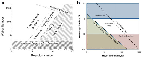
Figure 1.
The operating regimes of inkjet printing in the control parameter space of (a) Weber number We versus Reynolds number Re, and (b) Ohnesorge number Oh versus Reynolds number Re. Reproduced with permission from References [25,30].
The Ohnesorge number is the ratio of the Weber and Reynolds number. It is related to the property of the ink and the radius of the orifice, which is treated as the characteristic length for calculating the Ohnesorge number. The inverse of the Ohnesorge number, Z, defined as 1/Oh, is used more commonly for characterizing the drop ejection. At a low value of Z, viscous dissipation prevents drop ejection, whereas at a high value, the main drop is accompanied by a large number of satellite droplets. Reis & Derby [24,27] proposed the following range, 10 > Z > 1, for stable drop formation based on their numerical simulation of drop formation, as shown in Figure 1a. The value of Z lower than 0.67 could substantially contribute to viscous dissipation, finally preventing droplet ejection [24]. Tai et al. [28] reported that the value of Z should be 0.67 < Z < 50 for stably generating droplets, and the value of Z higher than 50 could result in the formation of satellite droplets due to the breakup of the thread trailing the main droplet. Other researchers [29,30] also reported different values for stable ejection.
The two diagrams show that the formation of satellite droplets occurs in the case of the larger Re and minor Oh, corresponding to higher ejection speed v and lower ink viscosity . The generation of satellite droplets is a complex process, and the precise physics and fluid mechanics of this process are still the subjects of much research.
2.2. Satellite Formation during DOD Inkjet Printing
The main stages of DOD drop formation include the following sequences: ejection and stretching of liquid, pinch-off of liquid thread from the nozzle exit, contraction of liquid thread, the breakup of liquid thread into the main drop in one or several satellites, and the recombination of main drop and satellites if satellites exist and have a velocity higher than the main drop, as shown in Figure 2a, b. There are also cases where the liquid thread can escape breakup and retract into only one drop, as shown in Figure 2c.
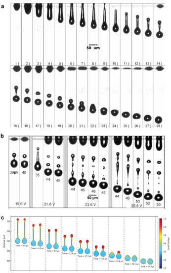
Figure 2.
(a) Typical ink ejection, satellite formation, and recollection process (b) longer liquid thread will lead to the formation of multi-satellite droplets with a wide range of size and velocity; (c) retraction of the thread into one drop without breakup. Reproduced with permission from References [17,31].
The liquid droplets are ejected from the orifice by the pressure pulse in the chamber, which is produced in response to a digital signal or waveform applied to the piezo actuator. The pressure within the chamber should be large enough to overcome the surface tension, viscous force, and inertia force of the ink for effective ejection [32].
At the early ejection stage, the meniscus is accelerated to a maximum velocity by the pressure inside the orifice. A liquid column with a diameter similar to the orifice is formed during this stage [31]. The acceleration stops once the pressure in the chamber falls below a critical value [32], then the stretching and thinning process takes place due to the inertia of the ejected inks. Further decrement of the pressure in the chamber will lead to the suction of liquid from the thread back into the nozzle [30]. Still, the surface area continues to increase until a maximum surface area is reached when the liquid thread pinches off from the nozzle exit, declaring the finish of the detachment. After that, the volume of the free liquid thread remains constant, but the surface area decreases toward a minimum value. Satellite droplets are formed due to the free liquid thread’s second, third, and fourth breakups. Obviously, the shape of the thread, especially the length and diameter, has a critical influence on the size and number of the satellite droplets. The breakup of the thread is similar to the liquid column’s breakup during the continuous ejection process since they have a similar slender shape. The breakup of the thread is governed by the surface tension, viscosity, and inertia of the ink.
For a nearly inviscid liquid, , the influence of viscosity can be neglected. The minimal radius Rmin(t) approaches zero, complying with the following famous equation:
where is the time remaining until pinch-off, and the prefactor is about 0.7 [33].
For viscous liquid, , the influence of viscosity cannot be neglected. The minimal radius Rmin(t) approaches zero as:
with a prefactor of about 0.071 [34].
These two scaling laws for the final phase of the pinch-off are confirmed in various experiments and numerical simulations [35,36].
For the inviscid and incompressible fluid, the shape evolution of the free liquid thread is governed by the unsteady Bernoulli equation:
where is the velocity potential, is the curvature [37,38]. This equation can be numerically solved by using a boundary-element method [37,39,40], and the results indicate a self-similar shape at the pinch-off region [37,41,42], which always adopts a unique shape with two cones of angles 18.1° and 112.8°, independent of the initial conditions, as shown in Figure 3a [37,43]. This finding is of great significance for understanding the formation mechanisms of satellite droplets since most of the inks are nearly inviscid. Take the second pinch-off as an example: the satellite is formed at the side with a cone angle of 18.1°, and the main drops at the side with a cone angle of 112.8°. Further pinching of the thread (if long enough) also complies with this discipline: smaller satellite droplets forming at the side with a cone angle of 18.1° and a larger one forming at the side with cone angles of 112.8°, as shown in Figure 3b.
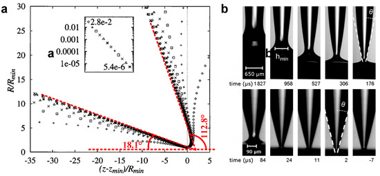
Figure 3.
(a) The pinch-off shapes at various times collapse onto two cones when rescaled with minimum radius Rmin(t) and centered on zmin(t). (b) Imaging of the pinch-off region for a dripping water droplet shows a conge angle of about 16.9° (upper) and 17.9° (lower). Reproduced with permission from References [37,43].
For the relatively viscous threads, the pinching off is more complex. There are no constant angles at the pinch-off region, distinguishing it from the inviscid pinch-off. The viscosity of the ink significantly affects the shape of the thread. Typically, the thread of viscous ink is much longer than the thread of lower viscosity. A recent investigation carried out by Fraters et al. [44] showed that besides the main tail attached to the main drop, the formation of a secondary tail also might occur. During inkjet printing, the secondary tail might further cascade into tertiary and quaternary tails and consequently results in the formation of satellites with a broad and tousy size distribution, as shown in Figure 4. This phenomenon was also observed by many other researchers [45,46].
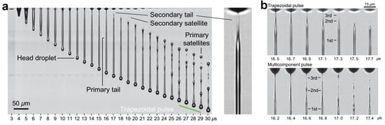
Figure 4.
(a) Secondary tail formation during the ejection of viscous inks; (b) appearance of tertiary tails. Reproduced with permission from Reference [44].
3. Satellite Droplets Elimination Strategies
3.1. Recollected by the Main Droplets or by Adjacent Satellite
Satellite droplets are formed due to the breakup of the tail, which has the same flying direction as the main droplets since they are ejected from the same nozzle. Therefore, without any lateral force, the satellite droplets should have the same trajectory as the main droplet and finally collide and merge with the main droplet, either before or after the main droplet settles on the targeted surface. This phenomenon has been confirmed both experimentally and numerically by Bos et al. [17] and other researchers [31].
There are many different cases of how satellites can be eliminated. The most common scenario is that satellites catch up and recombine with the main drop. The satellites must have a higher velocity than the main drop to ensure recombination. This velocity difference is due to the retraction of the thread during the pinch-off process. However, there are also cases where the satellites merge with the following larger satellite [31]. This phenomenon occurs typically in the case of multiple satellites due to the breakup of relatively long threads with low viscosity. In the case of multiple breakups, multiple satellites with a wide size and velocity distribution will be pinched off because of the emergence of second, third, and even fourth threads. The velocity of satellites is determined by the direction of the thread and how much recoil impulse it can get during the recoil process. According to Dijksman [47], the drag force exerted by the surrounding gaseous also significantly influences the velocity of the satellites. Smaller satellites encounter more significant deceleration in the air than larger ones. This might result in tiny drops merging with the following larger satellite [31].
The tiny satellite droplets will fail recombination with the main drops or adjacent satellites if they experience lateral air drag force and drift away from the jetting axis [48]. This always occurs during the fast-printing process since the fast relative movement between the printed surface and the nozzle will form lateral airflow. Besides the interference of lateral airflow, the nonaxisymmetric during the ejection process is another factor that will result in velocity deviation between the main droplet and the satellite droplet. If the hydrophilicity of the surface of orifices is not axisymmetric, the axis of the tail will lose axial symmetry during the ejection process. This will also result in a trajectory offset between the satellite and the main droplets.
Actually, this method just utilizes the scenario that the satellite and the main droplets have the same trajectory to recollect the satellite. It does not take any active actions to suppress the formation of the satellite. Therefore, it can be regarded as a passive satellite elimination method.
3.2. Tuning of the Pressure Pulse in the Chamber (Waveform Applied on the Piezo)
Besides the above passive satellite elimination method, some active methods can also suppress the satellite’s formation during the ejection process. Since the satellite droplets are formed due to the breakup of the tail after the main droplets governed by the Rayleigh-Plateau instability, the shape and velocity distribution of the tail after detachment should be the dominant factor determining the size, velocity, and the number of the satellite droplets.
The evolution of the liquid thread is related to the length of the liquid thread at pinch-off, which generally increases with increasing pressure pulse. For longer liquid threads, a wave-like instability occurs along the thread and results in the formation of several satellites of varying sizes; for the shorter threads, only one satellite is formed due to the end-pinching; and for the even shorter threads, it will contract into a single drop without breaking up after being ejected from the nozzle. Thus, one strategy for suppressing the satellite droplets is to minimize the tail’s length-diameter ratio, which could be realized by adjusting the driving signals [49]. A more effective way to do this is to tune the pressure pulse in the chamber, which is widely adopted by the piezoelectric inkjet technique. The pressure wave is determined by the deformation rate and magnitude of the piezoelectric transducer. Therefore, pressure in the chamber is adjustable by applying different driven signals to the piezoelectric transducer.
Based on the above strategies, Chen and Basaran developed a new method for significantly reducing drop radius without reducing nozzle radius in drop-on-demand drop production [50]. By regulating the driving signal, negative pressure can be actively generated to retract the thread before the typical negative pressure wave is reflected from the open end [51]. Dong et al. [31] found that a well-designed waveform can initiate an abrupt pinch-off of the liquid thread from the nozzle exit and generate a short tail after the main droplets, finally contracting into only one drop. There exists a threshold length of the liquid thread at pinch-off, below which the thread will contract into a single drop without generating any satellite. This phenomenon is also noticed by other researchers [43,48,50]. For different inks, the threshold of the liquid thread length is different. Typically, the threshold increases as Oh increases [35,44].
3.3. Addition of Surfactants to the Ink
For most commercially available inks, their formula is very complex for better printing performance. Using surfactants is inevitable to adjust the printability of the ink. Many researchers have done with surfactants modulated inks [52,53,54,55,56,57,58]. However, most of them only focus on the influence of surfactant on the post-printing process, for instance, the evaporation and coffee rings [54,55,56,57,58,59], instead of the satellite formation process.
During the ejection process, the area of the liquid-gas interface of the meniscus undergoes a sharp increment. Apparently, the transient adsorption and distribution of surfactant molecules on the interface will affect the dynamic surface tension of the dynamic jet and its breakup process. To clarify the influence of surfactants, it is essential to determine the dynamic surface tension of the ejected jet and the thread during pinching. Although several methods [60,61,62,63,64] have been developed to measure the dynamic surface tension at liquid–liquid or liquid–gas interfaces, most of these methods are unsuitable for determining the micron thread’s dynamic surface tension, which pinches in the time scale of microseconds or even nanoseconds.
In the inkjet-printing community, the use of surfactants is more empirically than scientifically [65]. Some researchers indicate that adding surfactant into the ink will increase the risk of unfavorable inkjet droplet formation, such as satellite droplets, whereas others assert that the presence of surfactant can lead to escape from end pinching [66]. Yang and Bain [67] investigated the influence of surfactants on the breakup of a continuous ejected jet. They found that the final stage of ligament rupture is the same for pure water and surfactant solutions, and only the time taken by the satellite drop to be engulfed by the next drop was influenced by the surfactant concentration. The influence of surfactants on the breakup of liquid filament is complex and has not been clarified until now. Besides the concentration and type of the surfactant, it also depends on the viscosity of the ink [66,68].
Kamat et al. [65,68] investigated the influence of the surfactant on the pinch-off behavior of liquid threads with both low (Oh < 0.01) and high viscosity (Oh > 0.07). For the ink with low viscosity, their results [66] showed that end-pinching could be precluded in filaments with the presence of surfactants, as shown in Figure 5a–c. By the numerical methods, they concluded that the so-called escape from end-pinching is driven by the action of Marangoni stress originating from the non-uniform distribution of the surfactant along the surface of the about-to-pinching thread. For the viscous fluid, the presence of surfactant also will lead to Marangoni stresses. They found that the Marangoni stresses acting near but not at the pinch point give rise to the formation of multiple micro threads, as shown in Figure 5d–f, which is different from the pinch-off of surfactant-free threads [68]. Their research [66,68] might guide the use of surfactants to eliminate the satellite droplets. However, the thread investigated by Kamat et al. [66,68] is formed due to the drop dripping or jet processes from a millimeter-sized orifice, which is much larger than the jet, and the drop size formed during inkjet printing. Furthermore, the stretching rate of the thread is much lower than that of inkjet printing. Recently, Fraters et al. [44] and Bos et al. [17] investigated the formation and breakup of thread tail in inkjet printing with relatively higher viscosity. They found that the micron thread also will cascade into higher-order tails without surfactant, similar to the observation of Kamat et al. [68] with surfactant. The breakup of higher-order tails whose diameter can be sub-micron will lead to the formation of femtoliter droplets, a pollution source for the inkjet printer.
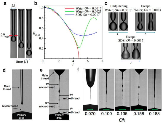
Figure 5.
(a–c) An experiment carried out by Kamat et al. showed that end-pinching could be precluded in nearly inviscid filaments with the presence of surfactants by breaking up the process of the viscous glycerol-water thread (d) without and (e) with surfactant; (f) breakup shapes of glycerol-water thread loaded with sodium dodecyl sulfate (SDS) (concentration = 1.5 cmc) as a function of Oh. Reproduced with permission from References [66,68].
3.4. Addition of Polymer to the Ink
Besides surfactant, the polymer is another kind of additive. It has long been demonstrated by many researchers [69,70,71,72,73,74,75,76] that the addition of long-chain macromolecules, even at low concentrations, can dramatically affect the breakup of liquid jets. The addition of polymers will give the ink some viscoelasticity and transform the ink from Newtonian fluids to non-Newtonian fluids [75,77], which normally exhibit complex behavior, such as shear thinning or strain hardening either in shear-dominated or extension-dominated flows, or both. Many researchers have demonstrated that the viscoelasticity of the ink could reduce the formation of satellites. However, the concentration of the polymers must be restricted to ensure printability. A small amount of polymer will turn the Newtonian fluid into the low viscosity elastic liquids [75], which can effectively suppress the satellite droplet formation during ejection (see Figure 6a,b). Excess polymer concentrations will lead to the formation of an extremely long filament, as shown in Figure 6c, which will result in the main drops failing to detach and can even be drawn back towards the nozzle [69,70,78].

Figure 6.
(a) Image sequence of drop formation for 50% glycerol/50% water created by a 50 V pulse with 79 µs between each frame. (b) Image sequence of drop formation for a non-Newtonian solution (50 ppm of 300 k PEO in glycerol/water) created by a 50 V pulse amplitude with 79 µs between frames. (c) A too-high polymer concentration leads to the formation of extremely long ligaments; The vertical scale bar (right) is 1 mm long. Reproduced with permission from References [75,79].
Besides the polymers’ concentration, molecular weight is another crucial factor determining the “jettability printability” threshold [72,74]. It had been confirmed by Hoath et al. [79] that the threshold concentration for jetting varies with molecular weight.
Bazilevskii et al. [70] studied the breakup of jets of viscoelastic fluids in DOD inkjet printing. They found that the polymers can prevent the formation of satellite drops at low concentrations. In 2012, Hoath et al. reported another strategy for suppressing the satellite droplets by using a shear-thinning aqueous solution of PEDOT:PSS [80]. This solution exhibits low viscosity within the printing nozzle over a wide range of jet speeds and rapidly recovers a higher viscosity once the jet has formed, preventing satellite formation. The typical morphology of the drops containing polymer during the ejection process is shown in Figure 6c. The mechanism of satellite suppression by polymers is that the elasticity of the solution will cause the fluid in the thread retracts into either the primary drop of the nozzle rather than breaking into satellite droplets [74,80,81,82,83]. The diagram shown in Figure 1 no longer applies to the polymer’s added inks since it does not consider the viscoelasticity of the ink.
3.5. Adoption of Super-Ink-Phobic Nozzles Plate
Normally, an ink film of about 10 nm will be formed on the nozzle plate during the printing process [52] (de Jong et al., 2007) due to the ink-philic nature of the nozzle plate. Although extremely thin, this film is unwelcome since dirt particles can be transported on it toward the nozzle, resulting in the non-axisymmetrical ejection. A recent investigation carried out by Yang et al. [29] showed that the nozzle plate’s ink-philic nature also contributes to the formation of the satellite droplets. The superhydrophobic nozzle can accelerate the pinch-off of the droplet from the nozzle by enhancing the Rayleigh–Plateau instability of filament at the breakpoint, as shown in Figure 7. Therefore, this feature results in a short ligament whose length is too short to pinch off satellite droplets [31]. This technique enables printing a wide range of inks (1 < Z < 38) without satellites. The superhydrophobic nozzle will decrease the size of the droplets ejected. This strategy is similar to dispensing small droplets by superhydrophobic needle nozzles [84] since less contact area between the thread and nozzle can significantly reduce the adhesion force.
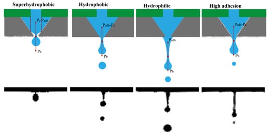
Figure 7.
Mechanical analysis for the drop pinch-off and the corresponding experimental result for the superhydrophobic, hydrophobic, and hydrophilic nozzles and the superhydrophobic nozzle with high adhesion. Reproduced with permission from Reference [29].
4. Satellite Droplets Utilizing Strategies
4.1. Satellite Droplets Printing
The recollection of satellites by the main droplets can also be regarded as one method for utilizing the satellites. This has been extensively investigated in the field of both DOD inkjet and CIJ [85]. Exclusively utilizing satellite droplets for printing was recently developed by Zhang et al. [86], named satellite droplets printing (SDP). As illustrated in Figure 8, a metal rod with a similar diameter is mounted opposite the orifice at a distance comparable to the orifice diameter. Instead of ejecting the liquid out to form free droplets, a much lower voltage is applied to the micro piezo to generate a meniscus connecting the orifice and the oppositely arranged rod. The breakup of the meniscus will generate a satellite droplet and is carried by a gas stream to the printing substrate. This strategy can achieve extremely high printing resolution using the femtoliter volume satellite, which is otherwise impossible for traditional inkjet printing.
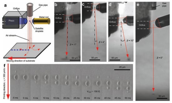
Figure 8.
Illustration of satellite droplet printing. (a) Schematic setup; (b–e) images taken during printing with different settings; (f) drops printed on the glass. Reproduced with permission from Reference [86].
In 2018, Zhang et al. proposed another satellite utilizing a strategy based on a double-orifice technique [87]. Satellite is generated by controlling the breakup of the meniscus formed between the two oppositely arranged orifices, as shown in Figure 9. Then, the pinched-off satellite droplets were directed to the substrate by applying an electric field between the orifices and the substrate. This technique is similar to the SDP technique they previously proposed in the aspect of satellite generation mechanisms. The main difference is that the double-orifice dispenser can work in liquid environments. Technically, this double-orifice technique cannot regard as a printing technique since it can only work at a frequency below 1 Hz. It would be more appropriate to classify it into the dispensing technique.
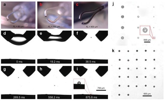
Figure 9.
Utilization of satellite droplets in a liquid environment by the double-orifice technique. (a–c) The double-orifice dispensers with different radii Ro; (d–i) electrical manipulation of the microdroplets after dispensing, with an initial volume of the meniscus of 833 nL, a drainage rate of approximately 16.7 L/s, and a voltage applied between the dispenser and the substrate of 300 V; (j) patterns of the suspension droplets, where the emulsion used was the same as that in Figure 2e; (k) water droplet patterns. Reproduced with permission from Reference [87].
4.2. Daughter Droplets Printing (Inkjet Printing in the Liquid Environment)
Usually, the inkjet printing technique can only work in a gaseous environment. In 2016 Zhang et al. demonstrated that it also could work in a liquid environment which is immiscible with the ink in the nozzle, but with a different droplet dispensing and manipulating mechanism [88]. Traditional inkjet printing generates the drops by squeezing the liquid out of a small orifice similar to the drops. Zhang et al. reported that instead of squeezing the liquid out, small daughter droplets could also be dispensed advantageously from large orifices by draining the liquid out of a drop suspended from a nozzle [88] as shown in Figure 10. In this work, the extrusion and retraction of the liquid were realized by a small syringe, which cannot work at a frequency for realized printing.
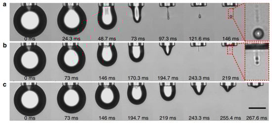
Figure 10.
Daughter droplet formation due to draining the liquid out of a drop suspended from a nozzle. Three regimes of droplet formation exist corresponding to the drainage rate Q. Droplet formation at various (a) Q = 7.2 nL s−1 (regime A, one main droplet), (b) Q = 2.46 nL s−1 (regime B, multiple droplets of similar sizes) and (c) Q = 1.96 nL s−1 (regime C, no droplet formation). Scale bar, 50 μm. Reproduced with permission from Reference [88].
In 2018, Zhang et al. [89] introduced the traditional piezo inkjet nozzle into a liquid environment and found it also can work with the same droplet generation mechanisms but much higher firing frequency (comparative to the firing frequency in the air). In this case, a relatively low driven voltage was applied to the piezo to ensure the oscillation of the pendent drops at the orifice. After dispensing, the daughter droplet was almost stagnant due to the inertia and viscosity of the carrier liquid. This is another difference with the drop ejection process in the air, during which the drop can get enough momentum to travel to the substrate. Therefore, additional actions must be taken to guide the stagnant droplet to the substrate. It can be an electric field [87,89] or a local flow field generated by the confined interface vibration [90,91]. Zhang et al. [89] demonstrated that the volume of the daughter droplets printed in a carrier liquid could be thousands of times smaller than those printed in the air using the same piezoelectric nozzle, opening possibilities for novel applications of the IJP technique.
It should be noted that although the daughter droplet dispensed by retracting the liquid out of the pendent is dropped into a liquid environment, it is several times smaller than the orifice. According to the definition of the satellite droplets, it cannot be classified into the satellite droplets family because there is no other droplet larger than it. Sometimes, the pinching of the neck might generate droplets much smaller than it. So, it was named daughter droplets, and the pendant drop was named the mother drop by Zhang et al. [88]. This naming scheme referred to the work of the researchers [9,10,11] who investigated the partial coalescence of drops at a liquid surface or interface; the drop initially settled on the surface or interface is named as mother drop, and the smaller pinched-off droplet is named as daughter droplets. At times, however, the smaller droplets pinched due to the partial coalescence of drops at the liquid surface or interface. These drops were also named satellite droplets by other researchers [3]. There are confusing definitions to explain satellite droplets and daughter droplets. Therefore, the utilization of daughter droplets was also included in this review.
5. Conclusions and Outlooks
Satellite droplets are the byproducts of drop ejection. Since the invention of the inkjet technique, numerous efforts have been made to eliminate or suppress the formation of satellite droplets, including recollection by the main drops, adjusting the waveform, addition of surfactant and polymers, and adoption of an ink-phobic nozzle plate. Satellite droplets can be effectively suppressed or eliminated by those strategies. However, the pinch-off and contraction mechanisms of inviscid, viscous, surfactant, and polymer-laden micron liquid thread still need to be thoroughly clarified for a deeper understanding of the satellite droplets formation mechanisms. The past 40 years have witnessed the inkjet printing technique’s born and fast development. Thanks to the MEMS technique, thousands of orifices can be integrated on a nozzle plate, and the droplet jetting frequency doubles every two years, following Moore’s law [92]. However, the size of the droplets does not see significant decrements within the past four decades. For the traditional inkjet, it is still impossible to print submicron features. The invention of satellite and daughter droplets printing might provide an effective way to significantly reduce the size of the droplets and improve the printing resolutions without reducing the orifice size. However, the satellite droplet printing (SDP) technique or daughter droplet printing is still at its early stage of development. Currently, they can only work with a single orifice nozzle. How to design and develop integrated nozzles for the SDP technique still faces many technical challenges. Efforts must be made to suppress or utilize the satellite droplets in the future.
Author Contributions
Conceptualization, Y.Z. and D.L.; methodology, Z.Y; software, G.Y.; validation, Y.Z., G.H. and D.L.; formal analysis, G.H.; investigation, Y.Z.; resources, Y.L.; data curation, J.W.; writing—original draft preparation, Y.Z.; writing—review and editing, Y.Z. and D.L.; visualization, G.Y.; supervision, Y.L.; project administration, Y.L.; funding acquisition, Y.Z. All authors have read and agreed to the published version of the manuscript.
Funding
This research was funded by the National Natural Science Foundation of China (Grant No. 52075548), the Taishan Scholar Program of Shandong Province (Grant No. tsqn201909068), the Fundamental Research Funds for the Central Universities (Grant No. 19 20CX06074A), the Science and Technology Support Plan for Youth Innovation of Universities in Shandong Province (Grant No. 2019KJB016), and the National Key Research and Development Program of China (Grant No. 2019YFE0105100).
Institutional Review Board Statement
Not applicable.
Informed Consent Statement
Not applicable.
Data Availability Statement
Data sharing not applicable.
Conflicts of Interest
The authors declare no conflict of interest.
References
- Stevenson, D.J. Origin of the moon-The collision hypothesis. Annu. Rev. Earth Planet. Sci. 1987, 15, 271–315. [Google Scholar] [CrossRef]
- Cameron, A.; Benz, W. The origin of the Moon and the single impact hypothesis IV. Icarus 1991, 92, 204–216. [Google Scholar] [CrossRef]
- Zhang, F.H.; Li, E.Q.; Thoroddsen, S.T. Satellite formation during coalescence of unequal size drops. Phys. Rev. Lett. 2009, 102, 104502. [Google Scholar] [CrossRef] [PubMed]
- Pan, K.; Chou, P.; Tseng, Y. Binary droplet collision at high Weber number. Phys. Rev. E 2009, 80, 36301. [Google Scholar] [CrossRef] [PubMed]
- Brenn, G.; Kolobaric, V. Satellite droplet formation by unstable binary drop collisions. Phys. Fluids 2006, 18, 87101. [Google Scholar] [CrossRef]
- Brenn, G.; Valkovska, D.; Danov, K.D. The formation of satellite droplets by unstable binary drop collisions. Phys. Fluids 2001, 13, 2463–2477. [Google Scholar] [CrossRef][Green Version]
- Tang, C.; Zhang, P.; Law, C.K. Bouncing, coalescence, and separation in head-on collision of unequal-size droplets. Phys. Fluids 2012, 24, 22101. [Google Scholar] [CrossRef]
- Rein, M. The transitional regime between coalescing and splashing drops. J. Fluid Mech. 1996, 306, 145–165. [Google Scholar] [CrossRef]
- Blanchette, F.; Bigioni, T.P. Partial coalescence of drops at liquid interfaces. Nat. Phys. 2006, 2, 254–257. [Google Scholar] [CrossRef]
- Thoroddsen, S.T.; Takehara, K. The coalescence cascade of a drop. Phys. Fluids 2000, 12, 1265–1267. [Google Scholar] [CrossRef]
- Charles, G.E.; Mason, S.G. The mechanism of partial coalescence of liquid drops at liquid/liquid interfaces. J. Colloid Sci. 1960, 15, 105–122. [Google Scholar] [CrossRef]
- Yarin, A.L. Drop impact dynamics: Splashing, spreading, receding, bouncing. Annu. Rev. Fluid Mech. 2006, 38, 159–192. [Google Scholar] [CrossRef]
- Xu, L.; Zhang, W.W.; Nagel, S.R. Drop splashing on a dry smooth surface. Phys. Rev. Lett. 2005, 94, 184505. [Google Scholar] [CrossRef] [PubMed]
- Josserand, C.; Zaleski, S. Droplet splashing on a thin liquid film. Phys. Fluids 2003, 15, 1650–1657. [Google Scholar] [CrossRef]
- Savart, F. Mémoire sur le choc d’une veine liquide lancée contre un plan circulaire. Ann. Chim. 1833, 54, 1833. [Google Scholar]
- Lenard, P. Ueber die schwingungen fallender tropfen. Ann. Phys. 1887, 266, 209–243. [Google Scholar] [CrossRef]
- van der Bos, A.; van der Meulen, M.; Driessen, T.; van den Berg, M.; Reinten, H.; Wijshoff, H.; Versluis, M.; Lohse, D. Velocity profile inside piezoacoustic inkjet droplets in flight: Comparison between experiment and numerical simulation. Phys. Rev. Appl. 2014, 1, 14004. [Google Scholar] [CrossRef]
- Shan, J.W.; Lang, D.B.; Dimotakis, P.E. Scalar concentration measurements in liquid-phase flows with pulsed lasers. Exp. Fluids 2004, 36, 268–273. [Google Scholar] [CrossRef]
- van der Bos, A.; Zijlstra, A.; Gelderblom, E.; Versluis, M. iLIF: Illumination by Laser-Induced Fluorescence for single flash imaging on a nanoseconds timescale. Exp. Fluids 2011, 51, 1283–1289. [Google Scholar] [CrossRef]
- Duineveld, P.C.; De Kok, M.M.; Buechel, M.; Sempel, A.; Mutsaers, K.A.; Van de Weijer, P.; Camps, I.G.; Van de Biggelaar, T.; Rubingh, J.J.; Haskal, E.I. Ink-Jet Printing of Polymer Light-Emitting Devices. In Proceedings of the Organic Light-Emitting Materials and Devices V, San Diego, CA, USA, 29 July–3 August 2001; SPIE: Bellingham, WA, USA, 2002; pp. 59–67. [Google Scholar]
- Kang, S.; Kim, S.; Sohn, D.K.; Ko, H.S. Analysis of drop-on-demand piezo inkjet performance. Phys. Fluids 2020, 32, 22007. [Google Scholar] [CrossRef]
- Stow, C.D.; Hadfield, M.G. An experimental investigation of fluid flow resulting from the impact of a water drop with an unyielding dry surface. Proc. R. Soc. London. A Math. Phys. Sci. 1981, 373, 419–441. [Google Scholar]
- Bhola, R.; Chandra, S. Parameters controlling solidification of molten wax droplets falling on a solid surface. J. Mater. Sci. 1999, 34, 4883–4894. [Google Scholar] [CrossRef]
- Derby, B. Inkjet printing of functional and structural materials: Fluid property requirements, feature stability, and resolution. Annu. Rev. Mater. Res. 2010, 40, 395–414. [Google Scholar] [CrossRef]
- Derby, B. Inkjet printing ceramics: From drops to solid. J. Eur. Ceram. Soc. 2011, 31, 2543–2550. [Google Scholar] [CrossRef]
- Reis, N.; Derby, B. Ink Jet Deposition of Ceramic Suspensions: Modeling and Experiments of Droplet Formation. MRS Online Proc. Libr. (OPL) 2000, 625, 117. [Google Scholar] [CrossRef]
- Tai, J.; Gan, H.Y.; Liang, Y.N.; Lok, B.K. Control of droplet formation in inkjet printing using Ohnesorge number category: Materials and processes. In Proceedings of the 2008 10th Electronics Packaging Technology Conference, Singapore, 9–12 December 2008; IEEE: Piscataway, NJ, USA, 2008; pp. 761–766. [Google Scholar]
- Yang, Q.; Li, H.; Li, M.; Li, Y.; Chen, S.; Bao, B.; Song, Y. Rayleigh instability-assisted satellite droplets elimination in inkjet printing. ACS Appl. Mater. Interfaces 2017, 9, 41521–41528. [Google Scholar] [CrossRef] [PubMed]
- Fromm, J.E. Numerical calculation of the fluid dynamics of drop-on-demand jets. IBM J. Res. Dev. 1984, 28, 322–333. [Google Scholar] [CrossRef]
- McKinley, G.H.; Renardy, M. Wolfgang von ohnesorge. Phys. Fluids 2011, 23, 127101. [Google Scholar] [CrossRef]
- Dong, H.; Carr, W.W.; Morris, J.F. An experimental study of drop-on-demand drop formation. Phys. Fluids 2006, 18, 72102. [Google Scholar] [CrossRef]
- Wijshoff, H. The dynamics of the piezo inkjet printhead operation. Phys. Rep. 2010, 491, 77–177. [Google Scholar] [CrossRef]
- Eggers, J. Nonlinear dynamics and breakup of free-surface flows. Rev. Mod. Phys. 1997, 69, 865. [Google Scholar] [CrossRef]
- Papageorgiou, D.T. On the breakup of viscous liquid threads. Phys. Fluids 1995, 7, 1529–1544. [Google Scholar] [CrossRef]
- Notz, P.K.; Basaran, O.A. Dynamics and breakup of a contracting liquid filament. J. Fluid Mech. 2004, 512, 223–256. [Google Scholar] [CrossRef]
- Xu, Q.; Basaran, O.A. Computational analysis of drop-on-demand drop formation. Phys. Fluids 2007, 19, 102111. [Google Scholar] [CrossRef]
- Day, R.F.; Hinch, E.J.; Lister, J.R. Self-similar capillary pinchoff of an inviscid fluid. Phys. Rev. Lett. 1998, 80, 704. [Google Scholar] [CrossRef]
- Mansour, N.N.; Lundgren, T.S. Satellite formation in capillary jet breakup. Phys. Fluids A Fluid Dyn. 1990, 2, 1141–1144. [Google Scholar] [CrossRef]
- Baker, G.R.; Meiron, D.I.; Orszag, S.A. Boundary integral methods for axisymmetric and three-dimensional Rayleigh-Taylor instability problems. Phys. D Nonlinear Phenom. 1984, 12, 19–31. [Google Scholar] [CrossRef]
- Pozrikidis, C. Boundary Integral and Singularity Methods for Linearized Viscous Flow; Cambridge University Press: Cambridge, UK, 1992. [Google Scholar]
- Eggers, J. Universal pinching of 3D axisymmetric free-surface flow. Phys. Rev. Lett. 1993, 71, 3458. [Google Scholar] [CrossRef]
- Brenner, M.P.; Lister, J.R.; Stone, H.A. Pinching threads, singularities and the number 0.0304. Phys. Fluids 1996, 8, 2827–2836. [Google Scholar] [CrossRef]
- Castrejón-Pita, J.R.; Castrejón-Pita, A.A.; Hinch, E.J.; Lister, J.R.; Hutchings, I.M. Self-similar breakup of near-inviscid liquids. Phys. Rev. E 2012, 86, 15301. [Google Scholar] [CrossRef]
- Fraters, A.; Jeurissen, R.; van den Berg, M.; Reinten, H.; Wijshoff, H.; Lohse, D.; Versluis, M.; Segers, T. Secondary tail formation and breakup in piezoacoustic inkjet printing: Femtoliter droplets captured in flight. Phys. Rev. Appl. 2020, 13, 24075. [Google Scholar] [CrossRef]
- Shi, X.D.; Brenner, M.P.; Nagel, S.R. A Cascade of Structure in a Drop Falling from a Faucet. Science 1994, 265, 219–222. [Google Scholar] [CrossRef] [PubMed]
- Shi, X.D.; Nagel, S.R.; Brenner, M.P. Iterated Instabilities during Droplet Fission. Phys. Rev. Lett. 1994, 73, 3391–3394. [Google Scholar] [CrossRef]
- Dijksman, J.F. Hydrodynamics of small tubular pumps. J. Fluid Mech. 1984, 139, 173–191. [Google Scholar] [CrossRef]
- Furlani, E.P.; Price, B.G.; Hawkins, G.; Lopez, A.G. Thermally induced Marangoni instability of liquid microjets with application to continuous inkjet printing. In Proceedings of the NSTI Nanotechnology Conference, Boston, MA, USA, 7–11 May 2006. [Google Scholar]
- Hu, Z.; Li, S.; Yang, F.; Lin, X.; Pan, S.; Huang, X.; Xu, J. Formation and Elimination of Satellite Droplets during Monodisperse Droplet Generation by Using Piezoelectric Method. Micromachines 2021, 12, 921. [Google Scholar] [CrossRef]
- Chen, A.U.; Basaran, O.A. A new method for significantly reducing drop radius without reducing nozzle radius in drop-on-demand drop production. Phys. Fluids 2002, 14, L1–L4. [Google Scholar] [CrossRef]
- Riefler, N.; Wriedt, T. Generation of monodisperse micron-sized droplets using free adjustable signals. Part. Part. Syst. Charact. 2008, 25, 176–182. [Google Scholar] [CrossRef]
- de Jong, J.; Reinten, H.; Wijshoff, H.; van den Berg, M.; Delescen, K.; van Dongen, R.; Mugele, F.; Versluis, M.; Lohse, D. Marangoni flow on an inkjet nozzle plate. Appl. Phys. Lett. 2007, 91, 204102. [Google Scholar] [CrossRef]
- Shao, X.; Duan, F.; Hou, Y.; Zhong, X. Role of surfactant in controlling the deposition pattern of a particle-laden droplet: Fundamentals and strategies. Adv. Colloid Interface Sci. 2020, 275, 102049. [Google Scholar] [CrossRef]
- Kim, D.; Rokoni, A.; Kaneelil, P.; Cui, C.; Han, L.; Sun, Y. Role of Surfactant in Evaporation and Deposition of Bisolvent Biopolymer Droplets. Langmuir 2019, 35, 12773–12781. [Google Scholar] [CrossRef]
- Eom, S.H.; Senthilarasu, S.; Uthirakumar, P.; Yoon, S.C.; Lim, J.; Lee, C.; Lim, H.S.; Lee, J.; Lee, S. Polymer solar cells based on inkjet-printed PEDOT:PSS layer. Org. Electron. 2009, 10, 536–542. [Google Scholar] [CrossRef]
- Sarchahi, H.; Maghrebi, M.; Baniadam, M. Inkjet printing of carbon nanotubes (CNTs) with a binary surfactant mixture: The effect of the nonionic surfactant on the uniformity of the printed surface. Diam. Relat. Mater. 2019, 100, 107550–107562. [Google Scholar]
- Venditti, G.; Murali, V.; Darhuber, A.A. Inkjet printing of surfactant solutions onto thin moving porous media. Colloids Surf. A Physicochem. Eng. Asp. 2022, 634, 127832. [Google Scholar] [CrossRef]
- Hanyak, M.; Darhuber, A.A.; Ren, M. Surfactant-induced delay of leveling of inkjet-printed patterns. J. Appl. Phys. 2011, 109, 74905. [Google Scholar] [CrossRef]
- Kamarudin, S.F.; Jaafar, M.; Abd Manaf, A.; Takamura, Y.; Masuda, T.; Yumoto, Y. Performance Enhancement of Inkjet Printed Multi-Walled Carbon Nanotubes Inks using Synthetic and Green Surfactants. Adv. Mater. Technol. 2021, 6, 2001026. [Google Scholar] [CrossRef]
- Franses, E.I.; Basaran, O.A.; Chang, C. Techniques to measure dynamic surface tension. Curr. Opin. Colloid Interface Sci. 1996, 1, 296–303. [Google Scholar] [CrossRef]
- Zhang, X.; Harris, M.T.; Basaran, O.A. Measurement of dynamic surface tension by a growing drop technique. J. Colloid. Interface Sci. 1994, 168, 47–60. [Google Scholar] [CrossRef]
- Basaran, O.A.; DePaoli, D.W. Nonlinear oscillations of pendant drops. Phys. Fluids 1994, 6, 2923–2943. [Google Scholar] [CrossRef]
- Zhang, X.; Basaran, O.A. An experimental study of dynamics of drop formation. Phys. Fluids 1995, 7, 1184–1203. [Google Scholar] [CrossRef]
- Javadi, A.; Krägel, J.; Pandolfini, P.; Loglio, G.; Kovalchuk, V.I.; Aksenenko, E.V.; Ravera, F.; Liggieri, L.; Miller, R. Short time dynamic interfacial tension as studied by the growing drop capillary pressure technique. Colloids Surf. A Physicochem. Eng. Asp. 2010, 365, 62–69. [Google Scholar] [CrossRef]
- Schmid, C. Formulation and properties of waterborne inkjet inks. In The Chemistry of Inkjet Inks; Publishing Co. Pte. Ltd.: Singapore, 2009; pp. 123–140. [Google Scholar]
- Kamat, P.M.; Wagoner, B.W.; Castrejón-Pita, A.A.; Castrejón-Pita, J.R.; Anthony, C.R.; Basaran, O.A. Surfactant-driven escape from endpinching during contraction of nearly inviscid filaments. J. Fluid Mech. 2020, 899, A28. [Google Scholar] [CrossRef]
- Yang, L.; Bain, C.D. Liquid jet instability and dynamic surface tension effect on breakup. In Proceedings of the NIP & Digital Fabrication Conference, Springfield, VA, USA, 2009; Society for Imaging Science and Technology, 2009; pp. 79–82. [Google Scholar]
- Kamat, P.M.; Wagoner, B.W.; Thete, S.S.; Basaran, O.A. Role of Marangoni stress during breakup of surfactant-covered liquid threads: Reduced rates of thinning and microthread cascades. Phys. Rev. Fluids 2018, 3, 43602. [Google Scholar] [CrossRef]
- Morrison, N.F.; Harlen, O.G. Viscoelasticity in inkjet printing. Rheol. Acta 2010, 49, 619–632. [Google Scholar] [CrossRef]
- Bazilevskii, A.V.; Meyer, J.D.; Rozhkov, A.N. Dynamics and breakup of pulse microjets of polymeric liquids. Fluid Dyn. 2005, 40, 376–392. [Google Scholar] [CrossRef]
- Chilcott, M.D.; Rallison, J.M. Creeping flow of dilute polymer solutions past cylinders and spheres. J. Non-Newton. Fluid Mech. 1988, 29, 381–432. [Google Scholar] [CrossRef]
- De Gans, B.J.; Duineveld, P.C.; Schubert, U.S. Inkjet printing of polymers: State of the art and future developments. Adv. Mater. 2004, 16, 203–213. [Google Scholar] [CrossRef]
- Goldin, M.; Yerushalmi, J.; Pfeffer, R.; Shinnar, R. Breakup of a laminar capillary jet of a viscoelastic fluid. J. Fluid Mech. 1969, 38, 689–711. [Google Scholar] [CrossRef]
- Hoath, S.D.; Hutchings, I.M.; Martin, G.D.; Tuladhar, T.R.; Mackley, M.R.; Vadillo, D. Links between ink rheology, drop-on-demand jet formation, and printability. J. Imaging Sci. Technol. 2009, 53, 41208. [Google Scholar]
- Shore, H.J.; Harrison, G.M. The effect of added polymers on the formation of drops ejected from a nozzle. Phys. Fluids 2005, 17, 33104. [Google Scholar] [CrossRef]
- Tuladhar, T.R.; Mackley, M.R. Filament stretching rheometry and breakup behaviour of low viscosity polymer solutions and inkjet fluids. J. Non-Newton. Fluid Mech. 2008, 148, 97–108. [Google Scholar] [CrossRef]
- Entov, V.M.; Hinch, E.J. Effect of a spectrum of relaxation times on the capillary thinning of a filament of elastic liquid. J. Non-Newton. Fluid Mech. 1997, 72, 31–53. [Google Scholar] [CrossRef]
- Meyer, J.D.; Bazilevsky, A.V.; Rozhkov, A.N. Effects of polymeric additives on thermal ink jets. Seattle, WA 1997. [Google Scholar]
- Hoath, S.D.; Harlen, O.G.; Hutchings, I.M. Jetting behavior of polymer solutions in drop-on-demand inkjet printing. J. Rheol. 2012, 56, 1109–1127. [Google Scholar] [CrossRef]
- Hoath, S.D.; Jung, S.; Hsiao, W.; Hutchings, I.M. How PEDOT: PSS solutions produce satellite-free inkjets. Org. Electron. 2012, 13, 3259–3262. [Google Scholar] [CrossRef]
- Clasen, C.; Eggers, J.; Fontelos, M.A.; Li, J.; McKinley, G.H. The beads-on-string structure of viscoelastic threads. J. Fluid Mech. 2006, 556, 283–308. [Google Scholar] [CrossRef]
- Clasen, C.; Phillips, P.M.; Palangetic, L.; Vermant, A.J. Dispensing of rheologically complex fluids: The map of misery. AIChE J. 2012, 58, 3242–3255. [Google Scholar] [CrossRef]
- Song, Y.; Fang, K.; Ren, Y.; Tang, Z.; Wang, R.; Chen, W.; Xie, R.; Shi, Z.; Hao, L. Inkjet printable and self-curable disperse dyes/P (St-BA-MAA) nanosphere inks for both hydrophilic and hydrophobic fabrics. Polymers 2018, 10, 1402. [Google Scholar] [CrossRef]
- Dong, Z.; Ma, J.; Jiang, L. Manipulating and dispensing micro/nanoliter droplets by superhydrophobic needle nozzles. ACS Nano 2013, 7, 10371–10379. [Google Scholar] [CrossRef]
- Fagerquist, R.L.; Yang, Q. Continuous Ink Jet Printing with Satellite Droplets. U.S. Patent US20070291058A1, 20 December 2007. [Google Scholar]
- Zhang, Y.; Li, D.; Liu, Y.; Wittstock, G. Printing with Satellite Droplets. Small 2018, 14, 1802583. [Google Scholar] [CrossRef]
- Zhang, Y.; Zhu, B.; Wittstock, G.; Li, D.; Liu, Y.; Zhang, X. Generating ultra-small droplets based on a double-orifice technique. Sens. Actuators B Chem. 2018, 255, 2011–2017. [Google Scholar] [CrossRef]
- Zhang, Y.; Zhu, B.; Liu, Y.; Wittstock, G. Hydrodynamic dispensing and electrical manipulation of attolitre droplets. Nat. Commun. 2016, 7, 12424. [Google Scholar] [CrossRef] [PubMed]
- Zhang, Y.; Li, D.; Liu, Y.; Wittstock, G. Inkjet Printing in Liquid Environments. Small 2018, 14, 1801212. [Google Scholar] [CrossRef] [PubMed]
- Li, D.; Li, H.; Yang, G.; Wang, J.; Huang, B.; Wu, X.; Sun, Q.; Ma, C.; Liu, Y.; Zhang, Y. Subharmonic resonance and antiresonance characteristics for high-frequency confined interface vibration inkjet printing. Phys. Fluids 2022, 34, 32104. [Google Scholar] [CrossRef]
- Li, D.; Huang, B.; Cao, Y.; Han, M.; Wu, X.; Sun, Q.; Ma, C.; Zhao, L.; Liu, P.; Zheng, C. Confined interface vibration for femtoliter droplets generation and manipulation. Nano Sel. 2021, 2, 338–345. [Google Scholar] [CrossRef]
- Lohse, D. Fundamental Fluid Dynamics Challenges in Inkjet Printing. Annu. Rev. Fluid Mech. 2022, 54, 349–382. [Google Scholar] [CrossRef]
Publisher’s Note: MDPI stays neutral with regard to jurisdictional claims in published maps and institutional affiliations. |
© 2022 by the authors. Licensee MDPI, Basel, Switzerland. This article is an open access article distributed under the terms and conditions of the Creative Commons Attribution (CC BY) license (https://creativecommons.org/licenses/by/4.0/).