Article

Drying Biomass with a High Water Content—The Influence of the Final Degree of Drying on the Sizing of Indirect Dryers

1
Department of Energy Engineering, Faculty of Mechanical Engineering, Czech Technical University in Prague, Technicka 4, 16607 Prague, Czech Republic
2
Department of Industrial Engineering and Informatics, Faculty of Manufacturing Technologies, Technical University of Kosice, Bayerova 1, 080 01 Prešov, Slovakia
*
Author to whom correspondence should be addressed.
Processes 2022, 10(4), 739; https://doi.org/10.3390/pr10040739
Submission received: 11 March 2022 / Revised: 7 April 2022 / Accepted: 8 April 2022 / Published: 11 April 2022
(This article belongs to the Special Issue Advanced in Dewatering and Drying Processes)

Abstract

:
This article deals with the influence of the final drying degree of moist biomass used as fuel in a power or CHP plant on indirect dryer sizing. For a description of the drying process, experiments with wet bark containing approx. 50 wt% of water were carried out in a laboratory indirect dryer. A new parameter called drying effectivity was introduced, whose size varies according to the degree of biomass being dried. Its maximum value corresponds to the optimal biomass drying, when the relative size of the indirect dryer to evaporate the required mass of water from the biomass would be smallest. Based on the experimentally determined drying characteristics of wet bark, the optimal drying of 13 wt% of water content was evaluated. If the bark was dried to a lower water content, the required relative size and price of the dryer would increase. Similarly, drying a bark with water content above 31 wt% is not very advantageous because drying effectivity continues to increase rapidly at this stage, and the required relative size of the dryer therefore decreases.

1. Introduction

The use of bioenergy as a renewable energy source for heat and power generation continues to increase in importance as coal combustion reduces. In 2019, renewable energy accounted for 19.7% of the energy consumed in the EU-27 [1], and bioenergy, as the most widely used source, covered 57% of this share [2]. Bioenergy contributes to the EU’s energy security, as most is derived from local biomass production [3]. Biomass comes mainly from three sources: ligneous biomass, agriculture biomass and waste biomass, where ligneous biomass comprises the largest portion at approximately 70%. Examples are bark, saw dust or wood chips obtained from wood industries and forest management operations [2].
More and more small-scale biomass power plants have recently been constructed. The increasing use of biomass as a renewable source for energy purposes depletes the capacity of traditional high-quality forms such as dry wood, straw, etc. Shortages and the rising price of these fuels increases interest in the use of low-grade biomass, whose utilization is often complicated by high water content, and which was previously considered a waste material with disposal issues [4]. Furthermore, the quality of raw biofuels is often degraded by a higher water content, which reduces their calorific value and limits the efficiency of their application.
Nowadays, it is advantageous to use these materials despite their poorer operating parameters, or higher demands on pretreatment technology, should these factors be offset by the low cost of such materials [4]. Actual pieces of these kinds of biomass often possess non-uniform shapes and sizes and a high water content, which is affected by their origin and storage conditions [5]. Therefore, drying and dimensional unification are a suitable way to prepare optimal properties for the further energetic use of these materials [6,7].
Drying, as one of the suitable pretreatments of biomass for burning, improves its heating value and combustion efficiency, while reducing the required capacity of the boiler auxiliary equipment, and often lowering emissions and improving boiler operation [8,9]. Fuel pre-drying could significantly decrease the exergy loss in the combustion process. For equal heat exchange process in the boiler, the exergy efficiency could be increased by percentage points in comparison to conventional direct biomass usage in a power plant [10]. Moreover, pre-drying of biomass reduces the mass flow rate of fuel needed for the desired boiler output, which has an impact on fuel transport and storage, as well as the flow rate of combustion air and flue gas and the boiler size [8].
The aim of most industrial drying processes is to obtain a solid product of a desired quality at a minimum cost and a maximum throughput and to maintain these conditions consistently. Good quality implies that the product corresponds to a number of physical, chemical and biological parameters, each within specified limits [11]. The requirements for biomass drying before energy use are usually somewhat different. Since it is necessary to dry significant mass flows of biomass, it is usually not required to pay close attention to compliance with the exact conditions of the drying process, e.g., even a significant deviation from the optimal temperature or drying time does not necessarily mean excessive degradation of the product, similar to its not completely homogeneous final water content.
Modern drying systems could supply products with a high quality; however, these systems are often not only expensive, but also largely energy intensive, e.g., drying is the most energy- and time-consuming stage of the wood preparation process. Therefore, the main goal should be to manage the drying of significant mass and volume flows of material with the lowest energy intensity because thermal drying requires a large amount of power that accounts for up to 15% of all industrial energy consumption [6,11]. The most commonly used conventional dryers often operate at low thermal efficiency, typically between 25% and 50%, yet may also fall as low as 10% [11]. Therefore, it is crucial to find the optimum design and application of the drying process [6]. Different systems and drying methods always have to be evaluated individually for specific conditions and assignments [6]. These facts, along with an environmental perspective, force researchers to search for more effective ways of drying, such as modifications to the process, modernizing equipment, and waste heat recovery [12,13].
In general, industrial drying technologies can be divided into two basic categories—direct (convective) drying, where the drying medium is in direct contact with the material being dried, and indirect (conductive, contact) drying, where the heat for drying is supplied through a conductive wall separating the heated and drying spaces, so that the drying medium is not in direct contact with the material being treated [8,14].
Efforts to reduce the heat consumption for biomass drying before combustion leads to the application of indirect drying, which utilizes an external heat source [15]. No air or flue gas need to be used to support the drying process, which eliminates heat loss at the outlet of the dryer [8]. Therefore, this method possesses low heat consumption, which is close to the value of the internal latent heat of the evaporated water [15]. Another advantage is the gain of the waste vapor leaving the indirect dryer with a minimum of impurities, which may be easily utilized for external use, e.g., by suitable connection of indirect biomass dryer, the efficiency of a biomass fired steam power station or CHP plant can be significantly increased [16]. The integration of drying into the energy cycle enables a significant reduction in fuel consumption or replacement of high-quality kinds of biomass by low-grade sorts [16,17,18]. In addition, if the material contains dust particles, which is typically a case of low-grade biomass, there is a risk of fire. However, an indirect drying system for woody biomass, where the dried material is in direct contact with evaporated steam, is considered safe in the comparison with conventional air drying [19].
Ligneous biofuels may possess a high initial water content of 50 wt% to 65 wt% [20]. Factors such as storage duration, season, assortment and rain protection have a statistically significant influence on water content of woody biomass [21,22]. The water content of fresh wood chips is approximately 50 wt%, but this could vary between 66 wt% and 36 wt% according to storage conditions [21]. For efficient combustion, it would be appropriate to reduce the biomass moisture to a level of 10 wt% to 15 wt% [4]. At these water content levels, all the free water is dried and drying of the bound water occurs, which is controlled by the diffusivity of water vapor in the material; thus, the drying rate significantly reduces [23,24]. The requirement for a higher degree of pre-drying prolongs the drying time, which significantly increases the required dryer dimensions and energy consumption [14]. Water contents significantly lower than 18 wt% are known to increase the risk of dust explosions, as dust clouds may be ignited if oxygen is present [20]. In conventional drying systems (e.g., air drying), the water content of wooden material is commonly reduced from 50 wt% to 25 wt% [25].
Contact drying of biomass is not yet widely used. The basic rules for their design and the optimization of their operation are still lacking. The aim of this article is to determine the required size of a contact dryer for the drying of biomass in relation to the required water content before combustion in the boiler. The required dryer size is designed according to experimentally determined drying rates of wet bark sourced from outdoor storage and containing about 50 wt% of water.

2. Materials and Methods

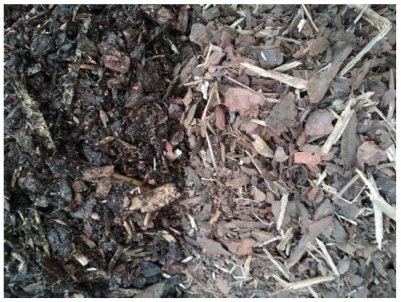
2.1. Tested Material

The tested material was a wet bark (see Figure 1) that was stored outdoors as a representative of waste material with high water content. This material was produced during wood processing by crushing the bark of spruce and pine trees, so it had a very inhomogeneous composition, and the particles varied considerably in shape and ranged in size from one millimeter to a few centimeters. The thickness of the particles ranged mostly from 3 to 5 mm. The bulk density was 330 kg/m3.
Fuel composition gained from laboratory analysis is given in Table 1. The water content in the raw biomass was around 50 wt%. As the wet bark was stored outdoors, its water content could vary over time. Therefore, the water content of the bark was determined by laboratory analysis at the beginning of each drying test.

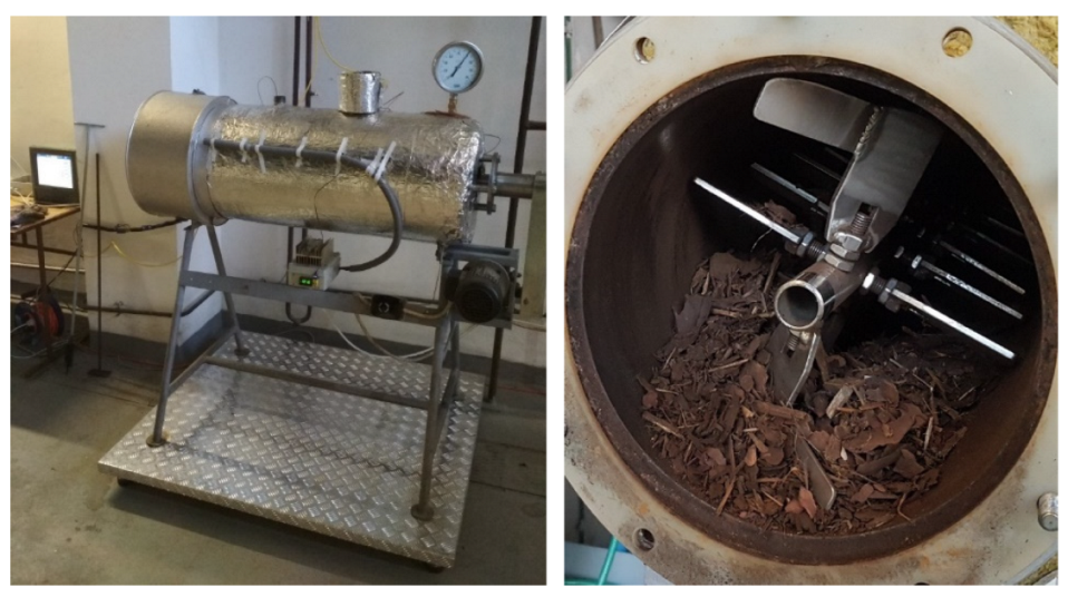
2.2. Experimental Dryer

The experimental dryer (see Figure 2) was designed as an indirect dryer in a paddle drum configuration. The dryer is electrically heated, thus allowing for a straightforward evaluation of energy consumption and temperature control with numerous settings to simulate various heat conditions, e.g., by hot water or low-pressure steam. It is presumed that the heat transfer in the drying process is not dependent on the way the heat is supplied because the thermal resistance between the heating medium, the conducting wall and the thermal resistance across the conducting wall are negligible compared to the resistance between the wall and the surface of the drying material and the resistance across its layer. Assuming sufficient material mixing, it is possible to compare different concepts of indirect dryers, regardless of their method of heating.
The drum of the experimental dryer has an inner diameter of 0.256 m and a length of 1 m. It works in a batch mode. The material inside the drum is mixed by paddle wheel stirrer with a rotation speed of 18 rpm. The drum volume is 0.051 m3, and the heated surface area of the drum is 0.81 m2.
The dryer is placed on a tensometric scale, which monitors the decrease in weight of the material during the drying process with accuracy of 0.002 kg. Five thermocouples are embedded in the wall of the dryer to measure the temperature of the heating surface. Two other thermocouples measure the temperature inside the dryer and the temperature of the exhaust vapor at the dryer outlet, which flows out into the surrounding by pipes in the upper part of the dryer due to small overpressure developing inside the dryer by the generated vapor.

2.3. Experiment Evaluation

At the beginning of each measurement, the initial weight of the batch and the water content in the bark were determined. The variation in the water content of the bark during drying, along with the drying rate, were continuously evaluated according to the weight loss of the dryer, which corresponds to the amount of evaporated water. The drying process could then be indicated by a drying curve defining the dependence of the actual water content in the bark on the drying time, as is usual.

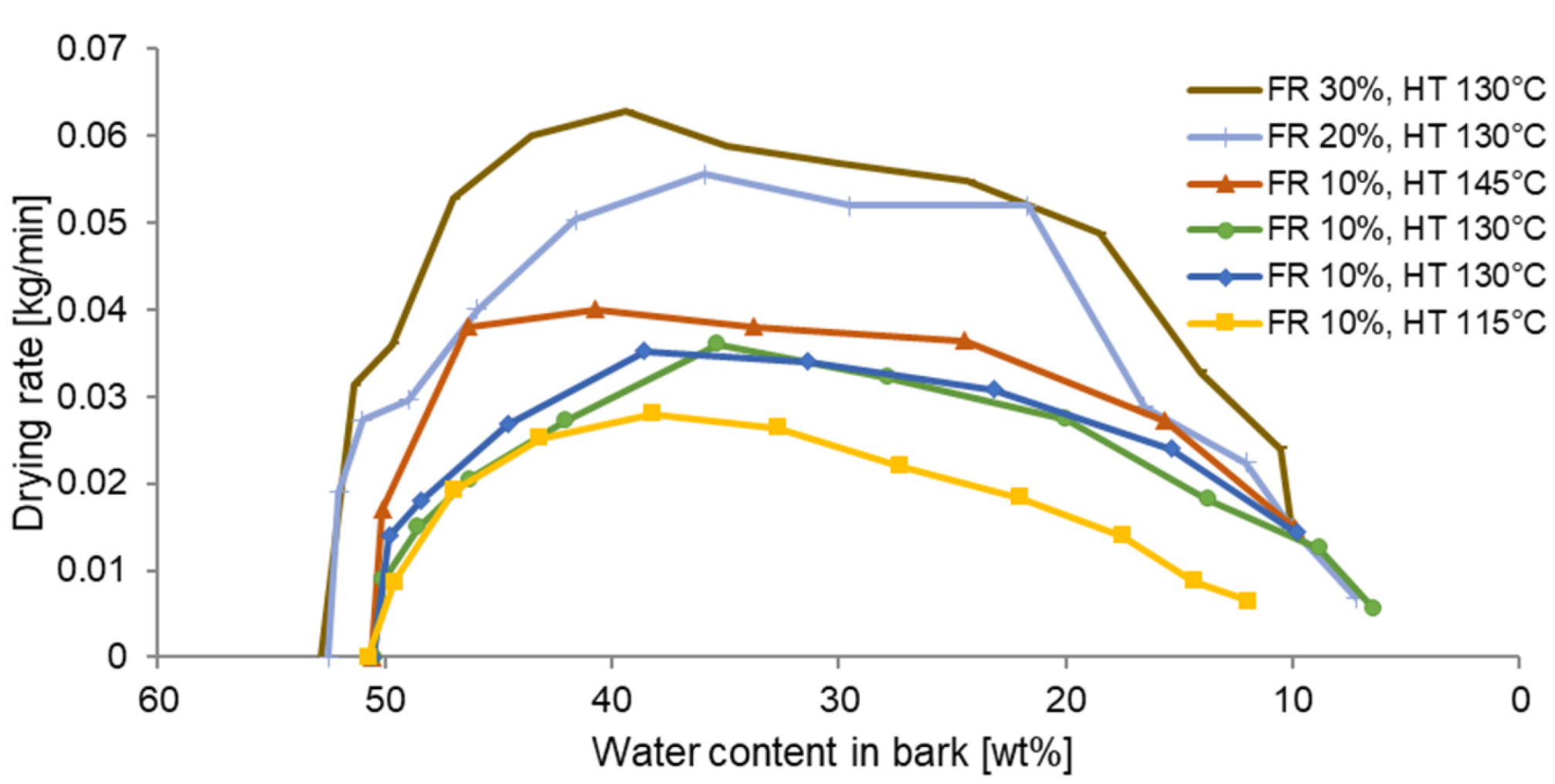
2.4. Determination of Drying Rate

Due to the continuous record of weight loss of the dried bark, it was possible to evaluate the change in drying rate during each experiment. The drying rate D R expresses the weight of dried water from the material in 1 min and its instantaneous value changes during drying.

2.5. Determination of the Required Dryer Size

For the design of dryers where the material is dried from the initial water content W 0 to the final water content W 1 , it is necessary to use the mean value of the drying rate for the residence time of the material in the dryer. The mean drying rate D R ¯   can be derived from the integral for instantaneous drying rate as a function of water content W in the drying interval between the water contents of W 0 and W 1 .
D R ¯ = 1 ( W 1 W 0 ) W 0 W 1 D R ( W ) d W
The square evaporation capacity E C defines the mass flow of evaporated water from dried material per 1 m2 of dryer-heated area and drying time. The evaporation capacity can be derived from the mean drying rate in a given drying interval related to the heated surface of the dryer A d r y e r .
E C = D R ¯ A d r y e r
The heated area of dryer A d r y e r required for the drying of a mass flow of bark M f u e l can be calculated based on the experimentally determined evaporation capacity corresponding to the analyzed drying interval from W 0 to W 1 and the mass flow of evaporated water M W .
A d r y e r = M W E C = W · M f u e l E C
The mass of water evaporated from drying of 1 kg of bark W is determined by the following equation.
W = W 0 W 1 1 W 1

3. Results and Discussion

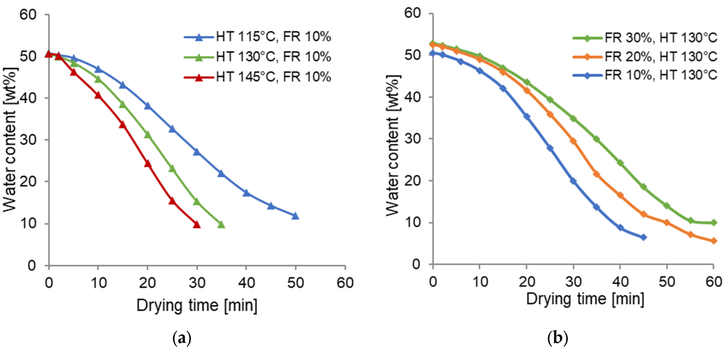
3.1. Results of Drying Tests

To describe the drying process in a wide range of operating conditions, the effects of different heating temperatures and dryer filling ratios (expressed as the volume of dried material to the dryer volume) on the drying characteristics were tested. In Figure 3, drying curves that describe the drying process for the various dryer heating temperatures (HT) and dryer filling ratios (FR) are shown.
The tested material was taken from the outdoor storage, and the input water content varied slightly depending on weather conditions.
If the filling ratio increases, more material is being dried, and the drying time increases. At the same time, the drying rate increases due to the larger contact area of the heated surface with a dried material.

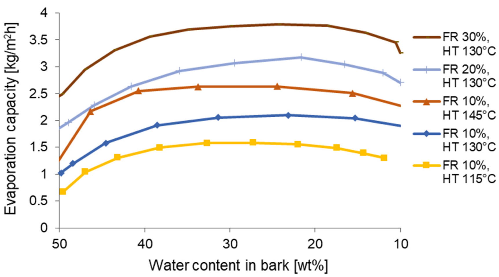
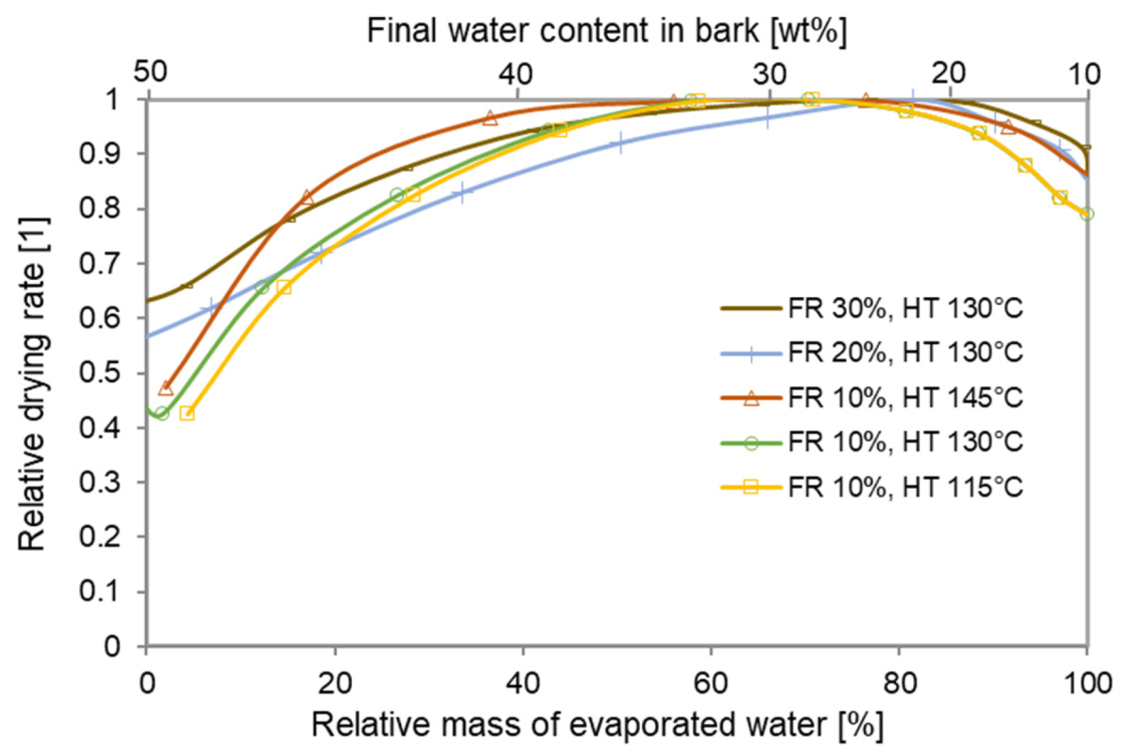
3.2. Evaluation of Drying Rates

The course of drying rates was obtained by evaluating the weight of the dried material as a function of the drying time. To eliminate the fluctuation of the instantaneous drying rate, its value was calculated as an average over a period of 5 min. The courses of instantaneous drying rates for drying of wet bark from 50 wt% to 10 wt% water content under different conditions are shown in Figure 4. The drying tests differed in the heating temperature HT from 115 °C to 145 °C and in the dryer volume filling ratio of dryer FR from 10% to 30%.
The change in drying intensity during the drying process corresponds to the three periods described in [14]. The lower initial drying rate increases steeply to its maximum value, which is related to the heating of the material to the drying temperature. Then the drying rate begins to decrease gradually and, in the final stage, when the material is relatively dry and only a small amount of vapor is released, the drying rate is at its lowest. The final drying phase is therefore not very intense and has little benefit in improving the conditions for burning the bark.
According to [14], the value of the overall heat transfer coefficients between the heating surface and the drying material for this type of indirect dryer can be assumed to be around 50 W/m2K. This value of the overall heat transfer coefficient can be derived from experimental values using the main drying rate for atmospheric drying by multiplying by the latent heat of evaporated water and dividing by the dryer surface and the temperature difference between the heated surface and material being dried. The values determined in this way range from 40 to 67 W/m2K, and they are in agreement with the value given in [14].
The process of indirect drying has been experimentally investigated in previous research works; however, these experiments were performed with laboratory material as sand or ceramic particles with a spherical shape and small dimensions. Some works focused on the research of the heat transfer coefficient (HTC) between the heated wall and bed of material in an indirect drum dryer. The value of the HTC for quartz sand with a mean particle diameter of 0.2 mm and mixing with a rotational speed of 6 rmp achieved 300 W/m2K [26], and for glass beads with a diameter of 2 mm it achieved 100 W/m2K [27]. For a rotational speed of 20 rmp and silica sand with a diameter of 1 mm, the HTC was 200 W/m2K, and it was 80 W/m2K for glass beads with a diameter of 4 mm [28]. These results show a strong dependence of the HTC on particle size. For larger particle sizes, they correspond with the experimental results given above.
The similarity of the course of measurements FR 10% and HT 130 °C (blue and green lines) confirms the repeatability of the experiment.

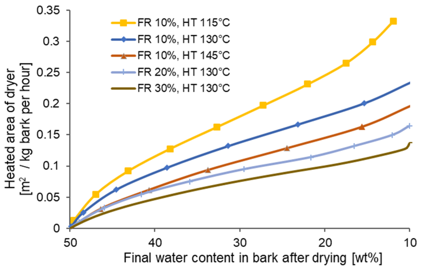
3.3. Effect of Final Degree of Drying on the Size of the Dryer

Based on the procedure described above, the evaporation capacities for various final degree of drying were determined according to Equations (1) and (2). The square evaporation capacity evaluated from the experimental data (see Figure 5) was calculated according to the mean drying rate in the drying interval from W 0 = 50 wt% to W 1 = ( 50 ,   10 wt% divided by the heated surface of the experimental dryer A e x p .
For comparison with other studies, only results for other materials are available. In [29], the drying rates of granulated porous aluminum silicate particles (diameter of 4.3 mm) were measured in a disc dryer with indirect heating with magnetic stirrer. The shapes of drying rates correspond with Figure 4. The values of the evaporation capacity (EC) for a rotational speed of 60 rpm ranged from 1 to 3 kg/m2h for atmospheric drying. The EC for hygroscopic peat in a tray dryer [30] with HT of 130 °C and a mixer speed of 40 rpm for particles with diameters from 0.75 mm to 6 mm achieved a value from 8 to 17 kg/m2h. Agitated contact drying of sewage sludge in a continuous paddle dryer was performed in [31], and the EC achieved the values up to 18 kg/m2h for HT of 160 °C and a stirrer speed of 42 rpm. The results in [32] for grained ceramic material (AlSi) with a diameter of 1.1 mm pertain to the paddle dryer after vacuum conditions with a revolution speed of 30 rpm. For the temperature difference between the saturation temperature corresponding with vacuum pressure and the heating temperature from 23 to 79 °C, the EC ranged from 5 to 16 kg/m2h. Achieving higher values of the EC for smaller particles is again evident here. Furthermore, good agreement with the experimental results is obtained assuming larger particle sizes of the bark.
The required size of the dryer heating area in the dependence on final water content for 1 kg per hour of dried bark evaluated from experiments under various drying conditions is shown in Figure 6.
After the first drying phase, where the heating of the material takes place at the same time, the drying process begins to be stable, and the size of the dryer increases linearly up to the final water content about 20 wt%. With further reduction of the water content, the required dryness size begins to increase progressively.
The required size of the dryer decreases both with increasing temperature of the heating medium and with increasing filling of the dryer. It can be said that filling has a greater effect. For indirect dryers, the main thermal resistance in the heat transfer process is between the wall and the surface of the bed of the drying material and the resistance across the bed of the drying material [14]. Assuming sufficient material mixing, there should also be similarity for different concepts and operating mode (batch or continuous) of indirect dryers [33].

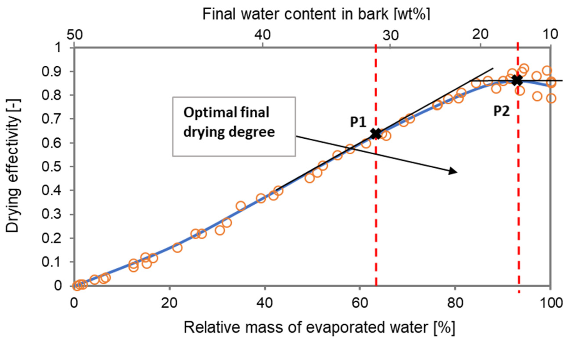
3.4. The Drying Process Effectivity

Relative expression of the analyzed parameters was introduced for the general evaluation of the drying process effectivity.
The relative drying rate represents the ratio of the mean drying rate D R ¯ in given drying intervals from W 0 = 50 wt% to W 1 = ( 50 ,   10 wt% up to the maximum value of the mean drying rate D R ¯ m a x within intervals from W 0 = 50 wt% to W 1 = 10 wt% determined by each experiment. In other words, D R ¯ m a x corresponds to the period in Figure 4, at which the largest amount of water is dried between the inlet water content W 0 = 50 wt% and the required final water content W 1 .
relative   D R = D R ¯ D R ¯ m a x
Analogously, the relative mass of evaporated water W represents the ratio of the mass of water evaporated from the fuel in a given drying interval to the total mass of water evaporated W m a x when drying the bark from 50 wt% to 10 wt% of water content.
relative   W = W W   m a x
In this way, the values of each analyzed parameter were divided by their maximum values, and the obtained relative expression was then plotted as a function of the relative mass of evaporated water.
The dependence of the relative drying rates and the relative mass of evaporated water on the final water content in the bark is shown in Figure 7. The curves of the relative drying rates for all the drying experiments were plotted as a linear increase in the relative mass of evaporated water. Their highest values lie in the middle of the drying interval. With a higher value of the relative drying rate, a smaller size of dryer is needed to evaporate the same amount of water from the fuel.
The drying effectivity D E is introduced as the product of the relative mass of evaporated water and the relative drying rate.
D E = relative   W · relative   D R
The curves of individual drying rates in Figure 7 have a very similar course; in absolute values they differ slightly in the initial and final stages. Thus, it is possible to use the average relative drying rate to express the drying effectivity and to calculate its generalized dependence on the relative mass of evaporated water during drying, independent of the process conditions. The result is shown in Figure 8. The differences in the course of individual drying effectivities for different drying conditions are evident in a water content of 20 wt%; nevertheless, the maximum values of the courses are located in the similar values of final water contents.
The drying effectivity steeply increases to a value of output water content around 31 wt%, from when the gradient of the curve begins to decrease (point P1 expressed by the tangent on the curve in Figure 8), and then from the value around 13 wt%, it starts to decrease (point P2 expressed as a maximal value of the curve in Figure 8).
Based on the obtained results, it is possible to determine the optimal final water content in the dried fuel, when the drying process would be at its most effective and when the relative size of the dryer for evaporating the required mass of water would be the smallest. According to the obtained experimental data, the optimal water content in the bark dried in the contact dryer is 13 wt%. If the bark was dried to a lower water content, the required relative size and price of the dryer would increase. Similarly, drying to a bark water content above 31 wt% is not very advantageous because the drying effectivity continues to grow rapidly at this stage and the required relative size of the dryer decreases.

4. Conclusions

Drying of the moist biomass before combustion is advantageous in order to improve combustion and increase boiler efficiency. A higher degree of drying brings a greater benefit but requires a larger and more expensive dryer.
The effect of the final drying degree of wet biomass on the required size of the indirect dryer was analyzed. To determine the rate of the drying process, experiments with wet bark containing approximately 50 wt% of water were carried out in a laboratory indirect dryer. The term drying effectivity was introduced for the general evaluation of the full course of the drying process. Based on drying experiments, the dependence of drying effectivity on the relative mass of evaporated water corresponding to the final biomass drying degree was determined. Depending on the biomass drying degree, the drying efficiency first increases, reaches its maximum value and then begins to fall. In this way, it is possible to determine the optimal drying of biomass, when the drying effectivity will be at its maximum and when the relative size of the dryer to evaporate the required amount of water would be the smallest. Based on the experimentally determined drying characteristics of the wet bark, the optimal drying at 13 wt% of water content was evaluated. It can also be concluded that drying above 31 wt% of water content in the bark proves fairly disadvantageous due to the fact that, at this stage, the drying effectivity continues to increase rapidly and the required relative size of the dryer decreases.
The results of the analysis show that it is not advantageous to dry the material to too low a water content in the dried material, because the required size of the dryer grows progressively, and the benefit obtained is small. The described procedure can be used to determine the optimal degree of drying for any material with regard to the effective use of the considered indirect dryer.
Future work will focus on the integration of the dryer into the biomass power plant and the evaluation of the optimal drying of biomass before combustion for the operation of the whole energy system. If the dryer is integrated into the energy plant, the benefits of drying for other equipment, especially for the efficiency and operation of the boiler, must be considered, and it is necessary to include the economic aspect in the evaluation. Only in this way will it be possible to determine the economically optimal drying degree of the fuel before combustion.

Author Contributions

Conceptualization, J.H., T.D. and J.P.; methodology, J.H. and T.D.; formal analysis, J.H.; investigation, J.H.; data curation, J.H.; writing—original draft preparation, J.H.; writing—review and editing, T.D. and J.P.; supervision, T.D. and J.P.; funding acquisition, T.D. All authors have read and agreed to the published version of the manuscript.

Funding

This work was supported by the Ministry of Education, Youth and Sports under OP RDE grant number CZ.02.1.01/0.0/0.0/16-019/0000753 “Research Centre for Low-Carbon Energy Technologies”.

Institutional Review Board Statement

Not applicable.

Informed Consent Statement

Not applicable.

Data Availability Statement

Not applicable.

Acknowledgments

The article was also written as a result of the successful solving of the Project of the Slovak Research and Development Agency under the contract No. APVV-15-0602.

Conflicts of Interest

The authors declare no conflict of interest.

References

  1. Eurostat. Renewable Energy Statistics. 2020. Available online: https://ec.europa.eu/eurostat/statistics-explained/index.php?title=Renewable_energy_statistics (accessed on 15 November 2021).
  2. Bioenergy Europe. Available online: https://bioenergyeurope.org/article/301-bioenergy-europe-s-new-brochure-we-are-renewable-energy-champions.html (accessed on 12 November 2021).
  3. Scarlat, N.; Dallemand, J.; Taylor, N.; Banja, M. Brief on Biomass for Energy in the European Union; Publications Office of the European Union: Luxembourg, 2019. [Google Scholar] [CrossRef]
  4. Ross, C. Biomass Drying and Dewatering for Clean Heat & Power; NorthWest CHP Application Center: Olympia, WA, USA, 2008. [Google Scholar]
  5. Jirjis, R. Storage and drying of wood fuel. Biomass Bioenergy 1995, 9, 181–190. [Google Scholar] [CrossRef]
  6. Murugan, P.; Dhanushkodi, S.; Sudhakar, K.; Wilson, V.H. Industrial and Small-Scale Biomass Dryers: An Overview. Energy Eng. 2021, 118, 435–446. [Google Scholar] [CrossRef]
  7. Kung, K.S.; Ghoniem, A.F. Multi-scale analysis of drying thermally thick biomass for bioenergy applications. Energy 2019, 187, 15989. [Google Scholar] [CrossRef]
  8. Wade, A. Report on Biomass Drying Technology; National Renewable Energy Laboratory: Golden, CO, USA, 1998. [Google Scholar]
  9. Van Loo, S.; Koppejan, J. The Handbook of Biomass Combustion and Co-Firing, 1st ed.; Earthscan: Sterling, VA, USA, 2008. [Google Scholar] [CrossRef]
  10. Liu, M.; Zhang, X.; Han, X.; Li, G.; Yan, J. Using pre-drying technology to improve the exergetic efficiency of bioenergy utilization process with combustion: A case study of a power plant. Appl. Therm. Eng. 2017, 127, 1416–1426. [Google Scholar] [CrossRef]
  11. Gebreegziabher, T.; Oyedun, A.; Hui, C. Optimum biomass drying for combustion—A modeling approach. Energy 2013, 53, 67–73. [Google Scholar] [CrossRef]
  12. Liu, Y.; Aziz, M.; Kansha, Y.; Bhattacharya, S.; Tsutsumi, A. Application of the self-heat recuperation technology for energy saving in biomass drying system. Fuel Process. Technol. 2014, 117, 66–74. [Google Scholar] [CrossRef]
  13. Wallin, E.; Fornell, R.; Räftegård, O.; Walfridson, T.; Benson, J. Design and Integration of Heat Recovery in Combination with Solar and Biomass-based Heating in a Drying Plant. Chem. Eng. Trans. 2020, 81, 1387–1392. [Google Scholar] [CrossRef]
  14. Mujumdar, A. Handbook of Industrial Drying, 3rd ed.; CRC/Taylor & Francis: Boca Raton, FL, USA, 2007. [Google Scholar] [CrossRef]
  15. Fagernäs, L.; Brammer, J.; Wilén, C.; Lauer, M.; Verhoeff, F. Drying of biomass for second generation synfuel production. Biomass Bioenergy 2010, 34, 1267–1277. [Google Scholar] [CrossRef]
  16. Havlik, J.; Dlouhy, T. Integration of Biomass Indirect Dryers into Energy Systems. J. Chem. Eng. Jpn. 2017, 50, 792–798. [Google Scholar] [CrossRef]
  17. Wang, J.; Salman, C.; Wang, B.; Li, H.; Thorin, E. Integrating sludge drying in biomass fueled CHP plants. Energy Ecol. Environ. 2021, 6, 1–12. [Google Scholar] [CrossRef]
  18. McIlveen-Wright, D.; Huang, Y.; Rezvani, S.; Redpath, D.; Anderson, M.; Dave, A.; Hewitt, N. A technical and economic analysis of three large scale biomass combustion plants in the UK. Appl. Energy 2013, 112, 396–404. [Google Scholar] [CrossRef]
  19. Adamski, R.; Siuta, D.; Kukfisz, B.; Mitkowski, P.T.; Szaferski, W. Influence of process parameters in superheated steam drying on fire and explosion parameters of woody biomass. Fuel Process. Technol. 2021, 211, 106597. [Google Scholar] [CrossRef]
  20. Strömberg, B. Fuel Handbook; Värmeforsk Service AB: Stockholm, Sweden, 2006. [Google Scholar]
  21. Hofmann, N.; Mendel, T.; Schulmeyer, F.; Kuptz, D.; Borchert, H.; Hartmann, H. Drying effects and dry matter losses during seasonal storage of spruce wood chips under practical conditions. Biomass Bioenergy 2018, 111, 196–205. [Google Scholar] [CrossRef]
  22. Leoni, E.; Mancini, M.; Aminti, G.; Picchi, G. Wood Fuel Procurement to Bioenergy Facilities: Analysis of Moisture Content Variability and Optimal Sampling Strategy. Processes 2021, 9, 359. [Google Scholar] [CrossRef]
  23. Holmberg, A.; Wadsö, L.; Stenström, S. Water vapor sorption and diffusivity in bark. Dry. Technol. 2015, 34, 150–160. [Google Scholar] [CrossRef]
  24. He, X.; Wang, L. Experimental Determination and Modeling of Drying Process of Woody Biomass. IOP Conf. Ser. Earth Environ. Sci. 2020, 552, 012016. [Google Scholar] [CrossRef]
  25. Vandenbroek, R. Biomass combustion for power generation. Biomass Bioenergy 1996, 11, 271–281. [Google Scholar] [CrossRef]
  26. Herz, F.; Mitov, I.; Specht, E.; Stanev, R. Experimental study of the contact heat transfer coefficient between the covered wall and solid bed in rotary drums. Chem. Eng. Sci. 2012, 82, 312–318. [Google Scholar] [CrossRef]
  27. Herz, F.; Mitov, I.; Specht, E.; Stanev, R. Influence of operational parameters and material properties on the contact heat transfer in rotary kilns. Int. J. Heat Mass Transf. 2012, 55, 7941–7948. [Google Scholar] [CrossRef]
  28. Lybaert, P. Wall-particles heat transfer in rotating heat exchangers. Int. J. Heat Mass Transf. 1987, 30, 1663–1672. [Google Scholar] [CrossRef]
  29. Tsotsas, E.; Schlunder, E.U. Contact Drying of Mechanically Agitated Particulate Material in the Presence of Inert Gas. Chem. Eng. Process. Process Intensif. 1986, 20, 277–285. [Google Scholar] [CrossRef]
  30. Esotsas, E.; Metzger, T.; Gnielinski, V.; Schlünder, E.U. Drying of Solid Materials. In Ullmann’s Encyclopedia of Industrial Chemistry; Wiley-VCH Verlag GmbH & Co. KGaA: Weinheim, Germany, 2010; pp. 11–13. [Google Scholar] [CrossRef]
  31. Chen, S.; Wang, F.; Milhé, M.; Arlabosse, P.; Liang, F. Experimental and theoretical research on agitated contact drying of sewage sludge in a continuous paddle dryer. Dry. Technol. 2016, 34, 1979–1990. [Google Scholar] [CrossRef] [Green Version]
  32. Schlünder, E.U.; Mollekopf, N. Vacuum contact drying of free flowing mechanically agitated particulate material. Chem. Eng. Process. Process Intensif. 1984, 18, 93–111. [Google Scholar] [CrossRef]
  33. Havlík, J.; Dlouhý, T. Indirect Dryers for Biomass Drying—Comparison of Experimental Characteristics for Drum and Rotary Configurations. ChemEngineering 2020, 4, 18. [Google Scholar] [CrossRef] [Green Version]
Figure 1. Wet bark before and after drying.
Processes 10 00739 g001
Figure 2. Experimental paddle dryer located on a tensometric scale.
Processes 10 00739 g002
Figure 3. Comparison of drying curves for various (a) heating temperatures (HT) and (b) dryer filling ratios (FR).
Processes 10 00739 g003
Figure 4. The course of drying rates for various conditions.
Processes 10 00739 g004
Figure 5. Square evaporation capacities for drying to various final water content and under different process conditions.
Processes 10 00739 g005
Figure 6. Required heating surface of the dryer for drying 1 kg of bark with a water content of 50 wt% to various final water contents placed under different processing conditions.
Processes 10 00739 g006
Figure 7. The dependence of the relative drying rates on the relative mass of evaporated water for various conditions in the range of 50 to 10 wt% of water content in bark.
Processes 10 00739 g007
Figure 8. Dependence of the drying process effectivity in a range of 50 wt% to 10 wt%.
Processes 10 00739 g008
Table 1. Results of ultimate and proximate analyses of bark and calorific value of its combustible.
C dafwt%, daf51.75
H dafwt%, daf5.97
O dafwt%, daf41.82
S dafwt%, daf0.03
N dafwt%, daf0.43
Ash dbwt%, db2.8
Wwt%~50
HHV dafkJ/kg20,550
db: dry basis; daf: dry ash-free basis; W: water content; HHV: higher heating value.
Publisher’s Note: MDPI stays neutral with regard to jurisdictional claims in published maps and institutional affiliations.

