Abstract
To address the limitations of traditional analytical modeling in capturing complex surface topographies, this paper presents comprehensive research on the error sensitivity mechanism, loaded tooth contact analysis (LTCA), and load-bearing contact characteristics of curved face gears based on high-precision point cloud modeling. The primary objectives are threefold: (1) to establish a high-fidelity topological reconstruction framework using Non-Uniform Rational B-Splines (NURBS) to bridge the gap between discrete data and finite element analysis (FEA); (2) to reveal the inherent mechanical response and sensitivity mechanism to spatial installation misalignments; and (3) to evaluate the contact performance and transmission error fluctuations under operational loads. Specifically, an analytical discretization method is proposed for point cloud generation, followed by a dual-path validation system integrating “rigid tooth contact analysis (TCA)” and “loaded FEA”. The results demonstrate that the proposed reconstruction achieves a superior accuracy with a Root Mean Square Error (RMSE) of 2.2 × 10⁻³ mm. Furthermore, shaft angle error is identified as the dominant sensitivity factor affecting transmission smoothness and edge contact, exerting a more significant influence than offset and axial errors. Compared with existing research on arc-tooth and helical face gears, this work provides a more robust closed-loop verification for curved profiles, revealing that material elastic deformation increases transmission error amplitude by 10.1% to 17.2%. These insights offer a theoretical reference for the high-precision assembly and tolerance allocation of helicopter transmission systems.
MSC:
37M05
1. Introduction
Face gear drives are transmission mechanisms that utilize intersecting or staggered shafts. They feature high power splitting, high overlap ratio, and low axial installation error, making them a critical solution for helicopter main reducers and high-speed vehicle transmission systems. Distinct from face gears driven by spur or helical cylindrical pinions, the curved face gear pair—specifically driven by an involute spiral worm—transcends the spatial limitations of orthogonal axis transmission. This unique offset configuration allows for the adjustment of induced curvature and relative sliding velocity, thereby enhancing lubrication performance and scuffing resistance. Furthermore, its high contact ratio characteristic homogenizes load distribution, leading to significant improvements in both transmission smoothness and power density. Nevertheless, the geometric topology of this gear pair is extremely complex. In practical engineering applications, the coupling effects of assembly errors and elastic deformations pose substantial challenges to accurate modeling and performance prediction.
Regarding geometric design and precise modeling, Litvin et al. [1] established the foundational theory of face gear meshing. Building upon this, Feng et al. [2] and Zeng [3] developed mathematical models for offset configurations, analyzing the nonlinear influence of design parameters on tooth surface characteristics. To address the difficulties in representing complex surfaces, Peng [4] and Mo et al. [5] introduced parametric modeling and reconstruction techniques. Notably, Mo et al. [6] further introduced a new iterative method for calculating the time-varying meshing stiffness, emphasizing the necessity of high-fidelity tooth surface representation for accurate dynamic analysis. Other studies, such as the reverse design method proposed by Guo et al. [7], have also contributed to the optimization of modified surfaces. However, a significant research gap remains: while ideal geometric equations are well-developed, the high-fidelity transition from analytical discrete point clouds to topological reconstruction specifically for “curved” profiles is seldom addressed. As noted by Xu [8], traditional analytical methods struggle to interface directly with Finite Element Analysis (FEA), often leading to geometric distortions in numerical simulations, which severely limits the reliability of subsequent contact analyses.
In the realm of tooth contact analysis (TCA) and error sensitivity, Zhou [9], Ke [10], and Han et al. [11] employed simulations to reveal the effects of assembly errors on contact path deviation. In the field of error control, Weng [12] explored the error coupling characteristics, while Xu [13], Chu [14], Wu [15], and Song [16] verified that topological modification can effectively suppress transmission errors. Recently, Yan et al. [17] proposed a rapid computerized generation and deviation correction method for helical face gears based on the grinding worm process, providing a theoretical basis for managing complex enveloping constraints. Despite these advances, for the specific configuration of curved face gears driven by involute spiral worms, the spatial meshing behavior is significantly more intricate. The conventional theoretical wisdom that “face gears are insensitive to axial errors” requires rigorous re-examination for these complex curved profiles. The research motivation of this study, driven by the demand for ultra-high-precision helicopter transmissions, is to establish a robust pipeline that eliminates modeling artifacts and reveals the true physical mechanisms of directional error sensitivity.
Furthermore, sole reliance on rigid body analysis is insufficient to meet the demands of precision transmission prediction. Peng et al. [18] confirmed through loaded contact analysis that edge contact stress is a critical factor limiting service life. Similarly, studies by Lin [19] and Wei et al. [20] demonstrated that elastic deformation under load significantly alters the actual transmission error. To provide a standardized evaluation of these effects, Hochrein et al. [21] developed a nominal contact stress calculation method based on equivalent cylindrical gearing, bridging the gap between face gear geometry and ISO strength standards. Consequently, establishing a closed-loop verification system that integrates “geometric kinematic analysis” with “loaded mechanical simulation” is of paramount importance.
To address these challenges, this study establishes a systematic research framework characterized by ‘Analytical Discrete Reconstruction–Mechanism Revelation–Dual Verification.’ The technical roadmap of the proposed methodology is illustrated in Figure 1. The primary objectives and core contributions of this work are detailed as follows:
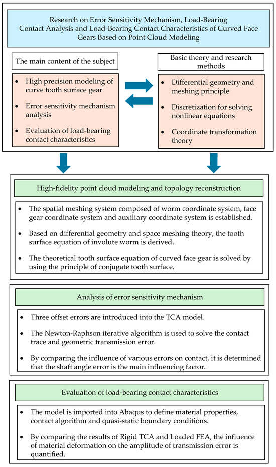
Figure 1.
Article technical route.
- Addressing the incompatibility between analytical methods and Computer-Aided Engineering (CAE) analysis, a modeling method based on Non-Uniform Rational B-Splines (NURBS) surface reconstruction is proposed. This resolves the geometric distortion of the spiral worm envelope surface and establishes a high-precision Computer-Aided Design (CAD) solid model.
- A numerical analysis model incorporating multi-axis errors is constructed to reveal the directional sensitivity laws of the gear pair.
- A closed-loop verification system combining “Rigid TCA” and “Loaded FEA” is established to analyze the discrepancies between transmission error curves under different load conditions.
The remainder of this paper is organized as follows: Section 2 establishes the mathematical model and analytical discretization of the curved face gear. Section 3 details the high-fidelity NURBS reconstruction and its accuracy evaluation. Section 4 investigates the error sensitivity mechanism through dual-path validation. Section 5 presents the loaded tooth contact analysis and comparative studies with existing research. Finally, Section 6 summarizes the conclusions and suggests future research directions.
2. Derivation of Tooth Surface Equations for Curved Face Gears
Precise mathematical description serves as the fundamental prerequisite for establishing high-fidelity solid gear models and conducting subsequent contact analyses. Generated by the enveloping process of an involute spiral worm under offset configurations, the geometry of a curved face gear is too intricate to be defined by conventional geometric parameters. Consequently, this section focuses on deriving the mathematical model utilizing differential geometry and spatial meshing theory. This derivation provides the sole mathematical foundation for the generation of discrete point clouds and the construction of complex solid models detailed in the subsequent section.
2.1. Spatial Coordinate Systems for Face Gear Meshing
As illustrated in Figure 2, coordinate systems and are rigidly attached to the involute spiral worm and the face gear, respectively. and are spatially fixed coordinate systems, denoting the initial positions of the worm and the face gear. and are employed as auxiliary coordinate systems to facilitate the matrix transformation operations. Consequently, the transformation matrix M21 from coordinate system to can be expressed as:
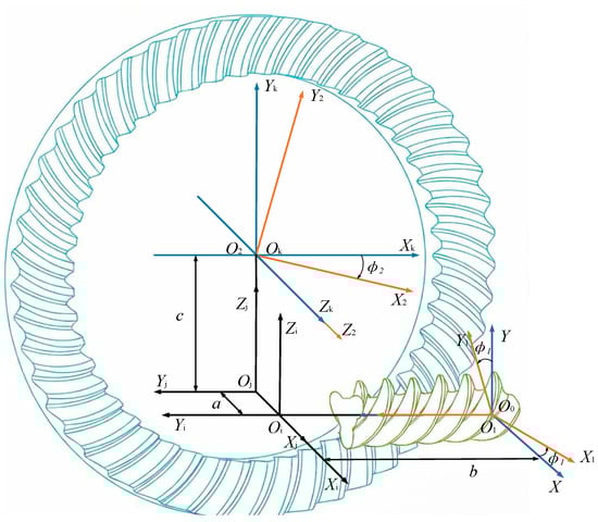
Figure 2.
Spatial coordinate systems of the curved face gear drive.
In the aforementioned Equation (1), represents the coordinate transformation matrix from coordinate system to . Specifically, and denote the transformations between the gear/worm-fixed systems and their respective initial positions; and are auxiliary transformations representing the spatial orientation; and describes the relative position between the worm and gear axes.
In the aforementioned equation, and denote the rotation angles of the involute spiral worm and the face gear, respectively. The symbols a, b, and e represent the gear mounting parameters, corresponding to the mounting height, axial mounting distance, and offset distance, respectively.
2.2. Tooth Surface Equations and Unit Normal Vectors of the Involute Spiral Worm
Based on the generation principle of face gears, the precision of the generated tooth surface is intrinsically linked to the geometric conformity between the cutting tool and the imaginary generating gear. Specifically, the closer the tool profile approximates that of the imaginary gear, the more accurate the resulting conjugated face gear surface will be.
Consequently, the derivation of the worm’s tooth surface equations constitutes the primary step. As illustrated in Figure 3, the axial cross-section of the involute spiral worm exhibits a standard involute profile. In this study, a left-handed worm is selected as the research object. Based on the involute equation and the generation principle of the helicoid, the tooth surface equations for the left flank (Side I) and the right flank (Side II) are derived as Equations (2) and (3), respectively:
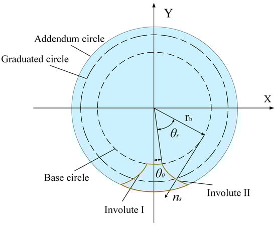
Figure 3.
Axial profile of the involute spiral worm.
In the equations above, , , and are the components of the vector in the Cartesian coordinate system, denotes the helical parameter, and represents the surface design parameter. is the angular parameter of a point on the involute profile, is the base circle radius of the involute worm, and corresponds to the angular parameter measured from the symmetry line of the worm tooth profile to the starting point of the involute.
The unit normal vector of the involute spiral worm is determined by the cross product of the partial derivatives of the surface vector, as expressed in Equation (4):
In Equation (4), denotes the unit normal vector of the worm tooth surface. The cross product in the numerator determines the normal direction, while the denominator performs the normalization to ensure has a unit magnitude for subsequent contact analysis.
2.3. Relative Velocity at the Meshing Point
When the tooth flank of the worm comes into contact with that of the face gear at an arbitrary meshing point, the relative velocity between the two conjugate surfaces is determined by [1]:
where and are the angular velocities of the involute spiral worm and the face gear, respectively. denotes the relative angular velocity between the two tooth surfaces; represents the position vector of an arbitrary point on the tool in coordinate system with respect to the origin ; while corresponds to the position vector of point in the fixed coordinate system . Consequently, the relative velocity at the meshing point can be derived as:
, , and denote the Cartesian components of the relative velocity vector for the left and right flanks.
2.4. Tooth Surface Equations of the Curved Face Gear
According to the theory of conjugate surfaces, the tooth flanks of the face gear and the worm must maintain continuous contact throughout the meshing process. This geometric constraint necessitates that both surfaces share a common tangent plane and a common normal vector at any instantaneous contact point. Consequently, the relative velocity vector at the contact point must be orthogonal to the common normal vector. Mathematically, this kinematic relationship is governed by the following equation of meshing:
Consequently, the meshing function describing the contact between the involute worm flank I (Side I) and the face gear tooth surface, as well as the meshing function for the worm flank II (Side II) and the face gear, can be derived as:
The tooth flank of the face gear is generated via the enveloping process of the worm. This generation characteristic dictates that any arbitrary point on the face gear’s surface must simultaneously satisfy two fundamental geometric constraints: first, it must comply with the equation of meshing derived for the worm-face gear pair; and second, it must maintain spatial coincidence with a corresponding point on the worm’s flank. Taking the coordinate system as the reference frame, the position vector of the corresponding point on the worm tooth surface can be expressed in as:
Specifically, when , the vector corresponds to the tooth flank I (Side I) of the face gear; conversely, when , denotes the tooth flank II (Side II). According to the principle of meshing, by simultaneously solving Equations (9) and (10) with Equation (11), the mathematical expressions for the two tooth surfaces of the face gear can be derived as follows:
In the preceding equations, , , and denote the left tooth flank (Side I) and the right tooth flank (Side II) of the face gear, respectively.
3. High-Precision Modeling of Curved Face Gears via Discrete Point Clouds
Although the tooth surface equations derived in the preceding section mathematically define the geometry, they are not directly applicable to general Finite Element Analysis (FEA). Given that the curved face gear is generated by the enveloping process of a spiral worm under offset configurations, it exhibits inherent nonlinearity and edge singularities. Consequently, traditional modeling approaches often suffer from geometric distortion, thereby compromising the accuracy of subsequent analyses. To address this, this section proposes a high-fidelity reconstruction methodology based on the framework of “Differential Derivation–Point Cloud Discretization–NURBS Surface Reconstruction,” effectively bridging the gap between the “analytical model” and the “solid model.” Specifically, a high-density point cloud dataset is first generated from the tooth surface equations. Subsequently, smooth and continuous solid surfaces are reconstructed using Non-Uniform Rational B-Splines (NURBS). Finally, a high-precision virtual assembly model satisfying the requirements of contact analysis is established.
Utilizing the conjugate tooth surface equations (Equations (12) and (13)) derived in Section 1 as the discretization targets, numerical calculations are performed based on the parameters listed in Table 1. Following the discretization flowchart illustrated in Figure 4, a high-density sampling grid is established within the parametric domain of the tooth surface. To account for the curvature mutations at the junction between the filet surface and the working flank, an adaptive step-size method is employed to solve for spatial coordinate sets satisfying the meshing conditions. This process yields the discrete point clouds for both the involute spiral worm and the face gear, as depicted in Figure 5.

Table 1.
Design parameters of the curved face gear drive system.
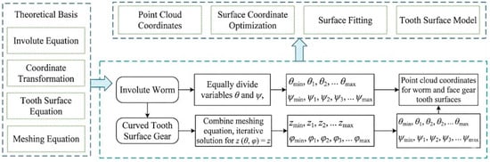
Figure 4.
Technical flowchart of the discretization process.
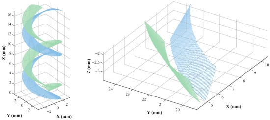
Figure 5.
Point clouds of the involute spiral worm and the face gear.
Simultaneously, to eliminate truncation errors induced by numerical iteration and to remove computational outliers, a rigorous filtering and refinement process was applied to the raw point cloud data. This step guarantees that the normal vectors of the point cloud maintain strict consistency with the theoretical normal vectors derived from the analytical equations.
In this study, the NURBS surface fitting method is employed to facilitate topological reconstruction, transitioning from “discrete points” to “continuous surfaces.” The NURBS technique is renowned for its robust capabilities in representing complex free-form surfaces. The specific reconstruction methodology proceeds as follows: Firstly, the purified point cloud data is imported into the 3D environment via the Initial Graphics Exchange Specification (IGES) standard data interface. Secondly, characteristic cross-sections are extracted along the face width direction to construct the tooth profile skeleton. Finally, smooth tooth surface patches are generated utilizing the lofting algorithm. As illustrated in Figure 6a, the resulting solid model of the curved face gear exhibits superior surface smoothness and curvature continuity. This approach effectively resolves common defects associated with traditional modeling methods, such as geometric fragmentation and ripple effects, thereby achieving high geometric fidelity. To quantitatively evaluate the modeling fidelity, a Cloud-to-Mesh signed distance analysis was conducted on 5453 analytical sampling points. As shown in the deviation heatmap in Figure 6b, the statistical results yield a mean distance of −2.0 × 10⁻⁴ mm and a Root Mean Square Error of 2.2 × 10⁻³ mm. Specifically, in the high-curvature regions like tooth filets emphasized by the reviewer, the errors remain uniform and extremely small, confirming that no geometric distortion or fitting instability occurs. This provides high-fidelity geometry for subsequent precision contact performance predictions.
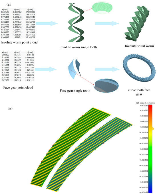
Figure 6.
(a) 3D modeling of the curved face gear pair. (b) Tooth surface error distribution diagram.
Based on the design parameters listed in Table 1, the virtual assembly of the gear pair is completed. To guarantee the precise spatial alignment between the two gears, coaxial and positioning constraints are strictly imposed.
The assembly model is illustrated in Figure 7. A static interference check confirms that there is no penetration interference in the theoretical meshing zone and no abnormal clearance in the non-working regions. This result validates the geometric accuracy of the point cloud modeling method and provides a reliable geometric foundation for the subsequent analysis.
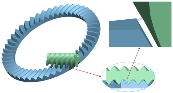
Figure 7.
Assembly and clearance inspection of the curved face gear pair.
4. Tooth Contact Analysis (TCA) Incorporating Assembly Errors and Sensitivity Mechanism
In practical engineering applications, the assembly of the gear pair is inevitably influenced by factors such as manufacturing tolerances, housing deformation, and bearing clearances. Furthermore, deviations in mounting positions are prone to inducing contact pattern shifts and edge contacts. Although traditional face gear theory suggests a tolerance to axial errors, its applicability to curved face gears characterized by high reduction ratios and large helix angles remains unverified. Consequently, this chapter establishes a mathematical TCA model incorporating assembly errors. By introducing offset error, axial error, and shaft angle error, this study aims to quantify the influence laws of different errors on contact traces and transmission errors, thereby revealing the error sensitivity mechanism of this gear pair and providing a theoretical reference for tolerance allocation.
4.1. Transmission Coordinate Systems and Transformation Matrices with Errors
To quantitatively describe the assembly errors, error degrees of freedom must be introduced into the ideal meshing coordinate system. The coordinate systems for TCA are established as shown in Figure 8. Here, coordinate systems and are rigidly attached to the worm and the face gear, respectively, while denotes the fixed coordinate system. Auxiliary coordinate systems , , , and are established to introduce the assembly errors of the face gear pair, where and represent the rotation angles of the worm (pinion) and the face gear, respectively.
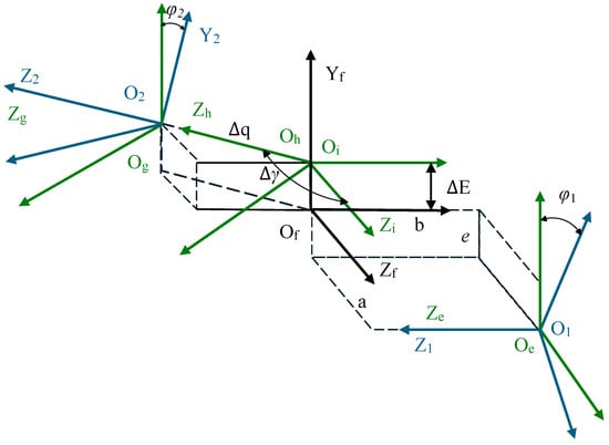
Figure 8.
Coordinate systems for tooth contact analysis considering assembly errors.
Within the fixed coordinate system , three independent spatial assembly errors are defined: the axial mounting error relative to along the negative Z2 direction, the offset mounting error ΔE along the negative Y2 direction, and the shaft angle error Δγ, representing the counter-clockwise rotation of about the Y2 axis. Regarding the sign conventions within , a deviation along the positive Y2 direction constitutes a positive offset error ; a deviation along the negative Z2 direction constitutes a positive axial error ; and a counter-clockwise rotation of the face gear about the Y2 axis denotes a positive shaft angle error .
Based on the theory of homogeneous coordinate transformation, the final transformation matrix from the spatial moving coordinate system to the spatial fixed coordinate system is derived as:
where denotes the coordinate transformation matrix, and are the rotation angles of the worm and the face gear in the contact coordinate system, respectively.
Similarly, the transformation matrix , mapping the spatial moving coordinate system to the fixed spatial coordinate system , is derived as:
where and represent the coordinate transformation matrix.
4.2. Numerical Solution Algorithm for Contact Traces and Transmission Errors
Considering that the curved face gear pair driven by an involute spiral worm primarily engages via Tooth Flank I (Side I) under standard forward transmission conditions, Tooth Flank I is selected as the subject for the subsequent TCA and error sensitivity analyses to simplify the investigation without loss of generality.
In the presence of assembly errors, to ensure that the two tooth surfaces maintain continuous contact, they must satisfy the geometric kinematic conditions of positional coincidence and normal vector collinearity at every instant. Specifically, within the fixed coordinate system , he position vectors of the two surfaces must coincide, and their unit normal vectors must be collinear. Consequently, a system of nonlinear equations is established as follows:
and is still the rotation angle of the worm and the face gear, but it needs to be recalculated later, so it is distinguished from the previous article.
The tooth surface equation of the involute cylindrical worm and its corresponding unit normal vector are expressed in the coordinate system as:
Analogously, the tooth surface equation of the curved face gear and its corresponding unit normal vector are expressed in the coordinate system as:
Equation (16) comprises three position equations and three normal equations. Since the magnitude of a unit normal vector is constantly unity, only two of the normal equations are independent. Consequently, the system constitutes a nonlinear system of five independent scalar equations with six unknown variables. To solve this underdetermined system, this paper selects the rotation angle of the worm, , as the input generalized coordinate. By discretizing into a series of constant-step nodes, the problem is transformed into a determinate solution problem for five unknowns.
The system of equations is solved numerically using the Newton-Raphson iterative algorithm. The Jacobian matrix is constructed to calculate the residual vector, and the contact point parameters are iteratively updated. The convergence criterion for the iteration is defined as a position residual δ < 10−5 mm. Specifically, given an initial input rotation angle , the contact parameters from the ideal error-free condition are used as the initial guess. By solving the equation system, the output rotation angle and the contact point parameters are obtained. Utilizing the solution from the previous step as the initial value for the subsequent step, the complete contact trajectory is traced progressively along the meshing path.
The geometric transmission error (TE) is defined as the deviation between the actual rotation angle and the theoretical rotation angle of the driven gear. Its mathematical expression is given by:
In the above equation, and represent the actual rotation angles of the pinion (worm) and the gear, respectively, and represent the number of teeth of worm and face gear, respectively, while and denote their corresponding initial rotation angles.
The physical significance of this index is the motion smoothness of the gear pair under the assumptions of zero load and rigid bodies. Its fluctuation amplitude and characteristics directly reflect the internal excitation of the transmission system, serving as a critical theoretical basis for assessing vibration and noise performance.
4.3. Numerical Analysis and Discussion of Error Sensitivity
Taking the previously established TCA mathematical model as the input, this section investigates the influence of spatial assembly errors on the transmission performance of the curved face gear. A controlled variable method is adopted: Tooth Flank I is selected as the research object. First, the benchmark characteristics under ideal conditions are determined. Subsequently, offset error, axial error, and shaft angle error are individually introduced to examine the drift patterns of the contact traces and the amplitude fluctuations of the geometric transmission errors (TE).
In the ideal state without assembly errors, the calculated results are illustrated in Figure 9.
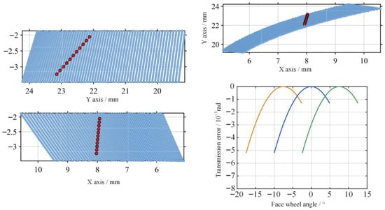
Figure 9.
Contact trace and transmission error of Tooth Flank I under ideal assembly conditions.
The results shown in Figure 9 indicate that the contact pattern is distributed in the central region of Tooth Flank I. This verifies the correctness of the conjugate tooth surface equations derived in Section 2. The transmission error curve exhibits a small-amplitude periodic parabolic fluctuation, with an amplitude of 0.79 × 10⁻³ rad, indicating that the gear pair maintains good kinematic smoothness under the rigid-body assumption.
After introducing an offset error of ±0.4 mm, the simulation results are shown in Figure 10.
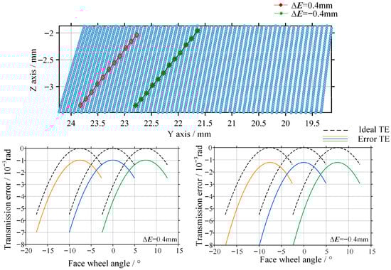
Figure 10.
Contact trace and transmission error of the gear pair with offset error.
The contact pattern mainly drifts along the face width direction. A positive offset error causes the contact region to shift toward the outer radius of the face gear, whereas a negative offset error drives the contact region toward the inner radius. Both the peak value and the amplitude of the transmission error increase with the magnitude of the offset error. However, overall, the contact region remains within the effective working tooth surface, and no severe geometric interference occurs.
As shown in Figure 11, the contact characteristics are further investigated when the axial position of the face gear varies by ±0.15 mm.
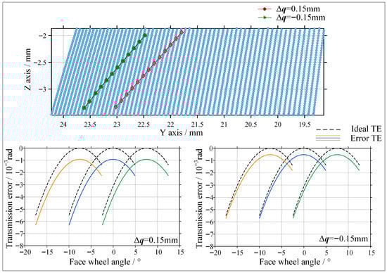
Figure 11.
Contact trace and transmission error of the gear pair with axial error.
The contact pattern mainly drifts along the face width direction. A positive axial error causes the contact region to shift toward the outer radius of the face gear, while a negative axial error drives the contact region toward the inner radius. However, compared with the offset error, the magnitude of the contact trace drift is relatively small. The amplitude of the transmission error curve increases in a gradual manner. These results indicate that the curved face gear inherits the advantage of conventional face gears, namely low sensitivity to axial misalignment. Therefore, in practical engineering assembly, the axial positioning tolerance can be appropriately relaxed to reduce assembly difficulty.
As shown in Figure 12, when a shaft angle deviation of ±0.1° is introduced, the transmission performance deteriorates severely.
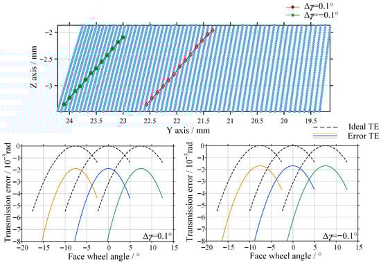
Figure 12.
Contact trace and transmission error of the gear pair with shaft angle error.
The contact path undergoes severe distortion. Under a negative shaft angle error, the contact pattern rapidly migrates toward the tooth edge, resulting in pronounced edge contact, which is highly likely to cause edge spalling or scuffing on the tooth surface under loaded conditions. Both the peak value and the amplitude of the transmission error increase dramatically, far exceeding those induced by offset error and axial error. This behavior arises because the surface normal of the involute spiral worm is extremely sensitive to angular variations, such that even a small shaft angle deviation can lead to a sharp instantaneous change in the transmission ratio.
Theoretical Investigation into the Mechanism of Directional Sensitivity The identified “directional sensitivity” is fundamentally determined by the distribution law of the induced normal curvature () across the tooth surface. A positive shaft angle error causes the mean contact point (MCP) to migrate toward the inner radius (small end) of the face gear. In this region, as discussed by Yan [17] regarding worm-generated helical face gears, the geometric constraints are more stringent due to the inherent spiral-enveloped topology. For our curved profile, this migration results in an exponential increase in , leading to a severe compression of the contact ellipse and localized stress concentration. This mechanism is rooted in the nonlinear curvature distribution inherent to the worm-driven enveloping kinematics and remains universally applicable regardless of specific parameter sets.
By comparing Figure 10, Figure 11 and Figure 12, it can be concluded that shaft angle error is the primary factor affecting the transmission accuracy of curved face gears. Therefore, in precision transmission design and assembly, shaft angle accuracy should be treated as the highest-priority control index.
5. Loaded Contact Analysis Based on the Finite Element Method
In the preceding sections, the theoretical kinematic behavior of the curved face gear pair was revealed through tooth contact analysis under the rigid-body assumption. However, in practical transmission processes, complex elastic mechanical behaviors inevitably exist. Neglecting material deformation may lead to deviations in the prediction of transmission accuracy. In particular, under working load conditions, tooth bending deformation and Hertzian contact deformation are superimposed on geometric errors, which may exert unknown influences on the theoretical transmission error curves.
Therefore, based on the NURBS solid model established in Section 3, a nonlinear finite element method is employed to perform loaded contact analysis. A dual verification framework of “rigid TCA–loaded FEA” is constructed. By comparing the morphology of the contact pattern with the theoretical contact trace obtained from TCA, the geometric accuracy of the solid model is validated. Furthermore, under loaded conditions, the sensitivity laws of transmission performance to spatial assembly errors are re-examined to assess the applicability of the error sensitivity conclusions derived from rigid TCA within a realistic physical field.
5.1. Establishment and Preprocessing of the Finite Element Model
To investigate the influence of elastic deformation on the transmission accuracy of curved face gears, a quasi-static contact analysis model is established in the Abaqus environment based on the high-precision NURBS solid model constructed in Section 3. The materials of both gears are defined as isotropic linear elastic materials. The material parameters are set as follows: elastic modulus E = 1.05 × 10⁵ MPa, Poisson’s ratio v = 0.33, and density 8.22 × 10⁻⁹ tonne/mm3.
Boundary conditions and loads are applied according to the working conditions. For the face gear, full constraints are imposed on the inner ring and bottom surface, with only the rotational degree of freedom about its axis released. A reference point is defined at the center of the worm axis, and a kinematic coupling constraint is applied to the inner bore surface. Only the rotational degree of freedom about the axis is released, with a rotational speed of 1 rad/S applied along with a torque of 10,000 N· mm (equivalent to 10 N·m).
A surface-to-surface contact discretization algorithm is adopted. The worm tooth surface, which exhibits higher stiffness, is defined as the master surface, while the face gear tooth surface is defined as the slave surface. A “hard contact” pressure–overclosure relationship is employed, allowing separation after contact. The penalty method is used, and the friction coefficient is set to 0.1. Due to the complex geometry of the involute spiral worm, C3D10M tetrahedral elements are employed for its meshing, while C3D8R hexahedral elements are used for the face gear.
During finite element-based transmission error analysis, the large number of incremental steps involved makes manual extraction of nodal angular displacement data inefficient and error-prone. Therefore, an automated post-processing script is developed using the Abaqus Python (2024) secondary development interface. The data processing procedure is as follows: the calculated. odb result file is loaded via the odb Access module; the history output variables of the reference points for the worm and face gear are identified; the rotational angle sequences corresponding to each time increment are extracted; and the loaded transmission error at each time step is calculated according to Equation (19), thereby obtaining the transmission error curve under load.
5.2. Contact Region and Transmission Error Based on Finite Element Analysis
As shown in Figure 12, the contact pattern under load exhibits an elliptical contact shape and is located in the central region of Tooth Flank I. CNAREA represents the contact area on the tooth flank. By comparing this contact pressure cloud with the contact trace obtained from the TCA results in Chapter 3 (Figure 9), it can be observed that the spatial position and contact orientation of the two results are highly consistent. This agreement verifies the high geometric accuracy of the point cloud-based modeling method proposed in Chapter 3 and further confirms that no geometric distortion occurs in the constructed curved surfaces.
As shown in Figure 13, The loaded transmission error curve obtained from FEA is compared with the theoretical curve derived from TCA within the same coordinate system. The two curves exhibit identical fluctuation periods and phases. The theoretical transmission error amplitude predicted by TCA is 0.79 × 10⁻³ rad, whereas the amplitude obtained from FEA is 0.87 × 10⁻³ rad, representing an increase of approximately 10.1%. This increment corresponds to the transmission lag component induced by material elastic deformation.
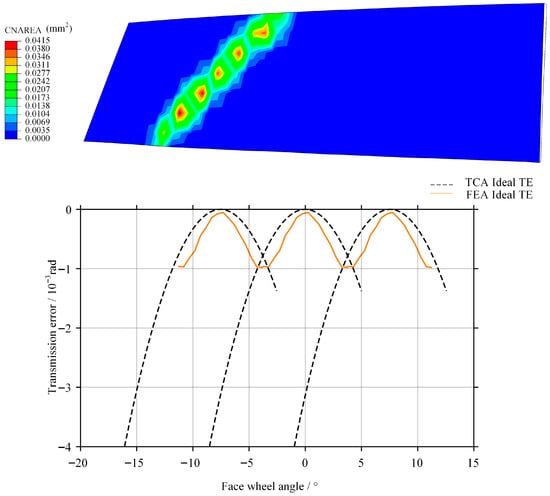
Figure 13.
Contact pattern and transmission error curve obtained by finite element analysis under standard assembly conditions.
The results indicate the negative influence of elastic deformation on transmission accuracy. Therefore, in precision transmission design, elastic correction factors should be superimposed on geometric error evaluations to achieve more accurate performance predictions.
As shown in Figure 14, after introducing offset error, the contact pattern exhibits a drift along the face width direction, which is consistent with the results obtained from TCA. When a positive offset error is introduced, the transmission error amplitude obtained from numerical TCA is 0.85 × 10⁻³ rad, while the amplitude obtained from finite element analysis is 0.98 × 10⁻³ rad, representing an increase of 15.3%. When a negative offset error is introduced, the transmission error amplitude predicted by TCA is 0.87 × 10⁻³ rad, whereas the corresponding finite element result reaches 1.02 × 10⁻³ rad, with an increase of 17.2%. These results are consistent with the conclusion drawn from the TCA that the system exhibits higher sensitivity to negative offset error.
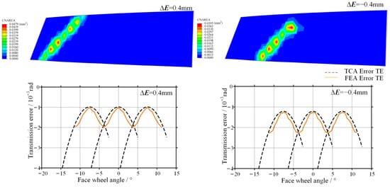
Figure 14.
Contact pattern and transmission error obtained by finite element analysis with offset error.
As shown in Figure 15, the contact characteristics under axial error are further investigated.
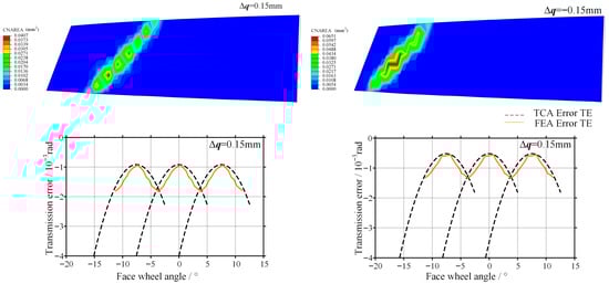
Figure 15.
Contact pattern and transmission error obtained by finite element analysis with axial error.
The contact pattern exhibits only a slight shift along the axial direction, and no edge stress concentration is observed. When a positive axial error is introduced, the transmission error amplitude predicted by numerical TCA is 0.80 × 10⁻³ rad, while the corresponding finite element result is 0.91 × 10⁻³ rad, representing an increase of 13.8%. When a negative axial error is introduced, the transmission error amplitude obtained from TCA is 0.81 × 10⁻³ rad, whereas the finite element result is 0.90 × 10⁻³ rad, with an increase of 11.3%. The deformation of the gear teeth alleviates potential contact impact, indicating that this configuration exhibits good adaptability to axial positioning errors.
As shown in Figure 16, when a small shaft angle deviation is introduced, the transmission performance deteriorates severely.
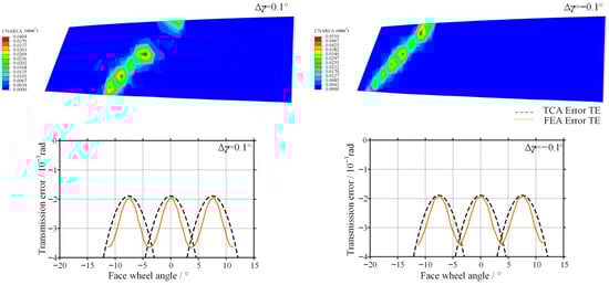
Figure 16.
Contact pattern and transmission error obtained by finite element analysis shaft angle error.
The contact pattern rapidly migrates toward the tooth edge, with the main contact regions concentrated near the tooth root and tooth tip, resulting in pronounced edge contact. This contact state may induce severe stress concentration at the tooth tip and root regions. When a positive shaft angle error is introduced, the transmission error amplitude predicted by numerical TCA is 1.68 × 10⁻³ rad, while the finite element result reaches 1.89 × 10⁻³ rad, corresponding to an increase of 12.5%. When a negative shaft angle error is introduced, the transmission error amplitude obtained from TCA is 1.48 × 10⁻³ rad, whereas the finite element result increases to 1.72 × 10⁻³ rad, representing an increase of 16.2%. The physical field simulations further confirm the conclusions drawn in Chapter 4, namely that shaft angle error is the primary factor affecting both transmission accuracy and load-carrying capacity. Moreover, positive shaft angle error exerts the most detrimental influence on the gear pair.
5.3. Comparative Analysis with Independent Research Models
To address the concern of “homologous consistency” and validate the engineering transferability of the conclusions, a comparative study was conducted using independent external references. As summarized in Table 2, the methodological pipeline of “analytical discretization—rapid contact analysis” employed in this study follows the advanced research paradigms established by Mo et al. (2022) [5] and Yan et al. (2024) [17]. While Mo et al. identified tooth thickness as the critical error for arc-tooth face gears, our results—together with the findings of Yan et al. on helical face gears—demonstrate that shaft angle and alignment errors dominate the transmission quality for worm-generated profiles. This external comparison confirms that the revealed sensitivity mechanisms are inherent to the specific gear geometry rather than artifacts of the modeling methodology.
Table 2.
Comparative analysis between the proposed model and independent research models.
6. Conclusions and Future Scope
6.1. Conclusions
To address the difficulty of converting complex enveloping equations into solid models and the incompatibility of analytical methods with CAE analysis, a high-precision modeling approach based on “differential geometry derivation–analytical point cloud mapping–NURBS reconstruction” is proposed. Through virtual assembly and interference inspection, this method is verified to effectively eliminate geometric distortion induced by spiral enveloping, achieving a high-fidelity transformation from a “mathematical model” to a “physical simulation model.” This approach provides a generalizable interface for the digital design of complex spatial gears.
The error sensitivity characteristics of the curved face gear drive are systematically investigated. Shaft angle error is identified as the dominant factor governing transmission accuracy degradation. Numerical TCA results reveal the strong directional dependence of the gear pair’s sensitivity on spatial assembly errors. Shaft angle error is confirmed to be the primary source leading to severe transmission error amplification and edge contact, whereas the proposed configuration inherits the favorable tolerance of conventional face gears to axial installation errors. Accordingly, shaft angle accuracy should be treated as the highest-priority control index in practical assembly processes.
The elastic lag effect is quantitatively characterized, and a closed-loop dual validation framework of “rigid TCA–loaded FEA” is established. The results demonstrate that under a load of 10 N · m, material elastic deformation leads to an increase in transmission error amplitude ranging from 10.1% to 17.2%, indicating that reliance on purely geometric theory would significantly underestimate system vibration. Therefore, elastic correction factors must be incorporated into precision transmission design. The high consistency between loaded contact patterns further verifies the correctness of the proposed modeling and geometric analysis methods. Meanwhile, the results confirm that elastic deformation can partially alleviate contact impact induced by axial misalignment, enhancing the assembly adaptability of this gear configuration under complex operating conditions.
6.2. Future Research Scope
Based on the current research, the following directions are proposed for future investigation:
- Active Topology Modification: Drawing on the mature local synthesis and tooth surface modification theories of spiral bevel gears, future work should focus on active topology design for curved face gears to pre-compensate for the identified shaft angle sensitivities.
- Dynamic Characteristics and NVH: Transitioning from quasi-static loaded contact analysis to full dynamic modeling is essential to evaluate the vibration and noise (NVH) characteristics of curved face gears under high-speed helicopter transmission conditions.
- Digital Twin and Closed-loop Manufacturing: The proposed point-cloud-based framework can be extended to develop a digital twin system for closed-loop manufacturing, enabling real-time compensation of machining errors by mapping measured deviations back to the machine tool settings.
Author Contributions
Methodology, R.G.; Software, R.G.; Validation, Q.L. and R.G.; Investigation, J.J. and C.T.; Resources, Q.Y.; Data curation, M.W.; Writing—original draft, R.G.; Writing—review & editing, Q.L. and C.Z.; Supervision, C.Z.; Project administration, Q.L. and C.Z.; Funding acquisition, Q.L. All authors have read and agreed to the published version of the manuscript.
Funding
This research received no external funding.
Data Availability Statement
The data presented in this study are available on request from the corresponding author due to laboratory confidentiality protocols.
Conflicts of Interest
The authors declare no conflict of interest.
References
- Litvin, F.L.; Fuentes, A.; Gonzalez-Perez, I.; Piscopo, A.; Ruzziconi, P. Face Gear Drive with Helical Involute Pinion: Geometry, Generation by a Shaper and a Worm, Avoidance of Singularities and Stress Analysis; NASA Glenn Research Center: Cleveland, OH, USA, 2005.
- Feng, Z.R.; Gao, L.F.; Fang, P.; Xiong, G.J.; Luo, C. Tooth surface design and solid modeling of offset orthogonal curvilinear face gear. J. Mech. Transm. 2021, 45, 92–96. (In Chinese) [Google Scholar]
- Zeng, X.Q. Study on Meshing Characteristics and Strength Analysis of Offset Worm Face Gear Transmission. Master’s Thesis, East China Jiaotong University, Nanchang, China, 2023. (In Chinese) [Google Scholar]
- Peng, X.Y. The Modeling Method and Contact Simulation of the Curved Tooth Face Gear; Tianjin University: Tianjin, China, 2013. (In Chinese) [Google Scholar]
- Mo, S.; Song, W.; Zhu, S.; Feng, Z.-Y.; Tang, W.-J.; Gao, H.-J. Complex geometric modeling and tooth contact analysis of a helical face gear pair with arc-tooth. J. Cent. South Univ. 2022, 29, 1213–1225. [Google Scholar] [CrossRef]
- Mo, S.; Song, W.; Zhang, Y.; Zhou, Y.; Yao, B.; Houjoh, H.; Zhang, W. A new iterative method for calculating the time-varying meshing stiffness of orthogonal face gear pairs. Mech. Mach. Theory 2025, 206, 105938. [Google Scholar] [CrossRef]
- Guo, H.; Wang, L.; Hou, Z.; Hua, C.; Zhou, C.; Hou, S. A reverse design method for small-modulus offset face gear based on optimized modified surface. Forsch. Ingenieurwesen 2025, 89, 93. [Google Scholar] [CrossRef]
- Xu, Y.Y. Research on Parametric Modeling and Contact Analysis of Spiral Bevel Gears. Master’s Thesis, Shenyang University of Technology, Shenyang, China, 2022. (In Chinese) [Google Scholar]
- Zhou, R.C.; Wu, W.M.; Feng, M.M.; Guo, H.; Lin, Y.H. Tooth Surface Generation and Meshing Characteristics Analysis of Low-angle Face Gear Drives. China Mech. Eng. 2023, 34, 631–640. (In Chinese) [Google Scholar]
- Ke, J. Simulation Analysis of Hourglass Worm Meshing Characteristics Based on TCA. Master’s Thesis, Xi’an Technological University, Xi’an, China, 2024. (In Chinese) [Google Scholar]
- Han, X.; Zhang, X.; Zheng, F.; Xu, M.; Tian, J. Mathematic model and tooth contact analysis of a new spiral non-circular bevel gear. J. Cent. South Univ. 2022, 29, 157–172. [Google Scholar] [CrossRef]
- Weng, D.Y.; Shen, Y.B.; Xu, W.J. Analysis of bearing contact characteristics of face gear coupled with assembly error. J. Mech. Transm. 2024, 48, 35–41. (In Chinese) [Google Scholar]
- Xu, J.H. Research on Modification Design and Meshing Performance of Face Gear Based on High Order Transmission Error. Master’s Thesis, Fuzhou University, Fuzhou, China, 2023. (In Chinese) [Google Scholar]
- Chu, L.Y.; Yang, J.J.; Han, Z.Y.; Wei, B.Y.; Tong, A.J.; Wang, D.F. Topological modification design method of face gear surface and tooth contact performance analysis. Mod. Manuf. Eng. 2023, 8, 108–114. (In Chinese) [Google Scholar]
- Wu, S.X. Research on Tooth Surface Correction and Modification Method of Heavy Duty Spiral Bevel Gears Machined by Duplex Helical Method. Ph.D. Thesis, Central South University, Changsha, China, 2022. (In Chinese) [Google Scholar]
- Song, W.H. Research on Modification Processing Method and Loaded Contact Characteristics of Face Gear. Master’s Thesis, Tiangong University, Tianjin, China, 2021. (In Chinese) [Google Scholar]
- Yan, Y.; Guo, H.; Gu, J.; Zhao, N.; Liu, L. Computerized generation, deviation correction and rapid tooth contact analysis of helical face gear. Mech. Mach. Theory 2024, 203, 105789. [Google Scholar] [CrossRef]
- Peng, X.L.; Hou, Y.; Li, A.; Liu, D.K.; Wei, B.Y. Analysis of bearing contact of developable ruled surface face gear transmission. J. Xi’an Jiaotong Univ. 2023, 57, 86–96. (In Chinese) [Google Scholar]
- Lin, C.; Wei, W.; Wang, S.; Xia, X.; Xin, Q. Bending stress analysis of eccentric straight and helical curve-face gear pair. Int. J. Mech. Mater. Des. 2020, 16, 401–414. [Google Scholar] [CrossRef]
- Wei, G.; Wang, Z.H.; Wu, H. Study Method of Dynamic Performance of Spiral Bevel Gear Based on Abaqus. J. Mech. Transm. 2019, 43, 118–121. (In Chinese) [Google Scholar]
- Hochrein, J.F.; Otto, M.; Stahl, K. Face gear drives: Nominal contact stress calculation for flank load carrying capacity evaluation. Mech. Mach. Theory 2024, 195, 105573. [Google Scholar] [CrossRef]


Disclaimer/Publisher’s Note: The statements, opinions and data contained in all publications are solely those of the individual author(s) and contributor(s) and not of MDPI and/or the editor(s). MDPI and/or the editor(s) disclaim responsibility for any injury to people or property resulting from any ideas, methods, instructions or products referred to in the content. |
© 2026 by the authors. Licensee MDPI, Basel, Switzerland. This article is an open access article distributed under the terms and conditions of the Creative Commons Attribution (CC BY) license.