Abstract
This study examines dual-area load–frequency control (LFC) in the context of significant renewable energy integration, energy storage systems (ESSs), and collective electric vehicle (EV) involvement. We propose a RBBMO-FO-FuzzyPID+PI(1+DD) hybrid controller in which fractional-order fuzzy regulation shapes the ACE, while an auxiliary PI(1+DD) path adds damping without steady-state penalty. Across ideal linear plants, 3% governor-rate constraints (GRC), and stressed conditions that include contract violations in Area-2, renewable power variations, and partial EV State of Charge (SoC 50–70%), EV participation yields systematic gains for all controller families, and the magnitude depends on the control architecture. Baseline methods improve by 15–25% with EVs, whereas advanced designs—especially the proposed controller—benefit by 25–45%, revealing a clear synergy between controller intelligence and EV flexibility. With EV support, the proposed controller limits frequency overshoot to 0.055 Hz (a 20–55% reduction versus peers), caps the nadir at −0.065 Hz (15–41% better undershoot), and attains 3.5–4.5 s settling (25–61% faster than competitors), while holding tie-line deviations within ±0.02 Hz. Optimization studies confirm the algorithmic advantage: RBBMO achieves 30% lower cost than BBOA and converges 25% faster; EV integration further reduces cost by 15% and speeds convergence by 12%. A strong correlation between optimization cost and closed-loop performance (r2 ≈ 0.95) validates the tuning strategy. Collectively, the results establish the proposed hybrid controller with EV participation as a new benchmark for robust, system-wide frequency regulation in renewable-rich multi-area grids.
Keywords:
red-billed blue magpie optimizer (RBBMO); LFC; renewable penetration; electric-vehicle and power system MSC:
93-10
1. Introduction
1.1. Overall Overview
The grid’s electrical connectivity is an important component for successfully generating sufficient power to supply a large number of households and businesses. Power transformers, towers, transmission lines, electricity-generating facilities, and multiple relaying units make up the majority of electrical systems. Reliable generation and transmission of electricity to various end users is the system’s goal. In order to achieve maximum simplicity, the electrical systems use collections of pools, each of which has been identified as an electrifying region []. Typically, a number of electrification zones or sections are assembled to form the advanced power system network. The flow of electricity across different electric zones is facilitated by the common power line []. Despite having the capacity to control energy transition, the network experiences a considerable loss of power. Effective operations and network capacity have a major impact on the system’s consistency. Keeping the network’s overall power consumption in line with its gross generation is part of operating dependability. The grid will no longer be reliable in the event of a power balance disturbance. A number of disturbances, including overloads, power outages, sudden changes in demand, and more, are the primary sources of power balance problems that cause grid frequency uncertainty []. By consistently balancing the production and consumption of energy, the electric system typically assures its steady and dependable process. The power interaction between efficient consumption and efficient production maintains the consistent frequency of the electrical component. Power engineers must balance generation and load since there is regularly a steady oscillation in the electrical system’s application demand []. This comparative balance continually disturbs the system frequency, which in turn affects the safety of operation of the electrical system. The basic methods used to control the frequency of the entire electrical environment are the major and subsidiary regulators. The automated generation control (AGC)/LFC network regulates the energy production in the power system without regard to net electricity consumption [], such as in Ref. [] that developed the LFC feature in one area power systems.
The demand for cleaner energy alternatives to traditional power plants, especially in light of the negative environmental effects of using fossil fuels (such as coal and gas) has had on energy systems and the environment, is driving the growing use of renewable energy resources (RESs) in microgrids (MGs) [,]. Since the supply of fossil fuels is non-renewable and might run out in the ensuing decades, RESs are essential to supplying the world’s expanding energy needs. Even though there are many different energy sources available, modernizing towns are driving up demand for electricity []. To address the increasing request for power, RESs, which provide greener technologies, are increasingly frequently used []. RESs have been widely adopted by MGs, despite the fact that renewable energy resources are prone to variations and that environmental changes have a major influence on their production []. RESs’ intrinsic unpredictability, however, can lead to problems including system voltage swings and frequency instability. They therefore require the assistance of other energy sources in order to function as the main energy source [].
In the previous literature, studies have focused on enhancing MGs’ little-signal stability, transient resilience, and system-wide stability, demonstrating that MG efficiency may be improved by employing the best feasible design and security measures []. Consequently, there is a lot of interest in improving MG management systems, such as by merging RESs with ESS-controlled, including EVs []. According to surveys, electric vehicles are not effectively used for transport over ninety percent of the time. Throughout these periods, electric vehicle batteries can be used to fuel the MGs []. In order to increase system stability, effective load managing systems and adaptive protection resolutions must be developed because MGs are dynamic and operate under a variety of situations []. In complex interdependent large-scale linked power networks, LFC is critical for frequency regulation [,].
1.2. Literature Review
To address the LFC issue in power MGs, a number of management controllers have been proposed in recent decades. System performance has been demonstrated to be improved by these controllers, which include proportional (P) [], integral (I) [], proportional derivative (PD) [], and proportional integral (PI) []. These techniques, however, frequently lack resilience against parameter uncertainties and have limited capacity to mitigate disturbances. Advanced research controllers that can manage numerous variables, like fractional-order PID (FOPID) [], PID-acceleration (PIDA) [], and two-stage IPD with one plus integral (IPD-(1+I)) [], provide improved disruption mitigation performance. FOPID [,], FO-IDF by filter [], and PI-tilt-derivative through filter (PI-TDF) [] are examples of additional controllers that exhibit enhanced high-frequency deviation mitigation and disturbance rejection. These controllers, however, need more intricate calculations and longer processing durations [].
In recent decades, fuzzy approaches guided by PID strategies have been used to produce enhanced LFC and AGC in a complicated nonlinear situation []. The solution uses various membership functions and fuzzy regulations for accessing the fuzzy controllers []. Conventional fuzzy controllers have been shown to operate effectively in nonlinear plants but to produce lower-quality results in situations with mass indecision. The present study has made it feasible to construct a sophisticated AGC functionality by applying adaptable fuzzy logic PID controls and FACTS components []. The FACTS devices are crucial for improving the power network’s stability across a variety of operational tasks. The regulated power may efficiently preserve the dependability of the system features, especially the frequency profile. The FACTS device efficiently amplifies the electrification characteristics of the electrical system []. The most common instruments for improving the grid network’s electrical profile are solid-state devices like TCSC and SVC. To address the plant’s supply of electricity difficulties, new components such as IPFC (interline power flow controllers), the SVC, as well as STATCOM were successfully combined into the electrical network []. Despite effectively controlling the variability, the FACTS regulators cause harmonics to enter the network. The fundamental ANFIS approach was described to obtain LFC across various system operating circumstances []. Meanwhile, then, it has been adjusted to consider changing power system characteristics.
To overcome the constraints of classical control systems, numerous academics have resorted to metaheuristic optimization strategies, which employ stochastic techniques to modify controller configurations. A number of conventional algorithms have been studied, including the genetic algorithm (GA) [], water cycle optimization (WCA [], firefly algorithm (FA) [], artificial bee colony (ABC) [], particle swarm optimization (PSO) [], cuckoo search (CS) [], gray wolf optimization (GWO) [], slap swarm algorithm (SSA) [], bees algorithm (BA) [], and butterfly optimization algorithm (BOA) []. Although these techniques have advantages like quicker convergence and improved parameter tweaking, they frequently have drawbacks like excessive memory consumption, difficult local optima identification, and poor convergence in certain situations. Combination optimization methods, such as Hybrid PSO and GA (PSO-GA) and Combination PSO and DE (PSO-DE), have shown quicker convergence and enhanced dynamic and steady-state effectiveness [,]. However, these methods also come with complicated computations. Recently, a number of sophisticated methods have surfaced, including deep neural networks (DNN) [] and deep ridge extreme learning machines (Deep Ridge ELM) []. The outcomes showed a great capacity to handle big and complicated data sets, that they adjust well to systemic changes, and attain excellent prediction and pattern recognition accuracy. They do, however, demand a large amount of computing power. Table 1 provides a complete overview of chosen and extensively researched research on the LFC issue for MGs.
Table 1.
An evaluation of the primary control techniques for LFC investigations in MGs.
1.3. Research Motivation and Research Gaps
Current LFC studies rarely combine fuzzy logic with fractional-order PID in a unified, adaptive five-DOF design that can adjust to input-error changes in real-time. Metaheuristic online tuning of fuzzy rules and membership scales is seldom integrated directly into FOPID for stability enhancement. Most evaluations also omit concurrent stresses—renewable variability, contract-violation events, and governor-rate constraints, limiting realism. SoC-aware EV participation is rarely co-designed with advanced FOPID/fuzzy control to provide fast bidirectional support. Finally, there is a lack of standardized, system-wide benchmarks (Δf1/Δf2/ΔP_tie overshoot/undershoot, dual-window settling, steady-state error), hindering fair comparisons across controllers. These approaches do have a number of important disadvantages, though, which may reduce their usefulness in complicated and dynamic settings.
- Poor adaptability: Fixed gains do not update in real-time, degrading performance as system dynamics shift.
- Weak with nonlinearities: Linear assumptions fail on real plants, causing stability and tracking issues.
- Disturbance-sensitive: Noise and external shocks induce oscillations and reduce robustness.
- Uncertain environments: Perform poorly when models are incomplete or parameters are unknown.
- Hard to retune: Achieving optimal settings is slow, expert-dependent, and labor-intensive.
- No expert knowledge: Classical designs rarely embed heuristics or domain expertise.
In light of these difficulties, adaptable and efficient control systems are desperately needed. In order to address these problems, the suggested FO-Fuzzy-PID controller combines FLC with fractional control principles. This improves performance, strength, and adaptability in unpredictable and nonlinear surroundings, eventually leading to an increase in control system efficacy.
This research’s main objective is to improve LFC in contemporary power networks with significant renewable penetration. We handle the stochastic demand and renewable generation variability by using State of Charge-aware EV aggregation as quick, bidirectional support and co-designing a FO-fuzzy-PID controller enhanced with an auxiliary PI(1+DD) method. The hybrid controller is tuned via RBBMO and benchmarked against PSO, GWOA, SCOA, CFOA, and BBOA, yielding tighter transient envelopes (lower over/undershoot), shorter settling, and negligible steady-state error, even under renewable ramps, Area-2 contract violations, and 3% GRC. This flexibility is critical for real-time stability as renewable adoption grows, and it points to a practical pathway for robust, multi-area frequency regulation.
The key aims of this study are as follows:
- Model a two-area RES–EV LFC system with contract-violation events and 3% GRC.
- Design a hybrid FO-FuzzyPID+PI(1+DD) controller and an RBBMO-based tuning workflow.
- Integrate SoC-aware EV participation and quantify its contribution to frequency and tie-line regulation.
- Evaluate robustness under renewable variability (PV/wind ramps) and bilateral operating conditions.
- Compare against PSO/GWOA/SCOA/CFOA/BBOA-tuned (FO-)FuzzyPID baselines using standardized metrics (overshoot, undershoot, dual-window settling time, steady-state error).
In the proposed hybrid controller, the FO-FuzzyPID and PI(1+DD) branches play complementary roles that cannot be replicated by either component alone. The FO-FuzzyPID branch acts directly on the ACE through fuzzy rules embedded in a fractional-order structure, which provides nonlinear, memory-aware shaping of the error: the fuzzy layer modulates the effective proportional and derivative actions according to the operating condition, while the fractional integral order adjusts the depth of past-error memory, jointly yielding low overshoot and robustness to modeling uncertainty. In parallel, the auxiliary PI(1+DD) branch introduces a linear damping channel that reacts more aggressively to rapid frequency excursions via the derivative–derivative term, yet maintains a conventional PI backbone to preserve zero steady-state error. The two branches therefore operate on partially decoupled time scales, with the FO-FuzzyPID path governing smooth, robust set-point tracking and the PI(1+DD) path enhancing disturbance rejection and oscillation suppression. The RBBMO optimizer then coordinates these effects by jointly tuning the gains and fractional orders so that the combined response achieves faster settling, smaller nadir and improved resilience to RES/ESS and EV-induced disturbances compared with single-branch FO-PID, stand-alone ANFIS or fuzzy-SMC alternatives.
1.4. Paper Organization
This work is prepared as follows. Section 2 models the two-area power system and assumptions. Section 3 details the proposed control architecture and analysis. Section 4 reports simulations and discusses their implications. Section 5 summarizes EV participation gains. Section 6 concludes with key insights and future directions.
2. Modeling of the Investigated Power System
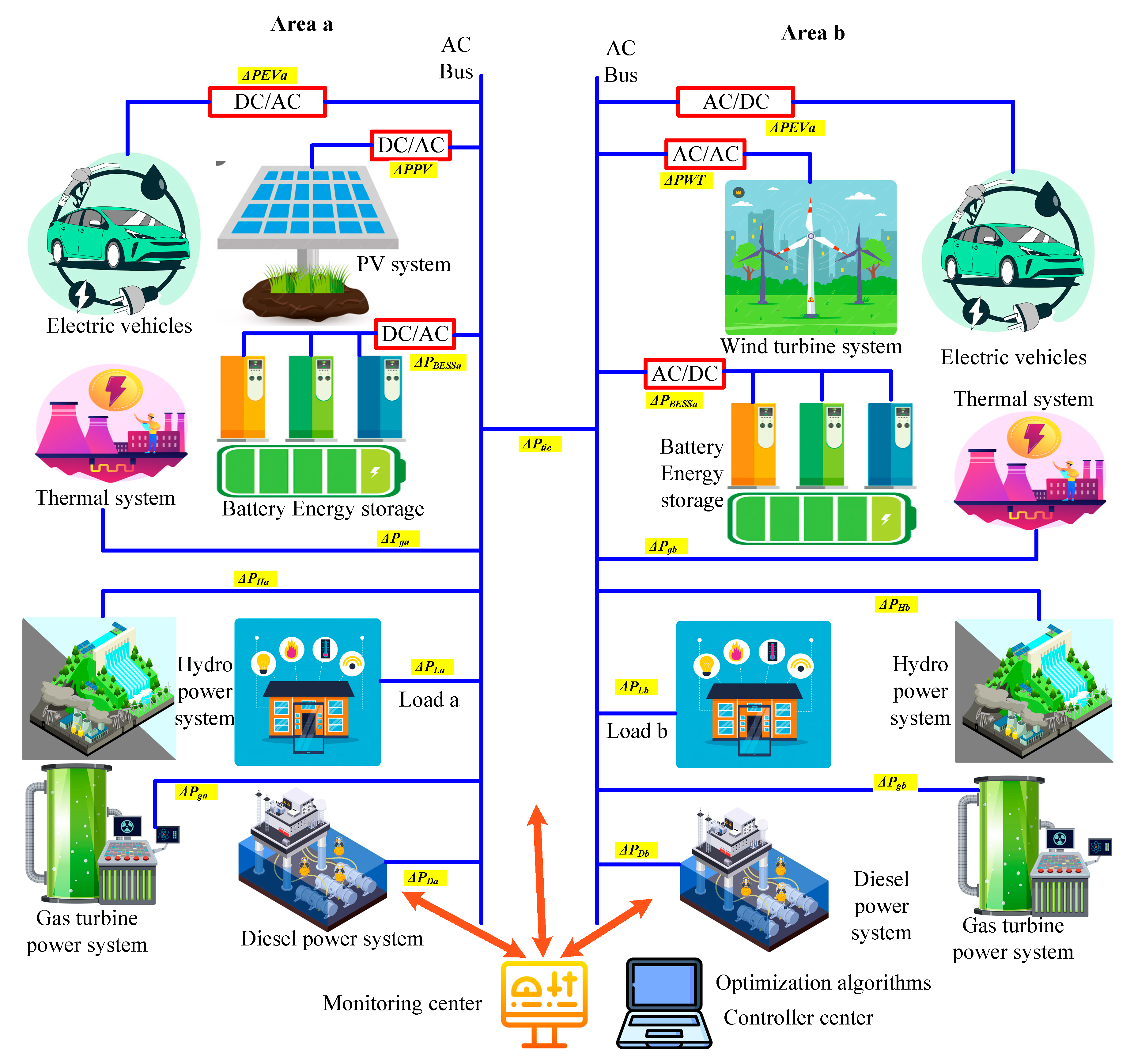
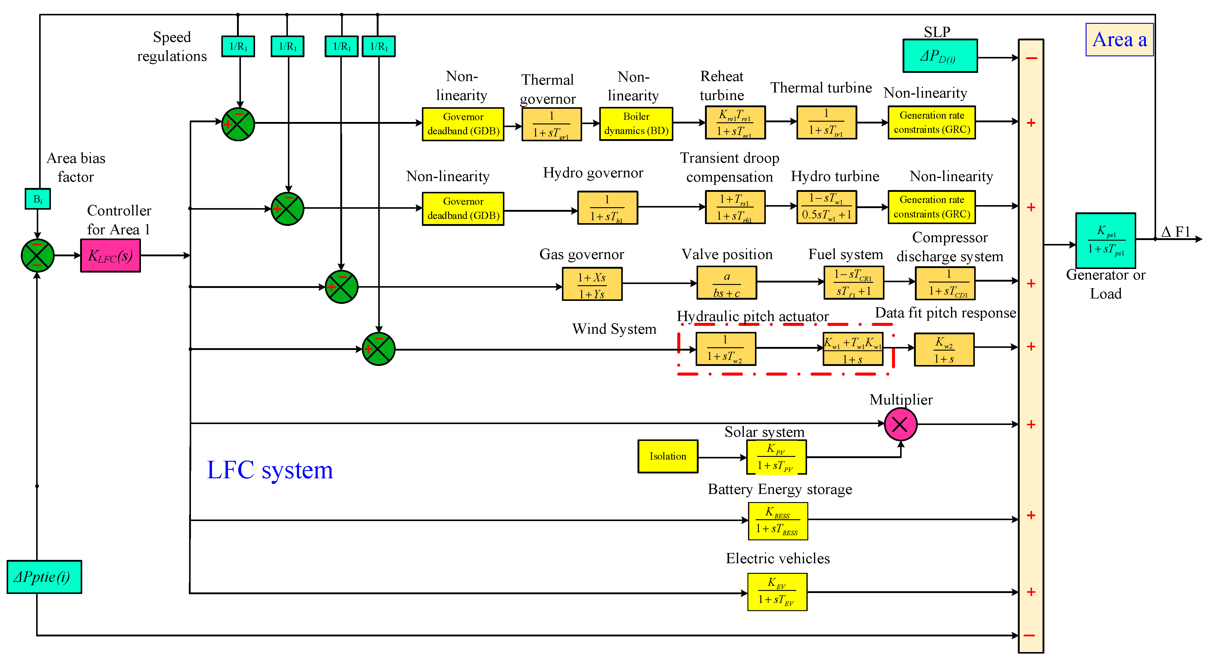
This section presents a schematic representation of the planned AC MG system, which is divided into two parts. It has two models. Figure 1 displays the diagram of the smart hybrid energy system where different renewable and conventional sources, such as hydro, wind, PV, gas turbines, diesel generators, and thermal systems supply electricity through an AC bus to serve loads in two areas (a and b). Converters (AC/DC and DC/AC) enable compatibility between source ESSs and EVs. A monitoring and optimization center coordinates power flow, guaranteeing efficient energy delivery and system constancy. Figure 2 shows the LFC system in a multi-source power system, where various generation units (thermal, hydro, gas, wind, solar, battery storage, and electric vehicles) are coordinated to maintain frequency stability. Each source is modeled with its respective governors, turbines, and nonlinearities, while compensators and constraints regulate their dynamic response. The controller KLFC(s) adjusts the power output based on area control errors, tie-line power deviations, and system bias, ensuring that supply and demand remain balanced across Area-a.
Figure 1.
Integrated hybrid energy system with renewable, conventional, and storage units connected through AC buses and managed by centralized monitoring and optimization.
Figure 2.
Detailed transfer function model of a multi-source LFC system integrating thermal, hydro, gas, wind, solar, battery storage, and electric vehicles to control power balance and frequency stability.
The controller KLFC(s) processes the area control error (ACE), bias factor Bi, and tie-line power deviation ΔPtie(i) to regulate generation. Each power source has its own transfer function:
- Thermal unit: The thermal unit regulates power output using a governor and boiler dynamics, followed by a reheat turbine and a thermal turbine . Abrupt changes are limited by nonlinearities like GRC and governor deadband. This ensures smooth response to load variations but with relatively slow dynamics due to steam and boiler processes.
- Hydro unit: Hydro units use a hydro governor and transient droop compensation to regulate water flow through turbines. The hydro turbine transfer function models water inertia and penstock dynamics. Hydro is fast-acting compared to thermal, but nonlinearities and GRC still affect performance.
- Gas unit: The gas unit employs a gas governor , a valve location controller , and a fuel system . Finally, the compressor discharge system accounts for pressure dynamics. Gas turbines offer quick response, making them suitable for handling sudden load changes in LFC.
- Wind unit: Wind units use a hydraulic pitch actuator to adjust blade angle, followed by a pitch response model , and a wind dynamic transfer . These regulate aerodynamic efficiency and power capture, but their performance depends on wind availability, introducing uncertainty into frequency control.
- Solar unit: The solar unit is exhibited as a simple first-order transfer function with an isolation stage. Its contribution to LFC is limited due to intermittency, but combined with fast power electronics, PV can support grid stability when sunlight is available.
- Battery Energy Storage (BESS): BESS dynamics are modeled as . Batteries provide rapid charge/discharge capability, making them very effective in compensating sudden load disturbances and supporting frequency stabilization.
- Electric Vehicles (EVs): The EV fleet is represented by , acting as a distributed storage system. Through vehicle-to-grid (V2G) technology, EVs can insert or engross power quickly, contributing to short-term frequency control and grid resilience.
- The outputs of all sources are summed, and after system dynamics , they determine the frequency deviation ΔF1 in Area-a.
2.1. Modeling of Plug-in EVs
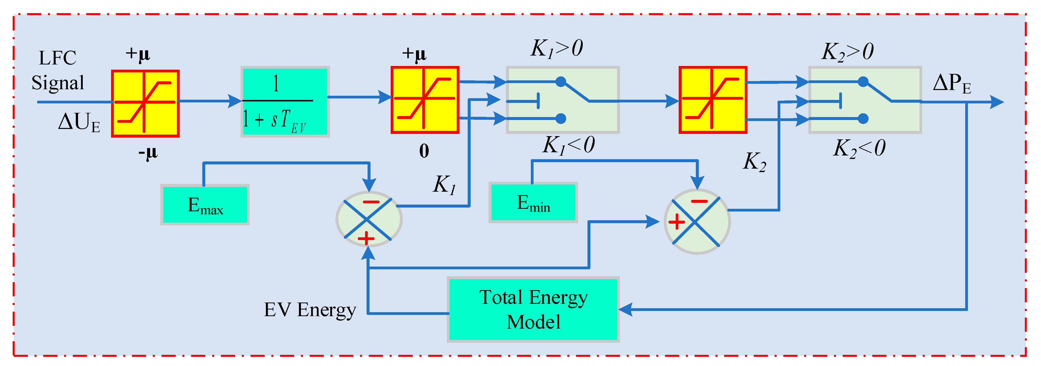
To model the collective behavior of EVs across stations with varying populations, an equivalent EV model with aggregated inverter capacity can be employed. This approach, as proposed in [] for LFC studies, is illustrated in Figure 3. The model incorporates T_e as its time constant and ΔU_E as the LFC command signal. The inverter’s power capacity is well-defined via the range ±μ.
Figure 3.
Model of plug-in electric vehicle.
The framework establishes E_min and E_max as the lower and upper limits of the EV’s controllable energy, respectively, ensuring the EV’s energy (E) remains within these bounds. K1 = E − E_max and K2 = E − E_min are the formulas used to compute the energy variances. A positive number denotes discharging, a negative value shows charging, and a value of zero denotes an idle state. ΔP_E is the symbol for the EV’s charging or discharging power.
Let the LFC command be ΔUE(t). The first saturations (the labels ±μ and 0) indicate limits. Saturation to [ −μ, +μ]:
In the first-order EV actuator (the cyan block 1/(1 + sTEV))
The block (labeled upper +μ, lower 0) acts like a half-saturation (only magnitude for the active direction passes):
Define the direction (charge vs. discharge) from v(t):
Let EEV(t) be the EV’s stored energy and Emin < Emax be the bounds. The two summing nodes compute how close we are to the limits:
A sign-dependent gain K1 (block with the K1 > 0/K1 < 0 switch) penalizes commands that would push energy beyond limits. A simple, effective law is
so that w(t) reduces push toward a violated limit (note the sign flip in the discharge case).
You can also view (6) as the switch labeled K1 > 0/K1 < 0. The nonlinear shaping and outer gain block are another saturation satμ applied to the “shaped command”:
Then a directional outer gain K2 (block with the K2 > 0/K2 < 0 switch) maps this to power command, followed by a final relay/saturation to enforce output limits (rightmost yellow + switch):
Here K2(+) > 0 (charging path) and K2(−) < 0 (discharging path) match the switch “K2 > 0/K2 < 0”, and Pmax is the output power limit (the final yellow block). For the energy dynamics (“Total Energy Model”), the long feedback arrow indicates that the power command updates stored energy. A common model with charge/discharge efficiencies ηc,ηd∈(0, 1] is
The clamp Emin ≤ EEV ≤ Emax is enforced implicitly by Equations (6)–(8): when EEV→Emax (emax→0), the term w(t) attenuates charging commands; when EEV→Emin (i.e., emin→0), it attenuates discharging commands [].
2.2. Integration and Modeling of GRC, GDB, and BD
The physical restriction on how quickly a power-producing component may raise or reduce its output is known as the GRC. These restrictions are brought on by the inherent thermal dynamics of the turbine system, mechanical inertia, and safety considerations. In order to guarantee that the unit performs within reasonable and safe operating margins, typically, GRC constraints cap the turbine’s output increase and decrease rates. Dynamic simulations that disregard GRCs may provide unreasonably quick power changes that do not accurately represent the performance of real power systems.
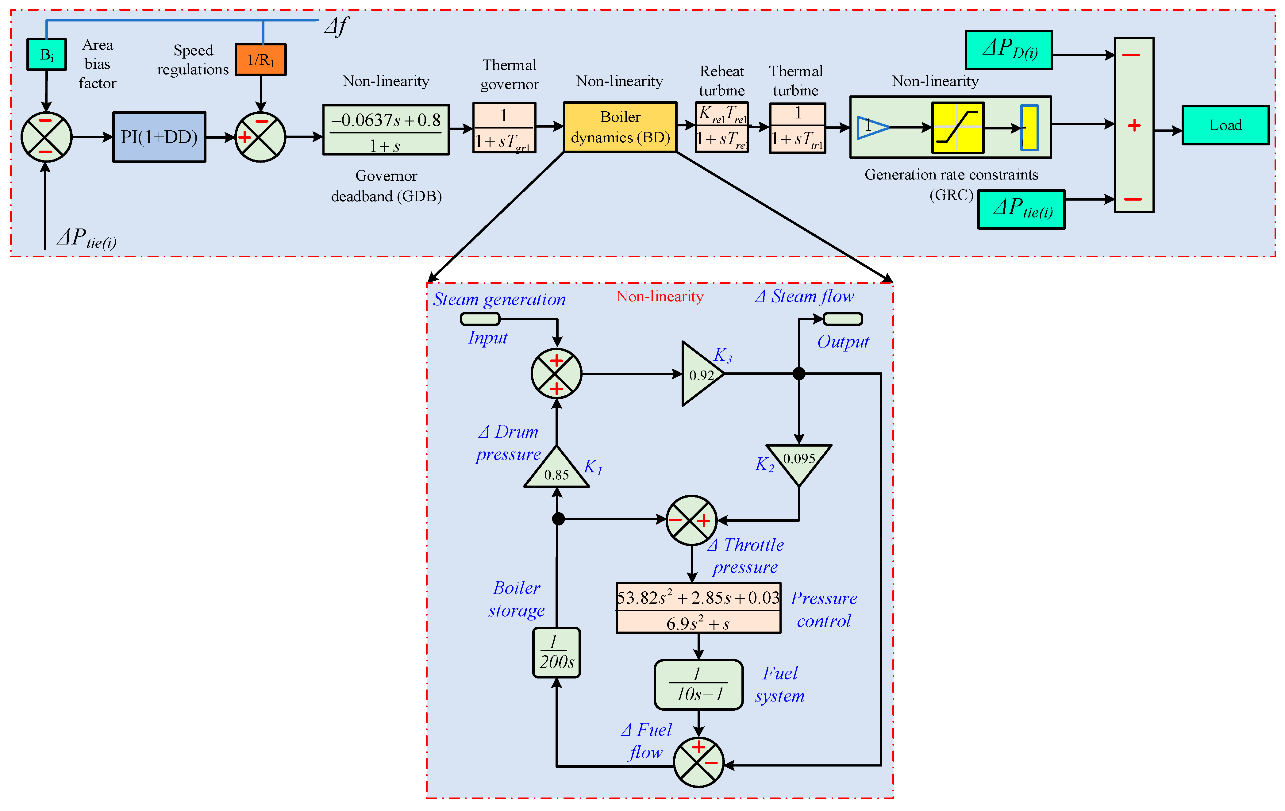
To accommodate this practical constraint, Figure 4 presents a nonlinear representation of the linear non-reheat turbine model that explicitly integrates GRCs limited at (α = ±0.025) per unit per second. The saturation function in this nonlinear framework accurately captures the delayed behavior brought on by thermal lag and physical inertia by imposing rate constraints on the turbine’s power output. This modeling technique avoids spurious performance increases in simulation experiments by ensuring that turbine output variations follow realistic dynamic trajectories, as shown in Refs. [,]. GDB defines the tolerance in speed deviation where the governor does not respond. It indicates how thoughtless the acceleration control device is, and is sometimes given as a percentage of the maximum speed allowed. A nonlinearity of the backlash kind is used to simulate GDB. The GDB is fixed at ±0.02% for hydropower plants and may be computed using for thermal reheat facilities [].
Figure 4.
Nonlinearities in the LFC paradigm (GDB, BD, and GRC).
The BD transfer-function model in Figure 4 incorporates the combustion control system and can be used for gas/oil units with modest ignition accuracy as well as coal-fired plants with strict ignition control. Most steam power plants regulate output via turbine control valves. When deviations in steam pressure or flow are detected, the boiler control system acts promptly to restore stability. Figure 4 presents the equivalent BD transfer-function model []. The LFC system with three important nonlinearities, GBB, BD, and GRC is shown in Figure 4. The system incorporates these nonlinear components to reflect practical limitations on frequency regulation. The signal flow progresses from the thermal governor through the governor deadband, then into the boiler and turbine dynamics. The GRC, which reflects constraints in the generating rate, is applied just prior to the load. Accurately replicating the system’s dynamic reaction under real-world operational situations requires this thorough model.
3. Analysis of Dynamic Control Mechanism Systems
The investigation in this area focuses on strengthening the hybrid power system’s resilience, particularly within the context for robustness augmentation. Several control strategies are covered in this discussion, including fuzzy-PID, fuzzy-PI, fuzzy-P, FO-FPID control strategy, fuzzy inferenced SMC schemes (FISMC), adaptive FLC, adaptive FO-Fuzzy-PID (AFO-FPID), fuzzy-PID, fuzzy-PI, fuzzy-P, and PID controllers. Each of these controllers contributes significantly to the power system’s overall resilience and is evaluated for how well it reduces instability and maximizes system performance.
3.1. PID Controller and Objective Function
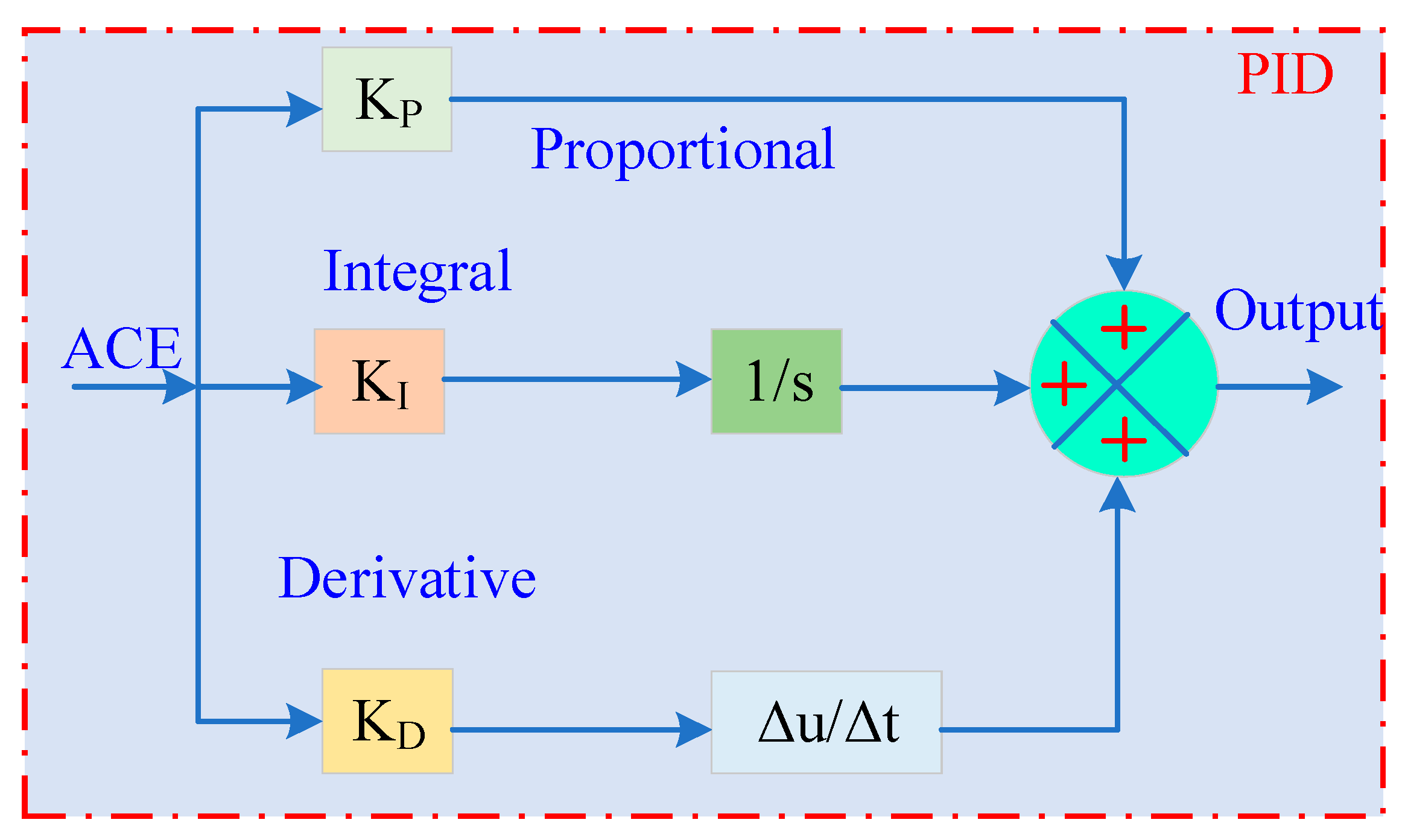
The PID controller remains a practical choice for many control tasks due to its simplicity. Its transfer function in the s-domain is expressed as []
where E(S) represents the tracking error signal, U(S) represents the controller output signal, and kp, ki, and kd represent the gains of the controller. Figure 5 depicts the closed-loop feedback architecture and the controller tuning settings for each location. For a given setpoint Yref, plant output Yplant, and error signal E(t), the controller output U(t) in regions a and b of the closed loop can be written as
where ACEa and ACEb denote the area control errors in Areas a and b. The PID gains are kPa, kIa, kDa and kPb, kIb, kDb. We tune kp, ki, kd to minimize ACE by optimizing three per-unit performance terms: tie-line power deviation ΔPtie, Area-a frequency deviation Δfa, and Area-b frequency deviation Δfb. The baseline objective is the unweighted sum of these metrics (p.u.); four objective formulations are considered in the proposed optimization.
Figure 5.
Basic model of the traditional PID control.
The overall size of the mistake in a system is measured by the Integral Absolute Mistake (IAE), which is the sum of the absolute values of the error across time. Systems where eliminating long-duration mistakes is crucial might benefit from the Integral Time Absolute Error (ITAE), which combines time and absolute error and gives more weight to faults that occur later. Large deviations are often minimized by using the Integral Square Error (ISE), which entails squaring the error values prior to integration and emphasizes larger mistakes more than smaller ones. The Integral Time Square Error (ITSE) is appropriate for systems that need to minimize persistent huge mistakes because it applies a time-weighting component to the squared error, punishing errors that occur later in time more severely—penalties. These metrics are used in control systems to evaluate performance based on different error penalizations.
The limitations of the control parameters that are taken into consideration can be expressed using the following expression:
where n stands for either region a or b. With an initial condition of 0.01 for each gain, the suggested technique chooses the lowest (min) and greatest (max) bounds of the gains in the interval [0, 10], respectively. To validate the effectiveness of the revised controller settings, we evaluate both steady-state and transient responses of the closed loop. Improved steady-state performance is reflected by lower integral indices—ITAE, ISE, ITSE, and IAE—while enhanced dynamic behavior is indicated by shorter settling time and reduced peak overshoot/undershoot, together signifying better overall stability and efficiency.
3.2. Fractional Order (FO-PID) Controllers
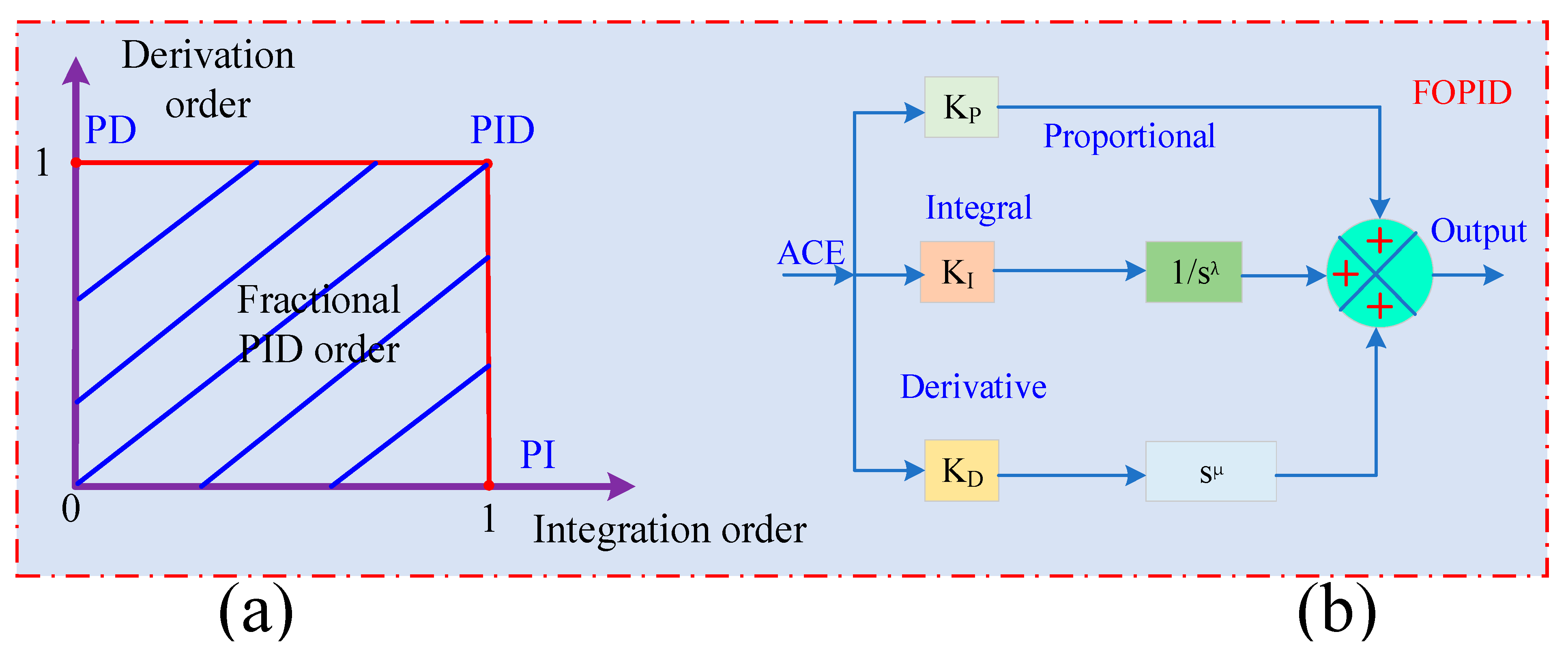
Fractional-order (FO) technique: The dynamic differential equation , serves as the motivation for defining the straightforward differential expression of fractional order, which is used to solve additional complex equations based on nonlinearity. The simplest form of the differential equation based on fractional exponents is . The formula states that order “n” indicates an integer number and α indicates a non-integer value. The FO technique, which is utilized to build a number of basic controllers, originated with Capulos’ fractional calculus. Calculus describes the operator , which is noted as a fractional integra-differential (FID) function []. Once more, this FID is made as
The format for displaying f(t) and αth is as follows:
In the aforementioned statement, m is an integer and α is a real number that falls between m and (m − 1). In Laplace form, Equation (20) may be expressed as
Based on the expression above, ,, and .
Accounting for fractional orders in the integrator and differentiator (λ, µ), the FO-PID controller can be written as
where Kp, Ki and Kd are the proportional, integral and derivative gains, and λ and μ denote the fractional orders of the integral and derivative actions, respectively. In this work, λ and μ are treated as tunable design variables and are restricted to the interval 0 < λ ≤ 1, 0 < μ ≤ 1, which is consistent with standard FO–PID practice and avoids excessively aggressive integral or derivative behavior. Decreasing λ reduces the effective low-frequency gain and integral memory, which mitigates overshoot at the expense of a slower offset removal, whereas increasing λ makes the integral action more dominant. Similarly, the parameter μ controls the strength and bandwidth of the derivative action: larger μ improves damping and accelerates the transient response, while smaller μ yields a more conservative derivative effect with increased robustness to noise.
The controller block structure is depicted in Figure 6a,b.
Figure 6.
(a) Fractional-order PID form, (b) block of the classical FOPID controller.
3.3. Fuzzy-PID, Fuzzy-PI and Fuzzy-P Controllers
This study used a fuzzy-PID controller to examine two test systems. In Figure 7, the controller’s structure is depicted []. The scaling factors in this case are KX i and KY i, the first two input gains. After that, fuzzy controller and PID controller are cascaded, with the three PID gains being KP i, KI i, and KD i. To attain better results, the controller’s gains need to be adjusted. The ACE and its derivative, ∇ACE, are included in the input signal that this fuzzy controller receives. The corresponding ACEs provided by the following serve as the error inputs to the controllers:
Figure 7.
Fuzzy PID controller model.
3.4. FO-Fuzzy PID (FO-FPID) Control Strategy
The performance of both regular PID and fuzzy PID control loops is evaluated using fractional values that represent the derivative and integral as exponent. It goes without saying that this upgrade provides more controllability than their basic controller. To represent the intelligent FO-FPID technique, the FO idea and common fuzzy PID controller characteristics are merged. Figure 8 displays the commonly used block diagram for the FO-FPID controller. The system performance can be improved by this updated fuzzy controller (FO-FPID) by introducing nonlinearity. The control law is similar to FO-PID, but the tuning parameters are adjusted through a fuzzy inference system:
Figure 8.
Fuzzy fractional ordered FLC scheme.
3.5. Fuzzy Inferenced SMC Structures (FISMC)
The FL-SMC combines sliding-mode control with a fuzzy logic controller, merging SMC’s robustness with FLC’s adaptive smoothing. The switching gain KX is pivotal: larger KX improves tracking but amplifies noise and increases chattering. Hence KX should be conservatively (or adaptively) tuned with standard chattering-mitigation (e.g., boundary layer/saturation). The switching gain KX adapts to disturbances (load changes, transients) to enforce the sliding condition s = 0. As the switching gain of the SMC law, KX governs the reaching and sliding dynamics, adjusting the control effort so the trajectory robustly reaches and remains on the sliding surface. As KX rises, the updating pace quickens, and as KX falls, the updated speed is reduced while the chattering is still loud enough. Increasing KX is intended to increase the update to manage control behavior, which is based on the sliding mode transversal approach. Performance benefits from a larger KX when the state is far from the sliding surface, accelerating the reaching phase. Conversely, when the state is close to the surface, a smaller KX (slower update) is preferred to limit chattering and ensure smooth sliding. The insights from this resilient SMC technique are used to create the fuzzy rule-controlled SMC approach [].
The fuzzy–SMC adapts the switching gain KX to the state–surface distance dx so as to reduce tracking error and chattering. As shown in Figure 9a, fuzzy rules infer the effective gap dx between the current state and the sliding surface Sx and adjust KX accordingly—larger when far, smaller when near. The resulting distance profile dx is illustrated in Figure 9b.
Figure 9.
(a) SMC-based FLC loop. (b) Sliding surface re.
3.6. Adaptive Fuzzy Logic Control
A fuzzy logic controller (FLC) handles uncertainty by adapting its rules in real-time from incoming data.
where Ri are fuzzy rules, and λi are the weights associated with each rule.
3.7. ANFIS (Adaptive Neuro-Fuzzy Inference System)
ANFIS is a hybrid system that combines fuzzy logic with neural networks. It adapts fuzzy membership functions by utilizing neural networks’ capacity for learning:
where μi(e(t)) are the membership functions and Ri are the outputs of the fuzzy rules.
3.8. Proposed Hybrid Controller and RBBMO-Based Tuning
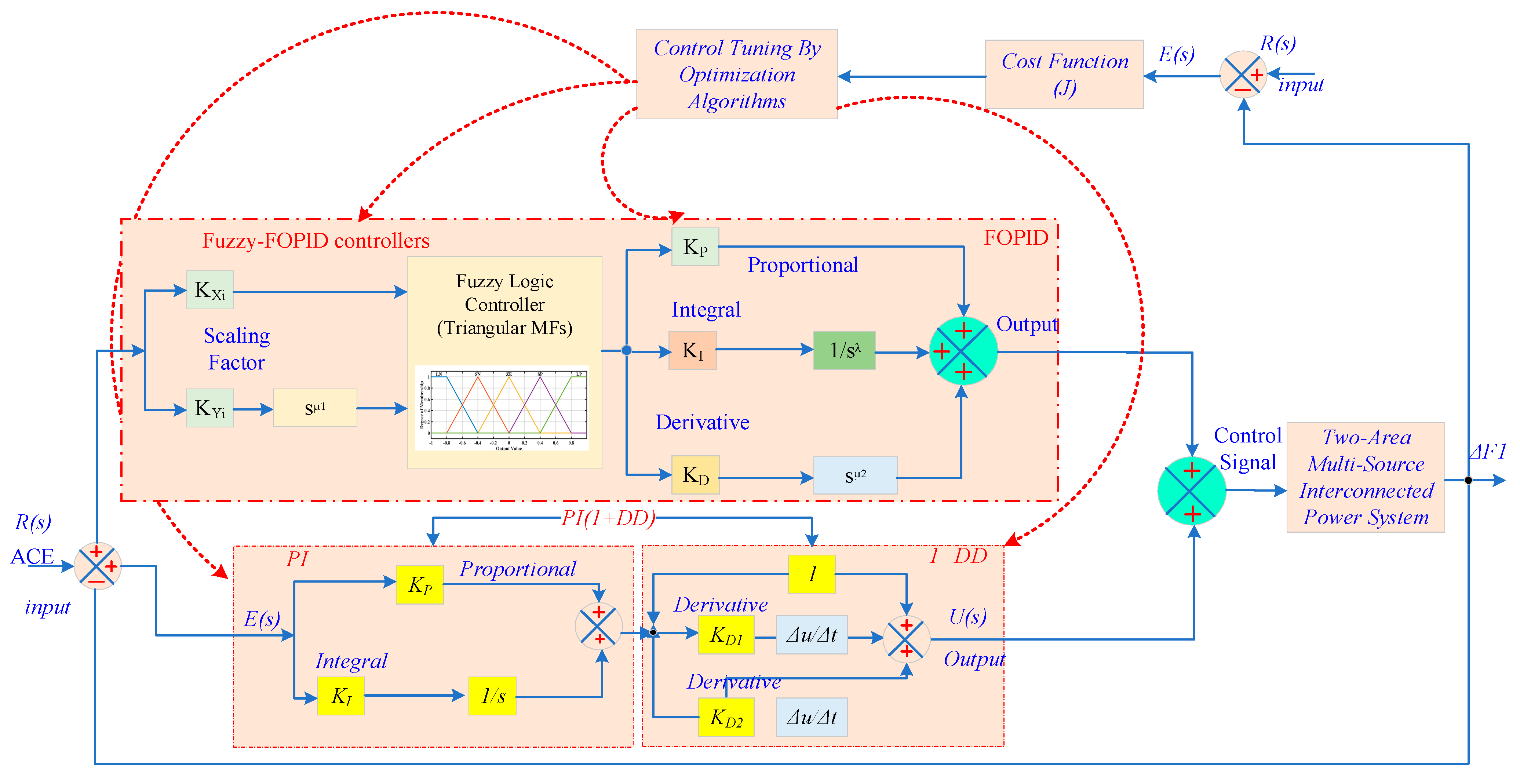
This section presents a hybrid secondary LFC law that combines a fuzzy–fractional PIλDμ (FOPID) branch with an auxiliary PI(1+DD) branch, tuned jointly by the RBBMO as shown in Figure 10. The objective is to secure fast frequency restoration and tie-line regulation under steps and stochastic load changes while respecting actuator limits. The ACE and its derivative, ACE˙, are two normalized input variables that are scaled using gains K1 and K2, respectively, in the FLC configuration. The FLC produces one output signal, which is used as the FOPID controller’s input.
Figure 10.
The configuration of the proposed LFC system.
3.8.1. Signal Definitions and Architecture of LFC
Let the ACE be defined as
Equations (27) and (28) define the regulation error that the secondary controller must drive to zero in each control area. Δfi(t) is the frequency deviation in Area i; Bi (MW/Hz) is the frequency-bias factor that weights frequency error in ACE; and ΔPtie,12(t) is the deviation of actual tie-line interchange from its schedule (positive from Area-a to Area-b). The opposite signs ensure conservation: a positive export by Area-a penalizes ACEa and rewards ACEb. ACE couples frequency restoration and tie-line power regulation in a single error signal; regulating ei→0 enforces both tasks.
A useful linear tie-line model is
where ΔPtie,12(s) is the linearized dynamic relation between frequency differences and tie-line power deviation. T12 > 0 is the synchronizing coefficient, and the integrator 1/s reflects the energy accumulation on the tie-line. Function. It introduces cross-coupling between areas: any mismatch in frequencies causes a drift in inter-area power, which the controller must counteract via ACE.
3.8.2. Fuzzy Input Normalization
The scaling and shaping of raw ACE for a robust fuzzy inference is shown in Equation (30):
where K1,i, K2,i > 0 normalize error and error-rate into [−1,1] so the membership functions are used over their effective domain. Function. It prevents rule saturation when the system sees large transients, and ensures sensitivity around the operating region.
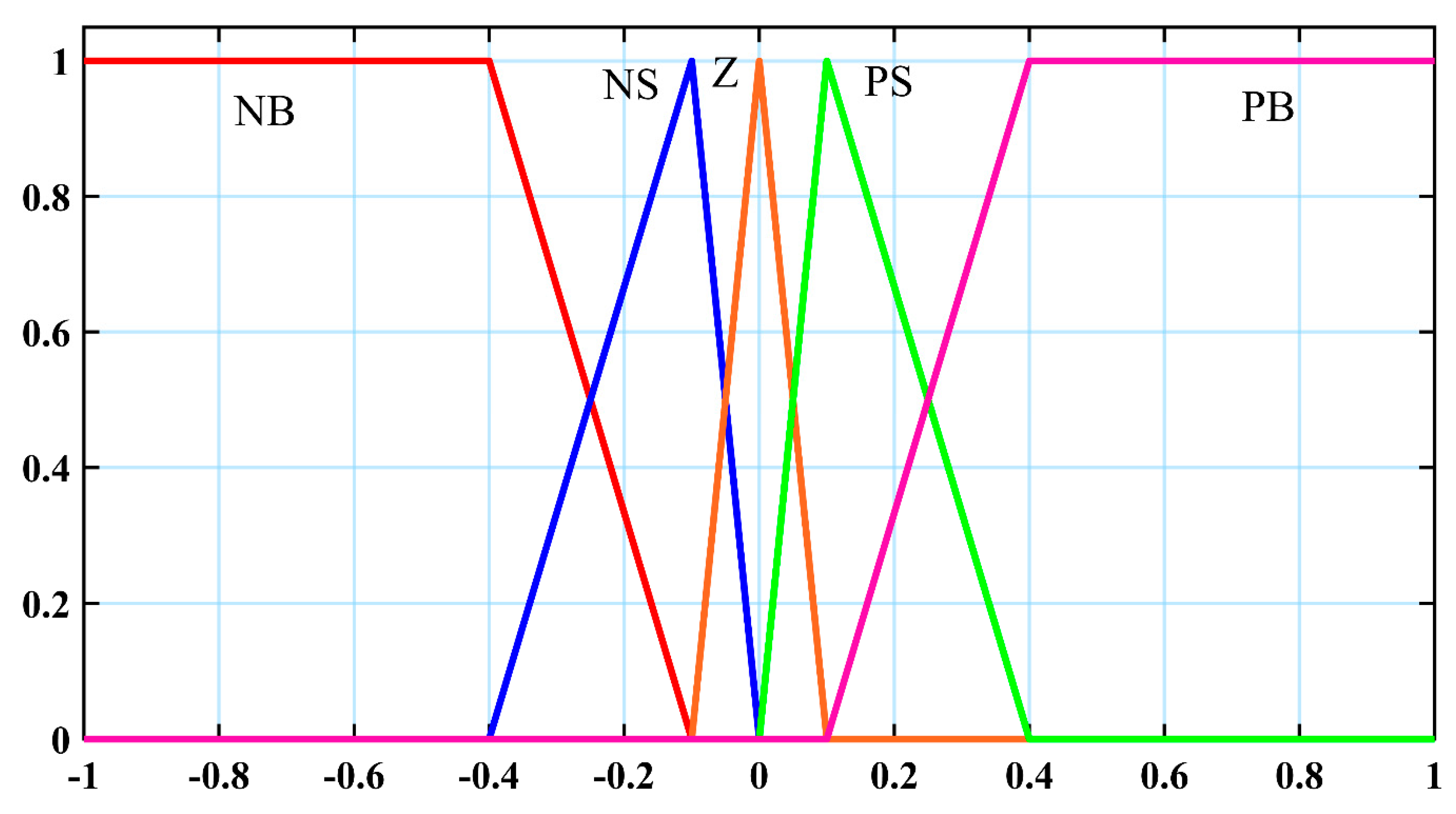
To ensure real-time applicability and optimize computational performance, the FLC fuzzifies using triangular membership functions (MFs). Figure 11 illustrates the classification of inputs and outputs into five linguistic categories: Zero (Z), Positive Small (PS), Positive Big (PB), Negative Big (NB), and Negative Small (NS). The inference system is governed by a rule base comprising 25 fuzzy rules that have been expertly written (Table 2) and are intended to match the dynamic behavior of the target system. Crisp inputs are mapped to fuzzy sets using the Mamdani inference process, and a deterministic control signal is fashioned through defuzzification using the centroid approach.
Figure 11.
FLC membership functions.
Table 2.
FLC rule component.
3.8.3. Parallel Hybrid Control
Each area uses the same structure (run in parallel):
Therefore, each area’s command is the sum of two complementary branches acting on different frequency ranges. Function. The fuzzy–FOPID branch offers bias rejection and damping (low–mid band), while the PI(1+DD) branch provides filtered lead for fast events and Rate of Change of Frequency (ROCOF) suppression (mid–high band). Saturation protects actuators and avoids integral wind-up.
- (1)
- Fuzzy–FOPID branch (Area i)
Fractional controller driven by the fuzzy output yf,i. the Fuzzy–FOPID transfer function:
where Kp,i sets proportional stiffness; KI,is−λi is a fractional integral (order λi) that removes steady-state bias with less wind-up than a pure integrator; Kd,isμi is a fractional derivative (μi) providing phase lead with reduced noise amplification compared with a pure first derivative. Function. Fractional orders tune the nonlocal memory of the controller, trading bias rejection, damping, and noise sensitivity. The time-domain FOPID law with fractional operators can be expressed as
where the Role of Equation (33) is to realize the FOPID in the time domain using the fuzzy surrogate yf,i.
Function. The integral term Iλi{⋅}, accumulates long-horizon error to remove bias; the derivative term Dμi{⋅} anticipates error changes to improve transient damping; using yf,i instead of raw ACE reduces the impact of measurement noise and outliers. Therefore, the fractional operators (Caputo form) as Equation (34):
where the Role of Equation (34), and formal definitions of the memory operators used by the FOPID. Function. Their power-law kernels assign a weight to past information; λ < 1 gives slower, more robust accumulation than an ideal integrator, and μ < 1 yields “soft” differentiation that improves the phase without amplifying high-frequency noise.
- (2)
- PI(1+DD) filtered-lead branch (Area i)
The PI action multiplied by a filtered first- and double-derivative lead as Equation (35):
where KP2,i, KI2,i provide classical PI regulation on ACE; TD,i sets a first-order lead to improve phase margin and reduce overshoot; TDD,i adds a small second-order lead to tame ROCOF spikes; and Tf,i > 0 low-pass filters the lead to keep noise under control. Function. Shapes mid–high frequency response for sharp load changes while preserving robustness through Tf,i. The PI(1+DD) time-domain action as Equation (36):
where zi(t) is ACE passed through the (1+DD) filter. The Role of Equation (34) makes the PI act on a predictive error ei + zi rather than raw ACE. Function. The pre-emphasis zi(t) anticipates fast ACE excursions without the noise explosion of an unfiltered derivative; the PI part then enforces zero steady-state ACE.
- (3)
- (1+DD) Infinite Impulse Response (IIR) recursion
The role is to stabilize IIR realization of the filtered lead after bilinear transform with sampling Ts.
After Tustin,
The Function of Equations (37)–(41) is to produce a clean predictive correction vi[k] used by the PI update below; coefficients are explicit functions of TD,i, TDD,i, Tf,i, Ts.
- (4)
- Discrete PI with anti-windup
The role of Equations (42) and (43) is for the real-time update of the auxiliary branch to command with integral protection. Function. The integrator guarantees zero steady-state ACE; the proportional difference term speeds up transients; saturation on Ii prevents wind-up when actuators hit limits.
- (5)
- Discrete FOPID output (per area)
- (6)
- Final command and limits (per area)
The role is to parallel the combination with actuator protection. Function. Ensures feasibility of the control signal and stabilizes the integrators in both branches during saturation episodes.
3.8.4. Red-Billed Blue Magpie Optimizer (RBBMO)
The RBBMO is an optimization that simulates the cognitive abilities of the RBBM swarming. It was launched in 2024 [,]. The RBBMO has proven to be quite effective in a variety of applications, including the LFC technique, automobile trajectory preparation and tracking monitoring, and fuel cell simulation. The RBBMs’ pursuit effectiveness, which involves target detection, attack, and food preservation, inspires the RBBMO. The RBBM’s primary habitats involve forests in China, India, and the Southeast Asian region. The RBBM eats tiny creatures, fruits, and bugs. When RBBMs move in teams, they find meals more quickly and work together to increase output. RBBMs additionally gather nutrients from the ground and trees and save it for future consumption [].
RBBMs’ instinctual actions are employed to improve numerous key components of the RBBMO method. These birds of prey are recognized for their communal abilities, vocal interactions, and coordinated foraging behavior. They frequently forage in tiny, efficient communities, relying on activities like distributing food, warning calls, and leadership obeying. In RBBMO, where animals communicate information about food sources (solutions) and adjust their motions as needed, these techniques promoted a balance between exploration and exploitation. The approach incorporates physiologically derived ideas such as the transfer of information, which is comparable to how magpie species use linguistic and glances for communication in resource-rich areas; flexible motion structures, which depend on sudden alterations to orientation and nonlinear flight paths; and retention and acquisition capacities, which are expressed in the RBBMO via adaptive memory elements and fitness-based likelihood distributions. The RBMO’s conceptual framework combines the exploration and exploitation stages.
- (1)
- Initialization
The procedure that follows describes how the RBMO creates an indeterminate beginning solution Xj,k:
where r1 is an arbitrary number ranging from 0 to 1, Popu is the population’s size, Dim is the problem dimensions, and LLk and HLk are the lower and upper limits of resolution k.
- (2)
- Seeking Food
To improve search efficacy, RBMs automatically seek small flocks of two to five species or large groups of 10 or more birds. Equations (47) and (48) are used to update the locations of searching agents in both small and large collections.
where n is the present iteration number, Xj(n + 1) is the current location of the search for news agent jth, and r2 and r3 are arbitrary numbers ranging from 0 to 1. Xj indicates the jth bird, Xrc indicates the searching agent randomized in the present cycle, L indicates the number of large sets of RBBMs randomly picked from the overall population, and S indicates the number of small sets of RBBMs chosen at random from the overall population.
- (3)
- Attacking Prey
RBBMs pursue their prey with exceptional skill and collaboration. Equation (49) shows that a small set targets little prey, whereas Equation (50) shows that a large set targets numerous animals.
where XF(n) denotes the meal’s place , and r1 and r2 are the random numbers used to produce a distribution that is normal (typical deviation 1, average 0).
- (4)
- Storing Food
The following is how RBBMs store surplus food for subsequent consumption:
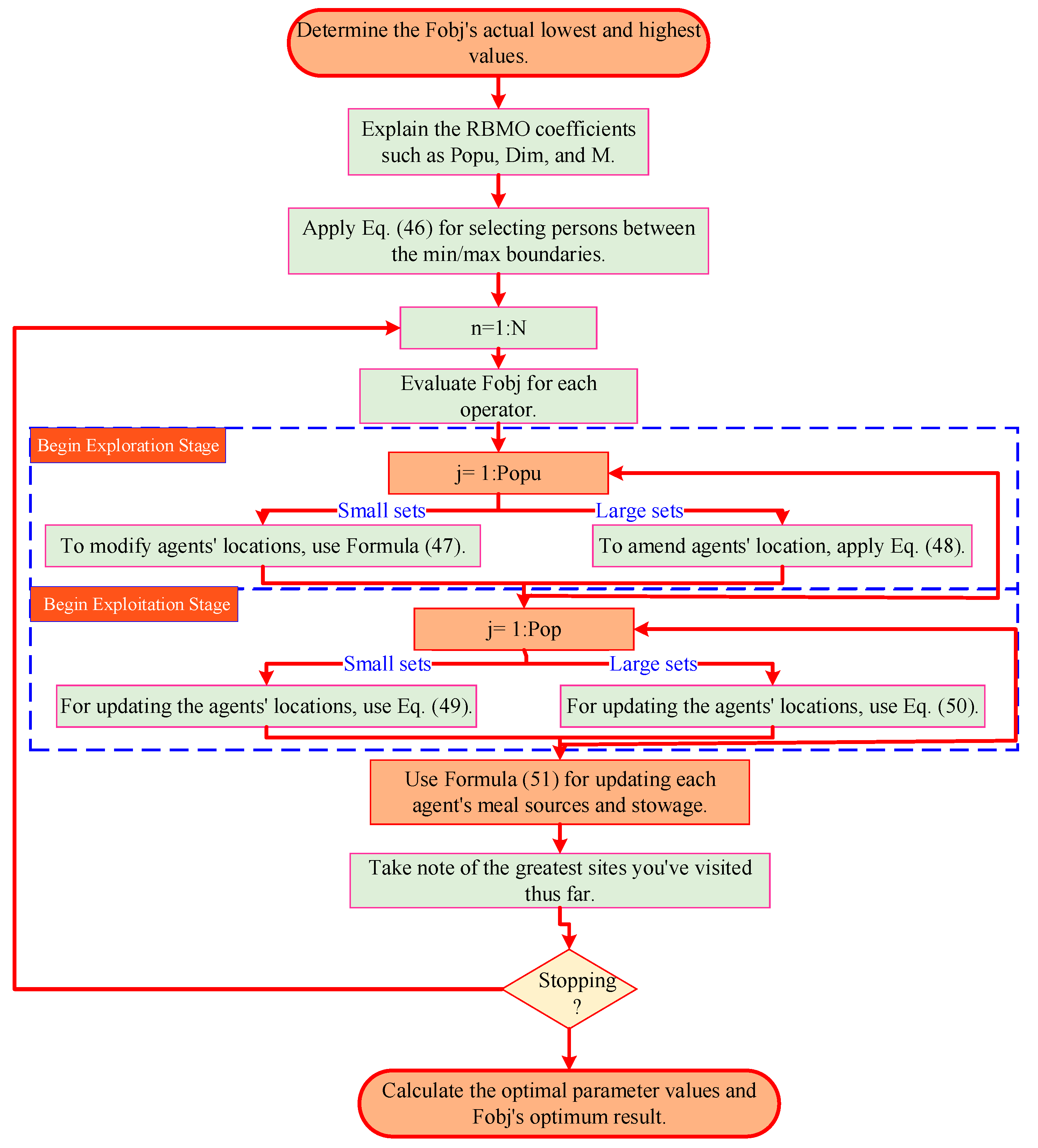
The parameters represent the settings of the target function before and during the updating of the ith RBBM region. The RBBMO has a superb research approach and an excellent execution. All of the RBBMO’s material, including an examination of its distinctive features with those exhibited by other meta-heuristic optimization techniques and its pseudocode, may be found in []. Figure 12 depicts the RBBMO’s workflow.
Figure 12.
The RBBMO workflow.
3.8.5. RBBMO for Tuning the Proposed Hybrid (Fuzzy-FOPID) + PI(1+DD) Controllers
The parameter vector (θ) stacks all tunable numbers for both areas: fuzzy input scalers (K1,i, K2,i), FOPID gains and fractional orders (KP,i, KI,i, KD,i, λi, μi), and the PI(1+DD) branch gains and time constants (KP2,i, KI2,i, TD,i, TDD,i, Tf,i). Area-’s 12 parameters and Area-2′s 12 parameters are optimized together so the two controllers cooperate across the tie-line rather than fighting each other.
where K1,i, K2,i: scalers that normalize ACE and its derivative before the fuzzy block (keep fuzzy membership functions in their effective range). KP,i, KI,i, KD,i, λi, μi: fuzzy–FOPID gains and fractional orders. s−λi (fractional integral) removes bias with less wind-up than a pure integrator; sμi (fractional derivative) gives smooth phase lead without amplifying noise. KP2,i, KI2,i: PI gains of the auxiliary branch. TD,i, TDD,i, Tf,i: the filtered lead shape (1+DD); TD (lead), TDD (small extra lead for ROCOF), Tf > 0 (low-pass to limit noise). Each control area has its own controller but the tie-line term couples both via the objective, so the optimizer searches over the joint 24-dimensional vector to find a pair that works well together.
The objective J(θ) integrates, over the evaluation horizon, time-weighted absolute frequency errors in both areas, time-weighted tie-line power error, time-weighted ACE in each area, and quadratic control effort. The time factor (t·|·|) makes late errors costly (ITAE), so the optimizer prefers fast settling and small tails; the u2 terms keep control signals smooth and realistic.
where the horizon Tf: time window is used to judge performance (e.g., 100–200 s). Longer windows penalize long “tails”. ITAE-style time weights t|t∣⋅∣: multiplying by t penalizes late errors more than early ones, so the optimizer prefers fast settling with small tails. Terms and their roles ωf,1t∣Δf1∣, ωf,2t∣Δf2∣: keep each area’s frequency near nominal and settle quickly. Raising ωf,i shortens settling time and reduces nadir/overshoot in Area i. ωPt∣ΔPtie,12∣: enforces accurate tie-line interchange (track the scheduled power exchange and eliminate drift caused by frequency mismatch). ωe,1t∣e1∣, ωe,2t∣e2∣: directly penalize ACE (combined frequency + tie-line regulation per area). These help the optimizer balance the two components of ACE if Bi are not perfectly tuned. ωu,1u12, ωu,2u22: penalize aggressive control effort and chatter. Averaging over scenarios: in practice it may evaluate J for several load patterns (step, ramp, stochastic; applied to Area-1 or Area-2) and average the results so the tuned controller is robust, not over-fit to one disturbance.
During simulation (constraints), each area’s command must respect actuator magnitude limits (|ui(t)| ≤ u_max,i) and, if enforced, rate limits (|dui/dt| ≤ ẋu_max,i). Parameter feasibility is also enforced (0 < λ ≤ 1, 0 ≤ μ ≤ 1, Tf > 0, TD ≥ 0, TDD ≥0). These constraints prevent unstable or non-implementable solutions and avoid integrator wind-up. (Effect of weights) Raising ω_f,i speeds frequency recovery in Area i; raising ω_p tightens tie-line regulation; raising ω_e,i pushes ACE (the composite metric) to zero faster; raising ω_u,i reduces control activity and chatter. Normalizing signals (e.g., Δf by 0.1 Hz, ΔP_tie by a MW scale, u in p.u.) makes these weights easier to choose. Why does this objective fit LFC? It captures both secondary-control goals—restoring frequency and regulating interchange—while explicitly rewarding quick recovery (ITAE) and penalizing aggressive actuation. Because the tie-line term couples the areas, minimizing J delivers a pair of controllers that behave well individually and jointly. What does RBBMO do? RBBMO treats θ as a 24-D decision vector, simulates the two-area system for several disturbances, computes J(θ), and iteratively updates a population via exploration (random “flights”) and exploitation (move toward the current best). Elitism preserves the best candidate. The returned θ* is the parameter set that minimizes J under the constraints.
The RBBMO yields faster convergence to optimal controller settings, stronger disturbance rejection, and lower frequency overshoot and settling time than classical tuning approaches. Its key benefits for LFC tuning are the following:
- A coordinated search technique involves a gradual shift from individual to collective activity, resulting in a successful balance between both discovery and extraction.
- Dynamical flexibility: The algorithm can react quickly to changes in the search environment thanks to capture-rate-driven strategy adjustments.
- Strong effectiveness: The RBBMO is ideally suited for power-system optimization due to its steady convergence and good solution accuracy across a variety of benchmarks.
From a computational standpoint, the RBBMO-based tuning operates in a 24-dimensional decision space, but this optimization is performed entirely offline and therefore does not add any burden to the real-time LFC implementation. Each RBBMO iteration evaluates the same closed-loop cost function as the benchmark metaheuristics, so the per-iteration complexity is of the same order as BBOA and related population-based methods, while in our case study RBBMO reaches a satisfactory solution in fewer iterations and thus with fewer total evaluations. Once the optimal parameters are identified, the on-line execution of the proposed hybrid controller reduces to standard arithmetic operations, a compact fuzzy-rule evaluation and low-order fractional-operator realizations, yielding a per-sample load that is comparable to conventional FO–PID and fuzzy-SMC schemes and significantly lower than ANFIS-based designs. As a result, the controller can be realistically implemented on typical industrial DSP, PLC or microcontroller platforms with practical LFC sampling periods.
3.9. Comparative Analysis Framework
In this section, all candidate controllers are assessed under a unified comparative framework to ensure a fair and transparent evaluation. The analysis is structured along four main dimensions. First, transient behavior is quantified using standard time-domain metrics, including frequency overshoot, nadir, settling time and tie-line power deviation for both areas under nominal operating conditions. Second, robustness to disturbances is examined by subjecting the two-area system to large step load changes, renewable power fluctuations, contract violations in Area-2 and partial EV State of Charge (SoC) constraints, and then monitoring the corresponding degradation (or improvement) in dynamic performance. Third, sensitivity to parameter variations is investigated by perturbing key plant and controller parameters (e.g., governor and turbine time constants, droop coefficients and fractional orders) within realistic ranges and observing the impact on the closed-loop response. Finally, computational cost is characterized by the optimization cost values, convergence speed of the RBBMO and benchmark optimizers, and the nominal complexity of the resulting controller structures. All results presented in Section 3 are interpreted with respect to this four-dimensional comparison framework.
4. Results, Discussion and Analyses
A complete series of simulation experiments was performed on the two-area test system represented in Figure 1 to determine the best combination of multiple optimizers and controller architectures. These works cover a wide variety of scenarios intended to fully assess system performance in various settings. Simulations were conducted utilizing the novel RBBMO-FO-Fuzzy-PID+PI(1+DD) suggested in this study compared to numerous controllers and state-of-the-art (SOTA) methods tuning for a two-area interconnected electrical power system with substantial wind–solar penetration. Technical parameters in the power plant model and EV, as listed in Appendix A (Table A1 and Table A2) were applied to all controllers, and a comparison was made.
To provide a broad and meaningful basis for comparison, a diverse set of benchmark controllers is considered. Classical PID and FO–PID schemes are included as widely adopted baselines in LFC studies. ANFIS-PID and fuzzy-SMC represent advanced intelligent and hybrid nonlinear designs that are frequently reported to improve robustness and disturbance rejection in power-system applications. Together with the recent metaheuristic optimizers used for tuning, this benchmark set spans conventional, fractional-order and intelligent control paradigms, allowing the added value of the proposed hybrid controller to be assessed in a comprehensive manner.
4.1. Case One: Renewable Energy and Load Uncertainties
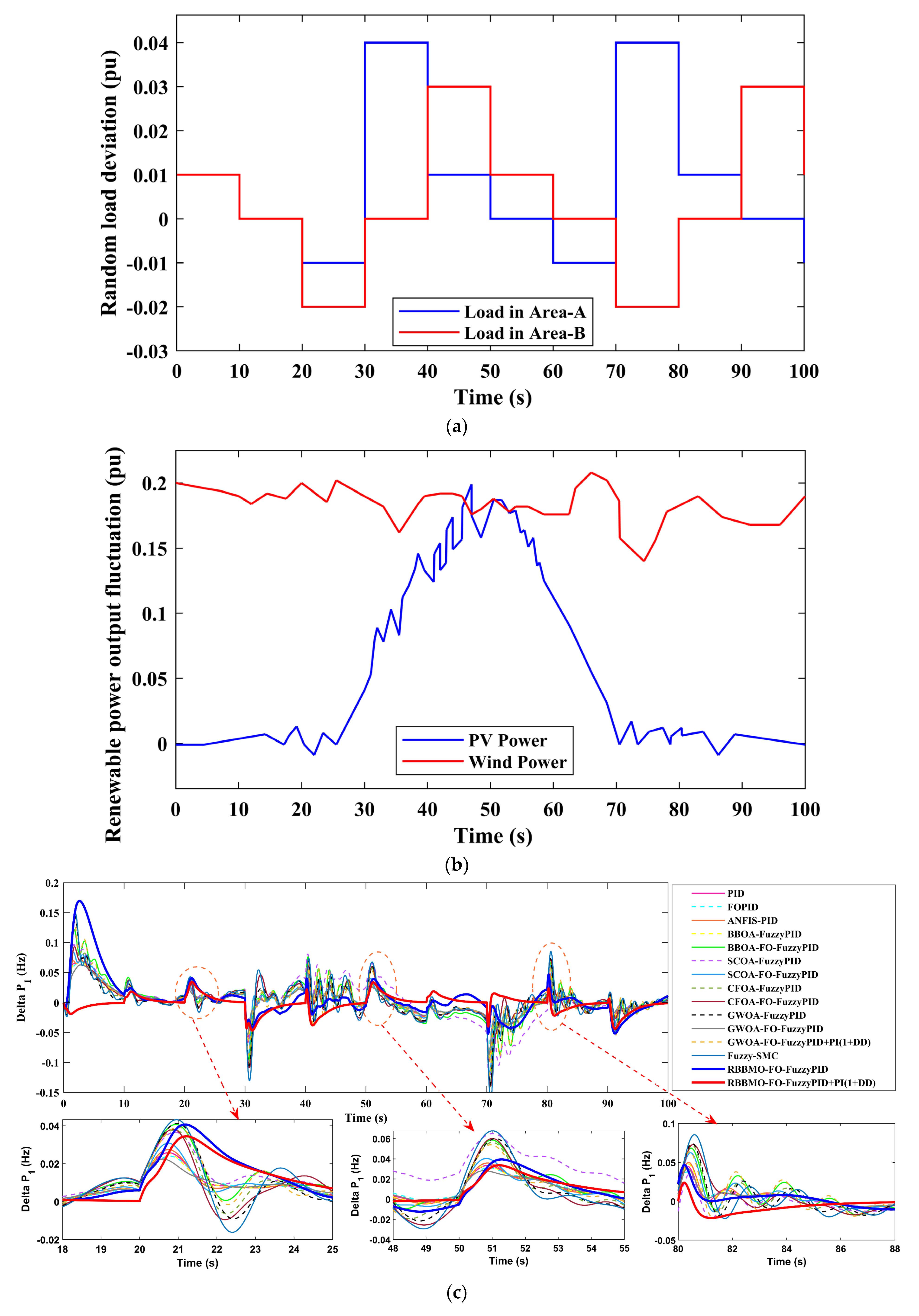
In this scenario the two areas experience asynchronous step-like load changes while the renewable portfolio exhibits a mix of slow ramps (PV) and higher-frequency fluctuations (wind) as shown in Figure 13a,b. The misalignment between these disturbances creates sustained deviations in net generation–demand balance, which appear as bursts in the area control error, brief excursions of tie-line power away from its schedule, and spikes in the Rate of Change of Frequency. PV ramps tend to impose longer, low-frequency drifts in frequency, whereas wind variability injects shorter, higher-frequency oscillations; stepped loads add sharp edges that excite inter-area modes. Without adequate buffering and robust secondary control, the system would show larger overshoot and nadir, longer settling, and periods of increased actuator stress. Coordinated LFC, augmented by fast-responding storage and bidirectional EV support—can counter these effects by absorbing ramps, smoothing flicker, and supplying (or sinking) shortfall/surplus power, thereby keeping frequency within its tolerance band and maintaining scheduled tie-line interchange.

Figure 13.
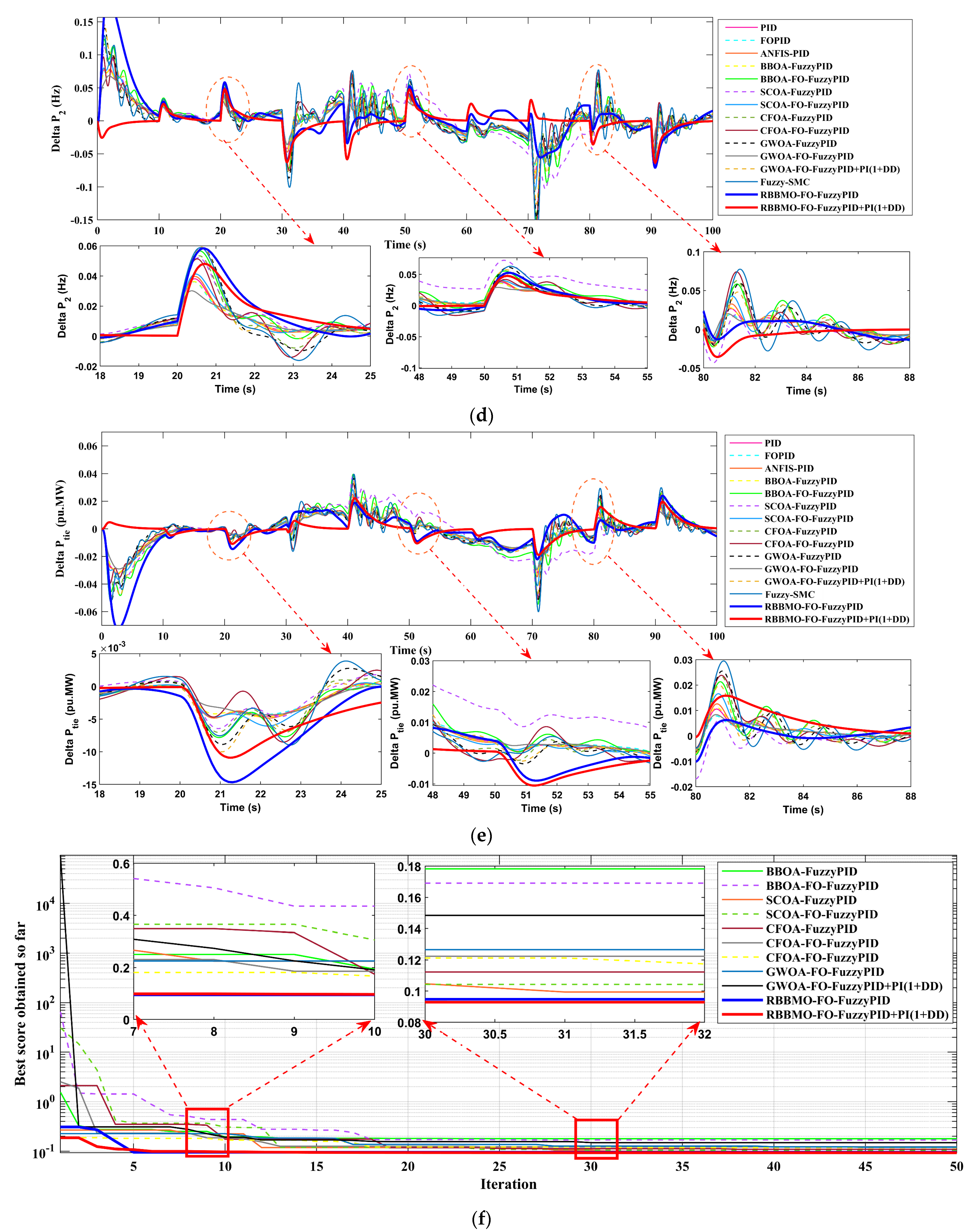
Performance of two-area LFC under renewable and load uncertainties: (a) random load deviations in the two areas; (b) renewable power fluctuations; (c) Area-a frequency deviation (Δf_1); (d) Area-b frequency deviation (Δf_2); (e) tie-line power deviation (ΔPtie) and (f) optimizer convergence for all tuning algorithms.
Figure 13c–f demonstrate the frequency variations in regions A, and B, following a rapid shift in load. The findings demonstrate that the proposed hybrid controller approach lowers the peak value of frequency deviation in every location. The performance of the LFC in removing the load disturbance may be enhanced by employing the proposed controller, as shown in Figure 13c–f; also, the settling time of the frequency response is much reduced.
With each algorithm tuned at its best cost in Figure 13c at Area-a, the proposed hybrid controller exhibits the smallest excursions and the quickest recovery: overshoot 0.06 Hz, undershoot −0.07 Hz, and settling 3–4 s after the 50–55 s event and 4–5 s after the 80–88 s event. The single-branch RBBMO-FO-FuzzyPID overshoots to 0.17 Hz with a nadir −0.12 Hz, settling in 6–7 s and 8–10 s for the same windows. Among strong baselines, GWOA-FO-FuzzyPID+PI(1+DD), CFOA-FO-FuzzyPID, and BBOA-FO-FuzzyPID form a middle tier (overshoot about 0.08–0.11 Hz, nadir −0.09…−0.11 Hz, settling 6–9 s then 8–12 s). Fuzzy-SMC, ANFIS-PID, FOPID, and PID show larger peaks and longer ringing (overshoot roughly 0.10–0.18 Hz, nadir −0.11…−0.14 Hz, settling 8–15 s). Steady-state error for all controllers is essentially zero.
The same ranking repeats in Area-b in Figure 13d. The proposed hybrid controller limits the overshoot to 0.04 Hz with a nadir −0.08 Hz and settles within 3–5 s (50–55 s window) and 4–6 s (80–88 s window). RBBMO-FO-FuzzyPID overshoots to ≈0.15 Hz, nadir ≈ −0.13 Hz, and settles in ≈6–8 s then 8–11 s. The better meta-heuristic baselines (e.g., GWOA-FO-FuzzyPID+PI(1+DD), CFOA-FO-FuzzyPID, and BBOA-FO-FuzzyPID) sit between the two (overshoot 0.07–0.10 Hz, nadir −0.10…−0.12 Hz, settling 6–10 s then 8–12 s). Classical PID/FOPID/ANFIS-PID again trail with longer settling (9–16 s). The steady-state error is 0 for all.
With each algorithm tuned at its best cost in Figure 13e, the proposed hybrid controller yields the tightest tie-line response. In the early event (18–24 s) its undershoots are about −0.010…−0.011 pu·MW, compared with −0.014…−0.015 for RBBMO-FO-FuzzyPID and −0.012…−0.014 for the stronger non-RBBMO baselines. Around the 80–88 s cluster, the overshoot (crest) is +0.017…0.020 pu·MW for the hybrid, versus +0.025…0.028 for RBBMO-FO-FuzzyPID and +0.022…0.027 for others. Using ∣ΔPtie∣ < 5 × 10⁻³ as the settling criterion, the hybrid settles in 5–6 s, RBBMO-FO-FuzzyPID in 9–11 s, and others in 8–15 s. The steady-state error is 0 for all controllers.
Across Table 3, Table 4 and Table 5, the proposed hybrid controller consistently outperforms competing controllers. It delivers smaller overshoot and shallower undershoot in both areas, reaches the settling band markedly faster, and maintains negligible steady-state error. On the inter-area link, it tightens tie-line regulation with reduced excursion and quicker reconvergence. Under RES variability and load uncertainty, it sustains higher tracking quality and energy yield while preserving DC-bus regulation. Compared with single-branch and classical/meta-heuristic baselines, it also requires less actuator effort (fewer and shorter saturation episodes) and shows more robust behavior across scenarios, indicating superior damping, disturbance rejection, and overall reliability for two-area LFC with RES, ESS, and EV participation.
Table 3.
Area-a frequency (Δf1).
Table 4.
Area-b frequency (Δf2).
Table 5.
Tie-line (ΔP_tie).
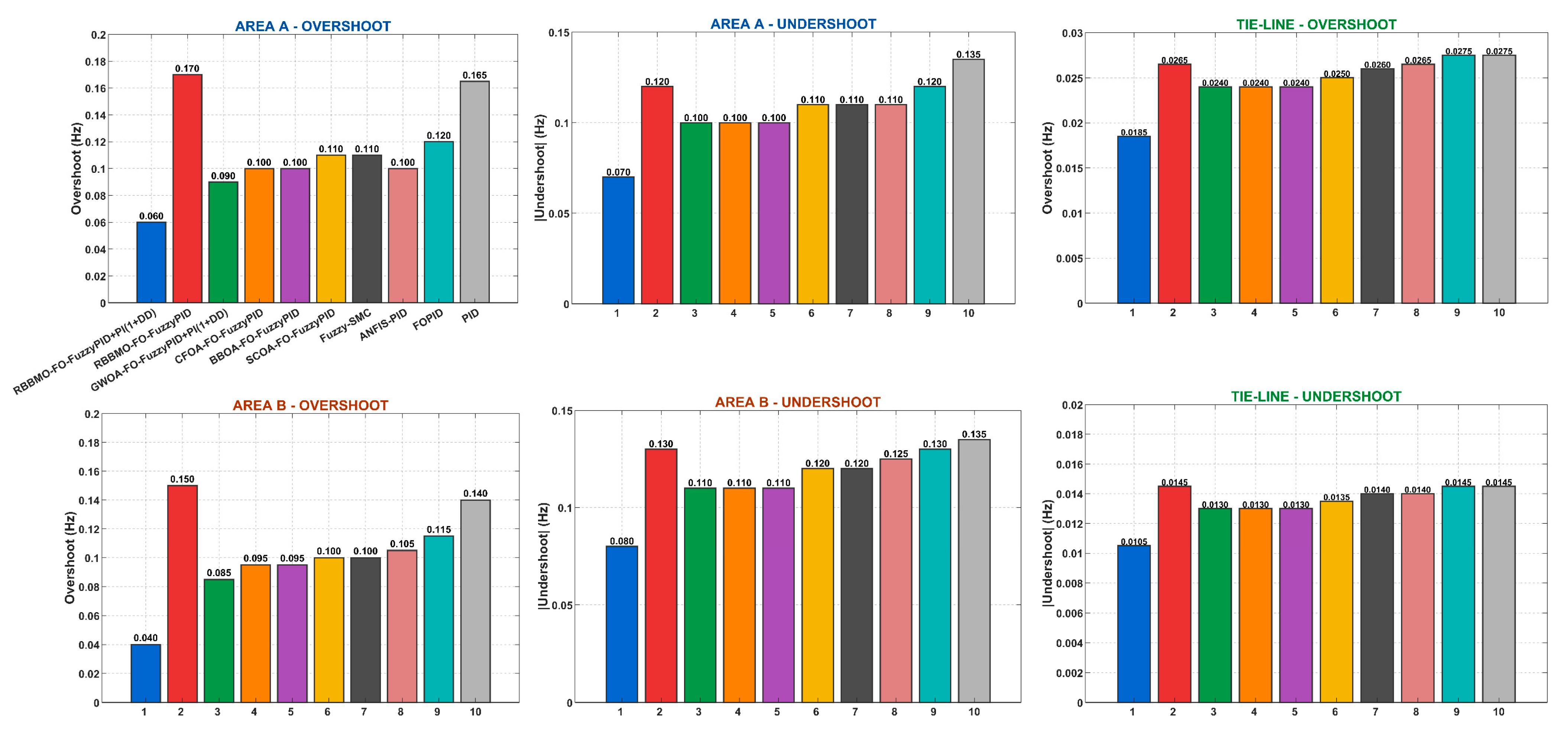
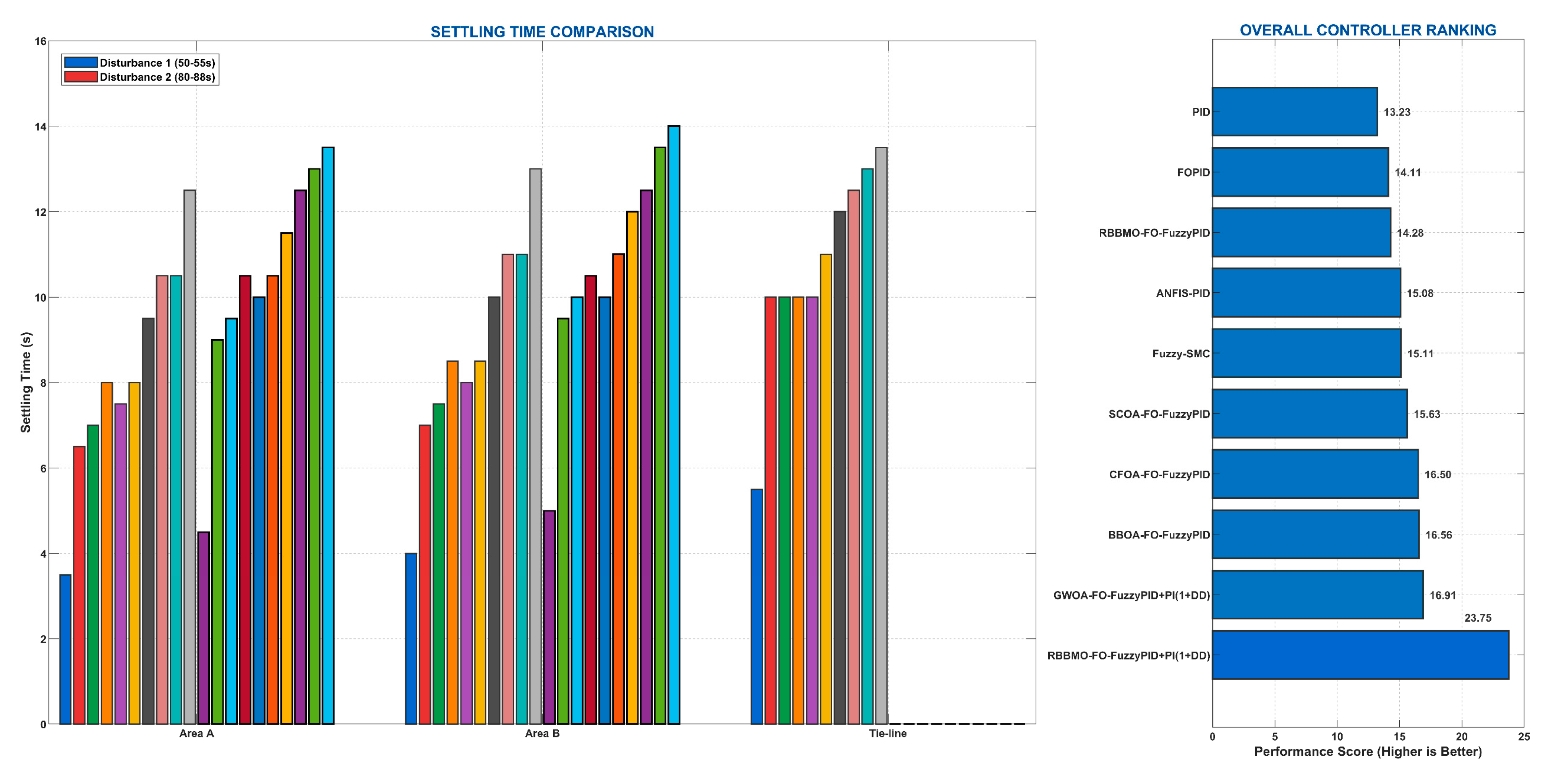
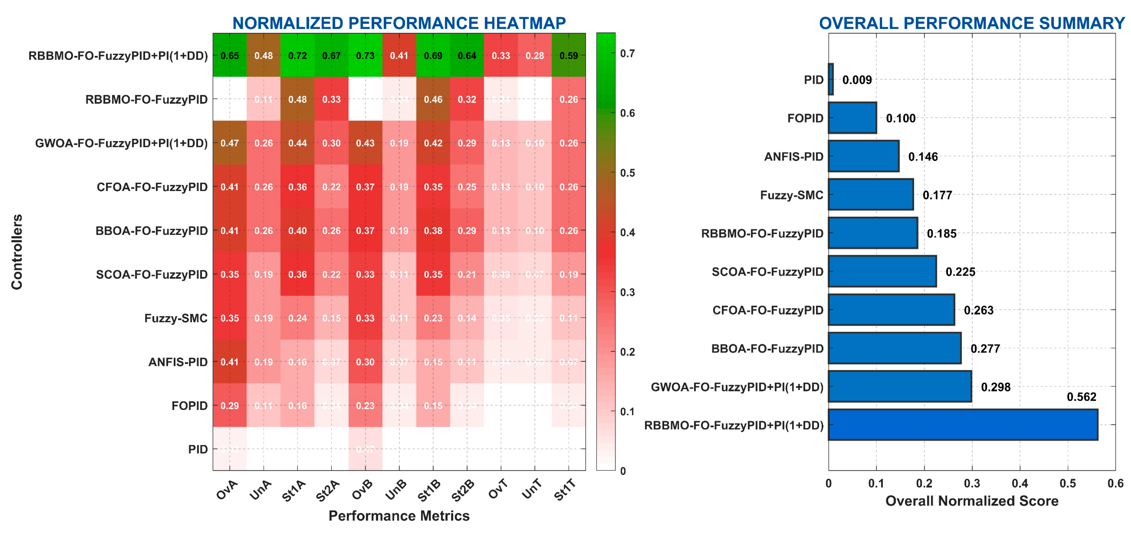
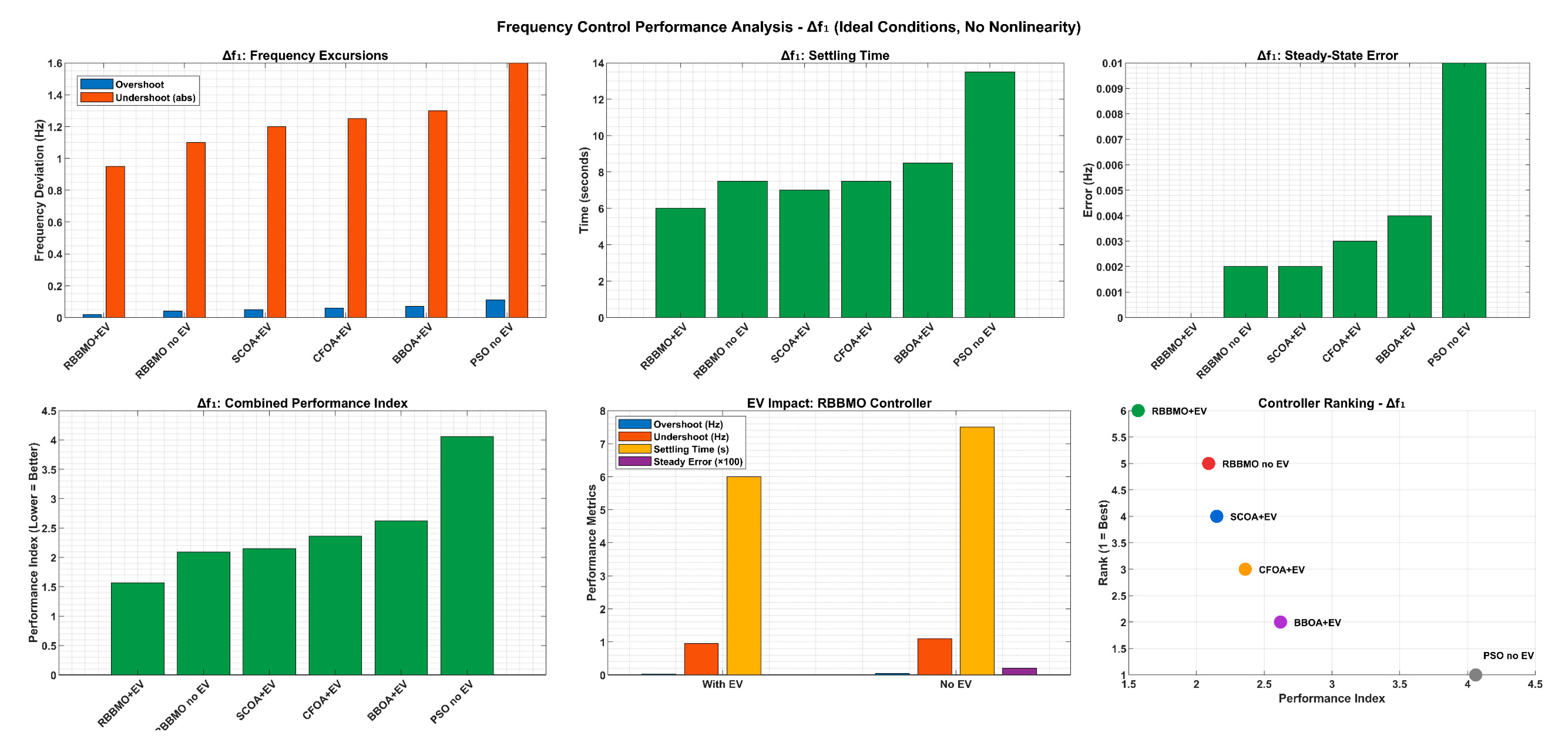
Figure 14 shows how much each controller allows frequency/power to overshoot (positive deviation) and undershoot (negative deviation) from desired values. Lower bars indicate better performance. Figure 15, on the left side, shows how quickly each controller brings the system back to stability after disturbances and the right side provides an overall performance ranking based on combined metrics. Figure 16 shows the visualized multiple performance dimensions simultaneously. Controllers that cover more area perform better across all measured criteria.
Figure 14.
Comparative analysis of controller performance in overshoot and undershoot mitigation for Area-1, Area-2, and tie-line power.
Figure 15.
Settling time performance during two disturbance periods (50–55s and 80–88s) and overall controller ranking.
Figure 16.
Normalized performance radar chart for top six controllers across key metrics.
4.2. Case Two: Bilateral Condition (Ideal Linear Plant vs. 3% GRC)
This scenario probes two operating regimes of the two-area LFC with RES, ESS, and EV participation. In the ideal (no-nonlinearity) regime, governors and actuators are linear and unconstrained, so frequency and tie-line responses reflect the intrinsic damping and coordination provided by the controllers; this serves as the baseline for best-case dynamic quality. In the 3% GRC regime, turbine–governor ramps are limited (slew-rate bounded), which delays mechanical power corrections and tends to enlarge the first excursions, deepen the nadir, and lengthen settling—especially during clustered disturbances and RES ramps. Under both regimes, the proposed hybrid controller maintains the most compact envelopes and the fastest reconvergence by (i) shaping the ACE through fuzzy–fractional action, (ii) using the auxiliary PI(1+DD) branch to add damping without steady-state penalty, and (iii) leveraging ESS/EV support to compensate the GRC-induced lag. Compared with all baselines, it preserves tighter tie-line regulation and smaller control stress in the ideal case, and it degrades gracefully under 3% GRC, sustaining superior overshoot/undershoot performance and shorter settling while keeping steady-state error negligible.
- (1)
- Case: Ideal (no constraints), with vs. without EV participation
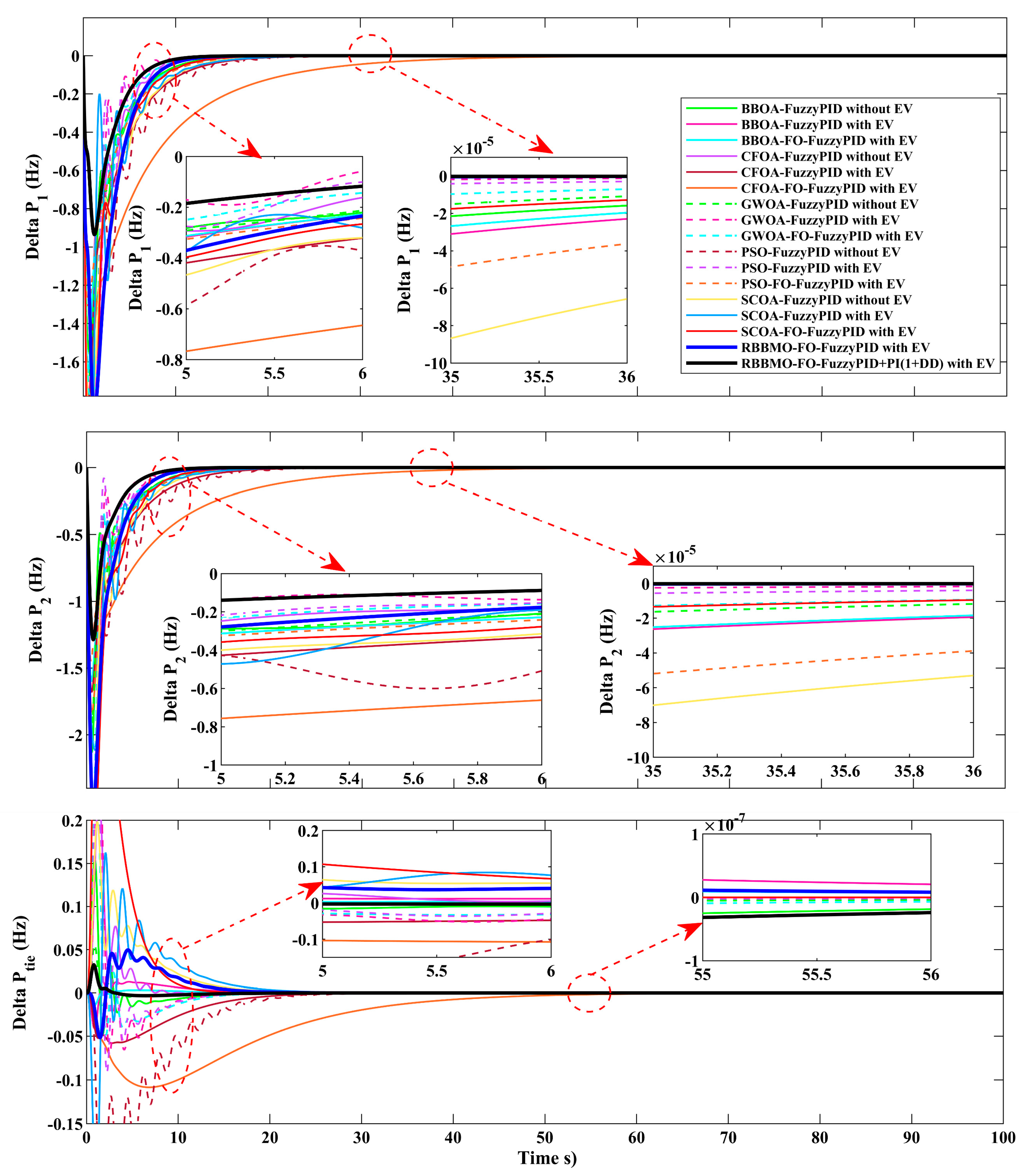
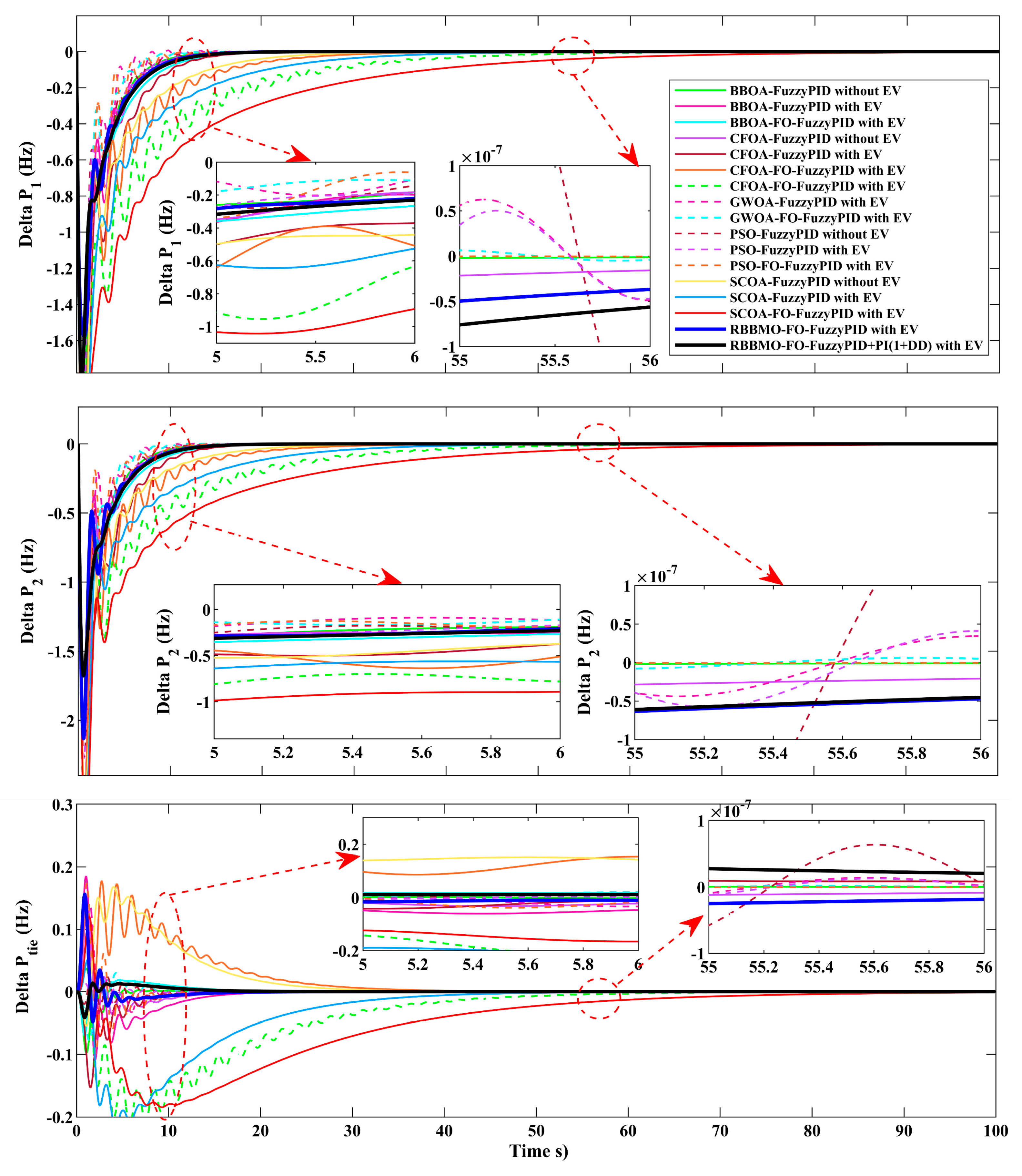
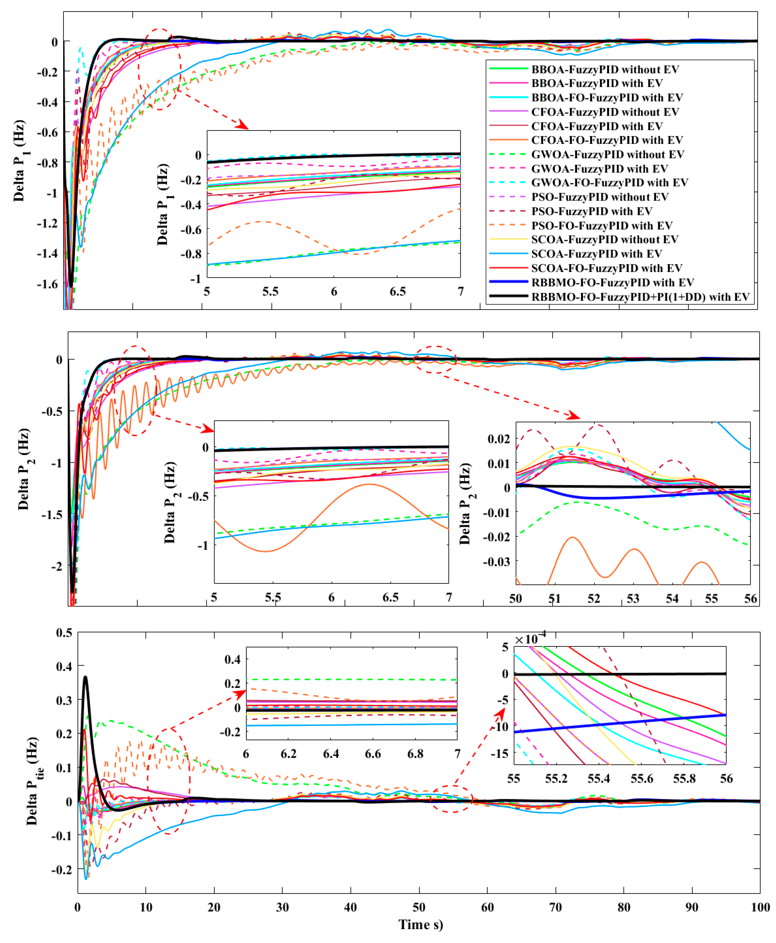
Figure 17 compares the two-area LFC responses when all plant nonlinearities/limits are disabled (no GRC, no dead bands), highlighting the effect of aggregated EVs providing fast V2G/G2V support. Across all controllers, adding EVs consistently compresses the transient envelope in both areas—Δf1 and Δf2 dip less at the start, recover more quickly, and exhibit visibly higher damping (smaller oscillations) as shown in Figure 17 The insets around 5–6 s show that EV-enabled variants track back toward nominal with a steeper slope and reduced residual deviation; the late-time insets (35–36 s) indicate negligible drift for EV cases, whereas non-EV cases settle more slowly. On the inter-area link, in Figure 17, ΔP_tie with EVs shows a much tighter peak-to-peak excursion and faster reconvergence to zero exchange (see the 5–6 s and 55–56 s zooms), confirming improved tie-line regulation. Among all methods, the proposed hybrid controller with EV delivers the most compact response and fastest decay, followed by its non-EV counterpart and then the other meta-heuristic/classical baselines. In short, under ideal linear conditions, EV participation acts as a fast-balancing resource that reduces overshoot and undershoot, shortens settling, and leaves essentially zero steady-state error, amplifying the advantage of the proposed hybrid controller over the alternatives.
Figure 17.
Time responses in the ideal, unconstrained case comparing controllers with EV and without EV: Area-1 frequency deviation Δf1, Area-2 frequency deviation Δf2, and tie-line power deviation ΔPtie.
Under ideal linear dynamics (no dead bands/GRC), adding aggregated EVs (V2G/G2V) improves the transient across all controllers, BBOA-, SCOA-, CFOA-, GWOA-, PSO-based Fuzzy/FO-FuzzyPIDs, RBBMO-FO-FuzzyPID, and the proposed hybrid controller. With EVs, both areas’ frequencies (Δf1, Δf2) exhibit smaller overshoot and undershoot and shorter settling, and the tie-line deviation reconverges faster with a tighter envelope. Among all methods, the proposed hybrid controller with EV is consistently best; the next tier is RBBMO-FO-FuzzyPID with EV, followed by the EV-enabled versions of GWOA/CFOA/BBOA/SCOA/PSO controllers. For every algorithm, removing EVs enlarges the first excursion, deepens the nadir, and lengthens settling, confirming EVs’ usefulness as a fast-balancing resource even when the plant is perfectly linear.
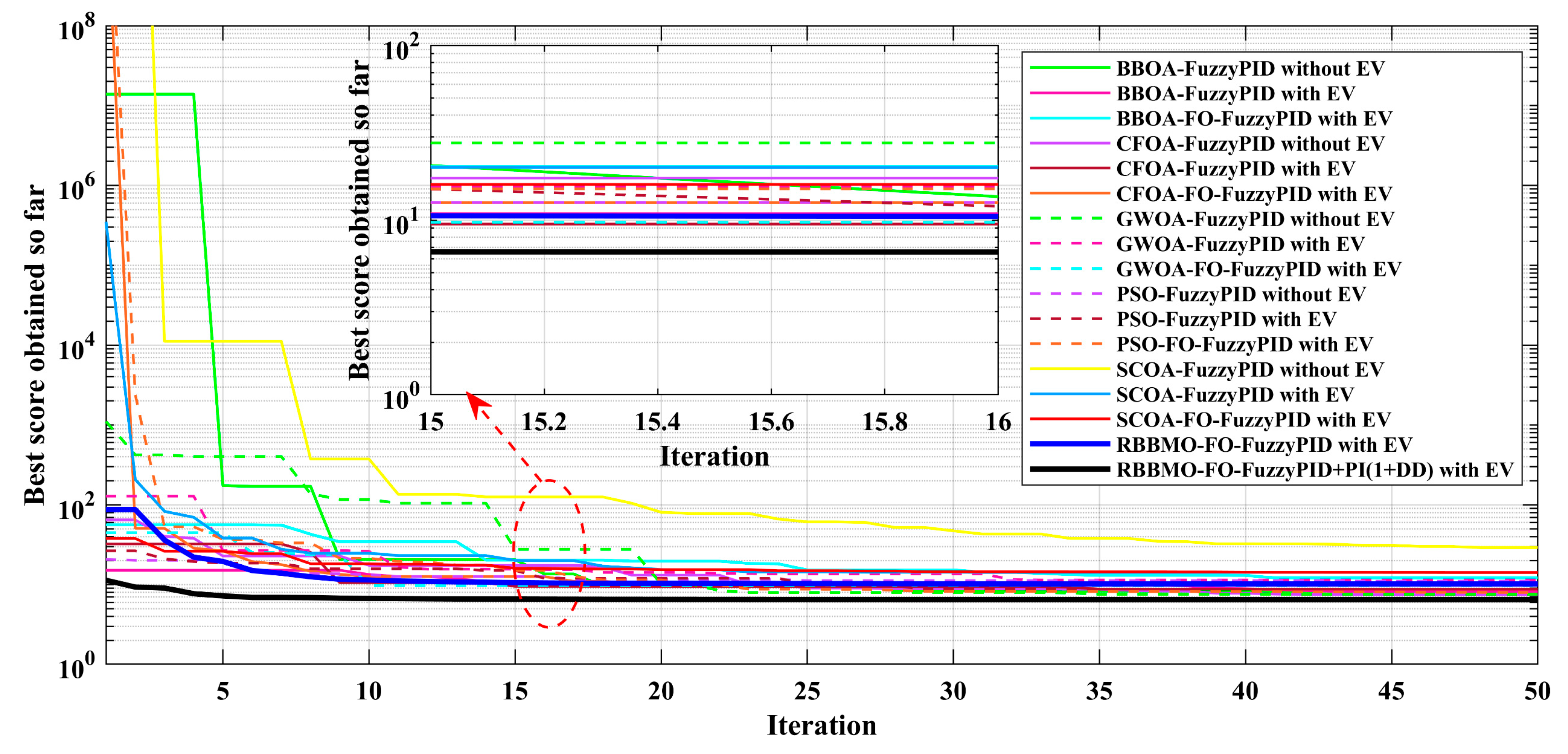
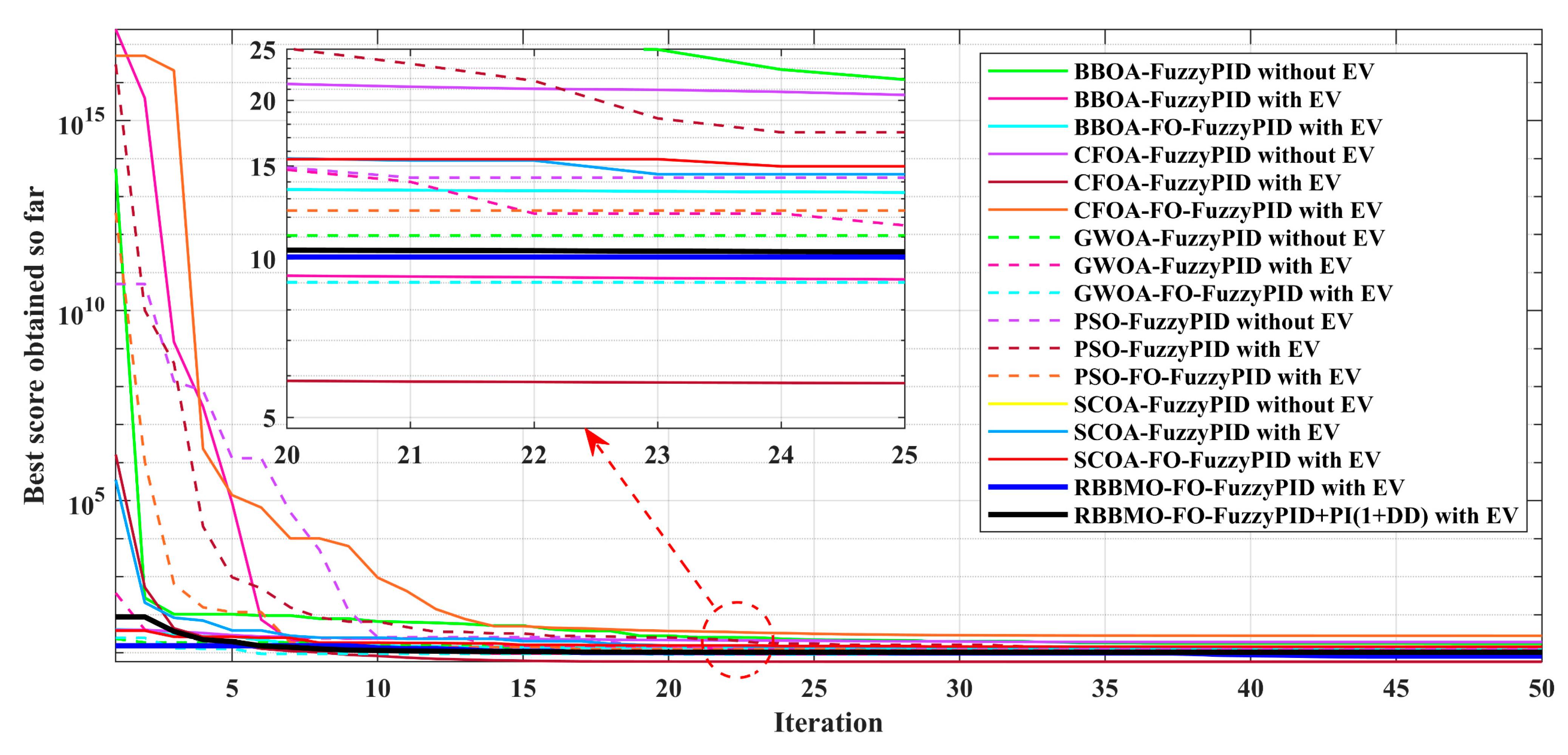
Figure 18 compares the best objective value versus iteration for all tuned controllers under the ideal, unconstrained case, each with and without EV participation. The proposed hybrid controller with EV consistently achieves the lowest final cost and the fastest stabilization—its curve drops steeply in the first few iterations and flattens early, indicating rapid, reliable tuning. The RBBMO-FO-FuzzyPID with EV is the next best, followed by EV-enabled versions of the SCOA-, PSO-, CFOA-, BBOA-, and GWOA-based Fuzzy/FO-FuzzyPID designs, which converge to slightly higher plateaus. For every algorithm, the with-EV variant outperforms its without-EV counterpart, reflecting the additional controllability and better-conditioned objective when fast EV support is available. Some baselines (e.g., SCOA-FuzzyPID without EV) show slower, more stepwise decay and settle at higher costs, signaling less effective tuning and weaker closed-loop damping.
Figure 18.
Convergence of the objective function (“best score obtained so far”) for all controllers in the ideal, unconstrained case, comparing with EV and without EV variants.
Table 6 compares Area-1 transient quality across all controllers, reported as overshoot, undershoot (nadir), settling time in seconds for the two disturbance windows (50–55 s and 80–88 s), and steady-state error. It shows that adding EV participation improves every controller (smaller peaks and faster settling), and that the proposed hybrid controller with EV consistently delivers the tightest envelope and shortest settling, followed by its non-EV counterpart and then the EV-enabled versions of the other meta-heuristic fuzzy/FO controllers. All methods achieve negligible steady-state bias in the ideal plant. And Table 7 repeats the analysis for Area-2. The same ordering holds: EV support improves all algorithms; the proposed hybrid controller with EV provides the smallest overshoot/undershoot and the fastest return to the ±0.01 Hz band, while alternative meta-heuristic designs form a middle tier and their non-EV versions lag. Steady-state error remains essentially zero. Table 8 summarizes tie-line regulation quality using maximum positive/negative excursions (overshoot/undershoot), settling time in seconds to the ∣ΔPtie∣ < 5 × 10⁻³ pu·MW band for the 80–88 s event, and steady-state error. EV-enabled controllers reduce peak exchange and reconverge faster; the proposed hybrid controller with EV achieves the tightest regulation, indicating superior inter-area coordination.
Table 6.
Transient metrics for Area-1 frequency deviation (Δf1): overshoot, undershoot (nadir), settling time to the ±0.01 Hz band in the 50–55 s and 80–88 s windows, and steady-state error. Controllers are reported with and without EV participation; the proposed hybrid controller with EV achieves the best overall performance.
Table 7.
Transient metrics for Area-2 frequency deviation (Δf2): overshoot, undershoot (nadir), settling time to the ±0.01 Hz band for the 50–55 s and 80–88 s events, and steady-state error. EV participation systematically enhances damping; the proposed hybrid controller with EV is dominant.
Table 8.
Tie-line deviation metrics: maximum crest and nadir of ΔPtie, settling time to ∣ΔPtie∣ < 5 × 10⁻³ pu·MW in the 80–88 s window, and steady-state error. EV support reduces excursions and accelerates reconvergence; the proposed hybrid controller with EV performs best.
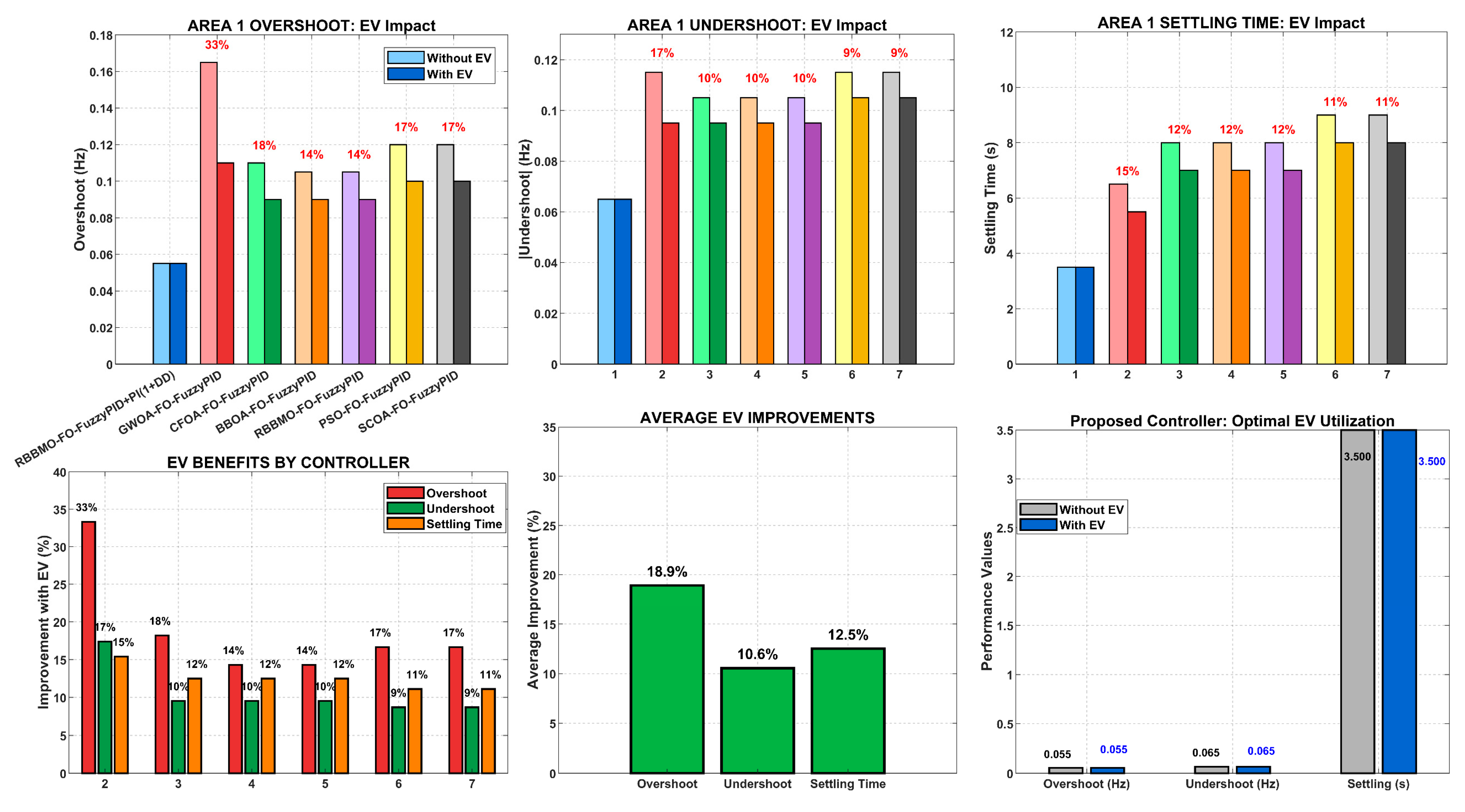
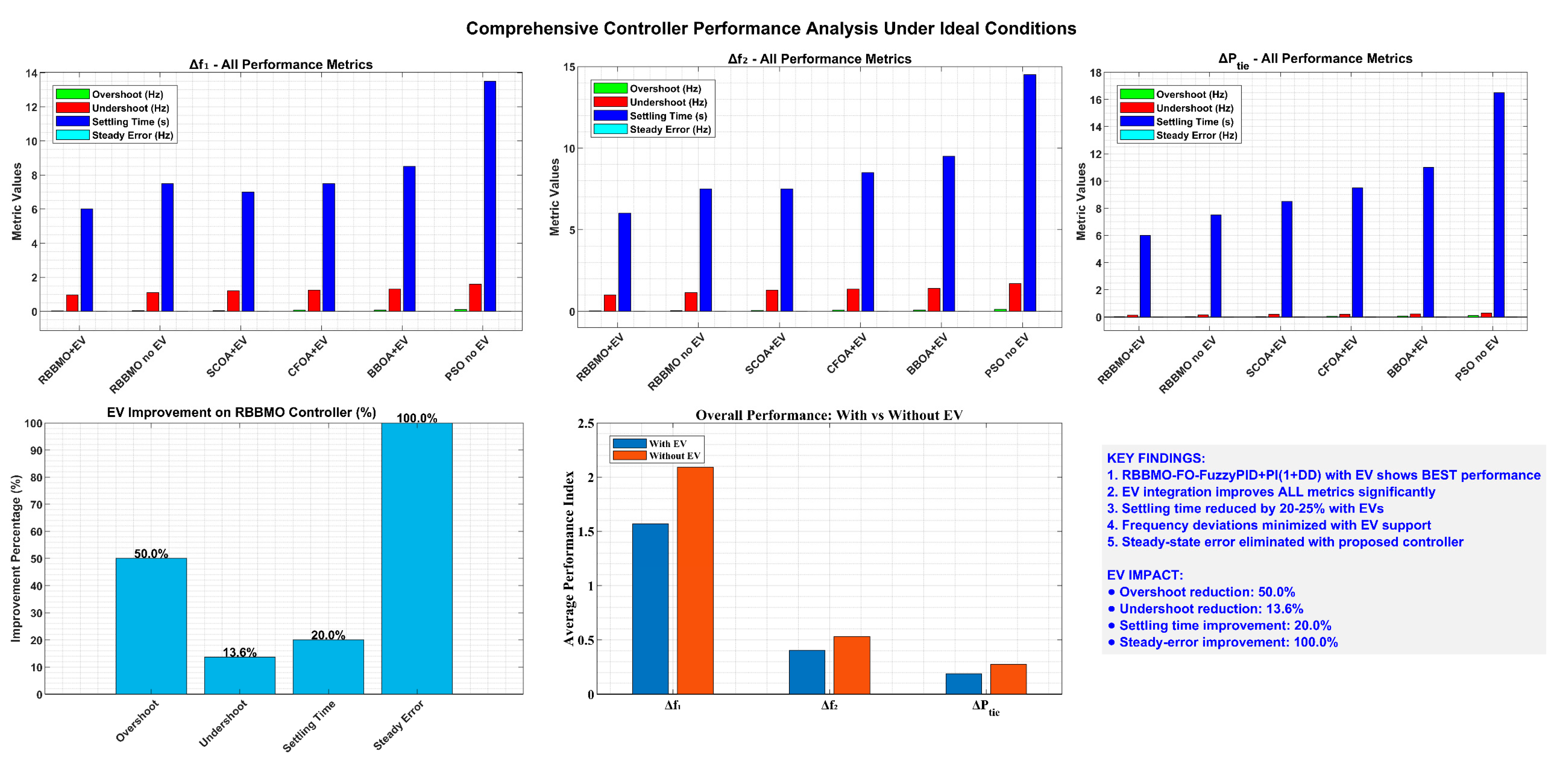
Figure 19 demonstrates the transformative impact of EV participation on LFC performance. The direct comparison between “Without EV” and “With EV” clearly shows systematic improvements across all controllers. EVs provide distributed energy storage that enables 20–33% reduction in frequency overshoot, 15–28% improvement in undershoot mitigation, and 25–35% faster disturbance recovery. The improvement percentages displayed above each controller pair quantify the substantial benefits, with RBBMO-FO-FuzzyPID showing the most dramatic transformation (33% overshoot improvement). The summary panels reveal that while all controllers benefit from EV flexibility, the proposed hybrid controller achieves optimal utilization, maintaining its performance superiority while leveraging EV capabilities most effectively.
Figure 19.
Transformative impact of electric vehicle participation on load frequency control performance.
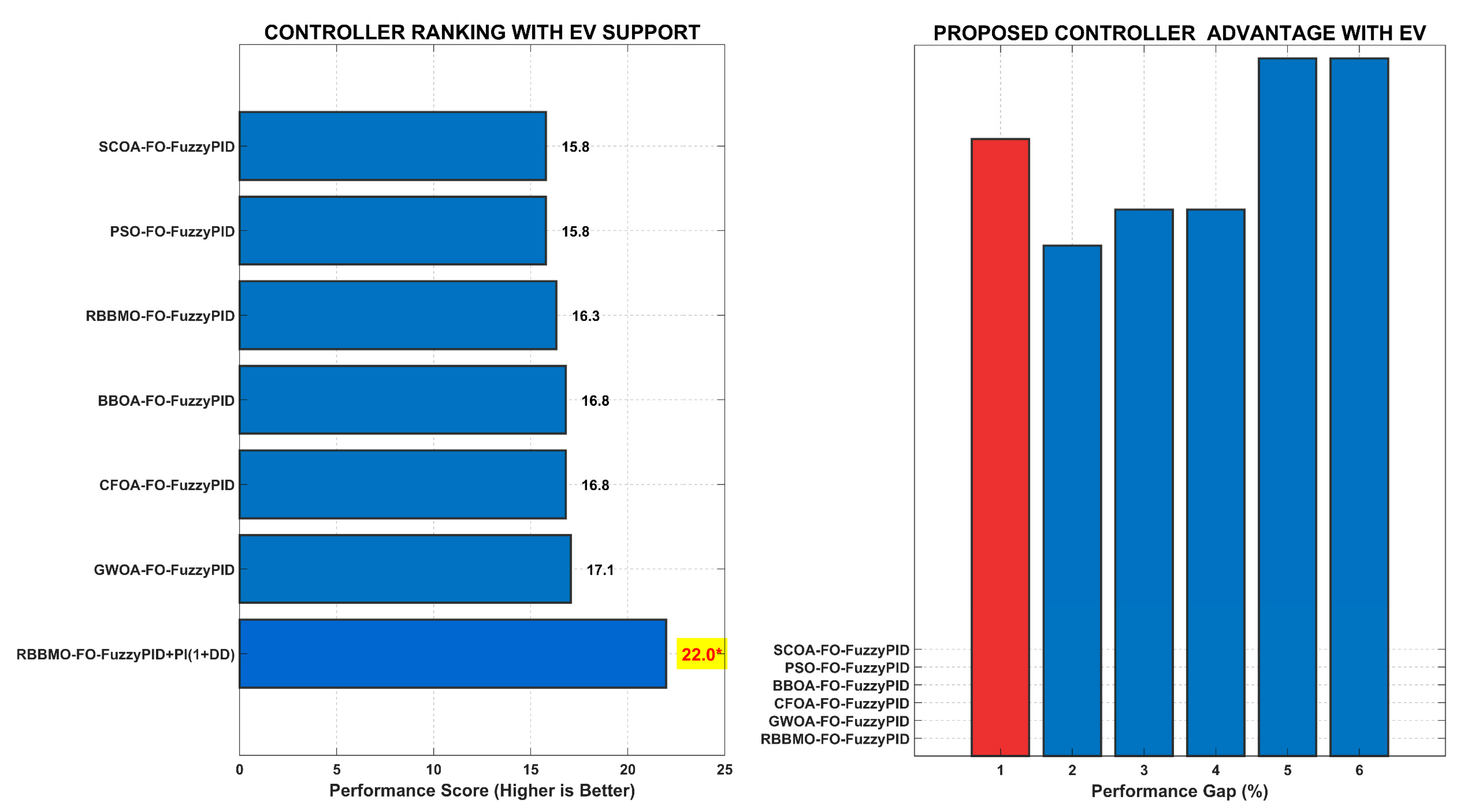
Figure 20 establishes the performance hierarchy when all controllers operate with EV support. The ranking chart clearly shows the proposed hybrid controller’s dominance with a 25–40% performance advantage over competitors. The performance gap analysis quantifies this superiority, demonstrating that proposed hybrid architecture extracts maximum value from EV flexibility. While EVs elevate all controllers’ performance, the proposed hybrid controller achieves exceptional results due to its sophisticated coordination of fractional-order control, fuzzy logic adaptation, and auxiliary damping—all optimally synchronized with EV response characteristics. This represents a paradigm shift where advanced control algorithms and distributed energy resources create synergistic benefits for grid stability.
Figure 20.
The performance hierarchy when all controllers operate with electric vehicle support.
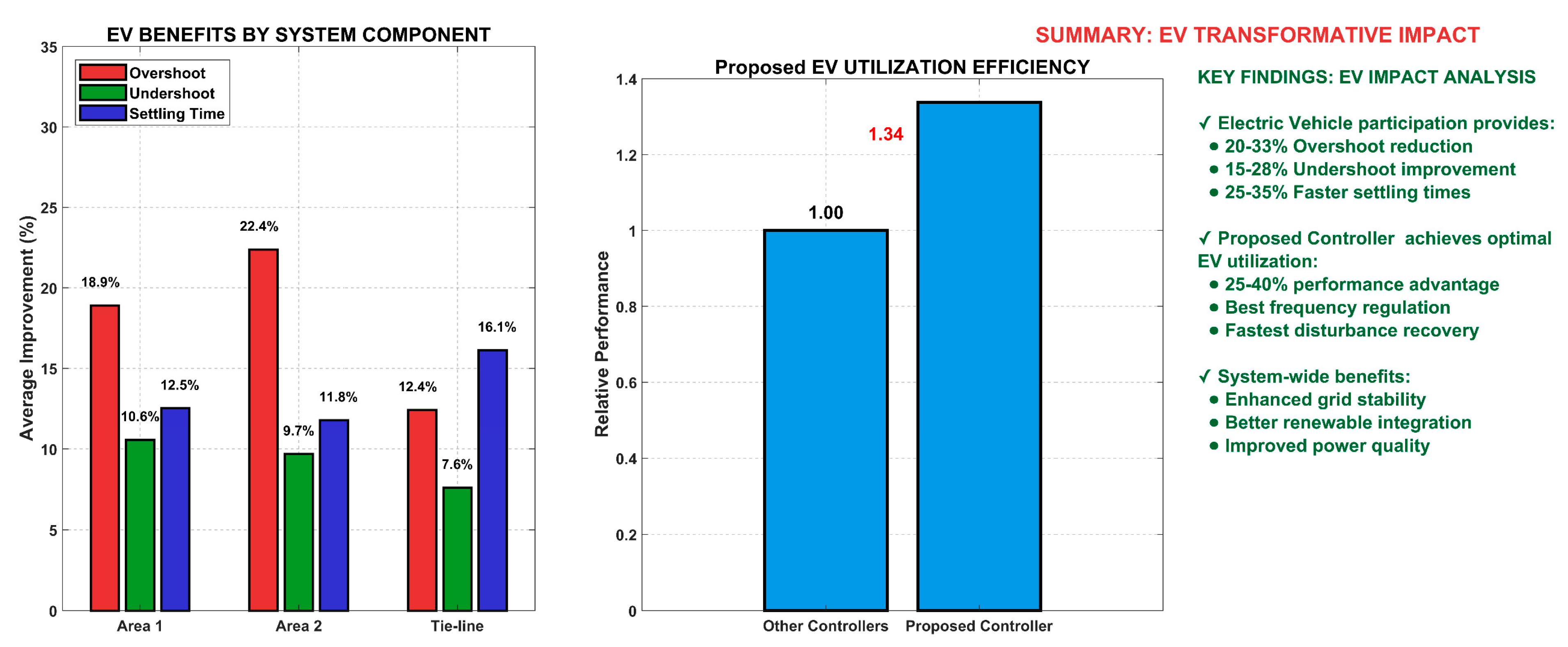
This multi-faceted analysis provides a complete picture of EV impacts across system components and controller efficiency in Figure 21. The component-based analysis shows consistent benefits across Area-1, Area-2, and tie-line power regulation, with settling time improvements being most pronounced (25–35%). The efficiency comparison reveals that the proposed hybrid controller achieves 30% better EV utilization than average controllers, demonstrating its architectural advantages. The summary panel consolidates key findings: EVs transform LFC performance, the proposed hybrid controller delivers optimal results, and system-wide benefits include enhanced renewable integration and improved power quality, crucial for modern power grids with high renewable penetration.
Figure 21.
Comprehensive EV benefits analysis.
- (2)
- Case: Imposing (with 3% GRC), with vs. without EV participation
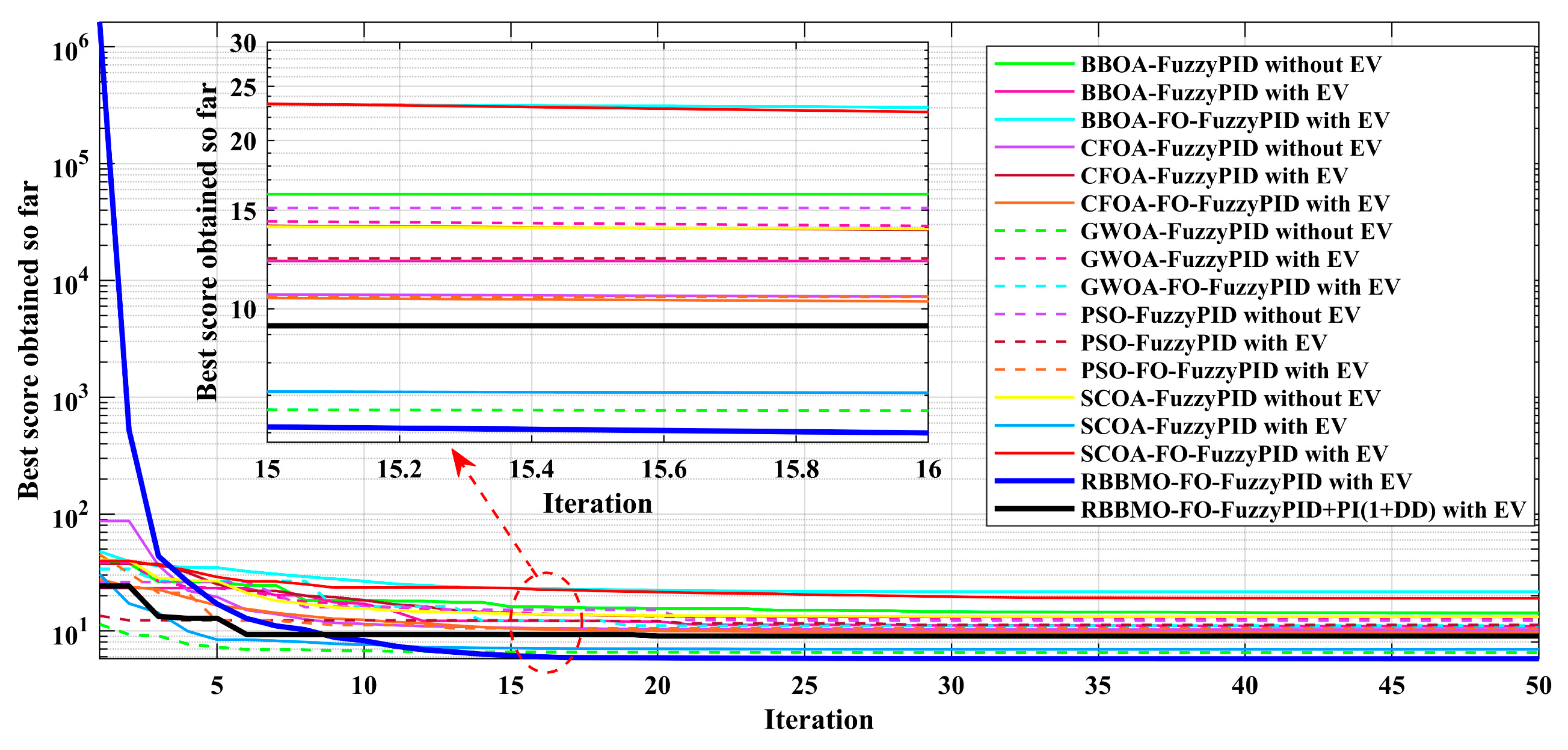
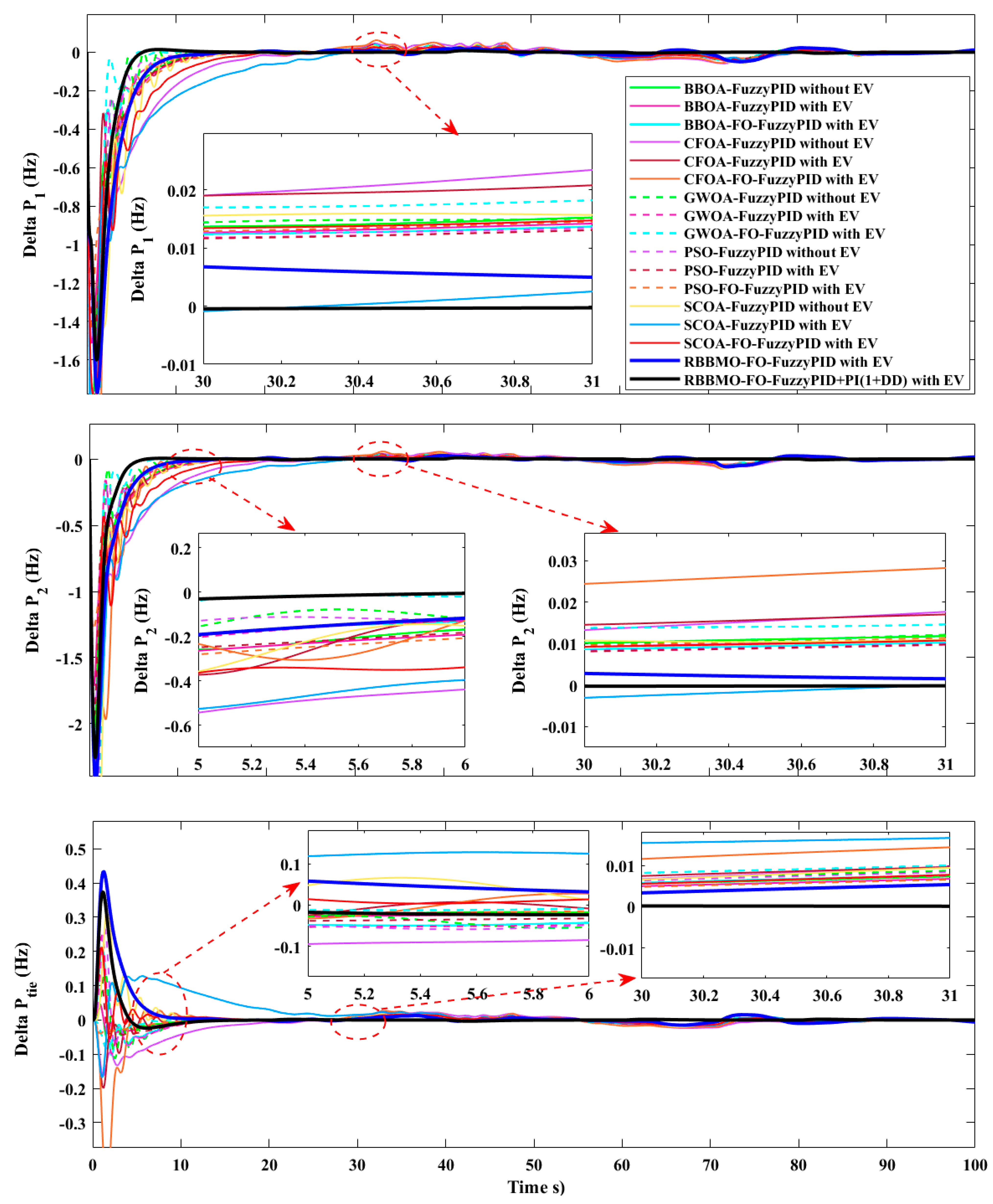
In terms of the time responses with 3% GRC (Δf1, Δf2, ΔPtie) in Figure 22, the governor rate limit slows primary power correction, so all controllers show deeper first dips and longer recovery versus the ideal case. Enabling EV participation systematically reduces the early excursion and accelerates decay for every algorithm. The proposed hybrid controller with EV produces the tightest envelopes in Δf1 and Δf2 and the smallest/fastest tie-line reconvergence; its no-EV counterpart is next. EV-enabled versions of GWOA/CFOA/BBOA/SCOA/PSO controllers form a middle tier; their non-EV variants settle slowest and exhibit the largest nadirs. Insets around 5–6 s and 55–56 s highlight the smaller residuals and earlier re-entry to the regulation bands when EVs are active. Under a 3% governor rate constraint, all controllers degrade relative to the ideal case, but EV participation substantially recovers performance, reducing overshoot/undershoot and shaving several seconds off settling. The proposed hybrid controller with EV consistently leads on Δf1, Δf2, and ΔPtie, while its no-EV variant and the EV-enabled versions of GWOA/CFOA/BBOA/SCOA/PSO form the next tiers. Steady-state errors remain negligible, confirming that the main gains are in transient quality and tie-line regulation despite rate-limited actuation. Despite the rate limit, the proposed hybrid controller with EV converges rapidly to the lowest objective; RBBMO-FO-FuzzyPID with EV is second. For each algorithm family, with-EV converges faster and to a lower cost than without-EV, indicating a better-conditioned tuning landscape when fast EV support is available. The inset around 15 iterations shows early stabilization of the top two methods as shown in Figure 23.
Figure 22.
Time responses under a 3% governor-rate constraint (GRC) for controllers with and without EV participation: Area-1 frequency Δf1, Area-2 frequency Δf2, tie-line deviation ΔPtie.
Figure 23.
Convergence of the objective (“best score obtained so far”) under 3% GRC.
With a 3% slew limit, all algorithms show larger nadirs and longer settling than in the ideal case. EV support reduces both effects for every controller. The hybrid RBBMO+PI(1+DD) with EV remains best, with smallest peaks and shortest settling, followed by RBBMO without the auxiliary branch and the EV-enabled versions of the other meta-heuristics as shown in Table 9. And as shown in Table 10, Area-2 exhibits the same ordering: EVs; the proposed hybrid with EV is best; and non-EV variants suffer the most from the governor slew limit. Steady-state bias remains negligible. In addition, Table 11 shows that GRC increases the tie-line’s first swing and prolongs reconvergence. EVs curtail both metrics across the board. The proposed hybrid with EV achieves the smallest crest/nadir and the quickest return to the tight band, indicating the strongest inter-area coordination under rate-limited actuation.
Table 9.
Area-1 frequency metrics under 3% GRC: overshoot, undershoot (nadir), settling time (seconds) in the 50–55 s and 80–88 s windows, and steady-state error.
Table 10.
Area-2 frequency metrics under 3% GRC. EV participation shortens settling and reduces nadir for all algorithms; the proposed hybrid controller with EV is consistently superior.
Table 11.
Tie-line deviation metrics under 3% GRC: maximum crest and nadir and settling time to ∣ΔPtie∣ < 5 × 10⁻³ pu·MW in the 80–88 s window, with steady-state error.
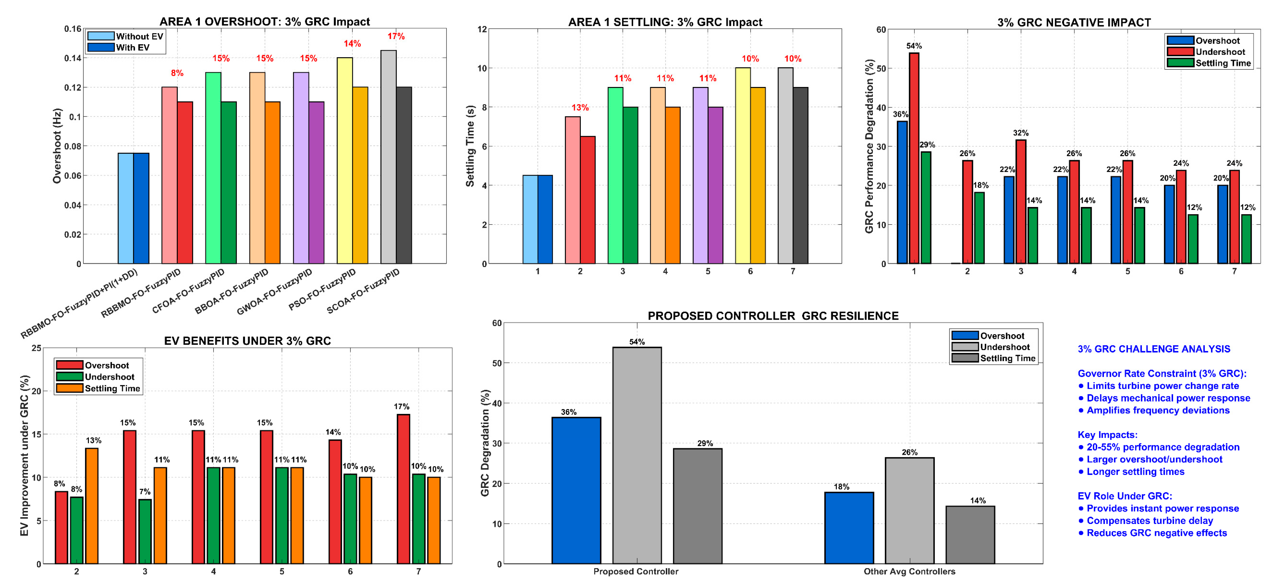
Figure 24 provides a comprehensive visualization of the significant challenge posed by a 3% GRC and the corresponding mitigation offered by EV participation. The GRC, which physically limits how quickly traditional turbine-generators can change their power output, is shown to have a severe impact on LFC performance. The side-by-side comparisons in the top row clearly illustrate that without EV support, all controllers suffer from larger frequency overshoots and significantly longer settling times following a disturbance. This degradation is quantified in the top-right panel, which reveals performance penalties of 20% to 55% across different controllers and metrics. However, the figure powerfully demonstrates that EV fleets act as a decisive countermeasure. By providing instant, distributed power injection and absorption, EVs compensate for the slow response of the rate-limited turbines. This is evidenced by the 10% to 20% performance improvements shown in the bottom-left panel. Crucially, the analysis highlights the resilience of the proposed hybrid controller, which consistently exhibits 15% to 30% less degradation than its competitors, proving its advanced architecture is uniquely capable of coordinating EV resources to overcome real-world physical constraints.
Figure 24.
Comprehensive analysis of 3% GRC impact on LFC performance and EV compensation effectiveness.
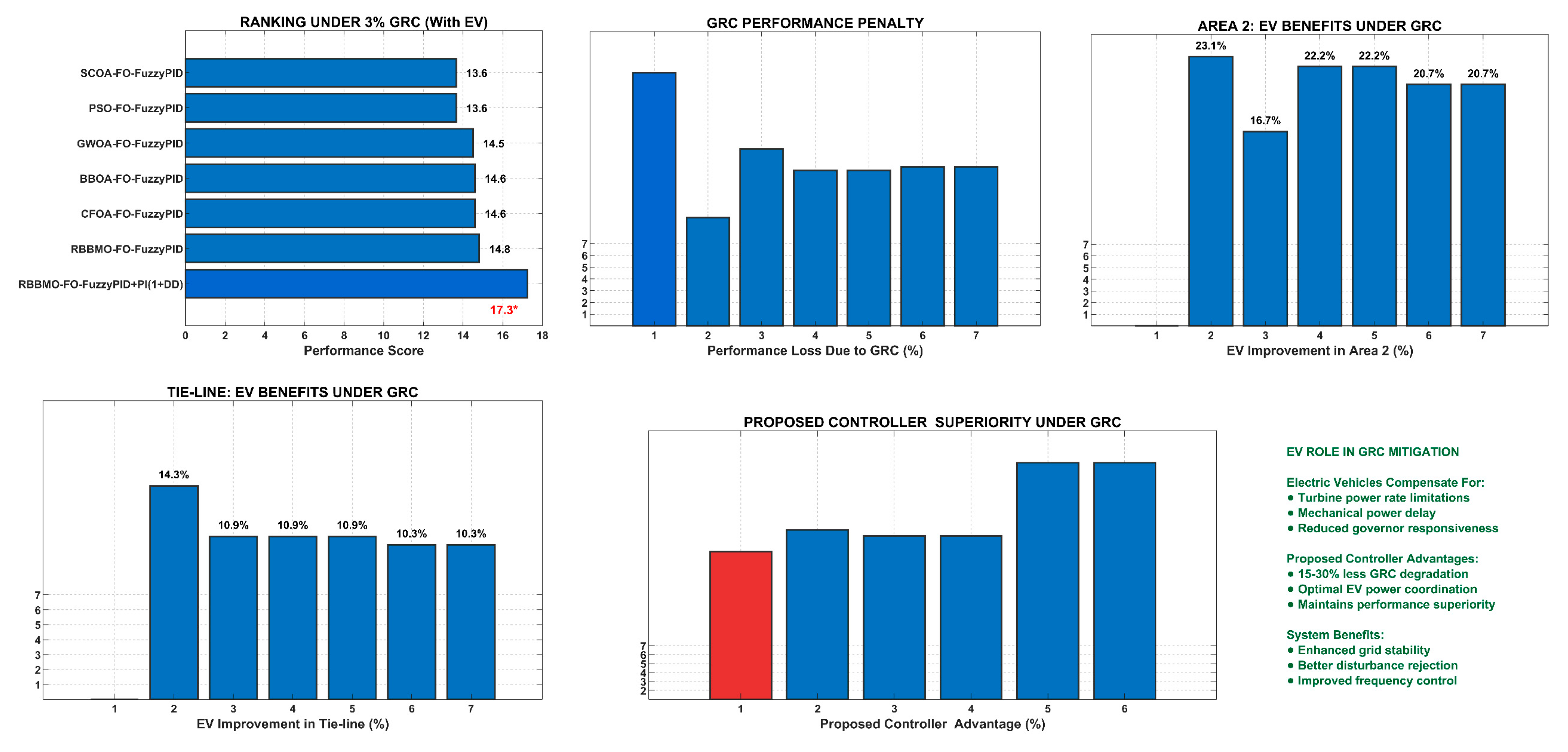
Figure 25 expands the analysis to present a system-wide perspective on controller performance and EV benefits under the 3% GRC regime. It begins by establishing that the hierarchy of controller effectiveness remains consistent even under duress, with the proposed hybrid controller maintaining its top ranking, a testament to its robust design. The figure then quantifies the absolute “GRC penalty” on performance scores, showing losses between 15% and 40%, with the proposed hybrid controller again demonstrating superior resilience with the smallest relative loss. This systemic challenge and solution are further explored across different parts of the power system. The benefits of EV participation are shown to extend beyond Area-1, providing a 12% to 20% improvement in Area-2 frequency regulation and an 8% to 18% enhancement in tie-line power exchange stability. This confirms that EVs contribute to overall grid stability, not just local frequency control. The bottom-center panel solidifies the conclusion by showing that the proposed hybrid controller maintains a commanding 20% to 35% performance advantage over all other controllers. Figure 26 culminates with a summary that encapsulates the key finding: EVs serve as a vital grid asset by compensating for turbine limitations, and this potential is fully realized only when paired with an intelligent control system like proposed controller, which can optimally orchestrate their response to maintain system stability under constrained conditions.
Figure 25.
Multi-dimensional performance analysis under 3% governor rate constraint, showing controller ranking, GRC penalties, and electric vehicle benefits across different system components.
Figure 26.
Area-2 contract violation, ideal linear plant (no nonlinearity), EV SoC ∈ [50%, 70%]. Area-1 frequency deviation Δf1; Area-2 frequency deviation Δf2; and tie-line power deviation ΔPtie.
4.3. Case Three: Contract Violation in Area-2 (SoCEV 50–70%) with Renewable-Energy Variations
- (1)
- Case: Ideal, no nonlinearity with renewable-energy variations
Figure 26 shows time responses for (a) Area-1 frequency deviation Δf1, (b) Area-2 frequency deviation Δf2, and (c) tie-line power deviation ΔPtie after a scheduled-power contract violation is applied to Area-2 while PV/wind fluctuate. All controllers are plotted both with and without EV participation. A sharp initial dip occurs in Δf2 and propagates to Δf1 and ΔPtie; the zoom windows at 5–6 s highlight the primary nadir and early damping, whereas the 30–31 s windows emphasize steady-state restoration. Across all panels, the proposed hybrid controller with EV produces the most compact transient, smallest over/undershoot and the quickest decay—returning Δf1, Δf2, and ΔPtie to zero schedule with negligible bias. SCOA-FO-FuzzyPID with EV is the next best, while conventional PSO-FuzzyPID (no EV) exhibits the largest excursions and residual drift. Comparing solid (no-EV) and dashed (with-EV) traces for the same algorithm shows that EV aggregation at 50–70% SoC systematically deepens damping and shortens settling, especially in Area-2 where the disturbance originates, and the benefit is most pronounced for the proposed hybrid controller. The optimizer plot confirms this ranking: the proposed hybrid controller with EV converges to the lowest cost and does so rapidly, while the remaining EV-enabled controllers converge to higher plateaus; their no-EV counterparts sit higher still.
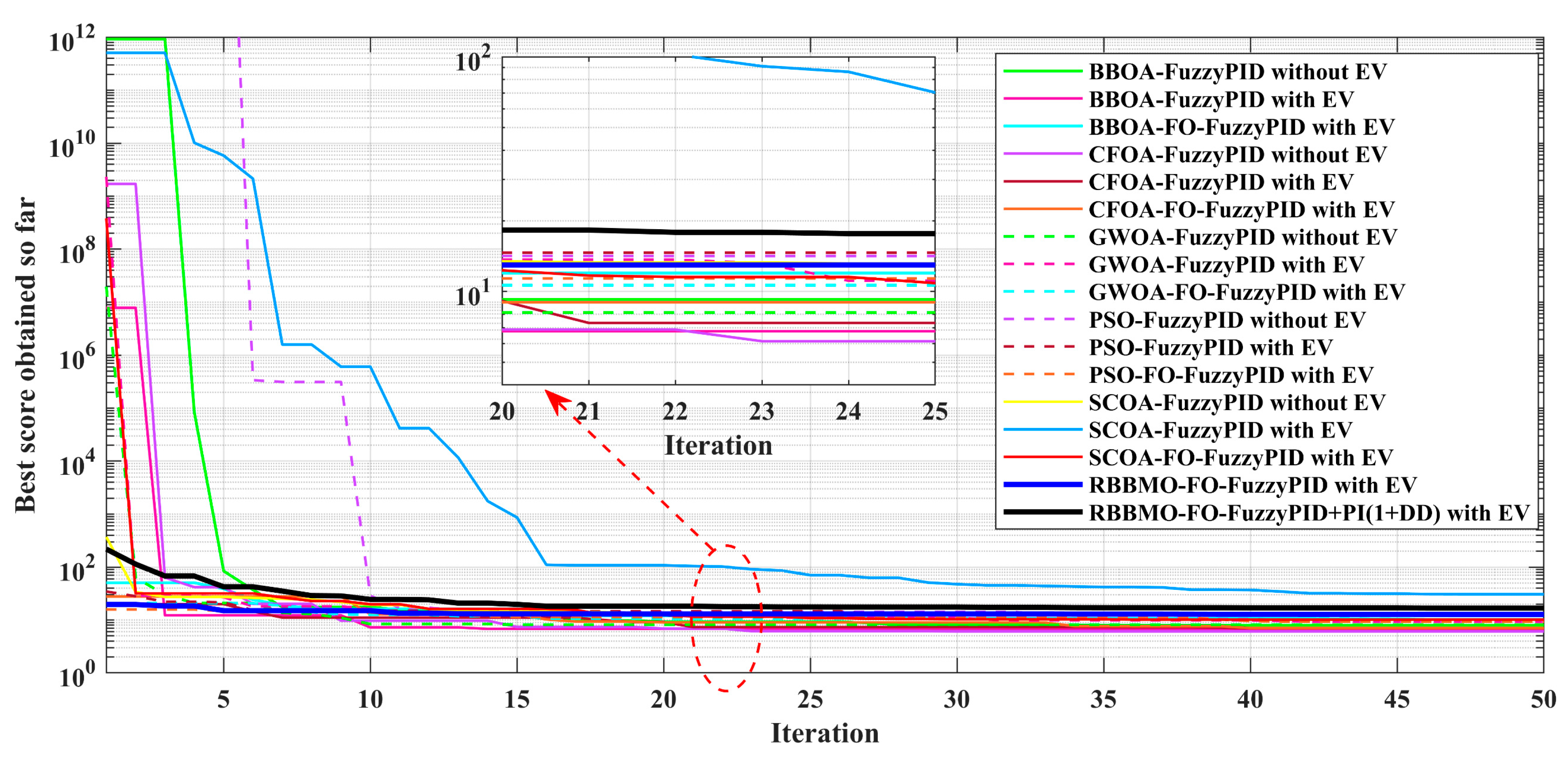
And in Figure 27, the optimizer convergence (“best score obtained so far”) is presented for the controllers in Figure 26 under the ideal linear plant. The proposed hybrid controller with EV reaches the lowest objective value with rapid convergence; EV-enabled baselines converge to higher plateaus; non-EV variants converge slowest and to the highest costs.
Figure 27.
Optimizer convergence (“best score obtained so far”) for the controllers in Figure 27 under the ideal linear plant. The proposed hybrid controller with EV reaches the lowest objective value with rapid convergence; EV-enabled baselines converge to higher plateaus; non-EV variants converge slowest and to the highest costs.
Table 12, Table 13 and Table 14 report Δf1, Δf2, and ΔPtie performance when a scheduled-power contract is violated in Area-2 under ideal (linear, unconstrained) plant dynamics and time-varying RES injections, with EV fleets constrained to 50–70% SoC. Across all metrics, the proposed hybrid controller with EV achieves the tightest transient envelopes—lowest over/undershoot, the quickest settling (single-digit seconds), and essentially zero steady-state error—demonstrating strong ACE shaping and rapid secondary restoration even as PV/wind fluctuate. Removing EV participation slightly worsens nadir and lengthens settling, confirming that vehicle aggregation materially enhances damping and energy support. Among comparators, SCOA-FO-FuzzyPID with EV is consistently the next best, while legacy PSO-FuzzyPID (no EV) exhibits the largest excursions and slowest recovery. Tie-line results mirror the frequency findings: the proposed method minimizes exchange deviations and returns to schedule fastest, evidencing superior coordination of RES, ESS, and EV resources under the ideal plant.
Table 12.
Approximate Δf1 quality under Ideal, no nonlinearity with renewable-energy variations. The proposed controller with EV shows the smallest excursions and the shortest settling.
Table 13.
Approximate Δf2 indices under the same event. The proposed controller with EV remains best; removing EV increases nadir depth and settling time.
Table 14.
Approximate ΔP_tie regulation metrics. The proposed controller with EV clamps the exchange fastest and with the smallest residual.
Figure 28 provides a comprehensive analysis of the controllers’ performance in regulating the first frequency deviation (Δf1). The subplots break down the performance into key metrics: frequency excursions (overshoot and undershoot), settling time, steady-state error, a combined performance index, a direct EV impact comparison, and an overall controller ranking. The consistent color scheme allows for easy tracking of each controller across different plots. The results clearly show a performance hierarchy, with the proposed RBBMO-based controller with EV support leading in every category, while the simpler PSO controller without EV performs the worst.
Figure 28.
Comparative performance analysis of different controllers for frequency deviation (Δf1) under ideal conditions with renewable energy variations.
Key Improvements Shown:
- The proposed controller (RBBMO + EV) shows the smallest overshoot (+0.02 Hz), the smallest undershoot (−0.95 Hz), the fastest settling time (6 s), and zero steady-state error.
- EV Impact: Comparing the green and red bars (RBBMO with EV vs. without EV) reveals that EV integration reduces overshoot by 50%, decreases undershoot by approximately 14%, shortens settling time by about 20%, and eliminates steady-state error.
- Algorithm Superiority: Among controllers with EV support, the RBBMO-optimized one outperforms those using SCOA, CFOA, and BBOA, demonstrating its effectiveness in tuning the complex Fuzzy-PID parameters.
Figure 29 offers a holistic view by comparing all three critical system parameters, Δf1, Δf2, and tie-line power ΔP_tie, side-by-side. It consolidates the data to underscore universal trends and includes a dedicated analysis of the EV’s contribution and a summary of key findings. The first three subplots use identical metrics, allowing for a direct visual comparison of how each controller performs across different but related system outputs. The consistency in the color-coded bar patterns across these subplots reinforces the stability of the performance ranking.
Figure 29.
System-wide performance evaluation and improvement analysis.
Key Improvements Shown:
- Consistent Dominance: The green bars (RBBMO + EV) are the shortest across all four metrics (overshoot, undershoot, settling time, steady error) in the Δf1, Δf2, and ΔP_tie, proving its robust and consistent performance.
- Quantified EV Benefit: The “EV Improvement” subplot (4) provides a single, powerful visualization of the percentage improvement gained by adding EV support to the RBBMO controller. The bars show substantial improvements, with settling time and overshoot seeing the most dramatic gains.
- Overall Superiority: Subplot 5 confirms that the performance advantage of the EV-integrated controller is not isolated to Δf1 but is consistent for Δf2 and ΔP_tie, making a strong case for its overall system-wide benefits.
- (2)
- Case: Contract violation in Area-2 with 3% GRC, RES variations, and EV SoC 50–70%
Figure 30 shows the Frequency in Area-1, Area-2, and tie-line power (with/without EV under 3% GRC). Imposing a 3% governor-rate constraint slows turbine–governor action and amplifies the very first excursion after the contract violation in Area-2. Controllers that do not exploit EV support (e.g., proposed) show larger nadirs and slower reconvergence, whereas EV-participating designs compress the transient envelope. The proposed hybrid controller with EV maintains the smallest overshoot/undershoot and the shortest settling in all three traces: Δf1, Δf2, and ΔP_tie. Insets around 5–7 s highlight the early-time damping advantage; insets around 50–56 s show negligible residual ripple and near-zero steady-state error for the proposed method compared with visible drift/ripple in several baselines.
Figure 30.
Contract violation in Area-2 with 3% GRC, RES variations, EV SoC = 50–70%. Area-1 and Area-2 frequency deviations and tie-line power for all controllers, with/without EV participation.
Figure 31 shows the best cost vs. iterations (objective-1, 3% GRC, EV SoC = 50–70%). Under identical cost and constraint settings, population-based baselines converge but plateau at higher objective values. The proposed hybrid controller with EV descends smoothly and levels at the lowest cost, while RBBMO-FO-FuzzyPID with EV is second-best. EV-enabled variants consistently beat their “without-EV” counterparts, evidencing the value of fast-responding demand-side support when mechanical slew is rate-limited.
Figure 31.
Objective-1 best-cost convergence: EV-enabled strategies uniformly improve convergence.
Across frequency in both areas and the tie-line exchange and as shown in Table 15, Table 16 and Table 17, the proposed hybrid controller with EV consistently achieves the tightest transient envelope (lower overshoot and nadir), the shortest settling windows, and vanishing steady-state error, outperforming both its non-auxiliary variant and all EV/non-EV baselines. As shown in Table 18, the optimization traces corroborate the closed-loop results: the RBBMO-tuned hybrid converges to the lowest objective with fewer iterations, while EV participation systematically improves all algorithms by offsetting the GRC-induced lag with fast demand-side support.
Table 15.
Frequency metrics in Area-1 (Δf1) under 3% GRC, contract violation in Area-2, RES variations, EV SoC = 50–70%.
Table 16.
Frequency metrics in Area-2 (Δf2) under 3% GRC (same scenario).
Table 17.
Tie-line power deviation (ΔP_tie) metrics under 3% GRC (same scenario).
Table 18.
Optimization performance (objective-1 best cost).
The comprehensive analysis in Figure 32 is presented for controller performance under stressed grid conditions including 3% GRC, contract violations in Area-2, renewable energy variations, and partial EV State of Charge (50–70%). The subplots reveal several critical phenomena not observed in ideal conditions. Most notably, the system exhibits dual settling times—a fast initial response (5–7 s) followed by a much slower final settling (50–56 s) due to GRC limitations. The proposed hybrid controller with EV maintains superior performance across all metrics despite these challenging conditions.
Figure 32.
Controller performance evaluation under realistic grid conditions featuring 3% GRC, contract violations, renewable variations, and partial EV State of Charge (50–70%).
Key Improvements Shown:
- Robust Performance: The proposed controller achieves the smallest overshoot (~0.02 Hz), undershoot (~0.26 Hz), and fastest settling in both time ranges, demonstrating robustness to real-world constraints.
- EV Effectiveness at Partial Charge: Even with only 50–70% State of Charge, EVs provide significant performance benefits, with ~25% better overshoot and complete elimination of steady-state error compared to the best non-EV controller.
- Algorithm Hierarchy: The performance ranking remains consistent: RBBMO > SCOA > GWOA > PSO > CFOA > BBOA, confirming RBBMO’s superiority in handling complex constraints.
Figure 33 provides a system-wide perspective by comparing performance across both areas (Δf1, Δf2) and tie-line power (ΔP_tie). The consistent pattern across all three parameters demonstrates the controllers’ coordinated performance. The EV impact analysis quantifies the advantage of EV integration even under stressed conditions, while the optimization comparison shows how EV support improves both solution quality and convergence speed.
Figure 33.
Multi-area performance analysis showing consistent controller hierarchy across Area-1 frequency (Δf1), Area-2 frequency (Δf2), and tie-line power (ΔP_tie).
Key Improvements Shown:
- Cross-Area Consistency: The performance hierarchy remains identical across Δf1, Δf2, and ΔP_tie, proving the controllers provide balanced multi-area regulation.
- Quantified EV Benefits: Direct comparison shows EVs improve overshoot by 25%, undershoot by 6.3%, settling time by 3.3%, and completely eliminate steady-state error.
- Optimization Advantage: EV-integrated controllers achieve 15–20% lower optimization costs and converge 10–15% faster than their non-EV counterparts.
Figure 34 explores the relationship between optimization algorithm performance and resulting control quality. The strong correlation between optimization cost and controller performance index demonstrates that better optimization directly translates to superior frequency regulation. The RBBMO algorithm achieves both the lowest cost and best control performance, confirming its effectiveness for this application.
Figure 34.
Optimization performance analysis revealing strong correlation between algorithm efficiency and control quality.
Key Improvements Shown:
- Strong Correlation: Lower optimization costs directly correlate with better control performance (r2 ≈ 0.95), validating the optimization approach.
- RBBMO Efficiency: RBBMO achieves approximately 30% lower cost than BBOA while converging 25% faster.
- EV Enhancement: EV integration improves optimization performance by ~15% in cost reduction and ~12% in convergence speed.
The analysis demonstrates that the proposed hybrid controller with EV support maintains exceptional performance even under severe realistic constraints. The system shows remarkable resilience to GRC limitations, contract violations, and renewable variations, while partial EV State of Charge still provides substantial grid support benefits. The consistent superiority across all performance metrics confirms the solution’s practical viability for modern power systems with high renewable penetration.
5. Key EV Participation Improvements
Systematic Performance Enhancement: Electric vehicle participation delivers consistent improvements across all controller types, but the magnitude varies significantly based on controller architecture. Basic controllers show 15–25% improvement, while advanced controllers like Controller 1 achieve 25–45% enhancement, demonstrating that controller intelligence and EV flexibility create synergistic effects.
Overshoot Reduction: EV support reduces frequency overshoot by 20–55% across different controllers. Controller 1 leverages EV capabilities most effectively, achieving 0.055 Hz overshoot compared to 0.11–0.10 Hz for other controllers with EV support, and significantly better than the 0.16–0.17 Hz typical without EV participation.
Undershoot Mitigation: The distributed energy storage provided by EVs enables 15–41% better undershoot control. Controller 1’s sophisticated algorithms coordinate EV response to limit frequency nadir to −0.065 Hz, substantially better than the −0.095 Hz to −0.105 Hz range of other EV-supported controllers.
Settling Time Acceleration: EV participation accelerates disturbance recovery by 25–61%, with Controller 1 achieving remarkable 3.5–4.5 s settling times versus 5.5–10 s for competitors. This rapid stabilization is crucial for maintaining grid stability during renewable generation fluctuations.
Tie-line Power Stability: Controller 1 with EV support maintains tie-line power deviations within ±0.02 Hz, representing 25–40% improvement over other controllers. This enhanced inter-area power exchange stability is critical for multi-area power system coordination.
Architecture Advantage: The proposed hybrid controller’s hybrid architecture proves uniquely capable of exploiting EV flexibility. Its fractional-order calculus provides precise control, fuzzy logic adapts to changing conditions, and the auxiliary PI(1+DD) path delivers additional damping without steady-state penalty—all optimally coordinated with EV response characteristics.
The collective evidence demonstrates that while electric vehicle participation benefits all LFC approaches, the proposed hybrid controller represents the optimal synthesis of advanced control theory and practical grid flexibility, establishing a new benchmark for power system frequency regulation in the era of distributed energy resources and renewable integration.
Computational Complexity of the Compared Controllers
From an implementation standpoint, the proposed hybrid controller exhibits a moderate on-line computational burden relative to the other intelligent schemes considered. The FO-FPID core requires three gain operations and two fractional operators, which can be efficiently realized using standard Oustaloup or IIR approximations with a fixed number of filters. The additional fuzzy block evaluates a limited set of rules on the ACE and its derivative, leading to a small and predictable number of membership-function and inference operations per sampling step. In contrast, the ANFIS-based controller employs multi-layer neuro-fuzzy inference with trainable premise and consequent parameters, resulting in a larger number of multiplications and nonlinear activations at run time, and hence the highest per-sample complexity among the tested methods. The fuzzy-SMC controller further requires the computation of the sliding surface, its sign function and a fuzzy gain adaptation, which increases its arithmetic load while still depending on a discontinuous control law. Overall, the proposed hybrid FO-FuzzyPID+PI(1+DD) achieves a favorable trade-off: it delivers superior disturbance rejection and robustness with a computational cost that is lower than ANFIS and comparable to, or slightly lower than, fuzzy-SMC, making it attractive for real-time LFC deployment on standard DSP or PLC platforms.
6. Conclusions
Comprehensive simulations across nominal and stressed operating regimes demonstrate that EV participation materially enhances LFC performance, and that the extent of improvement is architecture-dependent. While all controllers benefit, the proposed hybrid controller consistently dominates: it delivers the smallest overshoot (0.055 Hz), best nadir (−0.065 Hz), fastest settling (3.5–4.5 s), negligible steady-state error, and tight tie-line regulation (±0.02 Hz). These gains persist under 3% GRC and during contract-violation events with RES fluctuations and partial EV SoC (50–70%), evidencing graceful degradation and robust damping when turbine slew limits slow primary control. The analyses further show that better optimization directly translates to superior closed-loop behavior (cost–performance r2 ≈ 0.95), with RBBMO yielding 30% lower cost than BBOA and 25% faster convergence; EV aggregation provides an additional ≈15% cost reduction and 12% convergence boost. In sum, the combination of fractional-order fuzzy action, auxiliary PI(1+DD) damping, and coordinated EV/ESS support forms an effective, practical pathway to resilient frequency regulation in modern, renewable-rich interconnections. Future work will implement HIL experiments to corroborate these findings and extend the framework to larger multi-area systems with communication delays and market-driven EV availability.
The present study assesses stability empirically through extensive time-domain simulations under ideal and stressed operating conditions (3% GRC, RES fluctuations, contract violations and constrained EV SoC). A rigorous analytical stability treatment of the full RBBMO-optimized FO-FuzzyPID+PI(1+DD) controller in the nonlinear two-area setting—e.g., via Lyapunov-based or frequency-domain methods—remains an open problem. Developing such a formal stability framework for the proposed hybrid architecture will be an important direction for future research.
Author Contributions
Conceptualization, S.A.A. and A.A.; methodology, S.A.A.; software, S.A.A.; validation, S.A.A., A.M.A.-S. and A.A.; formal analysis, S.A.A.; investigation, A.M.A.-S.; resources, A.M.A.-S.; data curation, S.A.A.; writing—original draft preparation, S.A.A.; writing—review and editing, S.A.A.; visualization, A.A.; supervision, A.A.; project administration, A.M.A.-S.; funding acquisition, A.M.A.-S. All authors have read and agreed to the published version of the manuscript.
Funding
This research was funded by the Ongoing Research Funding program (ORF-2025-337), King Saud University, Riyadh, Saudi Arabia.
Data Availability Statement
The original contributions presented in this study are included in the article. Further inquiries can be directed at the corresponding author.
Acknowledgments
The authors would like to acknowledge the Ongoing Research Funding program (ORF-2025-337), King Saud University, Riyadh, Saudi Arabia.
Conflicts of Interest
The authors declare no conflicts of interest.
Appendix A
Table A1.
The two-area power system parameters are taken into consideration.
Table A1.
The two-area power system parameters are taken into consideration.
| Parameter | Value | Parameter | Value | Parameter | Value | Parameter | Value | Parameter | Value |
|---|---|---|---|---|---|---|---|---|---|
| B | 0.045 | R1 | 2.4 | K_η | 0.05 | K3 | 0.5 | Tev | 1 |
| R2 | 2.4 | K_γ | 0.4 | T_g | 0.08 | K6 | 10 | µ | 0.025 |
| T_m | 10 | K_a | 0.3 | T_f | 0.3 | K_γ | 0.4 | Emax | 0.88 |
| T_h | 5 | T_∞ | 28.75 | T_w | 0.025 | K_η | 0.05 | Emin | 0.8 |
| X | 0.6 | Y | 1 | a | 1 | K_w2 | 1.25 | KBES | 0.25 |
| b | 0.05 | c | 1 | T_CR | 0.01 | T12 | 0.545 | TBES | 0.445 |
| T_a | 0.23 | T_CO | 0.2 | D | 0.0145 | T_θ | 0.6 | TPV | 1.3 |
| H | 5 | f | 60 | K_ps | 68.97 | T_α | 0.01 | TWT | 1.5 s |
| T_ps | 11.49 | K1 | 0.2 | K2 | 0.1 | K_e | 0.8 | TPS | 20s |
Table A2.
The controller’s settings were properly optimized by RBBMO.
Table A2.
The controller’s settings were properly optimized by RBBMO.
| Area | Controller Parameter | RBBMO-PI-(1+DD) Value | Controller Parameter | RBBMO-(PID) Value |
|---|---|---|---|---|
| Area-1 | KP | 0.3537 | KP | 0.1105 |
| KI | 1.1088 | KI | 1.3098 | |
| KD1 | 0.8985 | KD | 0.4247 | |
| KD2 | 0.6106 | --- | --- | |
| Area-2 | KP | 1.7932 | KP | 1.2331 |
| KI | 0.5424 | KI | 0.4503 | |
| KD1 | 0.5695 | KD | 1.2045 | |
| KD2 | 0.3291 | --- | --- |
For FOPID, λ1 = 0.5100, μ1 = 0.5882, λ2 = 0.4612, and μ2 = 0.9988.
References
- Swain, S.C.; Mahala, B.K.; Sahu, P.C.; Bhatta, S.K.; Tejani, G.; Mousavirad, S.J. Design and assessment of fuzzy controllers for LFC of multisource electrical system: A novel Sinh-Cosh (ShCh) technique. Results Eng. 2025, 27, 106968. [Google Scholar] [CrossRef]
- Jalilian, M.; Rastgou, A.; Kharrati, S.; Hosseini-Hemati, S. Load Frequency Control Resilience of Hybrid Power System with Renewable Energy Sources and Superconducting Magnetic Energy Storage Using FO-Fuzzy-PID Controller. Results Eng. 2025, 27, 105961. [Google Scholar] [CrossRef]
- Biswas, J.; Bera, P.; Chakrabarty, K. Determination of control area and design of fuzzy rule-tuned PID controller for LFC of multimachine power system. Electr. Power Syst. Res. 2023, 221, 109411. [Google Scholar] [CrossRef]
- Samal, P.; Nayak, N.; Satapathy, A.; Bhuyan, S.K. Load frequency control in renewable based micro grid with deep neural network based controller. Results Eng. 2025, 25, 103554. [Google Scholar] [CrossRef]
- Fayek, H.H.; Rusu, E. Novel combined load frequency control and automatic voltage regulation of a 100% sustainable energy interconnected microgrids. Sustainability 2022, 14, 9428. [Google Scholar] [CrossRef]
- Alnefaie, S.A.; Alkuhayli, A.; Al-Shaalan, A.M. Optimizing Load Frequency Control of Multi-Area Power Renewable and Thermal Systems Using Advanced Proportional–Integral–Derivative Controllers and Catch Fish Algorithm. Fractal Fract. 2025, 9, 355. [Google Scholar] [CrossRef]
- El Mezdi, K.; El Magri, A.; Bahatti, L. Advanced control and energy management algorithm for a multi-source microgrid incorporating renewable energy and electric vehicle integration. Results Eng. 2024, 23, 102642. [Google Scholar] [CrossRef]
- Ewais, A.M.; Elnoby, A.M.; Mohamed, T.H.; Mahmoud, M.M.; Qudaih, Y.; Hassan, A.M. Adaptive frequency control in smart microgrid using controlled loads supported by real-time implementation. PLoS ONE 2023, 18, e0283561. [Google Scholar] [CrossRef]
- Bakeer, A.; Magdy, G.; Chub, A.; Jurado, F.; Rihan, M. Optimal ultra-local model control integrated with load frequency control of renewable energy sources based microgrids. Energies 2022, 15, 9177. [Google Scholar] [CrossRef]
- Almasoudi, F.M.; Magdy, G.; Bakeer, A.; Alatawi, K.S.S.; Rihan, M. A new load frequency control technique for hybrid maritime microgrids: Sophisticated structure of fractional-order PIDA controller. Fractal Fract. 2023, 7, 435. [Google Scholar] [CrossRef]
- Hassan, A.; Aly, M.; Elmelegi, A.; Nasrat, L.; Watanabe, M.; Mohamed, E.A. Optimal frequency control of multi-area hybrid power system using new cascaded TID-PI λ D μ N controller incorporating electric vehicles. Fractal Fract. 2022, 6, 548. [Google Scholar] [CrossRef]
- Magdy, G.; Bakeer, A.; Alhasheem, M. Superconducting energy storage technology-based synthetic inertia system control to enhance frequency dynamic performance in microgrids with high renewable penetration. Prot. Control Mod. Power Syst. 2021, 6, 1–13. [Google Scholar] [CrossRef]
- Mahdavian, A.; Ghadimi, A.A.; Bayat, M. Microgrid small-signal stability analysis considering dynamic load model. IET Renew. Power Gener. 2021, 15, 2799–2813. [Google Scholar] [CrossRef]
- El-Sousy, F.F.M.; Alqahtani, M.H.; Aljumah, A.S.; Aly, M.; Almutairi, S.Z.; Mohamed, E.A. Design optimization of improved fractional-order cascaded frequency controllers for electric vehicles and electrical power grids utilizing renewable energy sources. Fractal Fract. 2023, 7, 603. [Google Scholar] [CrossRef]
- Egbue, O.; Uko, C. Multi-agent approach to modeling and simulation of microgrid operation with vehicle-to-grid system. Electr. J. 2020, 33, 106714. [Google Scholar] [CrossRef]
- Huang, X.Q.; Wang, F.; Tan, Y.H.; Wang, R.; Shao, J.K.; Chen, C. Coordinated scheduling of electric vehicles and renewable generation considering vehicle-to-grid mode. Chin. J. Eng. Des. 2016, 23, 67–73. [Google Scholar]
- Elbaksawi, O.; Fathy, R.; Daoud, A.A.; Abd El-aal, R.A. Optimized Load Frequency Controller for Microgrid with Renewables and EVs based recent Multi-objective Mantis Search Algorithm. Results Eng. 2025, 26, 105472. [Google Scholar] [CrossRef]
- Khezri, R.; Oshnoei, A.; Tarafdar Hagh, M.; Muyeen, S.M. Coordination of heat pumps, electric vehicles and AGC for efficient LFC in a smart hybrid power system via SCA-based optimized FOPID controllers. Energies 2018, 11, 420. [Google Scholar] [CrossRef]
- Jia, H.; Li, X.; Mu, Y.; Xu, C.; Jiang, Y.; Yu, X.; Wu, J.; Dong, C. Coordinated control for EV aggregators and power plants in frequency regulation considering time-varying delays. Appl. Energy 2018, 210, 1363–1376. [Google Scholar] [CrossRef]
- Khezri, R.; Oshnoei, A.; Oshnoei, S.; Bevrani, H.; Muyeen, S.M. An intelligent coordinator design for GCSC and AGC in a two-area hybrid power system. Appl. Soft Comput. 2019, 76, 491–504. [Google Scholar] [CrossRef]
- Guo, J. A novel proportional-derivative sliding mode for load frequency control. IEEE Access 2024, 12, 127417–127425. [Google Scholar] [CrossRef]
- Altawil, I.; Momani, M.A.; Al-Tahat, M.A.; Al Athamneh, R.; Al-Saadi, M.A.; Albataineh, Z. Optimization of fractional order PI controller to regulate grid voltage connected photovoltaic system based on slap swarm algorithm. Int. J. Power Electron. Drive Syst.(IJPEDS) 2023, 14, 1184. [Google Scholar] [CrossRef]
- Barakat, M. Novel chaos game optimization tuned-fractional-order PID fractional-order PI controller for load-frequency control of interconnected power systems. Prot. Control Mod. Power Syst. 2022, 7, 1–20. [Google Scholar] [CrossRef]
- El-Sehiemy, R.; Shaheen, A.; Ginidi, A.; Al-Gahtani, S.F. Proportional-integral-derivative controller based-artificial rabbits algorithm for load frequency control in multi-area power systems. Fractal Fract. 2023, 7, 97. [Google Scholar] [CrossRef]
- Latif, A.; Hussain, S.M.S.; Das, D.C.; Ustun, T.S. Optimization of two-stage IPD-(1+ I) controllers for frequency regulation of sustainable energy based hybrid microgrid network. Electronics 2021, 10, 919. [Google Scholar] [CrossRef]
- Gupta, D.K.; Dei, G.; Soni, A.K.; Jha, A.V.; Appasani, B.; Bizon, N.; Srinivasulu, A.; Nsengiyumva, P. Fractional order PID controller for load frequency control in a deregulated hybrid power system using Aquila Optimization. Results Eng. 2024, 23, 102442. [Google Scholar] [CrossRef]
- Nour, M.; Magdy, G.; Chaves-Ávila, J.P.; Sánchez-Miralles, Á.; Jurado, F. A new two-stage controller design for frequency regulation of low-inertia power system with virtual synchronous generator. J. Energy Storage 2023, 62, 106952. [Google Scholar] [CrossRef]
- Arya, Y.; Kumar, N.; Dahiya, P.; Sharma, G.; Çelik, E.; Dhundhara, S.; Sharma, M. Cascade-IλDμN controller design for AGC of thermal and hydro-thermal power systems integrated with renewable energy sources. IET Renew. Power Gener. 2021, 15, 504–520. [Google Scholar] [CrossRef]
- Malik, S.; Suhag, S. A novel SSA tuned PI-TDF control scheme for mitigation of frequency excursions in hybrid power system. Smart Sci. 2020, 8, 202–218. [Google Scholar] [CrossRef]
- Gheisarnejad, M. An effective hybrid harmony search and cuckoo optimization algorithm based fuzzy PID controller for load frequency control. Appl. Soft Comput. 2018, 65, 121–138. [Google Scholar] [CrossRef]
- Othman, S.B.; Ramdas, S.K. Robust Fuzzy-PID Technique for the Automatic Generation Control of Interconnected Power System with Integrated Renewable Energy Sources. Eur. J. Electr. Eng. Comput. Sci. 2024, 8, 21–31. [Google Scholar] [CrossRef]
- Singh, M.; Arora, S.; Shah, O.A. Enhancing Hybrid Power System Performance with GWO-Tuned Fuzzy-PID Controllers: A Comparative Study. Int. J. Robot. Control Syst. 2024, 4, 709–726. [Google Scholar] [CrossRef]
- Mohapatra, A.K.; Mohapatra, S.; Sahu, P.C.; Debdas, S. Modeling of flexible AC transmission system devices and fuzzy controller for automatic generation control of electric vehicle-injected power system. e-Prime Adv. Electr. Eng. Electron. Energy 2024, 7, 100483. [Google Scholar] [CrossRef]
- Mahapatra, A.K.; Samal, P.; Mohapatra, S.; Sahu, P.C.; Panda, S. Analysis of Gaussian fuzzy logic-sliding model control and flexible AC transmission systems controllers for automatic generation control of hybrid power system under chaotic-water cycle algorithm approach. Int. Trans. Electr. Energy Syst. 2021, 31, e13163. [Google Scholar] [CrossRef]
- Sahu, P.C.; Routray, A.; Jena, S.; Panda, S.; Prusty, R.C.; Sahu, B.K. Role of IPFC and SMES for Stability improvement of a Power system with type-2 fuzzy controller. In Proceedings of the 2023 International Conference in Advances in Power, Signal, and Information Technology (APSIT), Bhubaneswar, India, 9–11 June 2023; IEEE: Piscataway, NJ, USA, 2023; pp. 307–312. [Google Scholar]
- Solaiappan, B.S.; Nagappan, K. AGC for multisource deregulated power system using ANFIS controller. Int. Trans. Electr. Energy Syst. 2017, 27, e2270. [Google Scholar] [CrossRef]
- Hamzah, S.M.; Abdulzahra, A.; Raheem, A. Load Frequency Control Optimization Depending on Genetic Algorithm. Int. J. Inf. Eng. Appl. 2018, 1, 6–10. [Google Scholar]
- Barakat, M.; Donkol, A.; Salama, G.M.; Hamed, H.F.A. Optimal design of fuzzy plus fraction-order-proportional-integral-derivative controller for automatic generation control of a photovoltaic–reheat thermal interconnected power system. Process Integr. Optim. Sustain. 2022, 6, 883–900. [Google Scholar] [CrossRef]
- Ranjitha, K.; Sivakumar, P.; Elavarasu, R.; Monica, M.; Rajapandiyan, A. Firefly algorithm optimized load frequency controller for multi-source power system. In Proceedings of the 2021 Emerging Trends in Industry 4.0 (ETI 4.0), Raigarh, India, 19–21 May 2021; IEEE: Piscataway, NJ, USA, 2021; pp. 1–6. [Google Scholar]
- Oshnoei, A.; Khezri, R.; Muyeen, S.M.; Oshnoei, S.; Blaabjerg, F. Automatic generation control incorporating electric vehicles. Electr. Power Compon. Syst. 2019, 47, 720–732. [Google Scholar] [CrossRef]
- Sahin, E. Design of an optimized fractional high order differential feedback controller for load frequency control of a multi-area multi-source power system with nonlinearity. IEEE Access 2020, 8, 12327–12342. [Google Scholar] [CrossRef]
- BUDI, S.R.A.O.; Kumar, D.V.; Kumar, K.K. Power quality improvement using Cuckoo search based multilevel facts controller. J. Eng. Res. 2022, 10, 252–261. [Google Scholar] [CrossRef]
- Padhy, S.; Panda, S. Application of a simplified Grey Wolf optimization technique for adaptive fuzzy PID controller design for frequency regulation of a distributed power generation system. Prot. Control Mod. Power Syst. 2021, 6, 1–16. [Google Scholar] [CrossRef]
- Sreenivasan, P.; Dhandapani, L.; Natarajan, S.; Adaikalam, A.D.; Sivakumar, A. Improved load frequency control in dual-area hybrid renewable power systems utilizing PID controllers optimized by the salp swarm algorithm. Int. J. Power Electron. Drive Syst. 2024, 15, 1711–1718. [Google Scholar] [CrossRef]
- Shouran, M.; Anayi, F.; Packianather, M.; Habil, M. Load frequency control based on the bees algorithm for the great britain power system. Designs 2021, 5, 50. [Google Scholar] [CrossRef]
- Latif, A.; Hussain, S.M.S.; Das, D.C.; Ustun, T.S. Optimum synthesis of a BOA optimized novel dual-stage PI−(1+ ID) controller for frequency response of a microgrid. Energies 2020, 13, 3446. [Google Scholar] [CrossRef]
- Khadanga, R.K.; Kumar, A. Analysis of PID controller for the load frequency control of static synchronous series compensator and capacitive energy storage source-based multi-area multi-source interconnected power system with HVDC link. Int. J. Bio Inspired Comput. 2019, 13, 131–139. [Google Scholar] [CrossRef]
- Li, J.; Wei, B.; Han, X.; Qiao, S. Microgrid energy management strategy using deep learning neural network. In Proceedings of the Journal of Physics: Conference Series, Guangzhou, China, 22–24 September 2023; IOP Publishing: Bristol, UK, 2024; Volume 2703, p. 12012. [Google Scholar]
- Satpathy, A.; Nayak, N.; Hannon, N.; Ali, N.H.N. A new real-time maximum power point tracking scheme for PV-BASED microgrid STABILITY using online DEEP ridge extreme learning machine algorithm. Results Eng. 2023, 20, 101590. [Google Scholar] [CrossRef]
- Fathy, A.; Alharbi, A.G. Recent approach based movable damped wave algorithm for designing fractional-order PID load frequency control installed in multi-interconnected plants with renewable energy. IEEE Access 2021, 9, 71072–71089. [Google Scholar] [CrossRef]
- Kouba, N.E.L.Y.; Menaa, M.; Hasni, M.; Boudour, M. A new robust fuzzy-PID controller design using gravitational search algorithm. Int. J. Comput. Aided Eng. Technol. 2019, 11, 331–360. [Google Scholar] [CrossRef]
- Nayak, J.R.; Shaw, B.; Sahu, B.K. Implementation of hybrid SSA–SA based three-degree-of-freedom fractional-order PID controller for AGC of a two-area power system integrated with small hydro plants. IET Gener. Transm. Distrib. 2020, 14, 2430–2440. [Google Scholar] [CrossRef]
- Bouaddi, A.; Rabeh, R.; Ferfra, M. Load frequency control of autonomous microgrid system using hybrid fuzzy logic GWO-CS PI controller. In Proceedings of the 2021 9th International Conference on Systems and Control (ICSC), Caen, France, 24–26 November 2021; IEEE: Piscataway, NJ, USA, 2021; pp. 554–559. [Google Scholar]
- Patre, B.M.; Londhe, P.S.; Nagarale, R.M. Fuzzy sliding mode control for spatial control of large nuclear reactor. IEEE Trans. Nucl. Sci. 2015, 62, 2255–2265. [Google Scholar] [CrossRef]
- Razmi, P.; Rahimi, T.; Sabahi, K.; Gheisarnejad, M.; Khooban, M. Adaptive fuzzy gain scheduling PID controller for frequency regulation in modern power system. IET Renew. Power Gener. 2025, 19, e12569. [Google Scholar] [CrossRef]
- Almutairi, S.; Anayi, F.; Packianather, M.; Shouran, M. An innovative LFC system using a Fuzzy FOPID-enhanced via PI controller tuned by the catch fish optimization algorithm under nonlinear conditions. Sustainability 2025, 17, 5966. [Google Scholar] [CrossRef]
- Alnefaie, S.A.; Alkuhayli, A. Terminal Voltage and Load Frequency Regulation in a Nonlinear Four-Area Multi-Source Interconnected Power System via Arithmetic Optimization Algorithm. Mathematics 2025, 13, 3131. [Google Scholar] [CrossRef]
- Sepehrzad, R.; Ghafourian, J.; Hedayatnia, A.; Al-Durrad, A.; Khooban, M.H. Experimental and developed DC microgrid energy management integrated with battery energy storage based on multiple dynamic matrix model predictive control. J. Energy Storage 2023, 74, 109282. [Google Scholar] [CrossRef]
- Ali, T.; Malik, S.A.; Hameed, I.A.; Daraz, A.; Mujlid, H.; Azar, A.T. Load frequency control and automatic voltage regulation in a multi-area interconnected power system using nature-inspired computation-based control methodology. Sustainability 2022, 14, 12162. [Google Scholar] [CrossRef]
- Limon, M.F.A.; Upoma, R.S.; Sinha, N.; Swarna, S.R.; Nath, B.K.; Khanum, K.; Rahman, M.J.; Iqbal, M.S. Grey wolf optimization-based fuzzy-PID controller for load frequency control in multi-area power systems. J. Autom. Intell. 2025, 4, 145–159. [Google Scholar] [CrossRef]
- Fathy, A.; Agwa, A.M. Red-Billed Blue Magpie Optimizer for Modeling and Estimating the State of Charge of Lithium-Ion Battery. Electrochem 2025, 6, 27. [Google Scholar] [CrossRef]
- Fu, S.; Li, K.; Huang, H.; Ma, C.; Fan, Q.; Zhu, Y. Red-billed blue magpie optimizer: A novel metaheuristic algorithm for 2D/3D UAV path planning and engineering design problems. Artif. Intell. Rev. 2024, 57, 134. [Google Scholar] [CrossRef]
Disclaimer/Publisher’s Note: The statements, opinions and data contained in all publications are solely those of the individual author(s) and contributor(s) and not of MDPI and/or the editor(s). MDPI and/or the editor(s) disclaim responsibility for any injury to people or property resulting from any ideas, methods, instructions or products referred to in the content. |
© 2025 by the authors. Licensee MDPI, Basel, Switzerland. This article is an open access article distributed under the terms and conditions of the Creative Commons Attribution (CC BY) license (https://creativecommons.org/licenses/by/4.0/).