Abstract
This paper proposes a high-efficiency design for an external rotor interior permanent magnet synchronous motor (IPMSM) that eliminates the magnetic leakage flux path. The conventional model based on an external rotor surface-mounted permanent magnet synchronous motor (SPMSM) is analyzed using a statistical method. Design directions are derived by comparing efficiencies at two major operating points with different motor characteristics. A V-shaped IPMSM is then proposed to increase the permanent magnet volume and reduce magnetic leakage. Design optimization is conducted using Gaussian process models (GPMs) constructed with a Latin hypercube design (LHD), and the optimal design is determined using a gradient descent algorithm. A prototype is fabricated to confirm manufacturability, and the improved efficiency of the proposed design is experimentally verified. The results demonstrate that the proposed IPMSM significantly outperforms the conventional SPMSM in terms of efficiency across both operating points.
Keywords:
design optimization; efficiency; external rotor permanent magnet synchronous motor; gaussian process model; V-shaped rotor type MSC:
49S05
1. Introduction
As the industrial requirement for high-performance electric motors has been growing in recent years, various types of electric motors, such as the permanent magnet synchronous motor (PMSM), have been widely investigated. Electric motors are classified according to their rotating part as being either external rotor or internal rotor types. Compared with internal rotor motors, external rotor motors have a larger stator slot area, which is responsible for increasing the torque-producing capability [,,,].
Numerous researchers have studied the applications of external rotor machines, which require high torque and high efficiency. The most common application of these types of motors is the in-wheel motor of electrical vehicles [,,,,,]. Similarly, external rotor machines are used in the propulsion systems of electrical bicycles []. According to refs. [,], wind turbine generators and air conditioner motor fans also constitute external rotating machines. In addition, external rotor machines are used in washing machines with direct drive characteristics [,]. Because wet grinding requires both high and constant torque at low speeds without a belt or gear mechanism, external rotor configurations are suitable [].
For those aforementioned applications, previous researchers have studied various types of external rotor machines. The design of an external rotor switched reluctance motor was proposed in []. Considering the design requirements related to electromagnetic and mechanical issues, a synchronous reluctance motor design was established in []. Permanent magnet (PM)-assisted synchronous reluctance motors were compared according to the PM material in []; the authors concluded that high torque density can be achieved even with ferrite magnet-based external rotor machines. The external rotor Vernier PM machine was studied to reduce end winding in [].
In terms of PM machines, most of the related research has focused on surface-mounted permanent magnet synchronous motors (SPMSMs) [,,,,,,,,,,,]. Here, the main points for investigation included predicting the electromagnetic characteristics and conducting noise analysis. Considering the structural differences between internal and external rotor PM machines, the analytical calculation of the magnetic field of an external rotor PM machine was examined in [,,]. Moreover, noise analysis of an external rotor PM machine was conducted in [,]. Concerning motor design, little research has been conducted [,,]. According to ref. [], the maximum achievable air gap magnetic flux density of an external rotor SPMSM is limited by the split ratio.
Interior permanent magnet synchronous motors (IPMSMs) are well known to be alternatives to SPMSMs to overcome the limited air gap magnetic flux density. These studies present the rotor structure to enhance the advantages of IPMSMs. In [], two-layered PMs were used to increase the volume of PMs. Moreover, two-layered and hybrid PMs were used in []. The V-shaped topology is also favorable in that the volume of PMs can be increased [,]. However, the magnetic leakage flux may be large in external rotor IPMSMs owing to the small magnetic reluctance of the magnetic leakage flux path. This is due to the large cross-sectional area of the magnetic leakage flux path in the external rotor.
In [], the external rotor structure without the magnetic leakage flux path was proposed. However, some of the aspects were insufficient and required improvement. First, the effects of each circuit parameter on efficiency were examined by changing only one circuit parameter, while the other remaining parameters were constant. However, the variation in the other parameters has to be considered, because the effect of one parameter can vary depending on the values of the other parameters. Further, detailed explanations of the sensitivity analysis and design optimization process were absent. Moreover, the improved efficiency of the proposed IPMSM was verified only through finite element analysis (FEA).
This study presents a high-efficiency design for an external rotor V-shaped IPMSM without the magnetic leakage flux path. The targeted system is a home appliance having two main operating points: these are the high-torque-and-low-speed point and the low-torque-and-high-speed point. One of the most important requirements for a home appliance is high efficiency []. As the motor characteristics such as current and loss vary depending on the operating points, these characteristics must be considered in the motor design process.
In conventional external rotor machines, surface-mounted PMSMs (SPMSMs) are widely used due to their mechanical simplicity and ease of manufacturing. However, they suffer from limited magnetic flux density because of the constrained permanent magnet (PM) volume, which restricts further efficiency improvement. To address this limitation, interior PMSMs (IPMSMs) with V-shaped PM arrangements have been proposed, as they allow higher PM volume and stronger flux density. Nonetheless, when applied to external rotor configurations, these V-shaped IPMSMs introduce magnetic leakage flux paths due to structural connections between rotor cores. This leakage significantly degrades the magnetic performance and system efficiency.
To overcome this issue, this study proposes a novel external rotor V-shaped IPMSM design that eliminates the magnetic leakage flux path while maintaining mechanical robustness. The proposed rotor structure separates the core into upper and lower parts, where the lower core—adhered only to the PMs—is structurally stabilized by centrifugal force during rotation, as shown in Figure 1. The manufacturability of the design is confirmed through prototype fabrication.
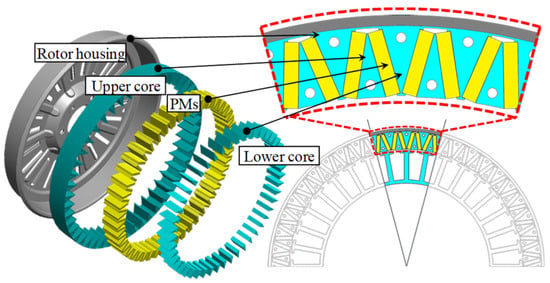
Figure 1.
Proposed V-shaped IPMSM without the magnetic leakage flux path.
The conventional model currently used for the target system is analyzed based on statistical methods. From this analysis, design directions to simultaneously improve the efficiency at the two main operating points are derived. As the efficiency at the high-torque-and-low-speed point is lower than that at the high-speed-and-low-torque point, priority is given to improving the low-speed efficiency.
Design variables are selected based on sensitivity analysis, and Gaussian process models (GPMs) are constructed using a Latin hypercube design (LHD). These models provide more accurate prediction performance than conventional response surface models (RSMs) [,]. A gradient-based optimization algorithm is applied to obtain the optimal design solution. Experimental validation is conducted to confirm both the structural feasibility and efficiency improvement of the proposed machine compared to the conventional SPMSM.
In this study, the primary design objectives are as follows: (1) to eliminate the magnetic leakage flux path in an external rotor IPMSM through a novel V-shaped rotor topology, (2) to improve the efficiency at two representative operating points: low-speed/high-torque and high-speed/low-torque points, (3) to enhance torque density without sacrificing structural robustness, and (4) to ensure manufacturability for home appliance applications. These objectives are addressed by combining statistical analysis, GPM-based optimization, and experimental validation.
2. Analysis of Conventional External SPMSM
Figure 2a shows the conventional SPMSM that is currently being used for the targeted home appliance. As the targeted system mainly operates at two points, the efficiency of the conventional model had to be improved at the two main operating points, high-torque-and-low-speed point A and low-torque-and-high-speed point B, as shown in Figure 2b. In this section, the conventional model is analyzed based on a statistical method. The motor characteristics such as the current and the loss are calculated using the d- and q-axis equivalent circuit method combined with FEA []. Contrary to the stator using laminated cores, the rotor housing of the conventional model consists of carbon steel, which is an unlaminated core. As the unlaminated carbon steel has a magnetic property, the PMs were directly attached to the rotor housing. Considering the costs, it was decided to use ferrite magnets and aluminum coils. Because the residual induction of ferrite PMs is low and the resistivity of aluminum coils is high, the efficiency of the conventional SPMSM is low at both points. Especially, the efficiency at point A is lower than that at point B. Accordingly, priority consideration is given to point A efficiency when deciding design directions for efficiency improvement.
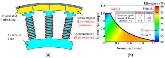
Figure 2.
Conventional SPMSM: (a) Configuration; (b) Efficiency map and characteristics curve.
2.1. Characteristics
The characteristics of the conventional SPMSM are analyzed according to the d- and q-axis equivalent circuit method using Equations (1)–(6):
where T is torque, Pn is the number of pole pairs, and Vo is induced voltage. Ψa is the linkage flux at no load. The d- and q-axis inductances Ld and Lq, respectively, and the iron loss Wiron were calculated using FEA. Io denotes the magnitude of the magnetizing current, and β denotes the current phase angle. Iod and Ioq are the d- and q-axis magnetizing currents, respectively, and Icd and Icq denote the d- and q-axis equivalent iron loss currents, respectively. By summing the magnetizing current and equivalent iron loss current, Id and Iq denote the d- and q-axis input currents, respectively. ωe and ωm denote the electrical and mechanical angular frequencies, respectively. Wohmic denotes the ohmic loss, Ra denotes the phase resistance, ρal is the resistivity of aluminum, lcoil is the length of the coil, and Acoil is the cross-sectional area of the coil.
The current at each operating point is determined by the circuit parameters. The d-axis current was maintained at zero for low-speed point A in accordance with the maximum-torque-per-ampere control method. For high-speed point B, the negative d-axis current was used to suppress the induced voltage according to the flux-weakening control method.
In this paper, two losses of the PMSM that much affected motor efficiency were considered: ohmic loss and iron loss. The ohmic and iron losses of the conventional SPMSM are shown in Figure 3. The ohmic loss of the PMSM is generated in the stator winding coils and determined by the resistance and input current. The resistance is related to the length and the cross-sectional area of the coils, as well as the resistivity of the coil material. The magnitude of the current is determined by the circuit parameters and operating point. As shown in Figure 3a, it is evident that the ohmic loss increases as the torque increases, since the output torque is proportional to the current. As a result, the ohmic loss is the largest at point A, and has a greater effect on point A efficiency than the iron loss. The other loss is the iron loss generated in the stator and rotor core. The magnitude and frequency of the magnetic flux density on the cores affect the amount of iron loss, which means that the iron loss is determined by the material properties and the rotating speed. As the rotating speed increases, the fundamental frequency of the SPMSM also increases, which leads to a significant rise in iron loss, as shown in Figure 3b.
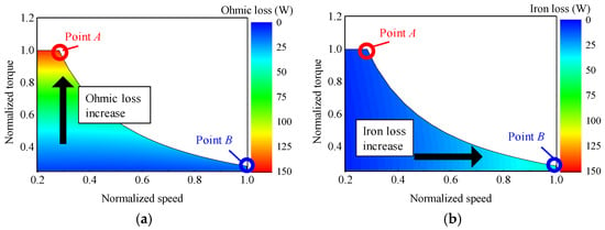
Figure 3.
Loss of conventional SPMSM: (a) Ohmic loss; (b) Iron loss.
In summary, the ohmic loss refers to the resistive power loss generated in the stator winding conductors due to the current flow, while the iron loss originates from hysteresis and eddy current phenomena occurring in the magnetic cores of the stator and rotor under alternating flux conditions. These definitions are consistently applied throughout the paper. As shown in Figure 3b, the iron loss is the largest at point B and has a greater effect on point B efficiency.
2.2. Main Effects and Design Directions for Parameters
To determine the design directions for improving the efficiency at both points A and B, the effects of the circuit parameters on each efficiency are statistically investigated []. The circuit parameters are selected from Equations (1)–(6): these are the linkage flux at no load, the resistance, the d-axis inductance, the q-axis inductance, and the iron loss. The three-level design is written based on the orthogonal array method, and the 18 design of experiments (DOE) samples are presented in Figure 4a.
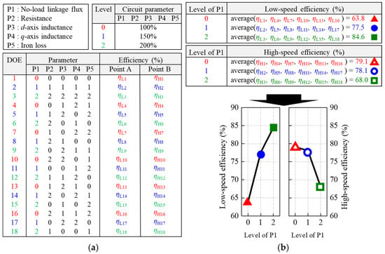
Figure 4.
Procedure of main effects analysis: (a) Design of experiment table for the circuit parameters; (b) Main effects plot.
Following the DOE table constructed using the orthogonal array method, the circuit parameters are varied across 18 samples, and the efficiencies at point A and B are calculated using the equivalent circuit combined with FEA. To analyze the influence of each parameter independently, main effects analysis is conducted. Each parameter has three levels (levels 0, 1, and 2), and the samples are grouped accordingly. Within each level group, the average efficiency is calculated. The difference in these averages across levels represents the “main effect” of that parameter on efficiency. Figure 4b shows this procedure using the no-load linkage flux (P1) as an example. The plot shows how the average efficiency changes with increasing parameter level, indicating the degree and direction of its influence. Through this process, the main effects of each parameter are analyzed considering variation in the other parameters [].
In Figure 5, the main effects of all five parameters are summarized. Parameters that increase efficiency are shown in red, while those that decrease efficiency are shown in blue. This analysis forms the basis for determining the design directions in the next step. Accordingly, a large no-load linkage flux and a small resistance are required for the improvement of the efficiency at point A. The remaining parameters are shown to have a small effect on point A efficiency. On the other hand, point B efficiency is significantly affected by most of the parameters.
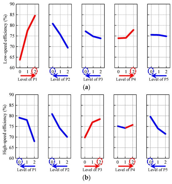
Figure 5.
Main effects plot of parameters: (a) Efficiency at point A; (b) Efficiency at point B.
As the point A efficiency is lower than the point B efficiency, point A efficiency improvement is considered a priority in this study. In the target application—a washing machine—point A corresponds to the washing mode, which operates under low-speed and high-torque conditions. Point B, on the other hand, corresponds to the spinning mode, which operates at high speed and low torque. Although the output power at both points is similar, the washing mode is used more frequently and for a longer duration. Consequently, the efficiency at point A has a greater impact on the total energy consumption, making it the primary target for improvement. Thus, the no-load linkage flux has to be increased to enhance the torque production at point A, where the motor operates under low-speed, high-torque conditions. However, increasing the no-load flux also raises the back electromotive force (BEMF), especially at high-speed operation (point B). To suppress this elevated BEMF and maintain proper control, a higher negative d-axis current is required through flux-weakening control. This additional current can lead to increased core saturation and iron loss, which degrade the efficiency at point B. Therefore, to minimize total loss at high speed, other parameters such as phase resistance and inductance must be reduced. By reducing the resistance and inductance, the induced voltage can be effectively limited. This trade-off ensures improved efficiency at both operating points.
To determine the design directions, the material cost is considered in addition to efficiency. This is because low cost is as important a requirement for a home appliance as motor efficiency. Table 1 presents the unit cost of the materials for PM machines []. For the conventional model, the ferrite magnets, aluminum coils, and S60 core were used. Considering the material costs, it is hard to change the PM and coil materials. Instead, changing the core material within similar grades is reasonable because the unit cost of the core is the lowest. Accordingly, the following design directions are determined in this section:

Table 1.
Unit cost of materials.
- 1.
- Increasing the air gap magnetic flux produced by PMs.
- 2.
- Decreasing coil turns.
- 3.
- Changing the core material from S60 to S18.
By increasing the air gap magnetic flux produced by the PMs, the no-load linkage flux can be enhanced even though the number of coil turns are reduced. The reduced number of coil turns results in an increase in coil diameter and a decrease in coil length, thereby reducing resistance overall. The reduced number of coil turns decreases not only the resistance but also the inductance. In addition to the large no-load linkage flux, the reduced inductance causes the high-speed efficiency to decrease. This is because the induced voltage of the PMSM has to be suppressed to operate at high-speed point B. Considering (2), the induced voltage can be suppressed using the negative d-axis current. When the no-load linkage flux is large and the inductance is small, the required magnitude of the d-axis current has to be large at high speeds. This causes the magnetic flux density in the cores to increase. However, the iron loss is unlikely to increase by changing the core material, although the magnetic flux density increases. As a result, it is possible to improve the efficiency at both points A and B.
3. Proposed V-Shaped IPMSM Without Magnetic Leakage Flux Path
In accordance with the design directions determined in the previous Section 2, a rotor structure for a large air gap magnetic flux produced by the PMs is introduced in this section. Among the many types of IPMSMs in existence, the spoke type is well known for its flux-concentrating effect. Therefore, many researchers have adopted the spoke type for internal rotor machines []. However, the spoke type is inappropriate to use for external rotors owing to the large magnetic leakage flux generation, as illustrated in Figure 6a. This is because the magnetic reluctance of the leakage flux path is small. Figure 6b shows that the air gap magnetic flux is limited no matter the length of the path in a restricted space for the rotor. To avoid a large amount of magnetic leakage flux, the existing V-shaped rotor topology is favorable for external rotating machines [,]. By arranging the PMs into a V-shape, the cross-sectional area of the magnetic leakage flux path is reduced compared to the spoke type. But still, the magnetic leakage flux in the existing V-shaped rotor is caused by the connection structure that exists for the structural stability of the rotor.
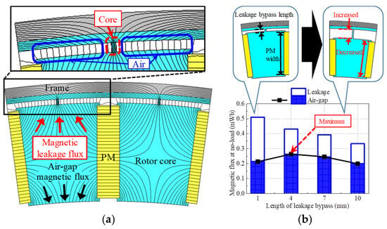
Figure 6.
Magnetic characteristics of external rotor spoke-type PMSM at no load: (a) Magnetic flux lines; (b) Magnetic flux according to leakage bypass length.
In this study, a V-shaped rotor without the magnetic leakage flux path is proposed, as shown in Figure 7a. By eliminating the connection structure, the rotor core is separated into the two parts: the upper core and the lower core. Even though the lower core is only adhesive to the PMs, its structural stability is sufficient. Eliminating the connection structure is feasible only in the external rotor because the centrifugal force of the lower core is applied outward. This means that the lower core is forced toward the PMs that support the lower core. Thus, scattering of the lower core scarcely occurs.
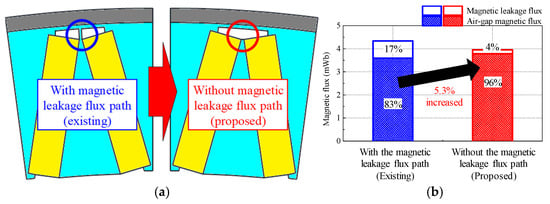
Figure 7.
Comparison of magnetic flux characteristics according to rotor type: (a) Configuration; (b) Magnetic flux by PMs.
The magnetic reluctance of the path between the upper and lower cores is large enough to reduce the magnetic leakage flux. Accordingly, the air gap magnetic flux produced by the PMs is increased, as shown in Figure 7b. In this comparison, the PM and core material, rotor size, and pole arc were the same. The stator core is assumed to be flat and has an infinite relative permeability property. In the existing V-shaped rotor that includes the connection structure in the rotor core, 17% of the magnetic leakage flux is generated. Whereas only 4% of the magnetic leakage flux is generated in the proposed V-shaped rotor without the magnetic leakage flux. A leakage flux of 39% occurs in the spoke type with the magnetic leakage flux path, and a leakage flux of 17% occurs in the V-shaped type with the magnetic leakage flux path. Therefore, the air gap magnetic flux produced by the PMs is the largest when applying the proposed V-shaped rotor.
4. Design Optimization Using Gaussian Process Model
In this section, a surrogate model-based design optimization is conducted to improve the efficiency at the two main operating points: high-torque-and-low-speed point A and low-torque-and-high-speed point B. As the surrogate model of efficiency, GPMs are employed. The LHD is adopted as the sampling method for constructing the GPMs. During the LHD-based sampling process, the current density is fixed to the same value used in the conventional model. The d- and q-axis equivalent circuit method combined with FEA is used for calculating the efficiency at each of the LHD sampling points. Figure 8 presents the design optimization process. First, sensitivity analysis of the efficiency at points A and B is conducted considering the different motor characteristics according to the operating points. From the sensitivity analysis results, the significant design variables are selected. Using the selected significant design variables, the GPMs of each efficiency are built. As the sampling technique for GPM construction, the LHD method is adopted. Then, a gradient–based optimization is conducted. As a result, the optimum design model of the proposed V-shaped IPMSM without the magnetic leakage flux path is determined in this section.
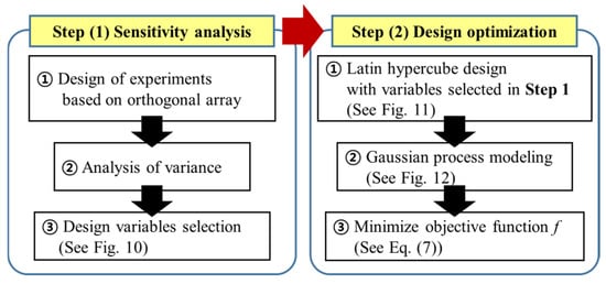
Figure 8.
Optimal design process.
4.1. Sensitivity Analysis
The computational costs required for design optimization are related to the number of design variables. To reduce the computational cost, the design variables that have statistically significant effects on point A and B efficiencies are selected in this section. The constant geometry dimensions and candidates for design variables are presented in Figure 9. Based on analysis on variance (ANOVA), the sensitivity of each efficiency is investigated considering the seven candidates. Based on the orthogonal array method, 36 DOE points were constructed. After calculating the probability value (p-value) of the seven candidate variables using ANOVA, those with p-values less than the significance level of 0.05 were considered to have statistically significant effects on efficiency [,]. For point A (low-speed operation), five variables were selected: pole angle, yoke thickness, slot opening, stator eccentricity, and rotor chamfer b. For point B (high-speed operation), six variables were significant: pole angle, yoke thickness, slot opening, stator eccentricity, and both rotor chamfers a and b. These parameters were chosen for the optimization process because they directly impact the magnetic circuit geometry and flux distribution. Their variation leads to notable changes in iron loss, flux-weakening performance, and output torque, which are key to achieving optimal efficiency across both operating conditions.
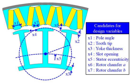
Figure 9.
Geometry dimension for proposed V-shaped IPMSM without leakage bypass.
Figure 10 presents the ANOVA results for each efficiency, showing the design variables that are significant for low- and high-speed efficiency. It is evident that pole angle, yoke thickness, slot opening, stator eccentricity, and rotor chamfer b are significant for low-speed efficiency. Similarly, six design variables are significant for high-speed efficiency: pole angle, yoke thickness, slot opening, stator eccentricity, and rotor chamfers a and b. The tooth tip has a negligible effect on the efficiency at both speeds; therefore, its initial value is used in the design optimization.
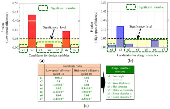
Figure 10.
Sensitivity analysis results: (a) Low-speed efficiency (point A); (b) High-speed efficiency (point B); (c) Selection of design variables.
4.2. Gaussian Process Model
Using the selected design variables, the GPMs for each efficiency are constructed in this section. A GPM is a proper model to replace an FEA simulation in which the random error is nonexistent and repeated experimentation is unnecessary []. The LHD is adopted as the sampling technique, which is well known as being suitable for GPMs []. As shown in Figure 11, the design points are well spread out across the entire design region. The respective efficiencies at the sampling points are calculated with FEA, and Figure 12 shows the constructed GPMs.
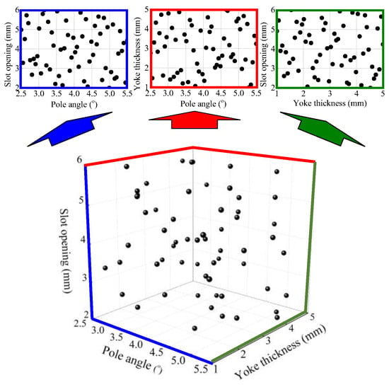
Figure 11.
Latin hypercube design points according to pole angle, yoke thickness, and slot opening.
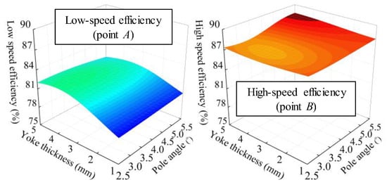
Figure 12.
Gaussian process models according to pole angle and yoke thickness.
Then, the accuracies of the constructed GPMs are evaluated based on the leave-one-out cross-validation method []. The normalized root mean square error (NRMSE) of the GPM is defined in Equation (7):
where x denotes the vector of design variables. Y(x) denotes the vector of the efficiency at points A and B. ns denotes the number of sampling points. xi denotes the input value at the ith sample point, and Y(xi) is the response at the ith sample point calculated in FEA. is the predicted response at the ith sample point from the GPM constructed using the sampling points without (xi, Y(xi)). The NRMSEs of the GPM for the point A and B efficiencies are calculated as 5.2%, and 0.8%, respectively. Thus, the GPMs are verified to be adequately accurate.
4.3. Design Optimization
Considering the efficiency at the two main operating points, the objective function is defined by Equation (8):
where F is the objective function, and b is the vector of the design variables. f1 and f2 denote the functions of the point A and point B efficiencies, respectively. w1 and w2 are the weighting factors of f1 and f2, respectively.
A flow chart of the optimization is shown in Figure 13. First, the design variables are initialized. With the constructed GPMs, the values of the efficiency at points A and B are predicted. Thus, the defined objective function is calculated. Then, a gradient of the objective function is calculated. Until the gradient value of the objective function is less than epsilon, the computation of the search direction, determination of the step size, and updating of the design variables are continued. If the gradient value converges, the optimization ends. As a result, the objective function is minimized and the optimum point is found, as shown in Figure 14. The optimized design variables are presented in Table 2.
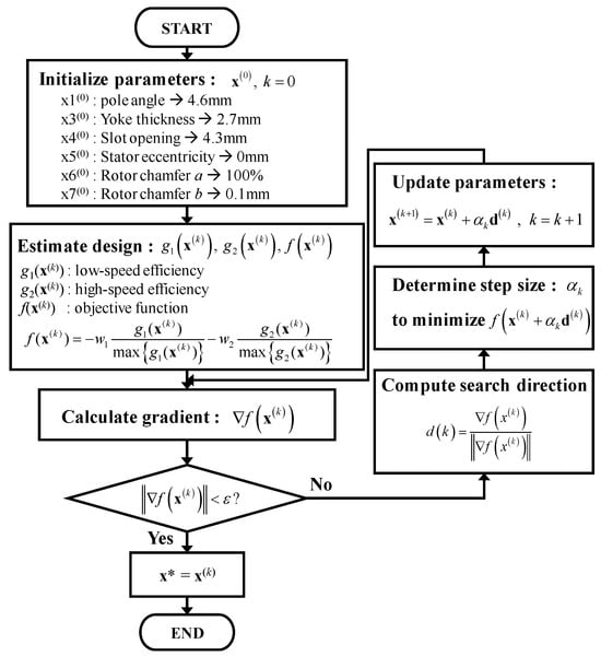
Figure 13.
Optimization process.

Figure 14.
Design optimization: (a) Pole angle and Yoke thickness; (b) slot opening and stator eccentricity; (c) Rotor chamfers a and b.

Table 2.
Design optimization results.
4.4. Simulation Results
Using FEA, the optimized V-shaped IPMSM without the magnetic leakage flux path is analyzed and compared with the experimental results. A prototype of the improved model was fabricated, as shown in Figure 15a. As proposed, the magnetic leakage flux path is nonexistent in the rotor. In Figure 15b, it is evident that the no-load BEMF predicted using FEA has an error of 0.5% with the experimental result, whereas the resistance has an error of 2.1%. These errors were calculated based on the test results as reference. As shown in Figure 15c, the efficiency at each operating point can be predicted through the simulation: 84.5% at low-speed point A and 86.5% at low-speed point B. Each predicted efficiency has an error less than 1%p compared with the test results. Therefore, the simulation results of the improved model are validated.
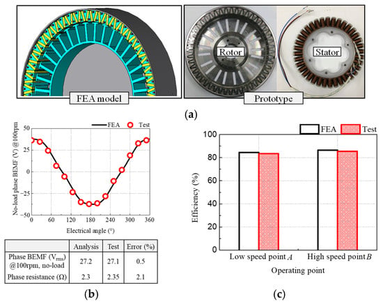
Figure 15.
Improved model: (a) FEA model and prototype; (b) No-load back-electromotive force and resistance; (c) Efficiency.
5. Experimental Verification
In this section, the optimized V-shaped IPMSM without the magnetic leakage flux path is termed the improved model. Then, the efficiencies of the improved model and the conventional model are experimentally tested and compared. Both models are optimized, respectively. The prototypes of both models are presented in Figure 16a. The set-ups for the no load and load tests are presented in Figure 16b. For the no load test, a DC motor is used to rotate the test motor. The test motor is connected to a Y-connected resistor, which has a very large resistance. While the test motor is rotated, the voltage of the Y-connected resistor is measured using an oscilloscope. The measured voltage represents the BEMF. For the load test, both the conventional and proposed models are evaluated under the same inverter-fed conditions to ensure a fair comparison. The torque, speed, and input power are measured, and the efficiency at each operating point are calculated according to the following equation:
where η is the efficiency, T is the torque, ω is the rotating speed, and Pin is the input power. As shown in Figure 17a, the increased flux and reduced resistance of the improved model, compared with the conventional model, are validated by measuring the BEMF and phase resistance. The BEMF of the proposed model is enhanced by 27%, and the resistance is reduced by 47%. Figure 17b illustrates the degree of improvement in the efficiency of the proposed model. By conducting the design optimization for the efficiency at low- and high-speed operating points where the motor characteristics are different, the overall efficiency of the proposed model is increased throughout the torque and speed. Compared with the conventional model, the efficiency of the proposed model is improved by 14%p at low-speed point A, 1.4%p at high-speed point B, and 10.2%p on average.
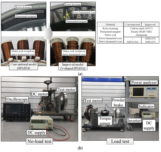
Figure 16.
Prototype and test set-up: (a) Prototypes of conventional and improved models; (b) No load and load test set-ups.
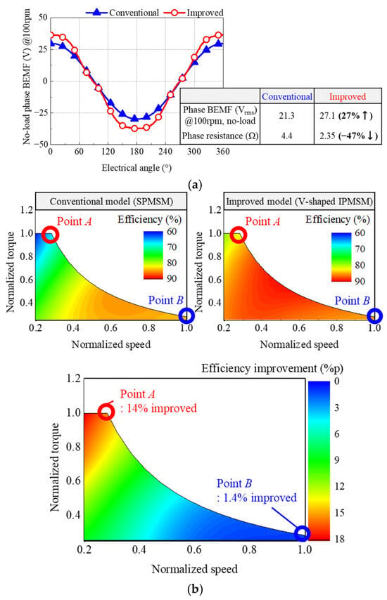
Figure 17.
Experimental results of conventional and improved models. (a) No-load back-electromotive force and resistance; (b) Efficiency.
The efficiency improvement mechanisms differ across the two operating points. At low speed, the increased back-EMF allows the motor to deliver the required torque with lower current. Combined with the reduced phase resistance, this leads to significantly lower ohmic loss and higher efficiency. At high speed, although the increased no-load flux raises the risk of higher iron loss and d-axis current, these effects are mitigated by using a low-loss core material and reducing the resistance. As a result, both iron and ohmic losses decrease, resulting in improved efficiency at high speed as well.
6. Conclusions
This paper presents a high-efficiency design for an external rotor machine for a home appliance having two main operating points. By analyzing the conventional model using the statistical method, the design directions were determined. According to the design directions, a V-shaped IPMSM without the magnetic leakage flux path was proposed. Then, design optimization was conducted to decide the optimum design model of the proposed V-shaped IPMSM without the magnetic leakage flux path. By fabricating and testing prototypes of both the conventional and the improved models, the validity of the improved model was confirmed. Compared with the conventional model, the average efficiency of the improved model was improved by 10.2%p. At high-torque-and-the-low-speed point A, the efficiency improved by 14%p, and at low-torque-and-the-high-speed point B, the efficiency improved by 1.4%p. Moreover, the torque density of the proposed V-shaped PMSM without leakage bypass was increased compared with the conventional PMSM by 26.6%, from 12.4 kNm/m3 to 15.7 kNm/m3. As the other important requirement is low cost, a high-efficiency design that considers the cost is required in future work.
Author Contributions
Conceptualization, S.-G.L. and M.-R.P.; methodology, S.-G.L.; software, K.-S.C.; validation, J.-H.K.; resources, K.-S.C.; data curation, J.-H.K.; writing—original draft preparation, K.-S.C. and J.-H.K.; writing—review and editing, M.-R.P.; visualization, S.-G.L.; supervision, M.-R.P.; project administration, M.-R.P.; funding acquisition M.-R.P. All authors have read and agreed to the published version of the manuscript.
Funding
This work was supported by the Soonchunhyang University Research Fund.
Data Availability Statement
Data are contained within the article.
Conflicts of Interest
Author Soo-Gyung Lee was employed by the company Global R&D Center. The remaining authors declare that the research was conducted in the absence of any commercial or financial relationships that could be construed as a potential conflict of interest. The Global R&D Center had no role in the design of the study; in the collection, analyses, or interpretation of data; in the writing of the manuscript, or in the decision to publish the results.
References
- Shen, Y.; Zhu, Z.Q. Analytical prediction of optimal split ratio for fractional-slot external rotor PM brushless machines. IEEE Trans. Magn. 2011, 47, 4187–4190. [Google Scholar] [CrossRef]
- Kong, Y.; Lin, M.; Guo, R.; Li, N.; Xu, D. Design and optimization of an outer-rotor permanent magnet synchronous machine with an amorphous stator core. IEEE Trans. Appl. Supercond. 2018, 28, 1–5. [Google Scholar] [CrossRef]
- Lee, T.Y.; Ki, M.; Seo, M.; Kim, Y.J.; Jung, S.Y. Motor design and characteristics comparison of outer-rotor-type BLDC motor and BLAC motor based on numerical analysis. IEEE Trans. Appl. Supercond. 2016, 26, 1–6. [Google Scholar] [CrossRef]
- Aghazedeh, H.; Afjei, E.; Siadatan, A. Sizing and detailed design procedure of external rotor synchronous reluctance machine. IET Electr. Power Appl. 2019, 13, 1105–1113. [Google Scholar] [CrossRef]
- Sone, K.; Takemoto, M.; Ogasawara, S.; Takezaki, K.; Akiyama, H. A ferrite PM in-wheel motor without rare earth materials for electric city commuters. IEEE Trans. Magn. 2012, 48, 2961–2964. [Google Scholar] [CrossRef]
- Bonthu, S.S.R.; Arafat, A.; Choi, S. Comparisons of rare-earth and rare-earth-free external rotor permanent magnet assisted synchronous reluctance motors. IEEE Trans. Ind. Electron. 2017, 64, 9729–9738. [Google Scholar] [CrossRef]
- Xue, X.D.; Cheng, K.W.E.; Ng, T.W.; Cheung, N.C. Multi-objective optimization design of in-wheel switched reluctance motors in electric vehicles. IEEE Trans. Ind. Electron. 2010, 57, 2980–2987. [Google Scholar] [CrossRef]
- Beniakar, M.E.; Kakosimos, P.E.; Kladas, A.G. Strength pareto evolutionary optimization of an in-wheel PM motor with unequal teeth for electric traction. IEEE Trans. Magn. 2015, 51, 1–4. [Google Scholar] [CrossRef]
- Chung, S.U.; Moon, S.H.; Kim, D.J.; Kim, J.M. Development of a 20-pole–24-slot SPMSM with consequent pole rotor for in-wheel direct drive. IEEE Trans. Ind. Electron. 2016, 63, 302–309. [Google Scholar] [CrossRef]
- Öksüztepe, E. In-wheel switched reluctance motor design for electric vehicles by using a Pareto-based multiobjective differential evolution algorithm. IEEE Trans. Veh. Technol. 2017, 66, 4706–4715. [Google Scholar] [CrossRef]
- Wrobel, R.; Mellor, P.H. Design considerations of a direct drive brushless machine with concentrated windings. IEEE Trans. Energy Convers. 2008, 23, 1–8. [Google Scholar] [CrossRef]
- Chen, J.; Nayar, C.V.; Xu, L. Design and finite-element analysis of an outer-rotor permanent-magnet generator for directly coupled wind turbines. IEEE Trans. Magn. 2000, 36, 3802–3809. [Google Scholar] [CrossRef]
- Chen, H.; Gu, J.J. Switched reluctance motor drive with external rotor for fan in air conditioner. IEEE/ASME Trans. Mechatron. 2012, 18, 1448–1458. [Google Scholar] [CrossRef]
- Lim, M.S.; Kim, J.H.; Hong, J.P. Experimental characterization of the slinky-laminated core and iron loss analysis of electrical machine. IEEE Trans. Magn. 2015, 51, 1–4. [Google Scholar] [CrossRef]
- Ahn, H.J.; Lee, D.M. A new bumpless rotor-flux position estimation scheme for vector-controlled washing machine. IEEE Trans. Ind. Electron. 2016, 12, 466–473. [Google Scholar] [CrossRef]
- Raj, M.A.; Kavitha, A. Effect of rotor geometry on peak and average torque of external-rotor synchronous reluctance motor in comparison with switched reluctance motor for low-speed direct-drive domestic application. IEEE Trans. Magn. 2017, 53, 1–8. [Google Scholar] [CrossRef]
- Li, D.; Qu, R.; Li, J.; Xu, W. Consequent-pole toroidal-winding outer-rotor Vernier permanent-magnet machines. IEEE Trans. Ind. Appl. 2015, 51, 4470–4481. [Google Scholar] [CrossRef]
- Li, L.; Zhang, J.; Zhang, C.; Yu, J. Research on electromagnetic and thermal issue of high-efficiency and high-power-density outer-rotor motor. IEEE Trans. Appl. Supercond. 2016, 26, 1–5. [Google Scholar] [CrossRef]
- Ma, C.; Chen, C.; Li, Q.; Gao, H.; Kang, Q.; Fang, J.; Cui, H.; Teng, K.; Lv, X. Analytical calculation of no-load magnetic field of external rotor permanent magnet brushless direct current motor used as in-wheel motor of electric vehicle. IEEE Trans. Magn. 2018, 54, 1–6. [Google Scholar] [CrossRef]
- Moayed-Jahromi, H.; Rahideh, A.; Mardaneh, M. 2-D analytical model for external rotor brushless PM machines. IEEE Trans. Energy Convers. 2016, 31, 1100–1109. [Google Scholar] [CrossRef]
- Boughrara, K.; Ibtiouen, R.; Zarko, D.; Touhami, O.; Rezzoug, A. Magnetic field analysis of external rotor permanent-magnet synchronous motors using conformal mapping. IEEE Trans. Magn. 2010, 46, 3684–3693. [Google Scholar] [CrossRef]
- Zuo, S.; Lin, F.; Wu, X. Noise analysis, calculation, and reduction of external rotor permanent-magnet synchronous motor. IEEE Trans. Ind. Electron. 2015, 62, 6204–6212. [Google Scholar] [CrossRef]
- Lin, F.; Zuo, S.; Deng, W.; Wu, S. Modeling and analysis of acoustic noise in external rotor in-wheel motor considering Doppler effect. IEEE Trans. Ind. Electron. 2018, 65, 4524–4533. [Google Scholar] [CrossRef]
- Chu, W.; Zhu, Z.; Shen, Y. Analytical optimisation of external rotor permanent magnet machines. IET Electr. Syst. Transp. 2013, 3, 41–49. [Google Scholar] [CrossRef]
- Kim, K.C.; Lim, S.B.; Koo, D.H.; Lee, J. The shape design of permanent magnet for permanent magnet synchronous motor considering partial demagnetization. IEEE Trans. Magn. 2006, 42, 3485–3487. [Google Scholar] [CrossRef]
- Yoo, J.H.; Park, C.S.; Jung, T.U. Permanent magnet structure optimization for cogging torque reduction of outer rotor type radial flux permanent magnet generator. In Proceedings of the 2017 IEEE International Electric Machines and Drives Conference, Miami, FL, USA, 21–24 May 2017. [Google Scholar]
- Wu, S.; Song, L.; Cui, S. Study on improving the performance of permanent magnet wheel motor for the electric vehicle application. IEEE Trans. Magn. 2007, 43, 438–442. [Google Scholar] [CrossRef]
- Ma, C.; Cui, H.; Zheng, P.; Zhang, Y.; Gao, H. Influence of static eccentricity on unbalanced magnetic force of external rotor permanent magnet brushless direct current motor used as in-wheel motor. IET Electr. Power Syst. 2019, 13, 538–550. [Google Scholar] [CrossRef]
- Ifedi, C.J.; Mecrow, B.C.; Brockway, S.T.M.; Boast, G.S.; Atkinson, G.J.; Kostic-Perovic, D. Fault-tolerant in-wheel motor topologies for high-performance electric vehicles. IEEE Trans. Ind. Appl. 2013, 49, 1249–1257. [Google Scholar] [CrossRef]
- Ishii, S.; Hasegawa, Y.; Nakamura, K.; Ichinokura, O. Characteristics of novel flux barrier type outer rotor IPM motor with rare-earth and ferrite magnets. In Proceedings of the 2012 International Conference on Renewable Energy Research and Applications, Nagasaki, Japan, 11–14 November 2012. [Google Scholar]
- Yu, D.; Huang, X.; Zhang, X.; Zhang, J.; Lu, Q.; Fang, Y. Optimal design of outer rotor interior permanent magnet synchronous machine with hybrid permanent magnet. IEEE Trans. Appl. Supercond. 2019, 29, 1–5. [Google Scholar] [CrossRef]
- Yang, Y.; Rahman, M.M.; Lambert, T.; Bilgin, B.; Emadi, A. Development of an external rotor V-shape permanent magnet machine for E-bike application. IEEE Trans. Energy Convers. 2018, 33, 1650–1658. [Google Scholar] [CrossRef]
- Chen, Q.; Liu, G.; Zhao, W.; Sun, L.; Shao, M.; Liu, Z. Design and comparison of two fault-tolerant interior-permanent-magnet motors. IEEE Trans. Ind. Electron. 2014, 61, 6615–6623. [Google Scholar] [CrossRef]
- Lee, S.G.; Park, M.R.; Cha, K.S.; Kim, J.H.; Hong, J.P. Design of the high efficiency IPMSM considering the operating point with different characteristic. In Proceedings of the 2019 IEEE International Electric Machines and Drives Conference, San Diego, CA, USA, 12–15 May 2019. [Google Scholar]
- Bangura, J.F. Design of high-power density and relatively high-efficiency flux-switching motor. IEEE Trans. Energy Convers. 2006, 21, 416–425. [Google Scholar] [CrossRef]
- Jones, B.; Johnson, R.T. Design and analysis for the Gaussian process model. Qual. Reliab. Eng. Int. 2009, 25, 515–524. [Google Scholar] [CrossRef]
- Zhang, X. Comparison of response surface method and Kriging method for approximation modeling. In Proceedings of the 2017 IEEE 2nd International Conference on Power and Renewable Energy, Chengdu, China, 20–23 September 2017. [Google Scholar]
- Park, M.R.; Kim, H.J.; Choi, Y.Y.; Hong, J.P.; Lee, J.J. Characteristics of IPMSM according to rotor design considering nonlinearity of permanent magnet. IEEE Trans. Magn. 2016, 52, 1–4. [Google Scholar] [CrossRef]
- Roy, R.K. Design of Experiments Using the Taguchi Approach: 16 Steps to Product and Process Improvement; John Wiley & Sons: New York, NY, USA, 2001. [Google Scholar]
- Montgomery, D.C. Design and Analysis of Experiments, 9th ed.; John Wiley & Sons: New York, NY, USA, 2017. [Google Scholar]
- Johnson, M.; Gardner, M.C.; Toliyat, H.A. Design comparison of NdFeB and ferrite radial flux surface permanent magnet coaxial magnetic gears. IEEE Trans. Ind. Appl. 2018, 54, 1254–1263. [Google Scholar] [CrossRef]
- Kim, H.J.; Kim, D.Y.; Hong, J.P. Structure of concentrated-flux-type interior permanent-magnet synchronous motors using ferrite permanent magnets. IEEE Trans. Magn. 2014, 50, 1–4. [Google Scholar] [CrossRef]
- Queipo, N.V.; Haftka, R.T.; Shyy, W.; Goel, T.; Vaidyanathan, R.; Tucker, P.K. Surrogate-based analysis and optimization. Prog. Aerosp. Sci. 2005, 41, 1–43. [Google Scholar] [CrossRef]
Disclaimer/Publisher’s Note: The statements, opinions and data contained in all publications are solely those of the individual author(s) and contributor(s) and not of MDPI and/or the editor(s). MDPI and/or the editor(s) disclaim responsibility for any injury to people or property resulting from any ideas, methods, instructions or products referred to in the content. |
© 2025 by the authors. Licensee MDPI, Basel, Switzerland. This article is an open access article distributed under the terms and conditions of the Creative Commons Attribution (CC BY) license (https://creativecommons.org/licenses/by/4.0/).