Abstract
This paper investigates the nonlinear dynamic deflection, natural frequency, and wave propagation in functionally graded (FG) porous piezoelectric microscale tubes under periodic load, hygrothermal conditions, and an external electric field. The piezoelectric material used to make the smart microtubes has pores that may be smoothly changed or uniformly distributed over the tube wall. Here, three types of porosity distribution are taken into consideration. The nonlinear motion equations are constructed using a novel shear deformation beam theory and the modified couple stress theory (MCST). The nonlinear motion equations are solved using the fourth-order Runge–Kutta technique and the Galerkin approach. The effects of various geometric parameters, porosity distribution type, porosity factor, periodic load amplitude and frequency, material length scale parameter, moisture, and temperature on the nonlinear dynamic deflection, natural frequency, and wave frequency of FG porous piezoelectric microtubes are explored through a number of parametric investigations.
    Keywords:
                                                                    nonlinear dynamic deflection;                    piezoelectric;                    porous microtubes;                    periodic load;                    hygrothermal environments        MSC:
                74H45; 74H15; 74J05
            1. Introduction
Piezoelectric materials (PEMs) are currently attracting significant interest in industrial devices, sensors and actuators, medicinal products, military applications, and so on []. PEMs are often constructed in single-layer, bilayer, or multilayer patterns. Furthermore, several researchers have extended the concept of functionally graded materials (FGMs) [,] to improve the properties of PEMs. The material properties (MPs) are smoothly graded in one or more directions according to the FGM principle, preventing delamination and resisting undesirable wear and fractures. The capacity of PEMs to transform mechanical energy into electrical energy and vice versa distinguishes them from other materials. In this regard, when the deformed PEMs create electric charges or are exposed to an electric field, the mechanical deformations occur in these structures []. As a result, the sensors react to the oscillations by producing an electrical voltage. Before the voltage is supplied to the actuator, it is processed and amplified by a feedback gain. The actuator will create a control force due to the reverse piezoelectric effect []. As a result of their capacity to suppress active vibrations and regulate form, PEMs are extensively employed in the production of smart composites and systems. Therefore, various studies have been published in the literature to study such materials. The higher-order shear deformation theory (HSDT) was used by Fakhari et al. [] to show the nonlinear vibrational response of FG rectangular plates coupled with PEM sheets exposed to heat stresses. Kulikov and Plotnikova [] developed an accurate three-dimensional approximation for piezoelectric-laminated plates. They also investigated how FG piezoelectric-laminated panels behaved when exposed to mechanical and electrical stresses []. Mirzavand et al. [] presented the post-buckling behavior of cylinders with piezoelectric actuators subjected to applied actuator voltage and thermal load. In addition, Moradi-Dastjerdi and Behdinan [] examined the free vibration behavior of porous FG carbon nanotubes-reinforced sandwich plates with piezoelectric face sheets. Moreover, Abazid and Sobhy [] provided an illustration of the electrothermal bending of FG PEM microscale plates lying on an elastic foundation. Furthermore, there are several recent publications about the behaviors of PEMs and composite structures integrated with piezoelectric sheets, such as those of Al Mukahal et al. [], Sobhy and Radwan [], Liu and Wensai [], and Alsebai et al. [].
Because of their exceptional versatility, which includes low specific weight, good marine buoyancy, reduced electrical and thermal conductivity, acoustic damping, enhanced recyclability, high energy dissipation rate, and good machinability, porous structures [,,,] are garnering a lot of attention as sophisticated building materials in the fields of civil engineering, automotive engineering, and aerospace engineering. Metal foams are porous materials that are lightweight and have cellular structures made of solid metal, which have a significant volume fraction of gas-entrapped porosities. A considerable difference in solidification temperatures between the component materials causes micro gaps and holes in the sandwich plate []. The inclusion of porosity decreases structural rigidity with increasing bulk. Furthermore, optimizing the material distribution and porosity distribution of these structures throughout their thickness might increase structural strength or minimize the stress concentration phenomena on the surfaces. As a result, it is crucial to take into account how pores affect the static and dynamic behavior of FGM plates. Reddy’s higher-order shear deformation plate theory has been employed by Cong et al. [] to illustrate the buckling and post-buckling behavior of FGM plates with porosities when they are supported by elastic foundations and are subject to mechanical, thermal, and thermomechanical loads. Sobhy [] discussed the thermal buckling of sandwich microscale plates and beams, including internal pores. Furthermore, Amir et al. [] have demonstrated the natural frequency of FG-carbon-nanotube-strengthened annular microscale plates with pores. The mechanical buckling and bending response of a composite sandwich beam with a porous core that is exposed to a heated environment were studied by Safaei et al. [].
The above literature review shows that the dynamical response of the FG porous piezoelectric cylindrical microtubes has not been studied. Motivated by this shortcoming and to fill this gap, the current paper aims to investigate the hygrothermal effects on the nonlinear forced vibration and waves, as well as the natural frequency of FG porous piezoelectric cylindrical microtubes embedded in an elastic medium. To lessen the effects of the temperature and moisture, various forms of porosity are taken into account in the current composed microtubes. The MCST is applied in order to account for the size impact. The virtual work concept and von Karman’s strain–displacement relation are used to establish the nonlinear motion equations. The equations of motion are solved using the Runge–Kutta technique and the Galerkin approach. The generated results are examined through some comparisons. Furthermore, impacts of the length-to-depth ratio, porosity coefficient, porosity distribution type, moisture, material length scale parameter, and temperature on the proposed microtubes are discussed.
2. Problem Formulation
Figure 1a shows an FG porous microtube of length a and wall thickness h. The microtube is composed of PEMs with internal porosities that may be evenly or unevenly dispersed. According to the MCST [] and PEMs theory [], the change in the strain energy  involves the strain tensor , curvature tensor , and electric field , as follows:


      where , , and  are, respectively, the stress tensor, the couple stress tensor, and the electric displacements [] that can be given as


      where C stands for the moisture,  is the temperature, G is the shear modulus, and  is the material length scale parameter. However,  represent the elastic coefficients,  and  are, respectively, moisture and thermal moduli,  are the electric field components,  denote the piezoelectric coefficients,  are the dielectric coefficients, and  and  represent, respectively, the hygroelectric and pyroelectric coefficients that can be expressed as [,]


    Figure 1.
      (a) Configuration of a porous piezoelectric microtube and (b) porosity distribution types.
  
Based on von Karman’s nonlinearity relations, the strain components  are given as [,]


      where u, v, and w represent the displacements. The curvature tensor  is represented in the Cartesian coordinate as [,]


      where  is the rotation component that relates to the displacements as []


      To describe the displacements of the micro/nanotubes, several beam theories such as those of Euler–Bernoulli and Timoshenko, and higher-order theories have been used [,,,,]. For the present problem, the displacement field is given via an HSDT as follows:


      where  is given as follows []:


      By using Equations (6) and (9), the nonzero strain components can be given as


      In addition, based on the displacement field (9), the nonzero rotation and curvatures can be deduced as


2.1. Electric Field
The electric field e as a function of the electric potential  is expressed by []


        where  is defined as []


        where  and  are the external electric voltage and spatial variation, respectively.
2.2. Hygrothermal Field
The current research takes into account different temperature and moisture distributions across the thickness. For a precise description of the temperature and moisture impacts, they are taken as follows []:


        where  and  are the temperature and moisture at the bottom surface (top surface), and  refers to the hygrothermal exponent.
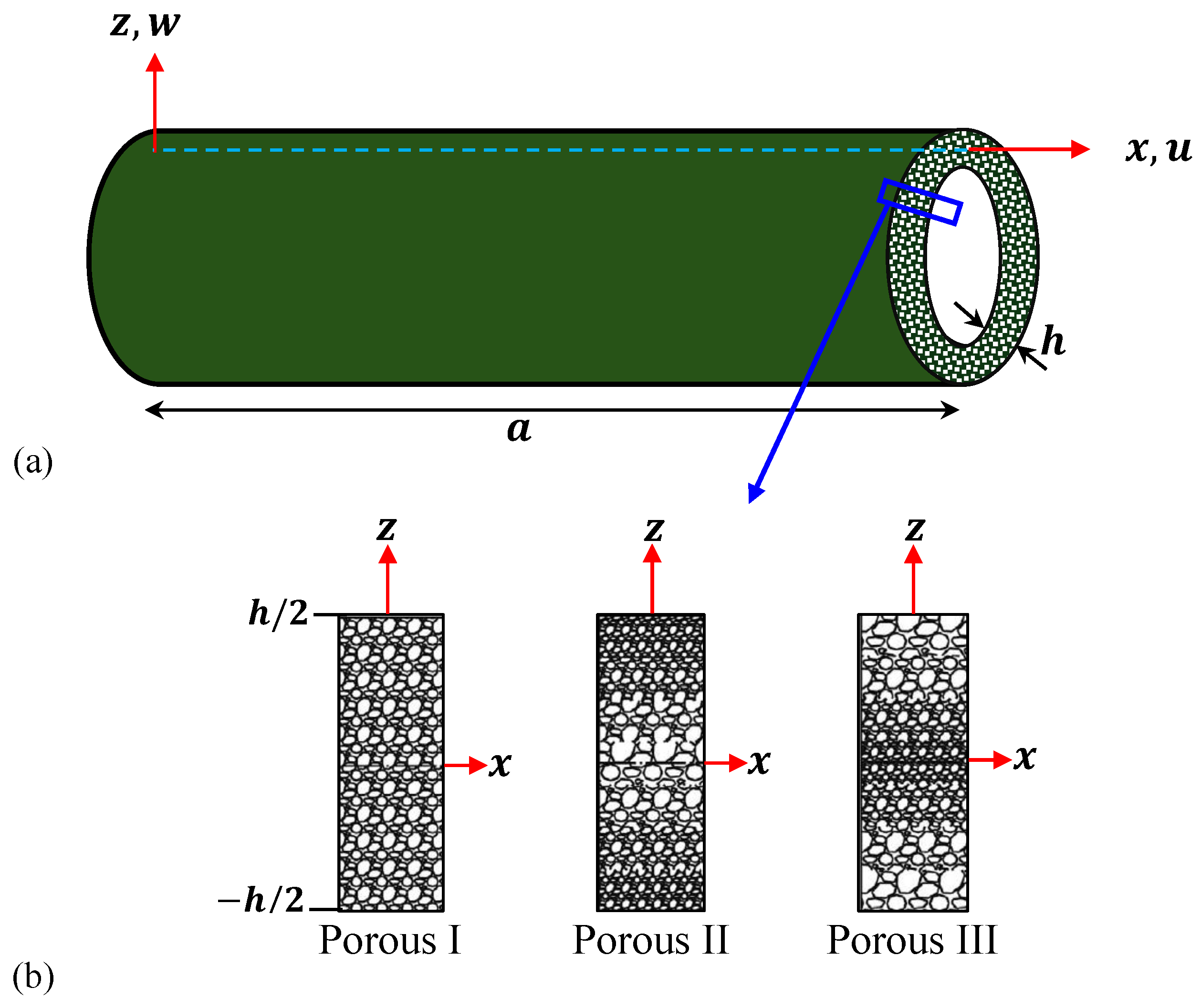
2.3. Porosity Distribution Types
2.3.1. Porous I
In this type (see Figure 1b), the mechanical, thermal, and piezoelectric properties R as well as the mass density  are evenly varied across the thickness of the microtube, as follows [,]:


          where  is the porosity coefficient, wherein ; the subscript m denotes the maximum value of the MPs; and the parameter  is defined as [,]


2.3.2. Porous II
The largest values of the MPs for Porous II will occur at the outer and inner surfaces of the tube, while the lowest values of the MPs will occur at the middle of the tube wall (see Figure 1b); therefore, one can write [,]


2.3.3. Porous III
In this case, the lowest values of the MPs for Porous III will occur at the outer and inner surfaces of the tube, while the largest values of the MPs will occur at the middle of the tube wall (see Figure 1b); thus, we have [,]


          Note that Poisson’s ratio of the FG porous microtube is defined for all cases as []


2.4. Equations of Motion
The motion equations can be derived by employing Hamilton’s principle that can be defined as


        where the change in the work conducted by the periodic load  and the kinetic energy  are defined below. By incorporating Equations (11), (12), and (15) into Equation (1), the change in the strain energy  can be expressed as


        where


        The change in the kinetic energy  is given as


        where  is the displacement vector. Inserting Equation (9) into Equation (26) shows that


        where


        The change in the work conducted by the periodic load  is given as


        where  is the periodic load applied to the microtube that can be defined as


        in which  stands for the amplitude and  is the frequency of the periodic load.
Inserting Equations (24), (27), and (29) into Equation (23) and applying the integration by parts lead to the equations of motion as follows:


        Inserting Equations (3), (4), and (16) into Equation (25) leads to


        where


        By substituting Equation (32) into Equation (31) and by simplifying the resulting equations, we can obtain the equations of motion:


3. Solution Procedure
3.1. Nonlinear Dynamic Solution
We will solve our problem under the simply supported conditions that can be expressed as follows:


        It is assumed that the approximate solutions for w, , and  that meet the boundary conditions (35) are


        where .
By inserting Equation (36) into Equation (34) and then employing the Galerkin procedure, one obtains the governing equations as


        where


        in which


        By eliminating the function  from Equation (37), one obtains


        By solving Equation (40) using the Runge–Kutta method, the displacements can be obtained based on the following initial condition: , where  and  are constants that will be given later.
3.2. Linear Dynamic Solution
Based on the virtual displacement concept [,,], the motion equations of the microtube are deduced at a neighboring stable state. Accordingly, the total displacements and electric potential of a neighboring state are given as:


        where  are the equilibrium state displacements, while  represent the virtual displacements of the dynamical state.
3.2.1. Frequency Solution
It is assumed that the approximate solutions for , , and  that meet the boundary conditions (35) are


          where ,  stands for the eigenfrequency; , , and  are unknown coefficients.
3.2.2. Wave Propagation Solution
The equations of motion (42) are solved analytically to obtain the wave frequency and phase velocity of the waves propagating in the x direction of the microtube. For this purpose, the displacement components are assumed as []


          where , , and  are the wave amplitude; k is the wave number of the waves.
4. Numerical Results and Discussion
The numerical results for the effects of the material length scale parameter, length-to-depth ratio, porosity coefficient, porosity distribution type, moisture, and temperature on the nonlinear deflection, natural frequency, and wave frequency of FG porous piezoelectric microtubes are presented in this section. For this purpose, the dimensionless quantities are defined by


      The material properties are given as follows:  GPa,  GPa,  GPa,  GPa,  GPa,  GPa,  C/m2,  C/m2,  C/m2,  C/Vm,  C/Vm,  Pa K,  Pa K,  GPa wt%H2O,  GPa wt%H2O,  C/m2K,  C/m2wt%H2O,  g/cm3.
In addition, the following data are used (unless otherwise stated):  m,  K,  V, ,  K, %,  = 1 kPa,  = 200 1/s, , .
4.1. Verification
To verify the accuracy of the current formulations, the first mode of the present natural frequency  of a homogeneous microbeam is compared with that obtained by Reddy [] for different values of the material length scale parameter  as shown in Table 1. Reddy [] depicted the frequency based on both the classical beam theory (CBT) and the first-order beam theory (FBT), while the present results are obtained based on a refined higher-order beam theory. Therefore, a slight deviation between the present frequency and that obtained by Reddy [] is noted.
       
    
    Table 1.
    Comparison of the natural frequency  of a simply supported homogeneous microbeam ( GPa, ,  g/cm3).
  
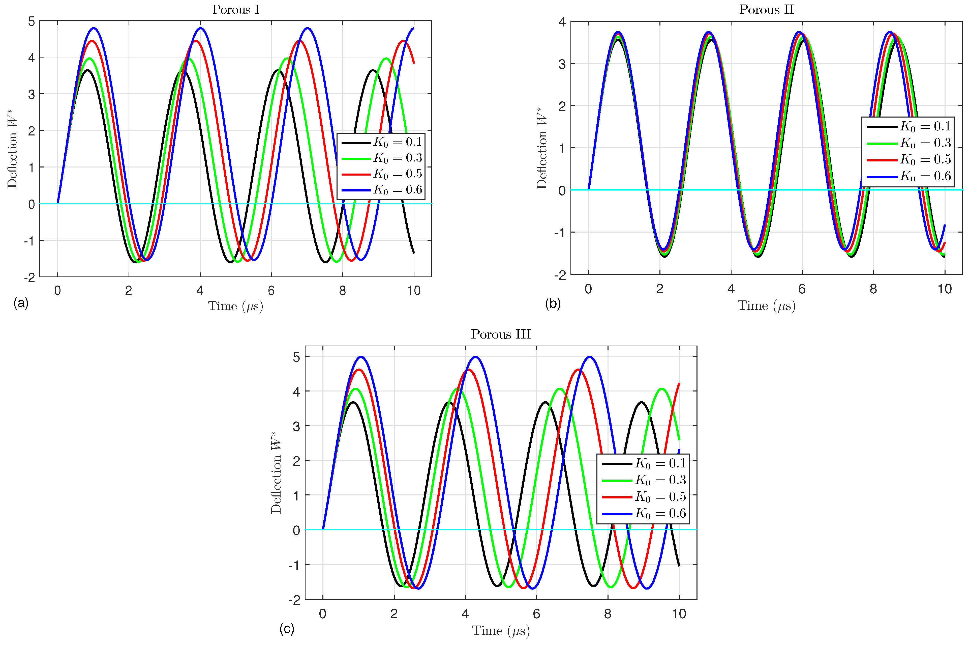
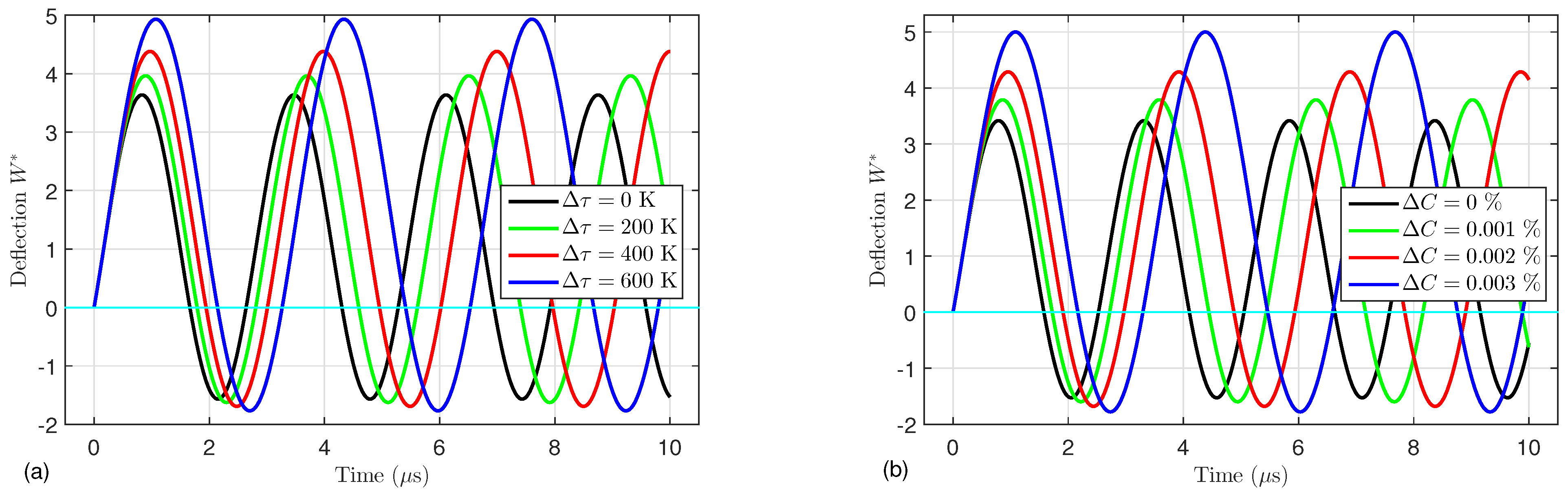
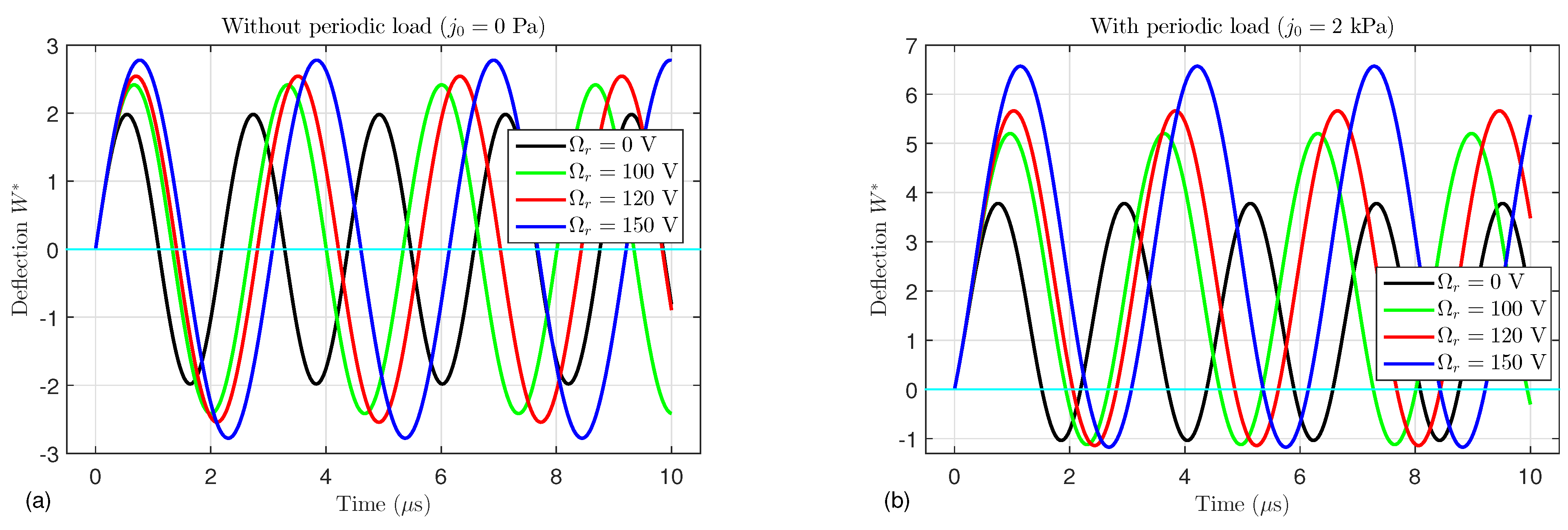
4.2. Nonlinear Dynamic Results
For three different porosity distributions (Porous I, II, and III), the effects of the porosity coefficient  on the nonlinear central deflection  of the FG porous piezoelectric microtubes are illustrated in Figure 2a, Figure 2b, and Figure 2c, respectively. It is evident that the lengths of the deflection waves of the Porous I and Porous III types increase with increasing porosity factor, whereas for the Porous II type, the wave length decreases as  increases. Because the increase in the porosities weakens the strength of the microtube, the amplitude of the deflection increases with increasing porosity coefficient. It can also be seen that the effect of the porosity factor on types I and III is more pronounced than on type II, because the porosities in the first and third types are more than those in the second one.
      
    
    Figure 2.
      Dimensionless deflection  versus the time for different values of the porosity coefficient  and different porosity distribution types: (a) type I, (b) type II, and (c) type III.
  
Figure 3 shows the nonlinear dynamic deflection  under the effects of the temperature change  and moisture change . Since the elevated temperature and moisture have a negative effect on the structures, a noticeable increment in the deflection occurs with increasing temperature and moisture.
      
    
    Figure 3.
      Effects of the (a) temperature change  and (b) moisture change  on the dynamic deflection  of an FG porous microtube ().
  
The effects of the external electric voltage  on the time-dependent deflection  of the FG porous microtube without periodic load () or with periodic load ( kPa) are illustrated in Figure 4. It is evident that, in the absence of the periodic load, the governing equations become a homogeneous system that gives symmetrical waves about the axis . On the other hand, the waves have been displaced upwards by applying the periodic load. It is noticed that by increasing the external electric voltage, the displacement increases.
      
    
    Figure 4.
      Effects of the external electric voltage  and time on the dynamic deflection  of an FG porous microtube (a) without a periodic load  Pa and (b) under a periodic load  kPa.
  
Figure 5 shows the nonlinear dynamic deflection  of the FG porous microtube for different values of the load amplitude . It can be seen that increasing the amplitude of the periodic load leads to an increment in the deflection.
      
    
    Figure 5.
      Effects of the amplitude  of the periodic load on the dynamic deflection  of an FG porous microtube.
  
Figure 6 investigates the effects of the material length scale parameter  on the time-dependent deflection  of the FG microtube. It can be observed that the increase in the material length scale parameter  makes the tube stiffer, so the deflection decreases as the material parameter  increases.
      
    
    Figure 6.
      Effects of the material length scale parameter  and time on the dynamic deflection  of an FG porous microtube.
  
4.3. Frequency Results
In this section, the fundamental frequencies of the FG porous microtubes are discussed under the effects of different parameters. From Equation (44), we have four eigenfrequencies . The first solution  is called the first mode, and the second one  is called the second mode. Note that the first mode of the eigenfrequency is purely real, while the the second mode is complex. For further clarification, the real Re and the imaginary Im parts of the second mode are discussed.
In Figure 7, the effect of the porosity coefficient  on the first and second modes of the frequency is demonstrated. It is clear that increasing the porosity factor  reduces the frequency because, with increasing porosity, the tube becomes lighter. It is also noted that, for the different values of , the real and imaginary parts of the second mode have the same critical point that occurs at . This means that the real-part Re decreases with decreasing  and becomes zero for , whereas Im for  and increases thereafter.
      
    
    Figure 7.
      Effect of different values of the porosity coefficient  on the (a) first mode and (b) second mode of the frequency.
  
Figure 8 shows the first mode of the frequency under the effect of the temperature change . As shown in this figure, the temperature loses its influence on the first mode.
      
    
    Figure 8.
      Effect of the temperature change  on the first mode of the frequency ().
  
In contrast, Figure 9 displays the impact of the temperature change  on the second mode of the frequency for different temperature types: (a) uniform temperature rise, (b) linear temperature rise, (c) nonlinear temperature rise (type 1) and (d) nonlinear temperature rise (type 2). It is noted from this figure that the real part reduces by increasing the temperature while the imaginary part increases by also increasing the temperature. Furthermore, the critical points noticeably depend on both the temperature type and temperature value.
      
    
    Figure 9.
      Effect of the temperature change  on the second mode of the frequency for different temperature types: (a) uniform temperature rise, (b) linear temperature rise, (c) nonlinear temperature rise (type 1), and (d) nonlinear temperature rise (type 2) ().
  
Figure 10 depicts the effect of the moisture change  on the first and second modes of the frequency. The moisture loses its influence in the first mode, but it is more pronounced in the second mode. It is noted from this figure that the real part decreases with increasing humidity and becomes zero at the critical points that occur at , 23.3, 21.1, and 19.4 for , , , and , respectively. On the other hand, after the critical points, the imaginary part increases as the moisture increases.
      
    
    Figure 10.
      Effect of the moisture change  on the (a) first mode and (b) second mode of the frequency ().
  
The influence of the external electric voltage  on the first and second modes of the frequency of the FG porous microtube is displayed in Figure 11. The external electric voltage also has no effect on the first mode (see Figure 11a). It is noted from Figure 11b that the critical points occur at , 20.1, 18.0, and 16.4 for  V, 150 V, 200 V, and 250 V, respectively. Before the critical points, the real part decreases as the external electric voltage increases, while it is independent of  after those points and equals zero. On the other hand, the imaginary part has an opposite behavior.
      
    
    Figure 11.
      Effects of the length-to-thickness ratio  and external electric voltage  on the (a) first mode and (b) second mode of the frequency ().
  
4.4. Wave Propagation Results
Effects of the porosity coefficient, material length scale parameter, wave number, and porosity type on the wave frequencies and phase velocity are discussed in this subsection. Figure 12 shows the wave frequency  and phase velocity  in the FG porous microtube versus the wave number k for various values of the porosity factor . It can be noticed that the wave frequency increases linearly as the wave number k increases (see Figure 12a), while it decreases as  increases. Furthermore, a noticeable decrement in the phase velocity  occurs with increasing porosity factor, and it may be independent of the wave number.
      
    
    Figure 12.
      (a) The wave frequency  and (b) phase velocity  versus the wave number k for various values of the porosity factor .
  
Eventually, Figure 13 depicts the first and second modes of the wave frequencies against the material length scale parameter  for various values of the porosity factor  considering different porosity distribution types. It is clear that, irrespective of the porosity type, the wave frequencies decrease as the porosity factor increases because the microtubes become weaker with increasing pores through the tube wall. It is well known that the small size has a hardening effect on the structures [,,], so the increase in the material length scale parameter leads to an increment in the wave frequencies. It should also be noted that the effect of  on the second mode is more pronounced than that on the first mode.
      
    
    Figure 13.
      The wave frequencies against the material length scale parameter  for various values of the porosity factor  considering different porosity distribution types (a) first mode of porous I, (b) second mode of porous I, (c) first mode of porous II, (d) second mode of porous II, (e) first mode of porous III, and (f) second mode of porous III.
  
5. Conclusions
This paper investigates various dynamic behaviors of FG porous piezoelectric cylindrical microtubes, including nonlinear forced vibration, linear vibration, and wave propagation. Three types of porosity distribution are taken into account. Several external physical environment impacts such as electric field, periodic mechanical load, humidity and elevated temperature are discussed. A new shear deformation beam theory is used to formulate the displacements of the tube. The nonlinear dynamic model of the microtubes is established based on von Karman’s nonlinearity relations, the MCST, and Hamilton’s principle. The nonlinear system is solved using the Galerkin procedure and the fourth-order Runge–Kutta method. In contrast, for the linear dynamic analysis, the linear governing equations are analytically solved. Parametric studies of FG porous piezoelectric cylindrical microtubes are conducted in detail. The following conclusion remarks are highlighted:
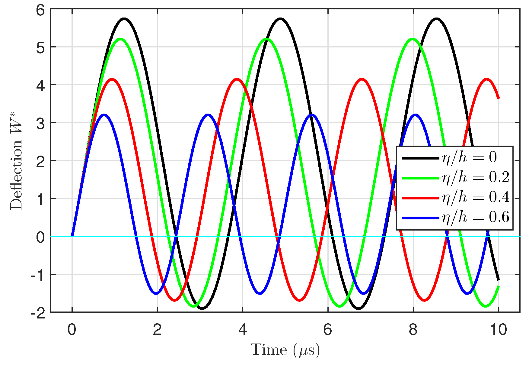
- The nonlinear dynamic deflection increases as the porosity coefficient, temperature, moisture, periodic load, and length-to-thickness ratio increase because the microtubes become weaker.
 - The material length scale parameter has a stiffening effect on the microtube, so the deflection decreases as the material parameter increases.
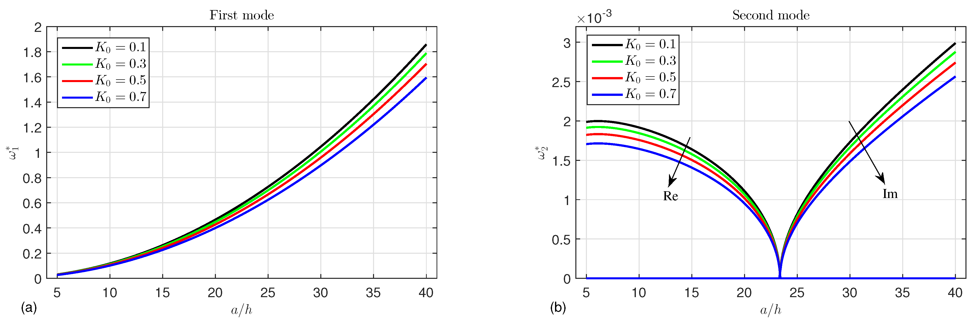
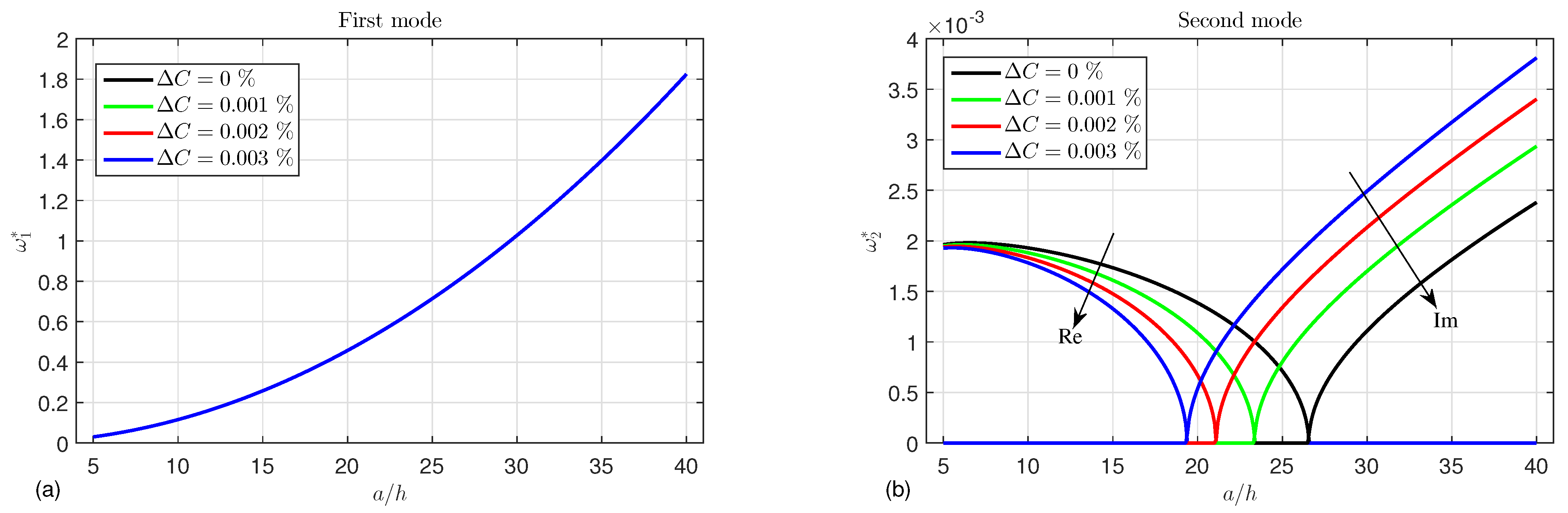
 - Since the presence of the porosities, temperature, moisture, and electric voltage leads to a decrement in the tube stiffness, the eigenfrequency decreases.
 - The wave frequency and phase velocity decrease with increasing porosity factor, indicating its dampening effect.
 - The present model can be used to transport petroleum or any other fluid in very hot environments because the presence of pores in the pipe wall reduces the effect of temperature.
 
Author Contributions
Conceptualization, F.H.H.A.M., M.F.S.A.M. and M.S.; methodology, F.H.H.A.M., M.F.S.A.M. and M.S.; software, M.S.; validation, F.H.H.A.M. and M.S.; formal analysis, F.H.H.A.M., M.F.S.A.M. and M.S.; investigation, F.H.H.A.M., M.F.S.A.M. and M.S.; resources, F.H.H.A.M., M.F.S.A.M. and M.S.; data curation, F.H.H.A.M., M.F.S.A.M. and M.S.; writing—original draft preparation, F.H.H.A.M., M.F.S.A.M. and M.S.; writing—review and editing, F.H.H.A.M., M.F.S.A.M. and M.S.; visualization, F.H.H.A.M., M.F.S.A.M. and M.S.; supervision, M.S.; project administration, F.H.H.A.M., M.F.S.A.M. and M.S.; funding acquisition, F.H.H.A.M., M.F.S.A.M. and M.S. All authors have read and agreed to the published version of the manuscript.
Funding
This work was supported by the Deanship of Scientific Research, Vice Presidency for Graduate Studies and Scientific Research, King Faisal University, Saudi Arabia (grant no. KFU242250).
Data Availability Statement
Data are contained within the article.
Conflicts of Interest
The authors declare no conflicts of interest.
References
- Rezaiee-Pajand, M.; Hozhabrossadati, S.M. Analytical and numerical method for free vibration of double-axially functionally graded beams. Compos. Struct. 2016, 152, 488–498. [Google Scholar] [CrossRef]
 - Sofiyev, A. On the solution of dynamic stability problem of functionally graded viscoelastic plates with different initial conditions in viscoelastic media. Mathematics 2023, 11, 823. [Google Scholar] [CrossRef]
 - Yang, S.; Sun, X.; Cai, Z. Isogeometric analysis for free vibration of functionally graded plates using a new quasi-3D spectral displacement formulation. Mathematics 2023, 11, 2660. [Google Scholar] [CrossRef]
 - Wang, Z.; Chen, S.h.; Han, W. The static shape control for intelligent structures. Finite Elem. Anal. Des. 1997, 26, 303–314. [Google Scholar] [CrossRef]
 - He, X.; Ng, T.; Sivashanker, S.; Liew, K. Active control of FGM plates with integrated piezoelectric sensors and actuators. Int. J. Solids Struct. 2001, 38, 1641–1655. [Google Scholar] [CrossRef]
 - Fakhari, V.; Ohadi, A.; Yousefian, P. Nonlinear free and forced vibration behavior of functionally graded plate with piezoelectric layers in thermal environment. Compos. Struct. 2011, 93, 2310–2321. [Google Scholar] [CrossRef]
 - Kulikov, G.; Plotnikova, S. A new approach to three-dimensional exact solutions for functionally graded piezoelectric laminated plates. Compos. Struct. 2013, 106, 33–46. [Google Scholar] [CrossRef]
 - Kulikov, G.M.; Plotnikova, S. Three-dimensional exact analysis of piezoelectric laminated plates via a sampling surfaces method. Int. J. Solids Struct. 2013, 50, 1916–1929. [Google Scholar] [CrossRef]
 - Mirzavand, B.; Eslami, M.; Reddy, J. Dynamic thermal postbuckling analysis of shear deformable piezoelectric-FGM cylindrical shells. J. Therm. Stress. 2013, 36, 189–206. [Google Scholar] [CrossRef]
 - Moradi-Dastjerdi, R.; Behdinan, K. Free vibration response of smart sandwich plates with porous CNT-reinforced and piezoelectric layers. Appl. Math. Model. 2021, 96, 66–79. [Google Scholar] [CrossRef]
 - Abazid, M.A.; Sobhy, M. Thermo-electro-mechanical bending of FG piezoelectric microplates on Pasternak foundation based on a four-variable plate model and the modified couple stress theory. Microsyst. Technol. 2018, 24, 1227–1245. [Google Scholar] [CrossRef]
 - Al Mukahal, F.H.; Abazid, M.A.; Sobhy, M. Investigating Electromechanical Buckling Response of FG-GPL-Reinforced Piezoelectric Doubly Curved Shallow Shells Embedded in an Elastic Substrate. Materials 2023, 16, 2975. [Google Scholar] [CrossRef] [PubMed]
 - Sobhy, M.; Radwan, A.F. Porosity and size effects on electro-hygrothermal bending of FG sandwich piezoelectric cylindrical shells with porous core via a four-variable shell theory. Case Stud. Therm. Eng. 2023, 45, 102934. [Google Scholar] [CrossRef]
 - Liu, Y.; Ma, W. Nonlinear Oscillations of a Composite Stepped Piezoelectric Cantilever Plate with Aerodynamic Force and External Excitation. Mathematics 2023, 11, 3034. [Google Scholar] [CrossRef]
 - Alsebai, F.; Al Mukahal, F.H.; Sobhy, M. Semi-analytical solution for thermo-piezoelectric bending of FG porous plates reinforced with graphene platelets. Mathematics 2022, 10, 4104. [Google Scholar] [CrossRef]
 - Zeeshan; Ahammad, N.A.; Shah, N.A.; Chung, J.D.; Khan, M.S. Computational and stability analysis of MHD time-dependent thermal reaction flow impinging on a vertical porous plate enclosing magnetic Prandtl number and thermal radiation effect. Mathematics 2023, 11, 1376. [Google Scholar] [CrossRef]
 - Talebitooti, R.; Zarastvand, M. The effect of nature of porous material on diffuse field acoustic transmission of the sandwich aerospace composite doubly curved shell. Aerosp. Sci. Technol. 2018, 78, 157–170. [Google Scholar] [CrossRef]
 - Melaibari, A.; Mohamed, S.A.; Assie, A.E.; Shanab, R.A.; Eltaher, M.A. Static response of 2D FG porous plates resting on elastic foundation using midplane and neutral surfaces with movable constraints. Mathematics 2022, 10, 4784. [Google Scholar] [CrossRef]
 - Melaibari, A.; Mohamed, S.A.; Assie, A.E.; Shanab, R.A.; Eltaher, M.A. Free vibration characteristics of bidirectional graded porous plates with elastic foundations using 2D-DQM. Mathematics 2022, 11, 46. [Google Scholar] [CrossRef]
 - Qin, Q.; Zheng, X.; Zhang, J.; Yuan, C.; Wang, T. Dynamic response of square sandwich plates with a metal foam core subjected to low-velocity impact. Int. J. Impact Eng. 2018, 111, 222–235. [Google Scholar] [CrossRef]
 - Cong, P.H.; Chien, T.M.; Khoa, N.D.; Duc, N.D. Nonlinear thermomechanical buckling and post-buckling response of porous FGM plates using Reddy’s HSDT. Aerosp. Sci. Technol. 2018, 77, 419–428. [Google Scholar] [CrossRef]
 - Sobhy, M. Size-dependent hygro-thermal buckling of porous FGM sandwich microplates and microbeams using a novel four-variable shear deformation theory. Int. J. Appl. Mech. 2020, 12, 2050017. [Google Scholar] [CrossRef]
 - Amir, S.; Arshid, E.; Arani, M.R.G. Size-dependent magneto-electro-elastic vibration analysis of FG saturated porous annular/circular micro sandwich plates embedded with nano-composite face sheets subjected to multi-physical pre loads. Smart Struct. Syst. Int. J. 2019, 23, 429–447. [Google Scholar]
 - Safaei, B.; Onyibo, E.C.; Hurdoganoglu, D. Thermal buckling and bending analyses of carbon foam beams sandwiched by composite faces under axial compression. Facta Univ. Ser. Mech. Eng. 2022, 20, 589–615. [Google Scholar] [CrossRef]
 - Yang, F.; Chong, A.; Lam, D.C.C.; Tong, P. Couple stress based strain gradient theory for elasticity. Int. J. Solids Struct. 2002, 39, 2731–2743. [Google Scholar] [CrossRef]
 - Ke, L.L.; Liu, C.; Wang, Y.S. Free vibration of nonlocal piezoelectric nanoplates under various boundary conditions. Phys. E Low-Dimens. Syst. Nanostruct. 2015, 66, 93–106. [Google Scholar] [CrossRef]
 - Zhang, B.; He, Y.; Liu, D.; Gan, Z.; Shen, L. A non-classical Mindlin plate finite element based on a modified couple stress theory. Eur. J. Mech.-A/Solids 2013, 42, 63–80. [Google Scholar] [CrossRef]
 - Bodaghi, M.; Shakeri, M. An analytical approach for free vibration and transient response of functionally graded piezoelectric cylindrical panels subjected to impulsive loads. Compos. Struct. 2012, 94, 1721–1735. [Google Scholar] [CrossRef]
 - Sobhy, M.; Alsaleh, F. Nonlinear bending of FG metal/graphene sandwich microplates with metal foam core resting on nonlinear elastic foundations via a new plate theory. Mech. Based Des. Struct. Mach. 2024, 52, 3842–3869. [Google Scholar] [CrossRef]
 - Chen, W.; Li, L.; Xu, M. A modified couple stress model for bending analysis of composite laminated beams with first order shear deformation. Compos. Struct. 2011, 93, 2723–2732. [Google Scholar] [CrossRef]
 - Jung, W.Y.; Han, S.C.; Park, W.T. A modified couple stress theory for buckling analysis of S-FGM nanoplates embedded in Pasternak elastic medium. Compos. Part B Eng. 2014, 60, 746–756. [Google Scholar] [CrossRef]
 - Reddy, J.; Pang, S. Nonlocal continuum theories of beams for the analysis of carbon nanotubes. J. Appl. Phys. 2008, 103, 023511. [Google Scholar] [CrossRef]
 - Tang, Y.; Xu, J.; Yang, T. Natural dynamic characteristics of a circular cylindrical Timoshenko tube made of three-directional functionally graded material. Appl. Math. Mech. 2022, 43, 479–496. [Google Scholar] [CrossRef]
 - Murmu, T.; Pradhan, S. Thermo-mechanical vibration of a single-walled carbon nanotube embedded in an elastic medium based on nonlocal elasticity theory. Comput. Mater. Sci. 2009, 46, 854–859. [Google Scholar] [CrossRef]
 - Ebrahimi, F.; Salari, E. Thermo-mechanical vibration analysis of a single-walled carbon nanotube embedded in an elastic medium based on higher-order shear deformation beam theory. J. Mech. Sci. Technol. 2015, 29, 3797–3803. [Google Scholar] [CrossRef]
 - Ansari, R.; Sahmani, S. Small scale effect on vibrational response of single-walled carbon nanotubes with different boundary conditions based on nonlocal beam models. Commun. Nonlinear Sci. Numer. Simul. 2012, 17, 1965–1979. [Google Scholar] [CrossRef]
 - Ke, L.L.; Wang, Y.S.; Yang, J.; Kitipornchai, S. Free vibration of size-dependent magneto-electro-elastic nanoplates based on the nonlocal theory. Acta Mech. Sin. 2014, 30, 516–525. [Google Scholar] [CrossRef]
 - Ke, L.L.; Wang, Y.S.; Wang, Z.D. Nonlinear vibration of the piezoelectric nanobeams based on the nonlocal theory. Compos. Struct. 2012, 94, 2038–2047. [Google Scholar] [CrossRef]
 - Zenkour, A.; Sobhy, M. Thermal buckling of various types of FGM sandwich plates. Compos. Struct. 2010, 93, 93–102. [Google Scholar] [CrossRef]
 - Zeng, S.; Wang, B.; Wang, K. Nonlinear vibration of piezoelectric sandwich nanoplates with functionally graded porous core with consideration of flexoelectric effect. Compos. Struct. 2019, 207, 340–351. [Google Scholar] [CrossRef]
 - Yaghoobi, H.; Taheri, F. Analytical solution and statistical analysis of buckling capacity of sandwich plates with uniform and non-uniform porous core reinforced with graphene nanoplatelets. Compos. Struct. 2020, 252, 112700. [Google Scholar] [CrossRef]
 - Bamdad, M.; Mohammadimehr, M.; Alambeigi, K. Analysis of sandwich Timoshenko porous beam with temperature-dependent material properties: Magneto-electro-elastic vibration and buckling solution. J. Vib. Control 2019, 25, 2875–2893. [Google Scholar] [CrossRef]
 - Brush, D.O.; Almroth, B.O.; Hutchinson, J. Buckling of bars, plates, and shells. J. Appl. Mech. 1975, 42, 911. [Google Scholar] [CrossRef]
 - Shariat, B.S.; Eslami, M. Buckling of thick functionally graded plates under mechanical and thermal loads. Compos. Struct. 2007, 78, 433–439. [Google Scholar] [CrossRef]
 - Li, L.; Hu, Y.; Ling, L. Wave propagation in viscoelastic single-walled carbon nanotubes with surface effect under magnetic field based on nonlocal strain gradient theory. Phys. E Low-Dimens. Syst. Nanostruct. 2016, 75, 118–124. [Google Scholar] [CrossRef]
 - Ilyashenko, A.V.; Kuznetsov, S.V. Pochhammer–Chree waves: Polarization of the axially symmetric modes. Arch. Appl. Mech. 2018, 88, 1385–1394. [Google Scholar] [CrossRef]
 - Reddy, J. Microstructure-dependent couple stress theories of functionally graded beams. J. Mech. Phys. Solids 2011, 59, 2382–2399. [Google Scholar] [CrossRef]
 
Disclaimer/Publisher’s Note: The statements, opinions and data contained in all publications are solely those of the individual author(s) and contributor(s) and not of MDPI and/or the editor(s). MDPI and/or the editor(s) disclaim responsibility for any injury to people or property resulting from any ideas, methods, instructions or products referred to in the content.  | 
© 2024 by the authors. Licensee MDPI, Basel, Switzerland. This article is an open access article distributed under the terms and conditions of the Creative Commons Attribution (CC BY) license (https://creativecommons.org/licenses/by/4.0/).