Abstract
In this paper, a novel data transmission scheme, interference perceptual multi-modulation (IP-MM), is proposed for full-duplex (FD) systems. In order to unlink the conventional uplink (UL) data transmission using a single modulation and coding scheme (MCS) over the entire assigned UL bandwidth, IP-MM enables the transmission of UL data channels based on multiple MCS levels, where a different MCS level is applied to each subband of UL transmission. In IP-MM, a deep convolutional neural network is used for MCS-level prediction for each UL subband by estimating the potential residual self-interference (SI) according to the downlink (DL) resource allocation pattern. In addition, a subband-based UL transmission procedure is introduced from a specification point of view to enable IP-MM-based UL transmission. The benefits of IP-MM are verified using simulations, and it is observed that IP-MM achieves approximately throughput gain compared to the conventional UL transmission scheme.
MSC:
94A12
1. Introduction
Since the Third-Generation Partnership Project (3GPP) completed the first series of specifications for the fifth-generation (5G) New Radio (NR) standard, 5G commercial systems have been successfully deployed around the world [1,2,3]. The 5G NR standards have continued to evolve over the past few years, and are currently evolving towards 5G-Advanced. Recently, 3GPP has completed the Release 18 project, which corresponds to the 5G-Advanced launch [4,5,6,7]. From the physical layer point of view, the evolution of duplex operation, including full-duplex (FD) technology, has been investigated to improve the performance of 5G in terms of throughput, coverage, and connectivity [7]. As a result of the investigation into Release 18, the technical report (TR) 38.858 was endorsed, encompassing general aspects of FD schemes, analysis of the performance and its feasibility, as well as potential enhancements [8]. Additionally, as part of the Release 19 package, the work item for duplex evolution has been approved [9]. In Release 19, the standardization effort for FD technology primarily focuses on supporting semi-static/dynamic FD operation and addressing the cross-link interference problems [10]. Beyond 5G, FD is now considered a promising technology to promote the emergence of 6G [11,12].
The FD technique enables the simultaneous transmission and reception of downlink (DL) and uplink (UL) signals in the same time and frequency resources [13,14,15]. Thus, FD can theoretically double the spectral efficiency compared to the conventional half-duplex (HD) operation. The major challenge of FD-enabled cellular communication systems is the performance degradation in the UL data rate caused by the self-interference (SI) phenomenon, i.e., the transmitted DL signals cause unwanted interference to the received UL signals. To make the FD operation feasible, numerous studies with respect to SI estimation [16,17,18,19,20,21,22,23,24,25,26] and SI cancellation (SIC) [27,28,29,30,31,32,33,34] have been conducted.
Regarding the SI estimation methods, Refs. [16,17,18,19] have examined how the nonlinearities and phase noise in transmit and receive power amplifiers affect digital SIC techniques. Ref. [20] proposed an efficient SI channel estimation algorithm based on partial training for FD massive multiple-input–multiple-output (MIMO) systems. The authors of [21] developed a novel one-block training scheme based on a maximum likelihood estimator to estimate the channels between the nodes as well as the residual SI channel simultaneously for FD two-way relays. Ref. [22] conducted a study on joint estimation of SI channel and RF impairments for orthogonal frequency-division multiplexing (OFDM) full-duplex systems. In [23,24,25,26], several SI estimation schemes based on a deep learning approach were investigated. Refs. [23,24,25] utilized deep neural networks for the reconstruction of the nonlinear SI components to mitigate SI signals in FD systems. In [26], a pilot-aided linear minimum mean-squared error (LMMSE) estimator was developed to jointly estimate the channel, phase noise, and in-phase/quadrature-phase imbalance for multicarrier MIMO FD systems.
The SIC techniques can be applied individually in analog and digital domains as well as in combination [14,27,35]. The radio frequency (RF) signals are initially attenuated in the analog domain to accommodate the dynamic range of the analog-to-digital converter (ADC). Subsequently, the residual SI is further suppressed in the digital domain. Numerous digital nonlinear SIC techniques have been proposed that can be classified into time-domain, frequency-domain, and spatial-domain approaches [28,29,30,31,32,33,34]. Time-domain nonlinear SIC approaches were investigated in [28,29]. In particular, in [28], iterative nonlinear SIC under mixer imbalance and amplifier nonlinearity was proposed. Ref. [29] introduced a low-complexity SIC technique in multiple carrier and multiple access systems that utilizes the whole band directly during digital sampling. Refs. [30,31] proposed frequency-domain SIC techniques. Ref. [30] focused on developing a low-complexity algorithm and Ref. [31] utilized basis function selection of frequency-domain Hammerstein SIC. Space-domain SICs were studied in [32,33,34]. In [32], an iterative beamforming algorithm was proposed for multipair FD relay systems. Ref. [33] proposed a beamforming technique based on channel statistics for multi-set space–time shift keying-based FD millimeter wave communication systems. Ref. [34] studied joint optimization of beamforming and phase adjustment for FD relay systems with intelligent reflecting surfaces.
Most previous studies on FD have focused on the development of SIC algorithms. Unlike previous studies, this study focuses on the further optimization of UL data transmission under a given residual SI level after SIC. To this end, the drawbacks and limitations of the conventional UL transmission scheme specified in 5G NR [36] are analyzed. In NR, a physical uplink shared channel (PUSCH) corresponding to the UL data channel is transmitted based on a single MCS level. Given that the FD operation is employed, the BS requires that the residual SI level be identified beforehand to estimate the effective signal-to-interference-plus-noise ratio (SINR) and corresponding MCS level. However, estimating the instantaneous residual SI level is challenging because of the complicated nonlinearities in the transceiver [21,30]. Moreover, the residual SI level varies dynamically depending on the frequency-domain resource allocation of the DL signal. Although the residual SI level is known at the BS, the conventional UL transmission scheme still suffers from a huge UL throughput degradation because a conservative MCS level is selected to meet the target error rate. Therefore, it is necessary to develop a more efficient UL transmission scheme for FD systems.
Motivated by the above considerations, in this paper, a novel UL data transmission scheme, interference perceptual multi-modulation (IP-MM), is proposed for FD systems. The proposed IP-MM enables the transmission of UL data channels based on multiple MCS levels, where a different MCS level is applied to each subband of the UL transmission. To determine the MCS levels, a deep convolutional neural network (CNN) is developed. The CNN selects an optimized MCS level for a given subband using channel information and DL resource allocation information as input. A new PUSCH transmission scheme based on the IP-MM is then proposed from a specification point of view.
The main contributions are summarized as follows:
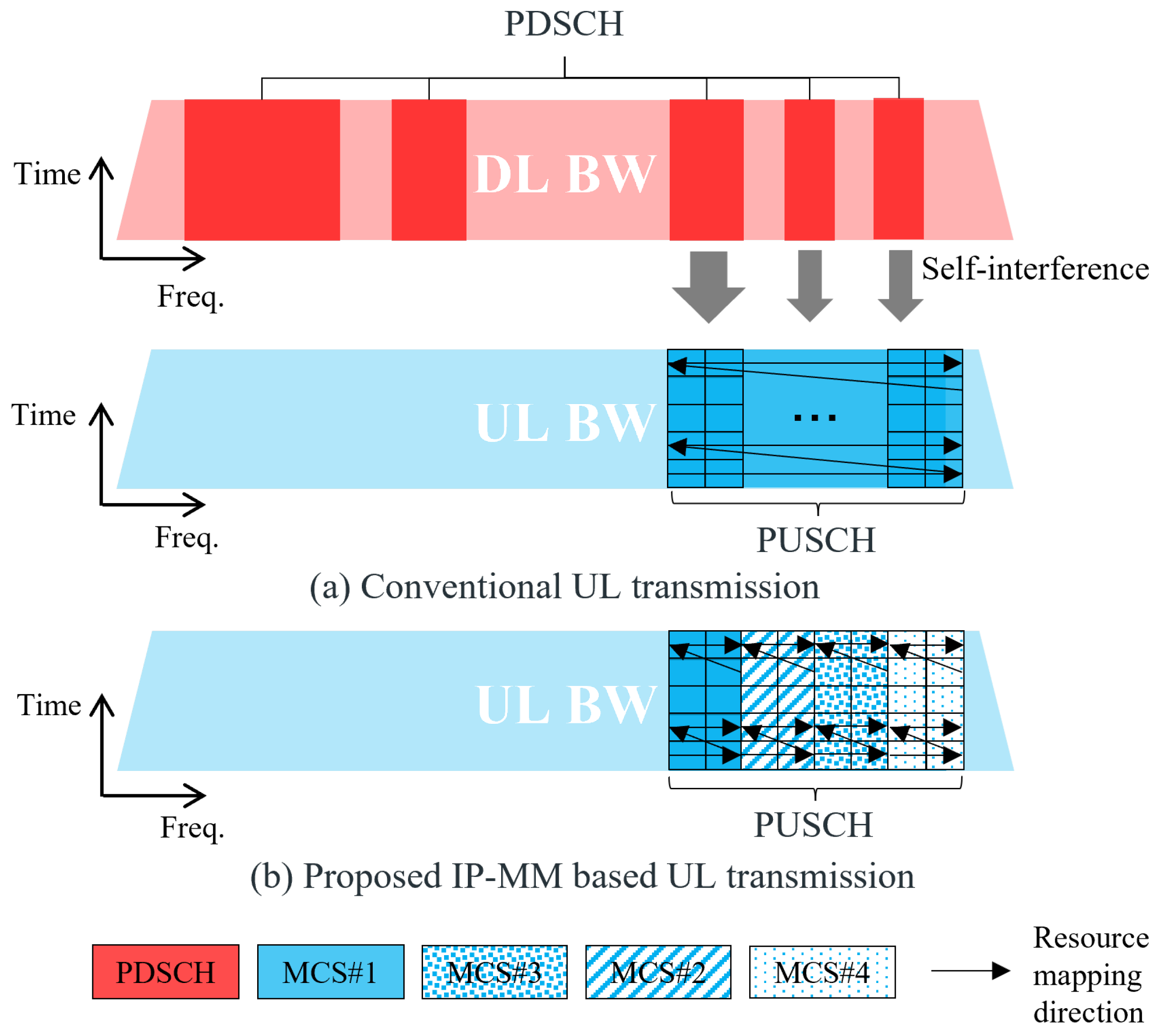
- First, an IP-MM scheme designed to enhance the robustness of UL transmission in FD systems is proposed. The proposed IP-MM scheme employs multiple MCS levels for a PUSCH, where the MCS levels are optimized depending on the SI levels for each subband. To this end, the 5G specification related to PUSCH transmission is analyzed, and the limitations of the current scheme when it directly employed in FD systems are identified. Furthermore, a new PUSCH transmission procedure based on the proposed IP-MM is introduced.
- A CNN architecture is developed to determine the optimal MCS level for PUSCH. The proposed CNN uses PDSCH resource allocation information and channel state information as input signals. Then, the regression layer of CNN selects the optimal MCS levels depending on the SI levels.
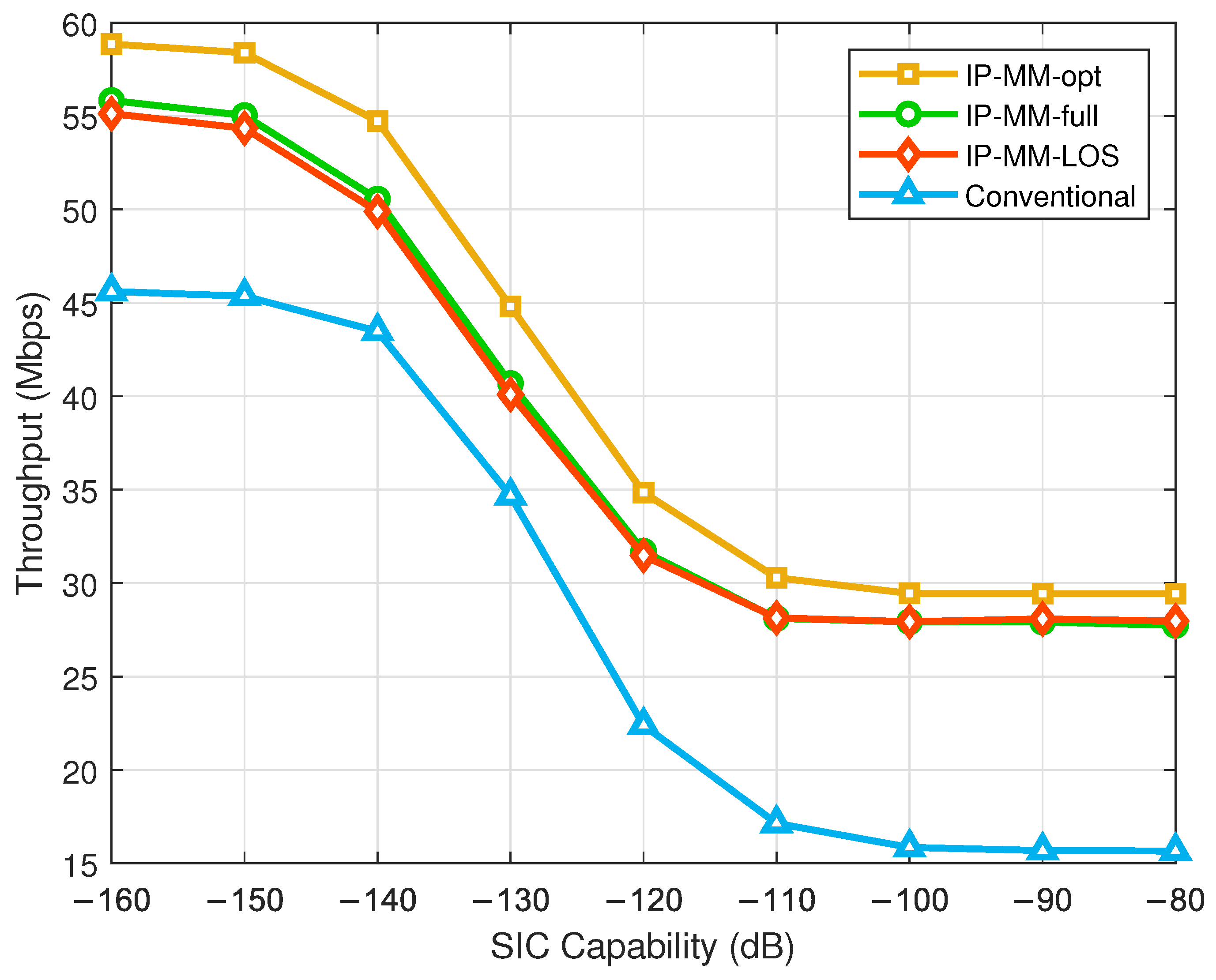
- The advantages of the proposed IP-MM scheme over the conventional scheme are verified through various simulations. Notably, the proposed IP-MM shows robust performance even with limited channel knowledge. The IP-MM scheme leads to a substantial reduction in the SIC requirements for FD systems.
The remainder of this paper is organized as follows. In Section 2, the system model is introduced. In Section 3, the conventional UL transmission scheme for 5G NR is briefly reviewed, and the proposed IP-MM is introduced in Section 4. The performance of the IP-MM is evaluated in Section 5. Finally, Section 6 summarizes the results of this study.
2. System Model
As a waveform, conventional cyclic prefix OFDM (CP-OFDM) is considered for both DL and UL [36]. The transmitted complex digital signal on the kth subcarrier in an OFDM symbol is denoted by . After operating the K-point inverse fast Fourier transform (IFFT), a time-domain baseband CP-OFDM signal is generated. The DL signal and UL signal are generated at the BS and UE, respectively.
The DL signal is transmitted after passing through the digital-to-analog converter (DAC) and the power amplifier (PA). At the same time, the DL signal flows into the BS receiving antenna so that the UL and DL signals are received together. The DL signal power level is suppressed by antenna domain SIC techniques such as antenna isolation or active cancellation at the radio frequency (RF) front-end [14]. The received DL and UL signals are adjusted by using a low noise amplifier (LNA) and they are converted to digital signal through the analog-to-digital converter (ADC). In order to eliminate DL signal from the desired UL signal in digital domain, digital SIC techniques can be applied [14,30]. After that, the UL signal is demodulated and decoded.
Details of nonlinearity models and channel models are described in the following subsections.
2.1. Transmitter Nonlinearity
Considering the strong nonlinearity of the PA and the relatively weak nonlinearities of the DAC and mixer, the generalized memory polynomial (MP) model is used for modeling PA nonlinearity [30,37]. Then, the output signal of the PA is given by
where denotes the impulse response for the pth order nonlinearity, P is the highest nonlinearity order, and M denotes the memory depth of the PA.
2.2. Channel Model
The output signal of PA is transmitted over the L-tap multipath SI channel. Denoting for as the impulse response of the SI channel, the received SI signal is given by
The SI channel is typically modeled as Rician fading, which is composed of two parts: (i) strong near-field components representing line-of-sight (LOS) paths and (ii) weak far-field components of the reflected non-LOS (NLOS) paths [20].
The received signal at the LNA input is given by
where
is the -tap UL channel and w is the additive white Gaussian noise (AWGN). The UL channel is modeled as Rayleigh fading.
2.3. Receiver Nonlinearity
The receiver nonlinearity is dominated by the strong nonlinearity of the LNA [37]. Typically, the nonlinear distortion of the receiver is much lower than that of the transmitter, since the residual SI that enters the receive chain after analog SIC is much lower than the third-order input intercept point (IIP3) [30,37]. Assuming a power series for modeling nonlinearity of the LNA, the output of LNA is given by
where Q is the highest nonlinear order and is the q-th order coefficient of the LNA nonlinear model. is defined as . is effective noise following an independent zero-mean Gaussian noise at the LNA output [37]. (a) holds for that the strength of the linear component of the desired signal is much greater than the nonlinear components [30].
2.4. SINR Formulation
Assuming that SIC techniques are applied [14], the LNA output signal in (5) can be rewritten as
where is a power scaling factor, which reflects the capability of the SIC techniques. After removing the CP and K-point FFT, the received signal on the kth subcarrier can be written as
where , , and are the frequency-domain representations of , , and , respectively. Then, the received SINR on the kth subcarrier is given by
where denotes the effective noise power.
3. Conventional UL Transmission Scheme
In 5G NR, UL data are encoded and modulated based on a single MCS level and transmitted via PUSCH, as shown in Figure 1a [36]. To determine the MCS level for a PUSCH, the BS first estimates the UL channel based on the UL reference signal (RS) transmitted by the UE. Then, the BS determines the time and frequency resources for scheduling PUSCH. Subsequently, the effective SINR is calculated for a given set of subcarriers to be scheduled to determine the MCS level for the PUSCH. To obtain an effective SINR , exponential effective SINR mapping (EESM) is used [38]. Assuming that the BS can accurately determine the residual SI level for all PUSCH resources, the SINR on the kth subcarrier is equal to (8). Then, is given by
where is the set of subcarriers of interest to be averaged, is the cardinality of , and is a coefficient calibrated using link-level simulations to fit the compression function to the AWGN block error rate (BLER) results. Based on , one representative MCS satisfying the target BLER is selected. The BS provides PUSCH resource allocation information and the MCS level to the UE via downlink control information (DCI). From the indicated MCS level, the UE extract the modulation order () and coding rate (C). Subsequently, the transport block size (TBS) is determined as . Based on the selected MCS, the TB is encoded and modulated into complex symbols. These modulated symbols are mapped to the physical resources corresponding to the resources indicated by the DCI. The mapping to the resource elements (REs) allocated for PUSCH is in increasing order of first index k over the assigned resource blocks (RBs) and then index j. Here, k is the subcarrier index, j is the OFDM symbol index, and RB corresponds to a set of REs, in which 1 RB consists of 12 REs. Finally, the UE transmits PUSCH to the BS.
Figure 1.
Illustration of UL transmission in FD systems: (a) conventional UL transmission scheme and (b) proposed IP-MM based UL transmission scheme.
4. Proposed IP-MM Scheme
The conventional UL transmission scheme based on a single MCS level has several critical problems, as follows.
- The conventional scheme incurs performance degradation in terms of UL throughput due to the use of single MCS. As described in (9), the SINR is averaged over the subcarriers in which the PUSCH is scheduled for MCS determination. In this procedure, a conservative MCS level is selected to satisfy the target BLER, although the UL signal experiences different levels of residual SI depending on the subcarriers.
- For the conventional scheme, the BS needs to predict the received SINR over all the UL subcarriers by estimating the instantaneous residual SI level. As in (8), the residual SI is the superposition of a number of nonlinear components passing through the PA nonlinear channel, SI channel, and LNA nonlinear channel. It is very challenging to estimate the nonlinear channel coefficients and SI channel because this typically requires complicated algorithms based on polynomial expansions [21].
- The residual SI level on a subcarrier is affected by the frequency domain resource allocation of a physical downlink shared channel (PDSCH) corresponding to the DL signal, as illustrated in Figure 1. The residual SI level on a subcarrier could be very different depending on whether the PDSCH is assigned to the subcarrier or not (5G NR supports two different types of frequency-domain resource allocation for PDSCH and PUSCH [36]. Type 0 corresponds to the distributed mapping and type 1 corresponds to the contiguous mapping. Typically, type 0 is used for PDSCH while type 1 is used for PUSCH). Since the PDSCH resource allocation is dynamically changed in every time slot, it is very difficult to correctly estimate the instantaneous SI level.
Based on the above observations, an IP-MM based UL transmission scheme is developed, as shown in Figure 1b. To resolve the first issue, multiple MCS levels are applied for the PUSCH transmission. The entire UL frequency resource allocated for a PUSCH is divided into several subbands, and different MCS levels are applied for each subband. The second and third issues are resolved by adopting a deep learning algorithm. Instead of estimating the residual SI level on each subcarrier, the deep learning algorithm directly calculates the optimal MCS level for each subband.
Details of the proposed IP-MM scheme are described in the following subsections.
4.1. Deep Learning Algorithm for MCS Determination
MCS determination uses a CNN based on a regression approach with the network structures presented in Table 1. The CNN structure is considered to give meaning to the spatial location of bitmap, UL channel, and SI channel information according to subbands and to extract the spatial characteristics as much as possible by using 2D filters for MCS determination. The CNN determines the MCS levels for all subbands using the bitmap for PDSCH resource allocation, the magnitude of the UL channel , and the magnitude of the SI channel as the input signals. The size of the bitmap is bits, where is the number of RB groups (RBGs) allocated for the PDSCH and an RBG consists of multiple RBs [36]. As the target signals of CNN, the selected MCS levels based on for are used, where is the number of subbands. Meanwhile, is the effective SINR for the ith subband obtained from (9) by replacing with where is a set of REs within the ith subband. During the learning process, the network weights of the CNN are optimized to reduce the root-mean-square error between the estimated and target MCS levels. For the regression problem, 32 MCS levels [36] are normalized to the range for fast and accurate training.
Table 1.
Structure of the employed CNN for the MCS determination.
The CNN consists of an input layer, three convolutional layers, three batch normalization layers, three polling layers, and a fully connected (FC) layer. In the input layer, a signal of size attaching the bitmap for the PDSCH resource allocation with a size of , magnitude of with size , and magnitude of of size is used as the input of the CNN, where is the number of total RBs. In the convolutional layer, the number of convolution filters for the first, second, and third layers is set to 32, 48, and 64 with the filter size , respectively. Batch normalization layers are used between the convolutional layer and the activation function [39]. For the pooling layer, max and average pooling are considered with filter size, a stride size of 2, and no zero-padding. The exponential linear unit (ELU) is used as the activation function layer, except for the FC layer, where the sigmoid is employed [40]. Finally, the FC layer is used to connect all neurons from the previous convolutional layer to the output neurons of size and attach them to the regression layer. Based on the values calculated in the regression layer, the CNN determines the MCS levels for all subbands by scaling the output values with size ranging from the regression layer to the range and selecting the closest MCS levels for all subbands between the scaled values and set of MCS levels.
4.2. IP-MM Based UL Transmission Procedure
After determining the MCS levels for all subbands, the BS sends the corresponding UL scheduling information to the UE. Based on the scheduling information, the TBS is calculated as where , and are the modulation order, coding rate, and number of REs for subband i, respectively. Because MCS i is applied to subband i, the modulated symbols of the TB corresponding to MCS i should be mapped within subband i. Therefore, the resource mapping should be changed from the original mapping used in the conventional scheme. As shown in Figure 1b, the modulated symbols of a TB are mapped to the physical resources in the frequency-first and time-second manner within subband i. After resource mapping for the subband i is performed, resource mapping is continued for the next subband until all subbands are mapped. In terms of DL control signaling, the IP-MM requires additional bits in a DCI to indicate multiple MCS levels for a PUSCH. Consequently, the IP-MM may lead to an increase in DL control signaling overhead. Addressing this concern requires the exploration of a new DCI design minimizing signaling overhead. This remains the topic of future research because it is beyond the scope of current research.
5. Simulation Results
In this section, the simulation results are presented to verify the benefits of the proposed IP-MM scheme. For the proposed IP-MM, it is assumed that the UL resources are equally divided into subbands. For PA nonlinearity, it is assumed that and , and the coefficients are adopted from [30] given by
For the LNA nonlinearity, it is assumed that , and the coefficients in [37] are used, which are given by
For the UL and SI channels, tapped delay line (TDL) models C and D are assumed, respectively [41]. The first tap in TDL model D follows a Rician fading distribution because of the LOS path. The remaining simulation parameters are summarized in Table 2.
Table 2.
Simulation parameters.
For deep learning, 200,000 channel realizations are generated, and 80% and 20% of the realizations are used as the training and validation sets, respectively. The CNN is trained over 50 epochs using the Adam optimizer, with an initial learning rate of [42]. During the training process, a mini-batch gradient descent algorithm with a batch size of 64 is considered, which splits the training dataset into small batches to estimate the error gradient before the model weights are updated.
For comparison, the performance of the conventional scheme with an ideal SINR in which the BS accurately determines for all subcarriers is evaluated together. Two types of IP-MM are evaluated for the proposed IP-MM: (i) IP-MM with full knowledge (IP-MM-full) and (ii) IP-MM with partial knowledge, where only the LOS component is available (IP-MM-LOS). The upper-bound performance of IP-MM with optimal MCS levels (IP-MM-opt) is also plotted.
Figure 2 shows cumulative distribution function (CDF) of the effective SINRs for the conventional scheme and the proposed IP-MM. For the conventional scheme, the effective SINR, , is obtained as described in (9), i.e., by averaging the SINRs over the whole REs within PUSCH transmission bandwidth. On the other hand, for the proposed IP-MM, the effective SINR is obtained for each subband, i.e., is calculated by averaging the SINRs over REs in the ith subband. In Figure 2, it is observed that the mean of the effective SINR of the proposed IP-MM is greater than that of the conventional scheme . Moreover, it is observed that the effective SINR of IP-MM is improved as the number of subbands increases due to the diversity effect. Therefore, the proposed IP-MM scheme can be expected to provide UL throughput gain over the conventional scheme.
Figure 2.
CDF of effective SINR according to when and dB.
Figure 3 provides some examples of MCS determinations for the conventional and proposed IP-MM schemes depending on when and dB. As introduced in Section 3, a single MCS level is determined based on for the conventional scheme. For the proposed IP-MM, the MCS level is determined per subband, i.e., the ith MCS level for the ith subband is determined based on . As described in Figure 3, MCS levels for some subbands of the proposed IP-MM scheme are determined by higher values than the MCS level of the conventional scheme. For example, for IP-MM scheme when , the MCS levels for subbands 4, 5, 6 and 8 are determined as 6, 6, 5, and 4, respectively, while the MCS level of the conventional scheme is determined as 3. As a result, the IP-MM scheme can potentially improve the UL throughput compared with the conventional scheme by transmitting parts of UL data with a higher MCS level.
Figure 3.
Examples of MCS determination according to when and dB.
Figure 4 shows the UL throughput performances according to when and dB. It is observed that the performance of IP-MM improves as increases. This is because more optimized MCS levels can be applied per subband in finer granularity as increases. For , the proposed IP-MM achieves approximately 20% UL throughput gain compared with the conventional scheme. IP-MM-full and IP-MM-LOS, which select the MCS levels based on the proposed CNN algorithm, can achieve approximately 90% of the performance of the IP-MM-opt. Notably, the performance of IP-MM-LOS is similar to that of IP-MM-full. Therefore, it can be concluded that knowledge of the LOS component for the SI channel is sufficient for deep learning to determine the MCS levels.
Figure 4.
UL throughput performances according to when and dB.
Figure 5 illustrates the UL throughput performances according to when and dB. The performance of IP-MM and conventional schemes decreases with . This occurs because of that the UL signal suffers from a stronger SI as increases since a larger implies that more RBGs are allocated for PDSCH. For the considered regime, the proposed IP-MM outperforms the conventional scheme. It is observed that the performance gain of the IP-MM scheme over the conventional scheme increases as decreases, and it decreases as increases. Specifically, the proposed IP-MM scheme achieves approximately 25% and 4% gain when and , respectively. This is because the advantage of employing multiple MCS levels for a PUSCH is maximized when each subband is suffering from a different level of SI, i.e., the , for is different. As decreases, the difference among subband SINRs, i.e., , for will be large because certain subbands may encounter significant SI, while others might experience almost no SI. On the other hand, as increases, most of the subbands are affected by strong SI. Therefore, the performance gain of the proposed IP-MM scheme becomes marginal in response to a large regime.
Figure 5.
UL throughput performances according to when and dB.
Figure 6 describes the UL throughput according to when and . In general, as the SIC capability decreases (i.e., increases), the UL throughput decreases. The proposed IP-MM scheme achieves approximately 14~70% gain in terms of throughput compared with the conventional scheme. Notably, the proposed IP-MM scheme shows significant improvement regardless of the SIC capability. To be specific, the IP-MM-full achieves 22% gain at dB (in a high SIC-capability regime), 14% gain at dB (in a middle SIC-capability regime), and 70% gain at dB (in a low SIC-capability regime). In particular, the benefit of the IP-MM scheme is maximized in the low SIC-capability regime. In other words, the IP-MM can more effectively meet the minimum UL throughput requirement for FD systems with a limited SIC capability. From the other point of view, the proposed IP-MM can be used for alternating solutions to relax the SIC requirement. It is observed that the proposed IP-MM requires 8 dB less SIC capability than the conventional scheme to achieve the same UL throughput of 35 Mbps. This implies that, for the IP-MM scheme, the SIC requirement can be further relaxed to achieve the target UL throughput.
Figure 6.
UL throughput according to when and .
6. Conclusions
In this paper, a novel UL transmission scheme, IP-MM, was proposed for FD systems. In IP-MM, a UL data channel was transmitted based on multiple MCS levels, where different MCS level was applied to each subband of the UL transmission. To determine the MCS level for each UL subband, a CNN algorithm was developed, which utilized the channel information and the DL resource allocation pattern. Additionally, we proposed using a subband-based UL transmission procedure from a specification point of view to enable IP-MM-based UL transmission. The benefits of IP-MM were verified using simulations, and it was observed that IP-MM achieved approximately UL throughput gain compared to the conventional scheme.
Author Contributions
Conceptualization, T.K.; methodology, T.K. and G.K.; software, T.K. and G.K.; validation, T.K. and G.K.; formal analysis, G.K.; investigation, T.K. and G.K.; resources, T.K. and G.K.; data curation, T.K. and G.K.; writing—original draft preparation, T.K. and G.K.; writing—review and editing, T.K. and G.K.; visualization, T.K.; supervision, T.K.; project administration, T.K. and G.K.; funding acquisition, T.K. and G.K. All authors have read and agreed to the published version of the manuscript.
Funding
This work was supported by the National Research Foundation of Korea (NRF) Grant through the Korea Government [Ministry of Science and Information and Communication Technology (MSIT)] under Grant NRF-2022R1F1A1064106 for Taehyoung Kim. Also, this research was financially supported by Hansung University for Gyuyeol Kong.
Data Availability Statement
The data will be made available by the authors on request.
Conflicts of Interest
The authors declare no conflicts of interest.
References
- Kim, Y.; Kim, Y.; Oh, J.; Ji, H.; Yeo, J.; Choi, S.; Ryu, H.; Noh, H.; Kim, T.; Sun, F.; et al. New Radio (NR) and its evolution toward 5G-Advanced. IEEE Wirel. Commun. 2019, 26, 2–7. [Google Scholar] [CrossRef]
- Agiwal, M.; Roy, A.; Saxena, N. Next Generation 5G Wireless Networks: A Comprehensive Survey. IEEE Commun. Surv. Tutor. 2016, 18, 1617–1655. [Google Scholar] [CrossRef]
- Shafi, M.; Molisch, A.F.; Smith, P.J.; Haustein, T.; Zhu, P.; De Silva, P.; Tufvesson, F.; Benjebbour, A.; Wunder, G. 5G: A Tutorial Overview of Standards, Trials, Challenges, Deployment, and Practice. IEEE J. Sel. Areas Commun. 2017, 35, 1201–1221. [Google Scholar] [CrossRef]
- Ghosh, A.; Maeder, A.; Baker, M.; Chandramouli, D. 5G Evolution: A View on 5G Cellular Technology Beyond 3GPP Release 15. IEEE Access 2019, 7, 127639–127651. [Google Scholar] [CrossRef]
- Chen, W.; Lin, X.; Lee, J.; Toskala, A.; Sun, S.; Chiasserini, C.F.; Liu, L. 5G-Advanced toward 6G: Past, Present, and Future. IEEE J. Sel. Areas Commun. 2023, 41, 1592–1619. [Google Scholar] [CrossRef]
- Liberg, O.; Hoymann, C.; Tidestav, C.; Larsson, D.C.; Rahman, I.; Blasco, R.; Falahati, S.; Blankenship, Y. Introducing 5G Advanced. IEEE Commun. Stand. Mag. 2024, 8, 52–57. [Google Scholar] [CrossRef]
- Summary for RAN Rel-18 Package, Document RP-213469, 3GPP. December 2021. Available online: https://www.3gpp.org/ftp/TSG_RAN/TSG_RAN/TSGR_94e/Docs/RP-213469.zip (accessed on 1 May 2024).
- TSG RAN. Study on Evolution of NR Duplex Operation (Release 18), Document TR 38.858 V18.0.0, 3GPP. December 2023. Available online: https://www.3gpp.org/ftp/Specs/archive/38_series/38.858/38858-i00.zip (accessed on 1 May 2024).
- Summary for RAN Rel-19 Package: RAN1/2/3-led, Document RP-232745, 3GPP. December 2023. Available online: https://www.3gpp.org/ftp/tsg_ran/TSG_RAN/TSGR_102/Docs/RP-232745.zip (accessed on 1 May 2024).
- Moderator’s Summary for REL-19 RAN1 Topic Duplex Evolution, Document RP-232613, 3GPP. September 2023. Available online: https://www.3gpp.org/ftp/tsg_ran/TSG_RAN/TSGR_101/Docs/RP-232613.zip (accessed on 1 May 2024).
- Smida, B.; Sabharwal, A.; Fodor, G.; Alexandropoulos, G.C.; Suraweera, H.A.; Chae, C.-B. Full-duplex wireless for 6G: Progress brings new opportunities and challenges. IEEE J. Sel. Areas Commun. 2023, 41, 2729–2750. [Google Scholar] [CrossRef]
- Wang, C.X.; You, X.; Gao, X.; Zhu, X.; Li, Z.; Zhang, C.; Wang, H.; Huang, Y.; Chen, Y.; Haas, H.; et al. On the road to 6G: Visions, requirements, key technologies, and testbeds. IEEE Commun. Surv. Tutor. 2023, 25, 905–974. [Google Scholar] [CrossRef]
- Kim, D.; Lee, H.; Hong, D. A survey of in-band full-duplex transmission: From the perspective of PHY and MAC layers. IEEE Commun. Surv. Tutor. 2015, 17, 2017–2046. [Google Scholar] [CrossRef]
- Kolodziej, K.E.; Perry, B.T.; Herd, J.S. In-band full-duplex technology: Techniques and systems survey. IEEE Trans. Microw. Theory Tech. 2019, 67, 3025–3041. [Google Scholar] [CrossRef]
- Sabharwal, A.; Schniter, P.; Guo, D.; Bliss, D.W.; Rangarajan, S.; Wichman, R. In-Band Full-Duplex Wireless: Challenges and Opportunities. IEEE J. Sel. Areas Commun. 2014, 32, 1637–1652. [Google Scholar] [CrossRef]
- Korpi, D.; Anttila, L.; Syrjälä, V.; Valkama, M. Widely linear digital self-interference cancellation in direct-conversion full-duplex transceiver. IEEE J. Sel. Areas Commun. 2014, 32, 1674–1687. [Google Scholar] [CrossRef]
- Ahmed, E.; Eltawil, A. All-digital self-interference cancellation technique for full-duplex systems. IEEE Trans. Wirel. Commun. 2015, 14, 3519–3532. [Google Scholar] [CrossRef]
- Quan, X.; Liu, Y.; Shao, S.; Huang, C.; Tang, Y. Impacts of phase noise on digital self-interference cancellation in full-duplex communications. IEEE Trans. Signal Process. 2017, 65, 1881–1893. [Google Scholar] [CrossRef]
- Syrjala, V.; Valkama, M.; Anttila, L.; Riihonen, T.; Korpi, D. Analysis of oscillator phase-noise effects on self-interference cancellation in full-duplex OFDM radio transceivers. IEEE Trans. Wirel. Commun. 2014, 13, 2977–2990. [Google Scholar] [CrossRef]
- Kim, T.; Min, K.; Park, S. Self-interference channel training for full-duplex massive MIMO systems. Sensors 2021, 21, 3250. [Google Scholar] [CrossRef] [PubMed]
- Li, X.; Tepedelenlioğlu, C.; Şenol, H. Channel estimation for residual self-interference in full-duplex amplify-and-forward two-way relays. IEEE Trans. Wirel. Commun. 2017, 16, 4970–4983. [Google Scholar] [CrossRef]
- Li, R.; Masmoudi, A.; Le-Ngoc, T. Self-interference cancellation with nonlinearity and phase-noise suppression in full-duplex systems. IEEE Trans. Veh. Technol. 2018, 67, 2118–2129. [Google Scholar] [CrossRef]
- Muranov, K.; Islam, M.A.; Smida, B.; Devroye, N. On deep learning assisted self-interference estimation in a full-duplex relay link. IEEE Wirel. Commun. Lett. 2021, 10, 2762–2766. [Google Scholar] [CrossRef]
- Balatsoukas-Stimming, A. Non-linear digital self-interference cancellation for in-band full-duplex radios using neural networks. In Proceedings of the 2018 IEEE 19th International Workshop on Signal Processing Advances in Wireless Communications (SPAWC), Kalamata, Greece, 25–28 June 2018; pp. 1–5. [Google Scholar]
- Guo, H.; Wu, S.; Wang, H.; Daneshmand, M. DSIC: Deep learning based self-interference cancellation for in-band full duplex wireless. In Proceedings of the 2019 IEEE Global Communications Conference (GLOBECOM), Waikoloa, HI, USA, 9–13 December 2019; pp. 1–6. [Google Scholar]
- Mohammadian, A.; Tellambura, C.; Li, G.Y. Deep learning LMMSE joint channel, PN, and IQ imbalance estimator for multicarrier MIMO full-duplex systems. IEEE Wirel. Commun. Lett. 2022, 11, 111–115. [Google Scholar]
- Kolodziej, K.E.; Perry, B.T.; McMichael, J.G. Multitap RF canceller for in-band full-duplex wireless communications. IEEE Trans. Wirel. Commun. 2016, 15, 4321–4334. [Google Scholar]
- Komatsu, K.; Miyaji, Y.; Uehara, H. Iterative nonlinear selfinterference cancellation for in-band full-duplex wireless communications under mixer imbalance and amplifier nonlinearity. IEEE Trans. Wirel. Commun. 2020, 19, 4424–4438. [Google Scholar] [CrossRef]
- Shayovitz, S.; Krestiantsev, A.; Raphaeli, D. Low-complexity self-interference cancellation for multiple access full duplex systems. Sensors 2022, 22, 1485. [Google Scholar] [CrossRef]
- He, Y.; Zhao, H.; Guo, W.; Shao, S.; Tang, Y. Frequency-domain successive cancellation of nonlinear self-interference with reduced complexity for full-duplex radios. IEEE Trans. Commun. 2022, 70, 2678–2690. [Google Scholar] [CrossRef]
- Komatsu, K.; Miyaji, Y.; Uehara, H. Basis function selection of frequency-domain Hammerstein self-interference canceller for in-band full-duplex wireless communications. IEEE Trans. Wirel. Commun. 2018, 17, 3768–3780. [Google Scholar] [CrossRef]
- Kim, M.K.; Nguyen, B.-D.; Shin, O.-S. An efficient beamforming design for multipair full-duplex relaying systems. ICT Express 2017, 3, 9–13. [Google Scholar] [CrossRef]
- Aljohani, A.J.; Moinuddin, M.; Al-Saggaf, U.M.; El-Hajjar, M.; Ng, S.X. Statistical beamforming for multi-set space–time shift-keying-based full-duplex millimeter wave communications. Mathematics 2023, 11, 433. [Google Scholar] [CrossRef]
- Hwang, D.; Yang, J.; Nam, S.-S.; Song, H.-K. Full duplex relaying with intelligent reflecting surface: Joint beamforming and phase adjustment. Mathematics 2022, 10, 3075. [Google Scholar] [CrossRef]
- Smida, B.; Wichman, R.; Kolodziej, K.E.; Suraweera, H.A.; Riihonen, T.; Sabharwal, A. In-Band Full-Duplex: The Physical Layer. Proc. IEEE 2024, 1–30. [Google Scholar] [CrossRef]
- TSG RAN; NR. Physical Layer Procedure for Data (Release 16), Document TS 38.214 V16.8.0, 3GPP. December 2021. Available online: https://www.3gpp.org/ftp/Specs/archive/38_series/38.214/38214-g80.zip (accessed on 1 May 2024).
- Liu, Y.; Roblin, P.; Quan, X.; Pan, W.; Shao, S.; Tang, Y. A full-duplex transceiver with two-stage analog cancellations for multipath self-interference. IEEE Trans. Microw. Theory Tech. 2017, 65, 5263–5273. [Google Scholar] [CrossRef]
- Francis, J.; Mehta, N.B. EESM-based link adaptation in point-to-point and multi-cell OFDM systems: Modeling and analysis. IEEE Trans. Wirel. Commun. 2014, 13, 407–417. [Google Scholar] [CrossRef]
- Ioffe, S.; Szegedy, C. Batch normalization: Accelerating deep network training by reducing internal covariate shift. In Proceedings of the 32nd International Conference on International Conference on Machine Learning (ICML 2015), Lille, France, 6–11 July 2015. [Google Scholar]
- Clevert, D.-A.; Unterthiner, T.; Hochreiter, S. Fast and accurate deep network learning by exponential linear units (ELUs). In Proceedings of the 32nd International Conference on International Conference on Machine Learning (ICML 2016), New York, NY, USA, 19–24 June 2016. [Google Scholar]
- TSG RAN. Study on Channel Model for Frequencies from 0.5 to 100 GHz (Release 17), Document TR 38.901 V17.0.0, 3GPP. March 2022. Available online: https://www.3gpp.org/ftp/Specs/archive/38_series/38.901/38901-h00.zip (accessed on 1 May 2024).
- Kingma, D.P.; Ba, J.L. A method for stochastic optimization. In Proceedings of the 3rd International Conference on Learning Representations (ICLR 2015), San Diego, CA, USA, 7–9 May 2015. [Google Scholar]
Disclaimer/Publisher’s Note: The statements, opinions and data contained in all publications are solely those of the individual author(s) and contributor(s) and not of MDPI and/or the editor(s). MDPI and/or the editor(s) disclaim responsibility for any injury to people or property resulting from any ideas, methods, instructions or products referred to in the content. |
© 2024 by the authors. Licensee MDPI, Basel, Switzerland. This article is an open access article distributed under the terms and conditions of the Creative Commons Attribution (CC BY) license (https://creativecommons.org/licenses/by/4.0/).