Abstract
This study focuses on implementing a wind turbine emulator based on a permanent magnet synchronous machine with excitation auxiliary windings and thoroughly investigates the space harmonics created by this innovative topology in MATLAB/Simulink. A Hybrid Generator (HG) is a robust generator that does not have slip rings or brushes in its structure. Furthermore, the flux of the hybrid generator HG may be easily adjusted as it is created by direct current excitation coils and permanent magnets. Unfortunately, the space harmonic rate in the HG is relatively high. In other words, the mechanical vibrations caused by the electromagnetic torque ripple threaten the drive train’s behaviour and, ultimately, the wind turbine’s lifespan. This study describes two methods for decreasing the ripple in electromagnetic torque. Both circuit architecture and robust H∞ control techniques are considered. After simulating the two approaches, a list of requirements is provided for the maximum allowable amplitude of the inductance and the flux harmonics.
Keywords:
HG; experimental bench; torque ripple minimization; space harmonic reduction; robust H∞ command MSC:
93C41; 93C95
1. Introduction
The wind energy industry has grown significantly, fueling the development of novel Wind Energy Conversion Systems (WECS) aimed at boosting efficiency, lowering prices, and increasing dependability. Wind speed changes, turbulence, grid fluctuations, and mechanical degradation are just a few issues wind turbines confront. These elements can have a substantial influence on the system’s performance and stability. We can successfully manage these uncertainties and disruptions using a robust controller, assuring the wind turbine’s dependable and optimal functioning. The robust controller offers essential robustness against parameter fluctuations, environmental changes, and unknown disturbances, allowing the wind turbine to operate steadily while mitigating the negative consequences of uncertainty. Recent research has emphasized the significance of robust controllers in wind turbine systems. For wind power generating systems, Ref. [1] compared robust model predictive control (MPC) and stochastic MPC. Their findings confirmed robust MPC’s advantage in increased performance and stability under variable wind conditions. Similarly, Ref. [2] established a generalized predictive control approach for wind turbine systems that effectively handled uncertainties and disturbances. The research demonstrated the benefits of the suggested control strategy in terms of improved control performance and resilience. Ref. [3] also concentrated on creating an adaptive sliding mode speed control for a wind energy experimental system. The research revealed the usefulness of adaptive sliding mode control in adjusting for uncertainties and disturbances, resulting in precise wind turbine speed management. These studies, taken together, highlight the need for robust control mechanisms in improving the overall performance, stability, and dependability of wind turbine systems.
With these recent improvements in wind turbine control, we realize the important role of robust controllers in attaining stable, efficient, and dependable wind turbine operation. One critical feature of wind turbine management is the reduction of torque ripple, which directly influences the system’s performance and longevity. Numerous research efforts have been devoted to minimizing torque ripple in wind turbine systems, resulting in various management techniques. For instance, Ref. [4] suggested an enhanced virtual inertia control for Permanent Magnet Synchronous Generator (PMSG)-based wind turbines based on multi-objective model-predictive control. Ref. [5] investigated the dynamic performance increase of a direct-driven PMSG-based wind turbine using a 12-sector Direct Torque Control (DTC) technique. Furthermore, Ref. [6] examined torque ripple reduction in PMSG for freestanding wind energy systems by combining a three-level DTC method with a dither signal. Ref. [7] provides an in-depth examination of research findings in adaptive and predictive control techniques for wind turbine systems. The study gives useful insights into the present state of the field. It indicates prospective topics for future research in wind turbine control by comparing the benefits and demerits of different techniques.
While these works have made significant contributions to torque ripple minimization, none of them treated the HG-based WECS. Additional hurdles occur in the case of Hybrid Excitation Synchronous Generators (HESGs), which display considerable nonlinearity due to the connection between rotation speed and excitation current. Robust control approaches, such as H∞ and CRONE regulators [8,9], have been used successfully in HESG-based systems to reduce the impacts of nonlinearities and uncertainties. These robust controllers offer greater resistance to disturbances and uncertainties.
Our study uses a new command approach based on H∞ controllers to investigate a distinct and innovative approach for torque ripple minimization in HG-based WECS.
This study concerns an off-grid WECS connected to a resistance, as shown in Figure 1. The HG is connected to the resistance through a rectifier, controlled by a DC/DC converter, and driven by a horizontal axis wind turbine.
Figure 1.
WCES architecture.
Previous work [8] proved the applicability of the HG generator in a WECS, and robust controllers were tested and evaluated in various operating zones. Building on this basis, our study focuses on torque ripple reduction and the importance of robust control techniques in HESG-based WECS while considering the unique properties of HESGs.
This study presents an experimental approach to evaluate harmonic distortion in an HG-based WECS using time-domain harmonic state evaluation [10,11]. It also includes a step-by-step procedure for implementing a wind energy conversion system based on a HESG test bench. The parameters of the wind conversion chain elements are calculated using similarity laws, and conventional measurement methods are applied to a wind emulator to determine its electrical parameters. A qualitative and quantitative study of space harmonics produced by the HESG is conducted, and two strategies for suppressing magnetic noise are evaluated. Additionally, a robust controller capable of minimizing electromagnetic torque ripple through excitation current at all operating points is implemented, a novel contribution to the field. Simulation results indicate that a passive filter is not the best option for suppressing magnetic noise, and manipulating the excitation current is more effective. However, this approach falls short of meeting the acceptable voltage harmonic amplitude range. Guidelines for the maximum allowed harmonic frequencies for this type of generator are provided, which can aid in designing more reliable and efficient wind turbines.
2. Characterization of the Wind Conversion System: Experimental Setup and Dataset
The SATIE laboratory “Laboratoire Systèmes et applications des technologies de l’information et de l’énergie” [12] has developed a 3-kW hybrid excitation generator that can be used to power a wind simulator. As shown in Figure 2, a 6-kW asynchronous servomotor coupled with the HG replaces the wind, gearbox, and rotor of the turbine to create the wind emulator. MATLAB/Simulink and Humusoft [13] are utilized as monitoring and measuring tools, respectively.
Figure 2.
Wind Emulator.
The HG’s excitation windings are controlled by a chopper, and it is connected to a resistive load through a full-bridge rectifier. To better understand the behavior of a wind system, a flywheel was built in the laboratory to increase the overall inertia of the test rig. The wind emulator and its components are described first. Then, the mechanical parameters of the 3-kW wind turbine are analyzed using scaling laws. Finally, the electrical parameters are measured on the emulator.
2.1. Description of the Experimental Bench
This paragraph describes the equipment required to establish the experimental platform for validating the control laws synthesized for the HG, as described in [8,9]. It also explains how all the parameters of the WECS are estimated.
The test bench consists of two systems:
- An asynchronous servomotor ASM replicates the behavior of a wind turbine.
- A synchronous generator with dual excitation produces electrical energy mechanically coupled to the ASM.
The diagram in Figure 3 shows the experimental platform, including the interfacing boards that enable the control and exchange of information between the Humusoft board and MATLAB software, as well as all the current, voltage, and velocity sensors.
Figure 3.
Schematic diagram of the experimental test bench.
The operation can be described as follows: a three-phase autotransformer feeds a 6 kW ASM. This machine is mechanically coupled to the generator, which drives a resistive load of 15 Ω via an uncontrolled rectifier (Figure 4).
Figure 4.
Resistive load connected to a rectifier.
To control the generator in the Maximum Power Point Tracking zone, it is essential to accurately measure its excitation current and rotational speed. The current is measured using a clamp meter (Figure 4), and the speed of rotation is measured using an incremental encoder of the Heidenhain ERN 420 type [14] coupled with a frequency-voltage converter (Figure 5 [15]). The Heidenhain ERN 420 rotary encoder provides position information, and 1024 rising fronts are observed per turn. Measuring the variation of the angle versus the time is another method to measure the speed, but this solution should be avoided due to the numerical problems it can cause. These signals are then converted into a continuous mean voltage proportional to the frequency of the input signal by the frequency-voltage converter in Figure 6.
Figure 5.
Incremental encoder and interfacing card.
Figure 6.
Frequency voltage converter.
Control and measurement are established in the MATLAB/Simulink environment where the “external” mode is used as in Figure 7 where:
- The “Dc/Dc” block generates the switching functions by comparing the control voltage vec to a triangular signal. It is implemented with basic blocks of Simulink. The signals are injected into the trigger of each switch through the “digital output” outputs of the MATLAB “Real Time Toolbox”.
- The “current controller” block represents the regulator of the generator excitation current, and the “velocity controller” block includes the speed correction. The parameters of these controllers (current + speed) are pre-defined and saved in the workspace of the MATLAB software. The calculation of the different controllers was detailed in [8].
- Various filtering and calibration blocks have been added for proper data acquisition.
Figure 7.
HG command.
As we do not have a real WECS but a WECS emulator, the mechanical parameters of a 3 kW WECS are estimated. To accomplish this, scaling laws are used [16,17]. The electrical parameters are measured on the test bench shown in Figure 2.
2.2. Estimation of Mechanical Parameters: Theoretical Approach and Laws of Scale
The use of scale laws [16], also known as similarity rules, is a method for studying the effect of changes in scale on a given system. The concepts employed were proposed by [17], where for each characteristic quantity, the scale ratio denoted as “s” and defined in (1) is determined according to:
- “S′” is the reference devices’ size,
- “S” is our wind conversion system’s size.
Table 1 summarizes the main laws used. Three reference wind turbines were chosen [18,19,20] for the estimation of Kt [20], Kls and Dls and then an average value is calculated, which will serve as the nominal quantity estimated thereafter. Kg is neglected and considered to be zero. The inertia of the generator Jg is known. The sccale ration corresponding to each reference is in Table 2.
Table 1.
Similarity rules.
Table 2.
Parameters of the considered system.
The scale factors are then:
We can deduce the coefficients of friction and torsion:
- Case 1
- Case 2
- Case 3
Finally, the estimated values and the uncertainty ranges are in Appendix A.
2.3. Determination of Electrical Parameters: Experimental Approach
Conventional identification methods were applied to determine generator parameters.
2.3.1. Measurement of Resistances
Figure 8 shows the schematic diagram of the measurements to be performed. This test must be carried out during a no-load test of the machinery for different supply voltages. The values of the resistances are calculated as in Equation (2).
Figure 8.
Schematic diagram of resistance measurement.
2.3.2. Inductance Measurement
A sinusoidal voltage of frequency 50 Hz and adjustable amplitude is supplied to the stator winding. The detent torque of the HG is large enough to keep it stationary. The voltammetric method measures Ld, Lq, and M (as shown in Figure 9). The results of these tests are presented in Figure 10, Figure 11 and Figure 12. An approximate mathematical model is obtained through FFT analysis.
Figure 9.
Measurement of inductances and mutual inductances [12].
Figure 10.
Inductances as a function of rotor position.
Figure 11.
Mutual inductances as a function of rotor position.
Figure 12.
Fluxes as a function of rotor position.
The stator inductances are given by Equations (3) and (4). Only the mathematical model for phase “a” is presented. The flux is expressed as shown in Equation (5).
The identified values are in Table 3. It should be noted that to address the issue of parameter mismatch that can occur while the generator is running, a robust control approach is used in a previously published study [8]. In [8], the authors conducted a thorough evaluation of parameter uncertainty and its impact on controller performance. The HG parameters were thoroughly tested using typical measuring methods, and any potential discrepancy during HG operation was considered. However, it was proved that the robust control strategy efficiently controlled parameter uncertainty through comprehensive simulations and testing.
Table 3.
Coefficients of inductors and fluxes.
The performance of the controllers was evaluated under various operating situations by altering the mechanical and electrical parameters within a defined range. Despite the parameter uncertainties, the findings showed that the controller retained stability, robustness, and precision control performance.
3. Harmonic Analysis and Proposed Solutions
The voltage and current supplied to a customer’s equipment and load would ideally be perfect sine waves in a flawless power system. However, these waveforms are typically highly distorted in real-world scenarios, as circumstances are rarely ideal. The distortion of voltage and/or current due to harmonics is a common way to describe this alteration. Total Harmonic Distortion (THD) measures the extent to which the voltage is distorted beyond its fundamental value by adding up the fractional values of the harmonic voltages other than the fundamental. It is a reliable measure of the overall quality of a system.
where Vi is the value of rank i harmonic voltage and Vfund is the value of the fundamental voltage. EN 50160 norm specifies the acceptable amplitudes of voltage harmonics at supply points and requires that the total THD of the supplied voltage does not exceed 8% [21]. The tolerable harmonic values according to European and French standards [21] are presented in Table 4.
Table 4.
Characteristics of the voltage supplied by the public distribution.
In this work, two approaches are evaluated to reduce the harmonic distortion of the synchronous double excitation generator to manageable levels. Afterwards, a standard that outlines the maximum allowable harmonics for inductors and currents is proposed. It is important to note that the analysis of the HG is carried out on a three-phase load with Rc = 15 Ω.
3.1. Quantitative and Qualitative Analysis of Harmonics
The stator voltages of the HG exhibit significant distortion. FFT analysis of the stator voltage is presented in Figure 13. The total THD is 27.32% for a wind speed of 13.5 m/s, resulting (a generator rotation speed of 239 rd/s), and it is 16.58% for vw = 3 m/s (Ωg = 62 rd/s). Therefore, the current structure of the generator produces highly oscillating electromagnetic torque (Figure 14), particularly at high speeds.
Figure 13.
FFT analysis of phase “a” voltage.
Figure 14.
Electromagnetic torque as a function of time.
Passive filtering of stator currents and controlling the electromagnetic torque through the excitation current were studied as potential solutions to mitigate the potential damage caused by these oscillations.
3.2. Proposed Solutions
Two different approaches were evaluated for their ability to keep the harmonic distortion of the hybrid generator below the thresholds set by EN 50160. The first approach is passive filtering, while the second involves regulating the electromagnetic torque to dampen oscillations. The voltage harmonics of the generator are an integer multiple of the system’s frequency, which is proportional to the generator’s speed. Consequently, the rotor’s speed will fluctuate significantly around the chosen point of operation, and this will also affect the electromagnetic torque. In light of this, we will examine the electric harmonics and torque ripples in more detail.
3.2.1. Passive Filtering
To improve system stability, the passive filtering wad proposed in [22,23,24]. Filtering involves placing a low-value impedance around the frequency that needs to be filtered, which is still significant compared to the fundamental frequency of operation. Active filters and passive filters are the two types of filters that are commonly used. In this study, we focused on the second option because it does not require any additional energy source. The goal of this research is to create a low-cost and efficient solution. This technology is particularly ideal for isolated wind energy applications. Adopting an external energy source would greatly increase the system’s cost and complexity, making it unsuitable for usage in the field. As a result, adopting passive filters is a cost-effective way to provide harmonic filtering.
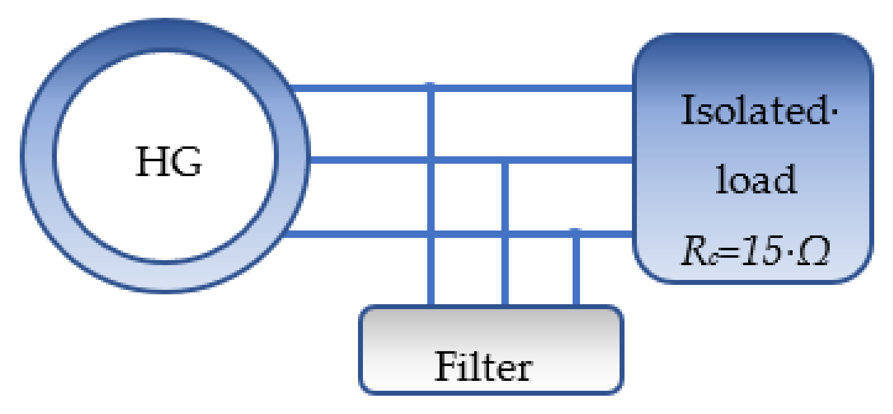
Passive filters consist of various elements, including capacitance, inductance, and resistance, and are primarily designed to reduce or eliminate harmonic distortion. The installation of a low-pass filter helps filter out the high-frequency components of the electrical supply. In most cases, shunt filters are used because they can be connected parallel to the loads and do not interfere with their operation, as shown in Figure 15 [22].
Figure 15.
Passive harmonic filtering.
This filter’s cutoff frequency is set at the maximum operating frequency fmax (7).
With Ωgm = 239 rd/s: operating speed in zone III.
In the end, the filter is expressed as:
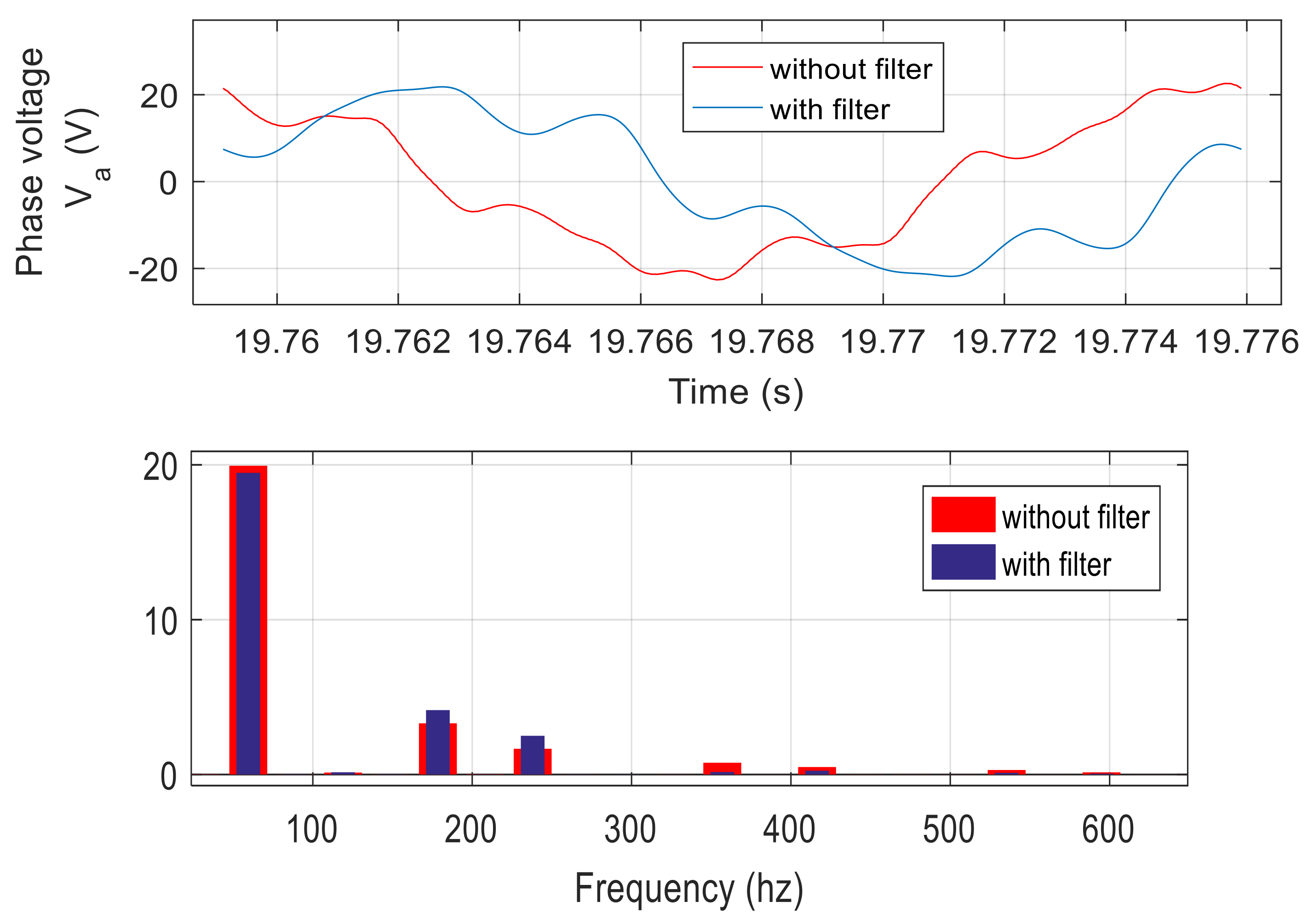
We begin by testing the filter at high speed (vw =13.5 m/s). Figure 16 displays the waveform of the stator voltage and its FFT analysis. The total harmonic distortion and harmonic rates 3, 4, and 6 are significantly reduced (Table 5), but the filter still does not meet the standards set by EN 50160.
Figure 16.
Stator voltage as a function of time FFT analysis of voltage in phase “a”.
Table 5.
Harmonic analysis of stator voltages.
This filter interferes with the low-speed functioning of the wind system by adding harmonics and causing the generator to switch to low rotational speeds. Figure 17 depicts the results of an analysis performed at a starting speed of vw = Vd = 3 m/s. It is shown that the addition of the low-pass filter increases the overall THD from 16.58% without the filter to 21.34%, making this solution unsuitable for the autonomous operation of the wind generator.
Figure 17.
Stator voltage as a function of time and its FFT analysis.
After deployment, these filters are inflexible and cannot accommodate changes in the system, which can be problematic. Any adjustments to the assigned amount or frequency are not possible, and a shift in the system’s operating conditions can lead to significant current peaks, harmonic resonance, and other phenomena.
3.2.2. Electromagnetic Torque Control
The problem of reducing electromagnetic torque ripples of a hybrid excitation synchronous generator was first addressed in [25]. The main idea proposed in the paper is to control the excitation current at a specific operating point to reduce torque ripple. The theoretical approach involves finding the appropriate excitation current to adjust the torque at specific points over its period of variation for low rotational speeds.
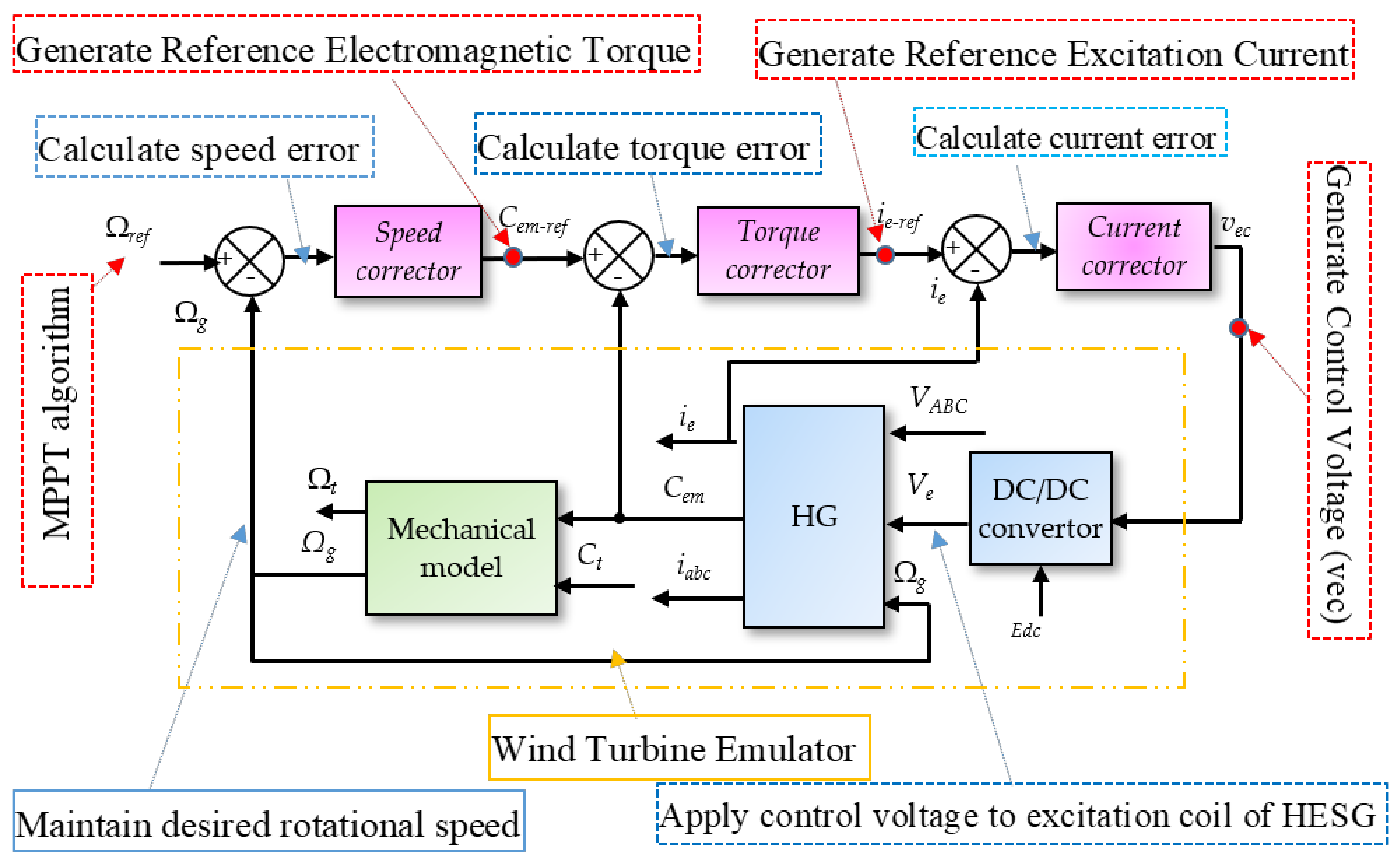
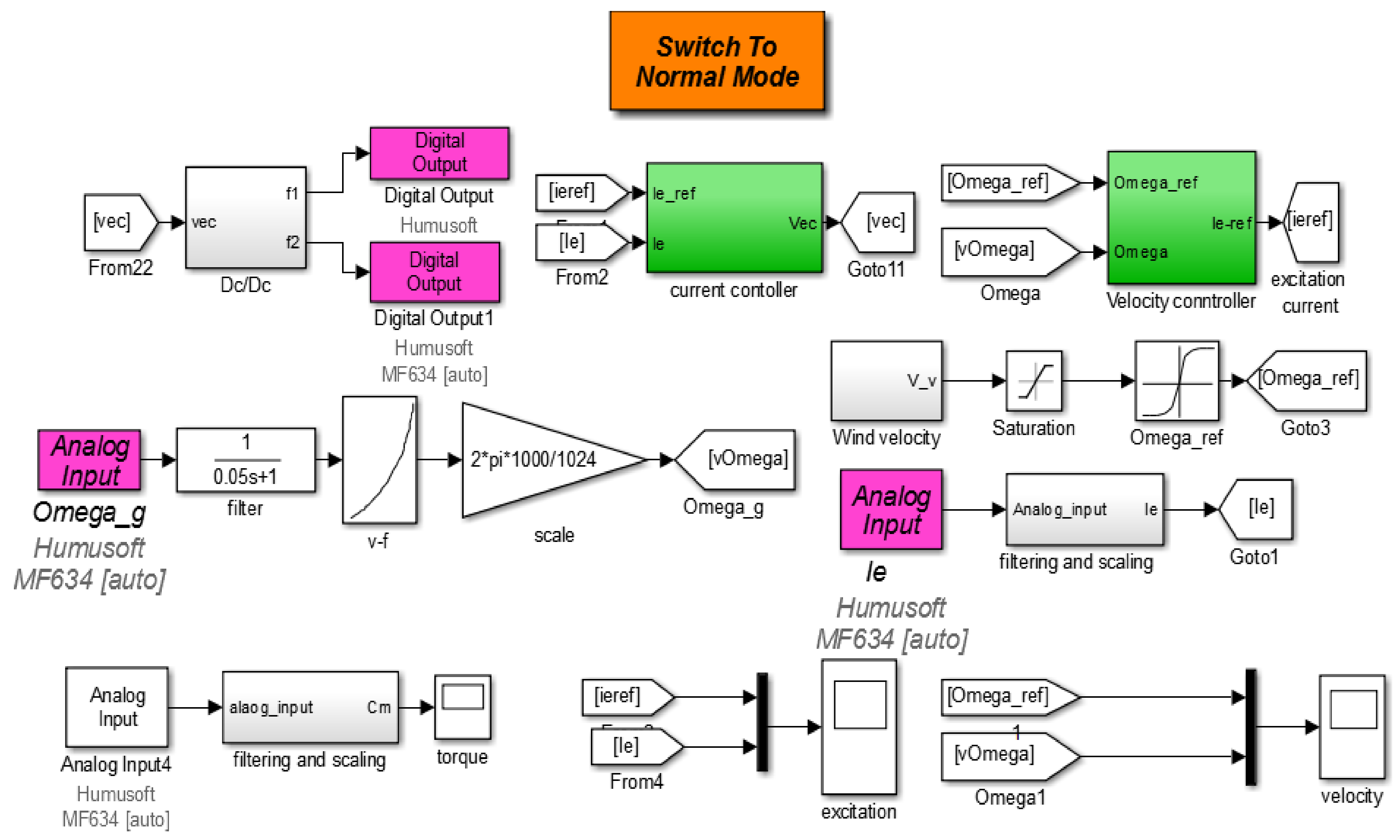
One of the novelties of our work is the implementation of a robust controller capable of minimizing the electromagnetic torque ripple through excitation current at all operating points. The control structure hierarchy is as follows: a current corrector, K′i (s), receives the error between ieref and ie, to generate the control voltage, vec. The torque corrector, KCem (s), generates the reference excitation current by receiving the difference between the Cem and the reference electromagnetic torque. The reference electromagnetic torque is derived from the cruise control system, denoted as K′Ω (s) Figure 18.
Figure 18.
Bloc diagram of the system’s Closed Loop.
The electromagnetic torque is subject to rapid oscillations. To reduce these oscillations through manipulation of ie, this current must have a dynamic that can overcome them. If this is practically feasible, the response time of the current corrector can is 0.01 ms. It should be noted that the purpose of this paragraph is only to test the feasibility of minimizing the electromagnetic torque ripples by adjusting ie.
- Current loop
- Torque loop
The electromagnetic torque is written in the reference frame d-q in the form:
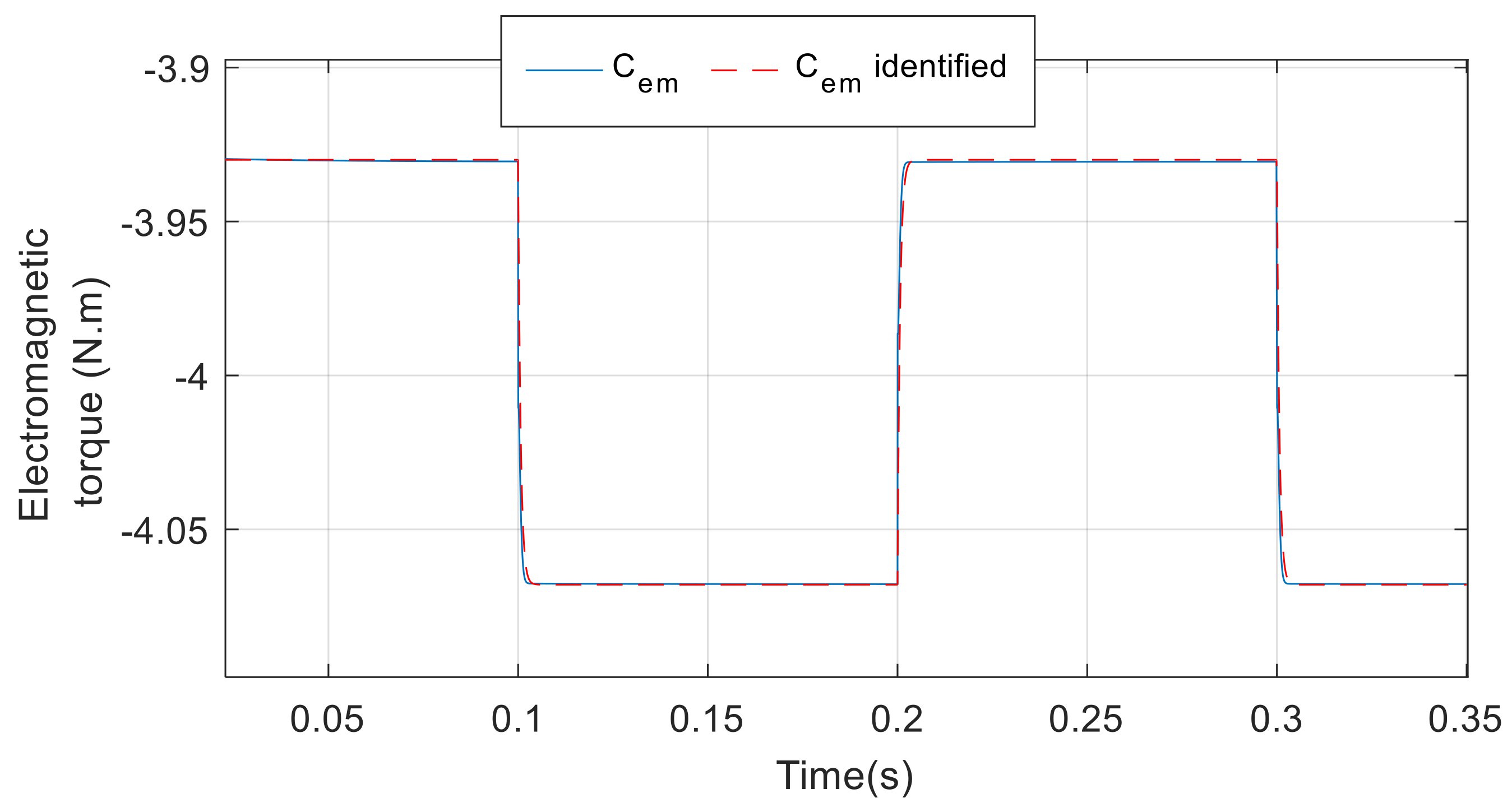
Given the non-linearity of the relation (10), Ccem = f (ieref) is established on the model without harmonics and commutations and an average model is chosen for a rotational speed of 150 rd/s (Figure 19). Its transfer function (TF) is given by (11):
Figure 19.
Identification of the function Cem = f (ie).
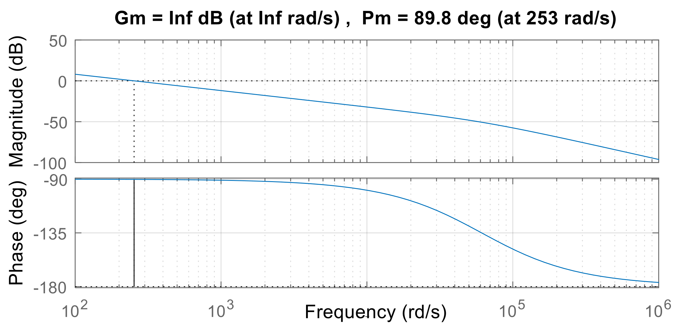
An H∞ controller is designed for this loop. The optimal response time for the torque loop is 1 millisecond (ms), which implies that its frequency should be lower than that of the current loop (which is indeed the case). Additionally, the speed loop is designed to be ten times faster than the outermost speed loop to enhance the effectiveness of the torque loop. Consequently, we can lower the requirements of the torque loop to a bandwidth of 253 rd/s.
This work uses the Normalized Coprime Factors (NCF) robust stabilization problem H∞ control theory [26]. The nominal plant’s normalized left coprime factorization is given in (12) where Y(s) and Z(s) are stable TFs.
The NCF technique produces a controller that stabilizes the nominal plant as well as any model subject to additive uncertainty on and and belongs to the perturbed plant set (13)
is reflects the greatest quantity or magnitude of uncertainty that can withstand without becoming unstable.
The goal is to solve the following equation to identify a regulator (s) that stabilizes all plants, where σmax indicates the largest stability margin.
The selected pre-compensator W1c(s) is a PIF controller with a gain that can be adjusted for a 253 rd/s bandwidth. Since Equation (11) does not include an integrator, the high gain at low frequencies is ensured by the integral action. After being configured, W1c(s) is represented by Equation (15), and the final controller, computed by the MATLAB ncfsyn function, is shown in Equation (16). The pre-compensator role is to adjust the open-loop shape.
A maximum stability margin of 0.7 and a phase margin of 89.8° (Figure 20) are obtained, which is satisfactory in terms of robustness of the closed-loop system.
Figure 20.
Bode diagram of the controlled open loop Ccem (s). KCem (s).
- Speed loop
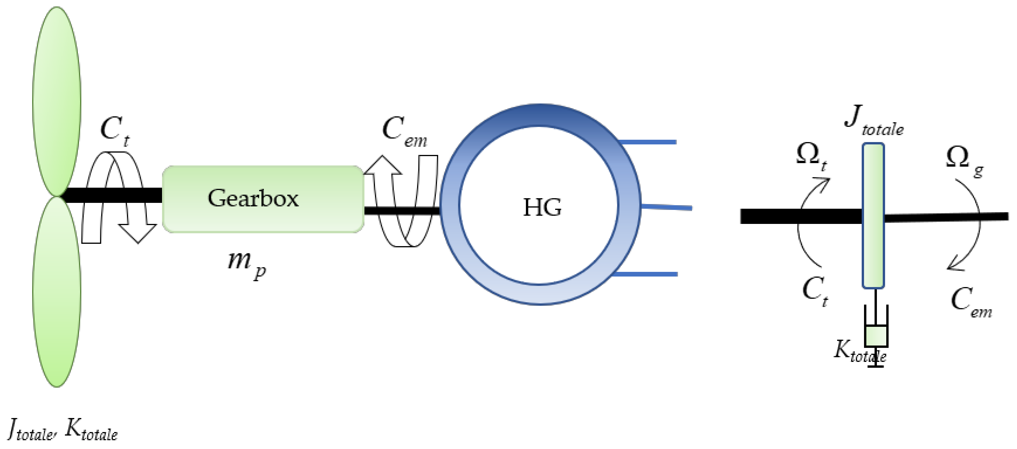
This loop was synthesized by considering a transmission chain model with a single mass, considering the complete power train, and a single friction coefficient grouping together all the friction of the rotating parts of the system. In this model (Figure 21), both the fast and slow shafts are perfectly rigid. Indeed, since the three blades are assumed to be identical, they are combined into a single mass. The inertia of the generator and gearbox can be neglected in front of the inertia of the blades and hub as a first approximation since they generally represent no more than 10% of the turbine’s total inertia: 6% to 8% for the generator and 2% to 4% for the gearbox. Alternatively, we can transfer the inertia Jg and friction Kg of the generator to the slow shaft side. In this case, we have:
The fundamental relation of dynamics applied to Jtotale implies:
The resistive torque Crt is in Equation (20).
Figure 21.
One mass mechanical model.
For single-mass modelling of the mechanical part of the turbine, the block diagram is as shown in Figure 22.
Figure 22.
Wind turbine block diagram: one-mass model.
The turbine’s torque is an undesirable fluctuation. The control transfer function is in (21):
The speed loop is based on a PI controller. The desired response time is 6 s, and its bandwidth is set at 7.28 rd/s. The corrector is given by (22):
The Bode diagram of the corrected velocity open loop is shown in Figure 23. A satisfactory phase margin of 90° is obtained around the bandwidth.
Figure 23.
Bode diagram of the corrected velocity open loop H (s) KΩ′(s).
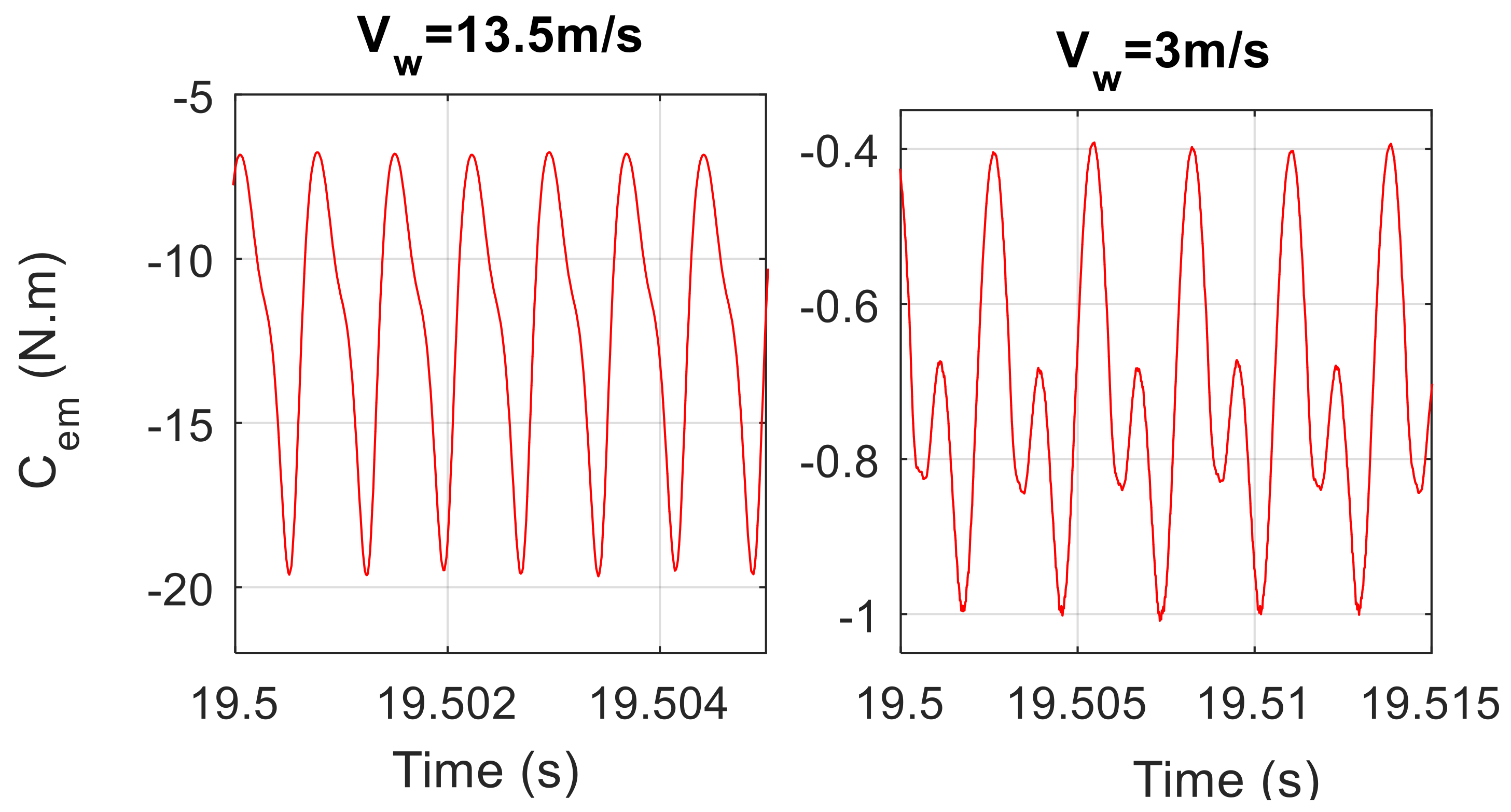
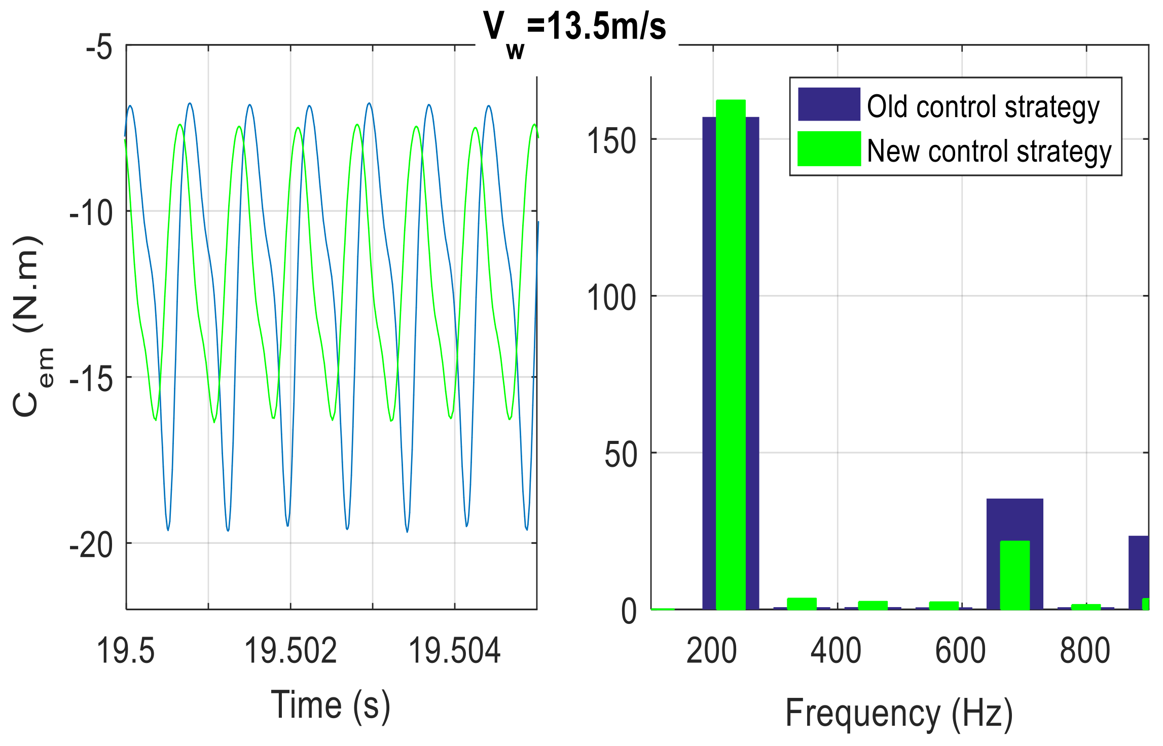
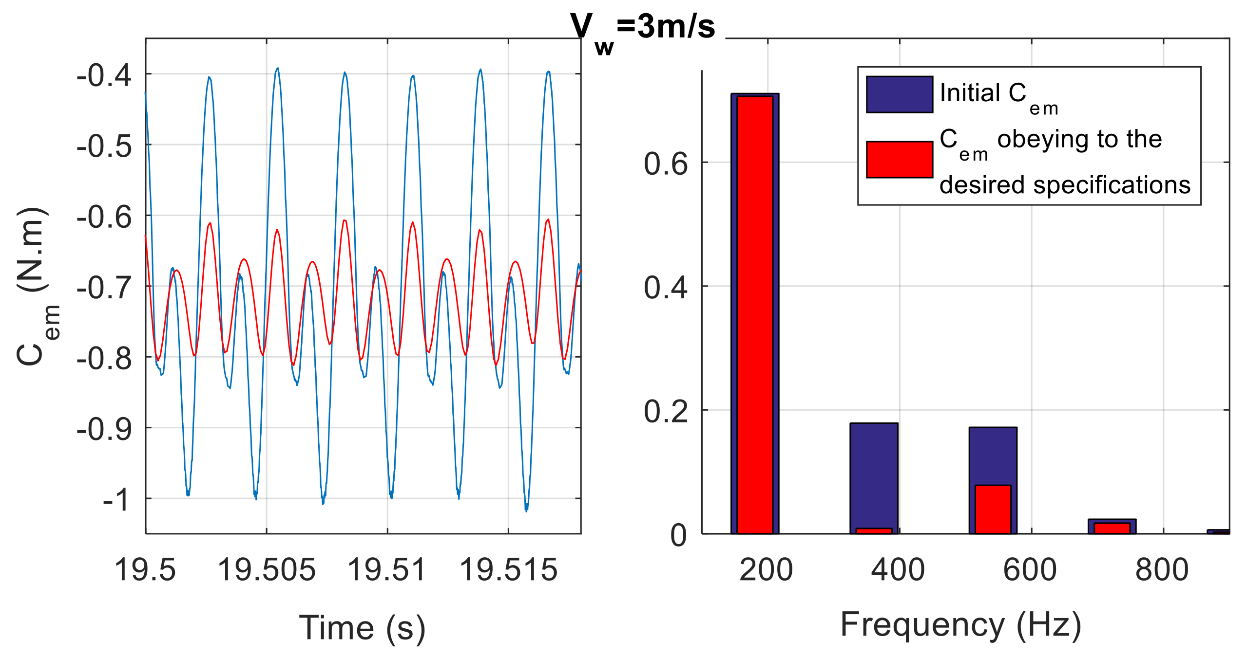
The newly implemented strategy (Figure 18) enables the reduction of the electromagnetic torque ripple. For a wind speed of 3 m/s, which corresponds to the lowest operating speed, the FFT analysis of Cem reveals a decrease in its THD by 31.27% to 29.8% (Figure 24). However, subharmonics of rank 1.5 and 2.5 appeared for vw = 13.5 m/s, corresponding to the highest operating speed (Figure 25). The rank 3 harmonic is higher with the new control strategy, but the THD is reduced from 47.15% to 36.3%.
Figure 24.
Comparison of the Cem with the two control methods (vw = 3 m/s). (legend: blue old control strategy, green: new control strategy).
Figure 25.
Comparison of the Cem with the two control methods (vw = 13.5 m/s). (legend: blue old control strategy, green: new control strategy).
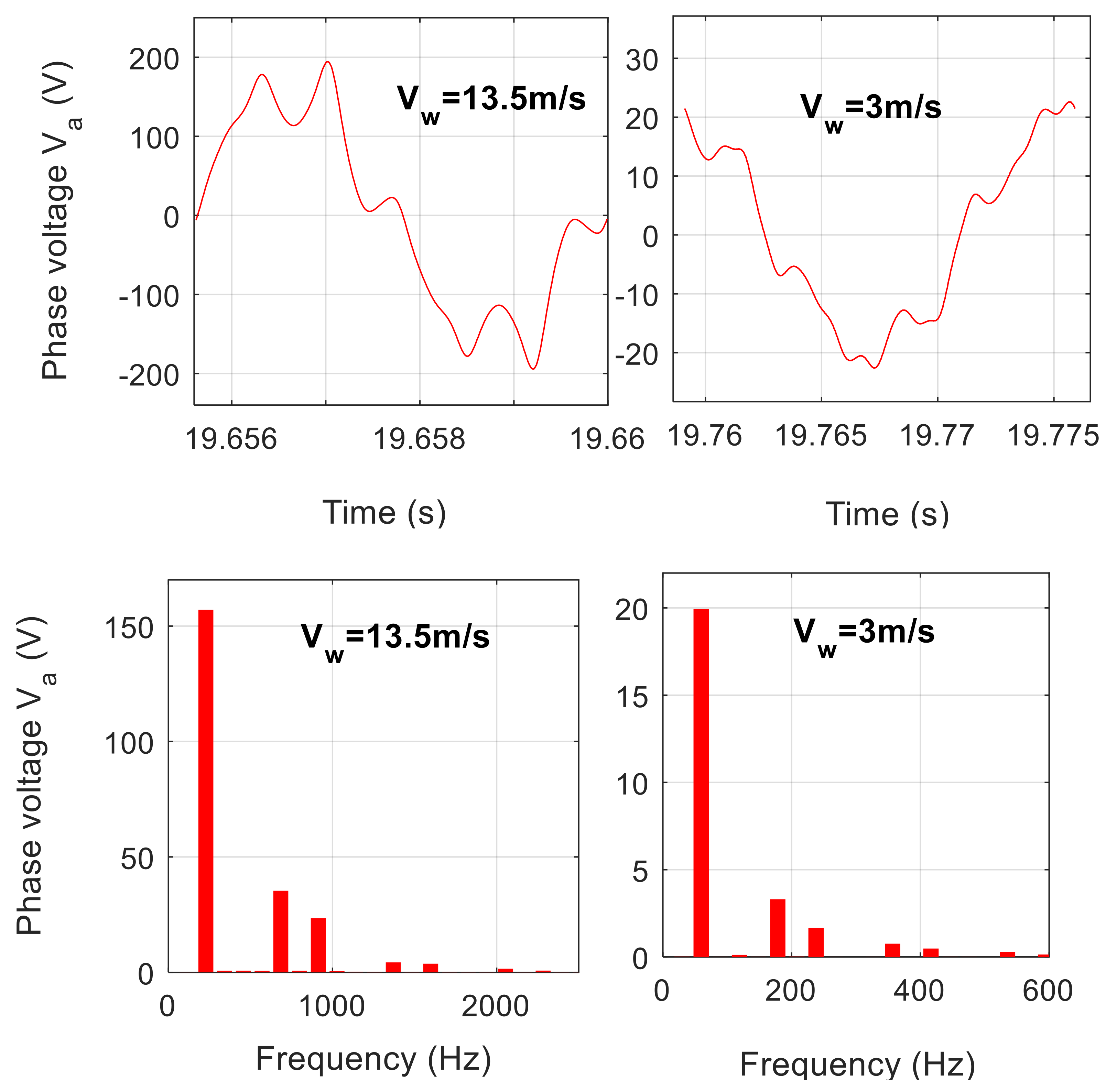
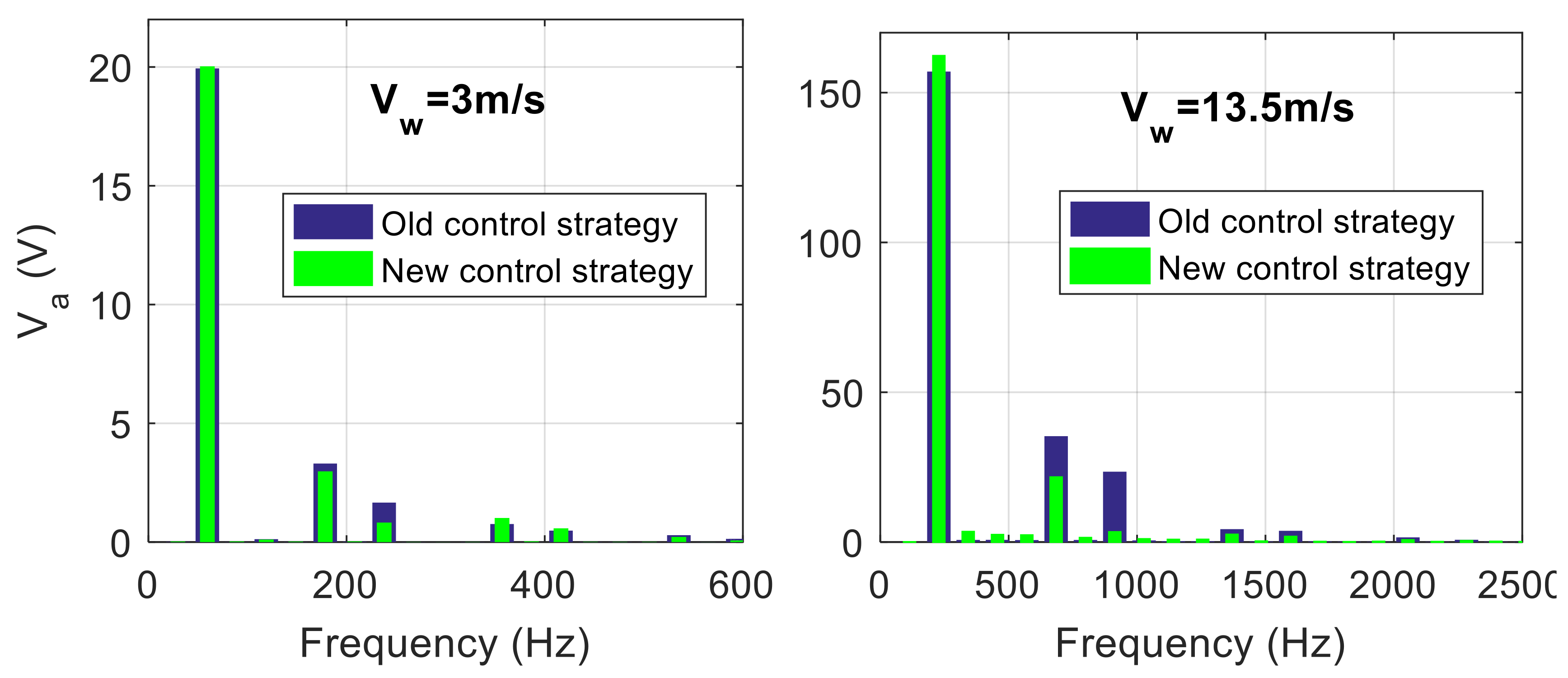
At high speeds, the overall THD is reduced from 27.32% to 14.04%, and at low speeds, from 19.18% to 16.54%, as shown by the FFT analysis of the stator voltages (Figure 26). Despite this improvement, the proposed solution is still not sufficient to comply with the specifications of EN 50160 [20].
Figure 26.
FFT analysis of voltage in phase “a”.
3.3. Limitations and Proposed Specifications
The generator architecture, as presented in [12] and implemented here, was originally developed for use in motor convention in automobile traction. This may be the reason why there are so many harmonics in this design. We need to limit the magnitude of the harmonics produced by the inductances and the excitation fluxes. An optimized structure that meets the specified requirements could be explored as a potential future direction for this research. The first step is to assess the impact of the inductances as:
The goal is to find the acceptable amplitude for Ls4 to meet the requirements outlined in Table 4. Once this value is determined, the same analysis is performed for stator mutual inductances. Harmonic 4 is included in Equation (23):
The 3rd harmonic is added to the expression of the excitation flow. Similarly, the maximum amplitude of the excitation flow is chosen to comply with the tolerable amplitudes of voltage harmonics defined by EN 50160.
This test is repeated up to harmonic 18:
Table 6 summarizes the results achieved.
Table 6.
Proposed specifications.
By meeting these specifications and at high rotational speeds, the total THD of stator voltages decreases from 27.37% to 4%, and at low speeds, from 19.18% to 4.01% (Figure 27). Figure 28 and Figure 29 illustrate the FFT analysis of the electromagnetic torque at high and low rotational speeds, respectively. Following the guidelines outlined in Table 6 significantly reduces the ripple of the electromagnetic torque. The total harmonic distortion (THD) of torque is below 11.73% at low rotational speeds and 10.2% at high speeds.
Figure 27.
FFT analysis of voltage in phase “a”.
Figure 28.
Shape of electromagnetic torque and its FFT analysis for vw = 3 m/s.
Figure 29.
Shape of electromagnetic torque and its FFT analysis for vw = 13.5 m/s.
4. Conclusions
This research proposes a thorough strategy for developing a WECS test bench based on a HESG. The qualitative and quantitative analysis of the HESG’s space harmonics and the evaluation of magnetic noise suppression measures give crucial insights into minimizing the harmful impacts of wind turbines on power grid stability and dependability. One of the most significant contributions of this study is the development of a robust controller capable of minimizing electromagnetic torque ripple via excitation current at all operating conditions. The highest permissible magnitude of the harmonics produced by the inductances and the excitation fluxes for this type of generator is a useful reference for building wind turbines with acceptable harmonic amplitude ranges.
In conclusion, the emphasis on HESG technology in WECSs and the innovative approach of a robust controller capable of minimizing electromagnetic torque ripple shows the potential for substantial advances in renewable energy. Wind turbines based on HESG technology can play a significant part in reaching a more sustainable future with more research and development.
Author Contributions
A.M.: Conceptualization, writing, experimental and simulation investigation; O.N.: Supervision; M.R.: Methodology; L.M.: Writing revision; A.B.M.: Analysis. All authors have read and agreed to the published version of the manuscript.
Funding
Research is funded by Deputyship for Research and Innovation, “Ministry of Education” in Saudi Arabia (IFKSUOR3-312-2).
Data Availability Statement
The data that support the findings of this research are available within this article.
Acknowledgments
The authors extend their appreciation to the Deputyship for Research and Innovation, “Ministry of Education” in Saudi Arabia for funding this research (IFKSUOR3-312-2).
Conflicts of Interest
The authors declare no conflict of interest.
Nomenclature
| Turbine | |
| Rp | Radius of a turbine blade (m) |
| S | Area swept by turbine blades (m2) |
| Cp | Power coefficient of the wind turbine |
| λ | Tip speed ratio |
| β | Pitch angle |
| Transmission shaft | |
| Kt | Viscous coefficient of rotor friction |
| Jt | Turbine rotor inertia |
| Kg | Viscous coefficient of friction of the generator |
| Jg | Inertia of the hybrid generator |
| Ktotale | Viscous coefficient of friction of the wind system |
| Jtotale | Total inertia of rotating parts |
| mp | Multiplier coefficient |
| Kls | Depreciation coefficient |
| Dls | Torsion coefficient |
| Ct | Turbine torque |
| Crt | Resistive torque |
| Cem | Electromagnetic torque |
| Cls | Torsion torque (slow shaft side torque) |
| Ωt | Slow axis speed (turbine speed) |
| Ωg | Fast axis speed (generator speed) |
| θt | Slow axis angle (turbine position) |
| θg | Fast axis angle (generator position) |
| Hybrid generator | |
| Ie | Excitation current |
| [ϕ] | Stator flux vector |
| [I] | Stator current vector |
| [V] | Stator voltage vector |
| [ϕe3] | Excitation flux produced by magnets in stator coils |
| [Me] | Vector of stator-excitation mutuals |
| Le | Excitation inductance |
| [L] | Stator inductor matrix |
| Rs | Armature resistance |
| Re | Excitation coil resistance |
| φa | Flux created by magnets on a stator winding |
| φae | Flux created by magnets on an excitation winding |
| Ls | Cyclic stator inductance |
| w | Electrical pulsation |
| σ | Blondel Coefficient |
| p | Number of pole pairs |
| Ld | D-axis armature inductance |
| Lq | q-axis armature inductance |
| M | Mutual inductance between the inductor and the armature in the coordinate system d,q |
Appendix A
Table A1.
Electrical and mechanical parameters of the WECS 3 kW.
Table A1.
Electrical and mechanical parameters of the WECS 3 kW.
| Parameter | Value (Uncertainty Range) | Parameter | Value (Uncertainty Ranges) |
|---|---|---|---|
| Kt (kg.m2 s−1) | 0.055 (±75%) | Me (mH) | 1.1 (80–100%) |
| Jt (kg.m2) | 3.6 | Ld (mH) | 5 (50–100%) |
| Dls | 0.8 (±25%) | Lq (mH) | 9.2 (50–100%) |
| Kls | 160(+48%/−34%) | Le (mH) | 46 (50–100%) |
| Jg (kg.m2) | 0.015 | Re (Ω) | 3 (100–150%) |
| ɸa (mWb) | 66 (80–100%) | Rs (Ω) | 0.87 (100–150%) |
References
- Liu, X.; Feng, L.; Kong, X. A Comparative Study of Robust MPC and Stochastic MPC of Wind Power Generation System. Energies 2022, 15, 4814. [Google Scholar] [CrossRef]
- Shiravani, F.; Cortajarena, J.A.; Alkorta, P.; Barambones, O. Generalized Predictive Control Scheme for a Wind Turbine System. Sustainability 2022, 14, 8865. [Google Scholar] [CrossRef]
- Merabet, A. Adaptive Sliding Mode Speed Control for Wind Energy Experimental System. Energies 2018, 11, 2238. [Google Scholar] [CrossRef]
- Qin, S.; Chang, Y.; Xie, Z.; Li, S. Improved Virtual Inertia of PMSG-Based Wind Turbines Based on Multi-Objective Model-Predictive Control. Energies 2021, 14, 3612. [Google Scholar] [CrossRef]
- Eial Awwad, A. Dynamic Performance Enhancement of a Direct-Driven PMSG-Based Wind Turbine Using a 12-Sectors DTC. World Electr. Veh. J. 2022, 13, 123. [Google Scholar] [CrossRef]
- Kalel, D.; Subramaniam, U.; Hunachal, S. Torque Ripple Reduction in PMSG for Standalone Wind Energy System Using Three Level DTC with A Dither Signal. In IOP Conference Series: Materials Science and Engineering; IOP Publishing: Bristol, UK, 2020; Volume 937. [Google Scholar]
- Mahmoud, M.S.; Oyedeji, M.O. Adaptive and Predictive Control Strategies for Wind Turbine Systems: A Survey. IEEE/CAA J. Autom. Sin. 2019, 6, 364–378. [Google Scholar] [CrossRef]
- Mseddi, A.; Le Ballois, S.; Aloui, H.; Vido, L. Robust control of a wind conversion system based on a hybrid excitation synchronous generator: A comparison between H∞ and CRONE controllers. Math. Comput. Simul. 2019, 158, 453–476. [Google Scholar] [CrossRef]
- Mseddi, A.; Le Ballois, S.; Aloui, H.; Vido, L. Comparative study of two robust control strategies for a wind conversion system based on a hybrid excitation synchronous generator. In Proceedings of the Electrimacs, Toulouse, France, 4–6 July 2017. [Google Scholar]
- Cisneros-Magaña, R.; Medina-Rios, A.; Fuerte-Esquivel, C.R.; Segundo-Ramírez, J. Harmonic state estimation based on discrete exponential expansion, singular value decomposition and a variable measurement model. Energy 2022, 249, 123712. [Google Scholar] [CrossRef]
- Jain, S.K.; Singh, S.N. Harmonics estimation in emerging power system: Key issues and challenges. Electr. Power Syst. Res. 2011, 81, 1754–1766. [Google Scholar] [CrossRef]
- Vido, L. Study of Electric Actuators with Double Excitation Intended for Transport: Dimensioning of Synchronous Structures. Ph.D. Thesis, ENS Cachan, Gif-sur-Yvette, France, 2004. [Google Scholar]
- Available online: https://www.humusoft.cz/datacq/mf624/ (accessed on 15 December 2022).
- Available online: https://www.heidenhain.fr/fileadmin/pdb/media/img/349529-39_Capteurs_rotatifs_fr.pdf (accessed on 5 December 2022).
- Available online: https://www.astuces-pratiques.fr/electronique/convertisseur-frequence-voltage-passif-simple (accessed on 16 November 2022).
- Srikanth, N.; Fun, J.L. Geometric scaling and long-run reductions in cost: The case of wind turbines. In Proceedings of the IEEE First International Technology Management Conference, San Jose, CA, USA, 27–30 June 2011; pp. 691–696. [Google Scholar]
- Chaviaropoulos, P.K. Similarity Rules for W/T Up-Scaling. In Proceedings of the CRES, April 2006. Available online: https://www.studeersnel.nl/nl/document/technische-universiteit-delft/wind-turbine-design/similarity-rules-for-wt-upscaling-2007/13331510 (accessed on 2 June 2023).
- Khezami, N. Optimal Multi-Model Control of Wind Turbines: Application to the Participation of Wind Turbines in Frequency Adjustment. Ph.D. Thesis, Ecole Centrale de Lille-France and Ecole Supérieures des Sciences et Techniques, Tunis, Tunisia, 2011. [Google Scholar]
- Teninge, A. Participation in Mixed Wind Farm System Services: Application in Island Environments. Ph.D. Thesis, Polytechnic Institute of Gronoble, Grenoble, France, 2009. [Google Scholar]
- Leithead, W.E.; Connor, B. Control of variable speed wind turbines: Dynamic models. Int. J. Control 2011, 73, 1173–1188. [Google Scholar] [CrossRef]
- Calvas, R. Technical Report n° 141: Electrical Disturbances in BT. Schneider Electric, May 2001. Available online: http://www2.schneider-electric.com/documents/technical-publications/fr/shared/electrotechnique/savoir-electrotechnique/basse-voltage-moins-1kv/ct141.pdf (accessed on 14 July 2017).
- Singh, B.; Chandra, A.; al-Haddad, K. Power Quality Problems and Mitigation Techniques; John Wiley and Sons Ltd.: Hoboken, NJ, USA, 2015. [Google Scholar]
- Nasr, A. Harmonics Analysis of a Wind Energy Conversion System with a Permanent Magnet Synchronous Generator. Master’s Thesis, Dalhousie University Halifax, Halifax, NS, Canada, 2015. [Google Scholar]
- Bjork-Svensson, J.; Pascual, J.M. Torque Control of a Wind Turbine Using 6-Phase Synchronous Generator and a dc/dc Converter. Ph.D. Thesis, Chalmers University of Technology, Göteborg, Sweden, 2007. [Google Scholar]
- Hoang, K.; Vido, L.; Gabsi, M.; Gillon, F. Flux Control Range Broadening and Torque Ripple Minimization of a Double Excitation Synchronous Motor. IEEE Trans. Magn. 2017, 53, 8100510. [Google Scholar] [CrossRef]
- McFarlane, D.C.; Glover, K. Robust Controller Design Using Normalized Coprime Factor Plant Descriptions; Lecture Notes in Control and Information Sciences; Springer: Berlin/Heidelberg, Germany, 1990. [Google Scholar]
Disclaimer/Publisher’s Note: The statements, opinions and data contained in all publications are solely those of the individual author(s) and contributor(s) and not of MDPI and/or the editor(s). MDPI and/or the editor(s) disclaim responsibility for any injury to people or property resulting from any ideas, methods, instructions or products referred to in the content. |
© 2023 by the authors. Licensee MDPI, Basel, Switzerland. This article is an open access article distributed under the terms and conditions of the Creative Commons Attribution (CC BY) license (https://creativecommons.org/licenses/by/4.0/).