Abstract
Recently, the advanced driver assistance system (ADAS) of autonomous vehicles (AVs) has offered substantial benefits to drivers. Improvement of passenger safety is one of the key factors for evolving AVs. An automated system provided by the ADAS in autonomous vehicles is a salient feature for passenger safety in modern vehicles. With an increasing number of electronic control units and a combination of multiple sensors, there are now sufficient computing aptitudes in the car to support ADAS deployment. An ADAS is composed of various sensors: radio detection and ranging (RADAR), cameras, ultrasonic sensors, and LiDAR. However, continual use of multiple sensors and actuators of the ADAS can lead to failure of AV sensors. Thus, prognostic health management (PHM) of ADAS is important for smooth and continuous operation of AVs. The PHM of AVs has recently been introduced and is still progressing. There is a lack of surveys available related to sensor-based PHM of AVs in the literature. Therefore, the objective of the current study was to identify sensor-based PHM, emphasizing different fault identification and isolation (FDI) techniques with challenges and gaps existing in this field.
Keywords:
autonomous vehicle; prognostic health management; sensor-based fault detection; data-driven approaches; perception sensors MSC:
68T01
1. Introduction
Recently, automation in the automobile industry has been evolving with significant development. Autonomous vehicles (AVs) with advanced driver assistance systems (ADASs) provide significant benefits to drivers, while also providing new transportation use scenarios and implementations [1]. Localization, perception, planning, vehicle control, and system management are the five fundamental capabilities for AVs to drive without human involvement. The ADAS system of AVs is the electronic system that executes the driving operations [2]. The automation offered by ADAS to AVs is a significant feature for the safety of the modern vehicle. The demand for the ADAS system is increasing daily, because of its intelligent safety development toward customer requirements [3]. Over the years, various researchers have identified safety-related issues in AV technology [4]. For example, Yu and Biswas [5] proposed a unique dedicated short-range communication (DSRC)-based medium access control (MAC) framework for intervehicle communication (IVC). Furthermore, the distributed power control method is suggested to control a load of periodic messages on the channel [6]. Bi et al. [7] introduced a cross-layer broadcast protocol for efficient and dependable message delivery in IVC systems. Palazzi et al. [8] proposed an innovative IVC framework that adjusts its features and functionality to deliver implementations efficiently. Tabatabaei et al. [9] improved simpler network topologies for simulation models by enhancing ray-tracing-derived wireless propagation models.
The ADAS is composed of various sensors. The primary purpose of these sensors is to improve the safety of passengers and the vehicle itself, which is the primary justification for developing AVs [10]. The AV localization consists of different sensors: vision sensors (cameras), LiDAR, RADAR, ultrasonic sensors, GPS/GNN, etc. [11,12]. These sensors of the ADAS system can be affected by various malfunctions that lead to the failure of these components. For instance, camera quality can be affected by multiple factors, such as lens occlusion or soiling, environmental and weather conditions, optical faults, and visibility distance [13]. Similarly, LiDAR failure occurs due to read position data, short-circuit and overvoltage, misalignment of the optical receiver, and fault in the optical filter mirror motor [14]. In addition, various reasons have been listed that have led to RADAR failures, such as cyberattack [15] and environmental conditions [16]. Ultrasonic sensor performance can be degraded via vehicle corner error [16], temperature variation and relative humidity [17], false echoes caused by turbulence [18], and acoustic or electric noise [19]. Faults in GPS/GNN occur due to anomalies in different segments of the positioning sensors, i.e., receiver malfunction in the user segment, clock anomalies in the space segment, and satellite broadcast anomalies due to the control segment [20].
Sensor-based PHM in AV technology is indeed evolving, and different studies worldwide are proposing their ideas. Recently, different researchers have proposed various PHM strategies employing sensor-based fault detection. Mori et al. [21] presented a Kalman filter-based FDI for various sensors, including camera sensors. Tadjine et al. [22] proposed a self-diagnosis approach for a camera-based ADAS system to identify and assess these visual warnings. Duran et al. [14] enlisted various kinds of faults in the LiDAR system, along with the severity level of fault occurrence in any particular component of the LiDAR system. In addition, signal processing challenges were described for the RADAR in AVs to justify the updated integration and technology trends [23]. Park et al. [24] proposed a multi-sliding mode observer for the fault detection of the sensor to ensure the longitudinal control of the AVs. Similarly, Oh and Yi [25] proposed a sliding mode algorithm for the fault detection of AV sensors. Lyu et al. [26] proposed fault prediction based on reliability data, prediction parameter monitoring, cumulative damage model, and early warning in a RADAR system as a function of the system’s physical characteristics. Lim et al. [27] highlighted some of the undesirable situations of ultrasonic sensors. The transducer of the ultrasonic sensor was modified to minimize the width of the beam [28]. The multiple echo signal processing method was applied to reduce vehicle corner error [16]. In addition, Changle Li et al. [29] classified GPS errors into three main categories: GPS satellites, signal propagation, and error at the end of the receiver.
This paper provides comprehensive insight into the development and future research possibilities of sensor-based PHM systems in AV technology. PHM for AV technology is still evolving with multiple research scopes. However, grasping the overall shape of technology and its trajectory is extremely difficult. The majority of studies defined problems in a very narrow range, with several limitations. However, this is the very first attempt to review the overall sensor-based PHM for AVs. AVs are composed of different sensors such as RADAR, cameras, ultrasonic sensors, and LiDAR. The impacts of sensor malfunctioning and sensor uncertainty on the PHM are described. In the present paper, the abovementioned sensors are summarized in detail along with the fault-detection approaches associated with ADAS. Furthermore, the issues associated with the PHM of AVs are highlighted. This paper also covers the safety concerns of AV technology and future industry trends for further developments. This review is divided into three different sections. Section 2 provides an overview of PHM, AVs, and faults associated with sensors. In Section 3, different PHM approaches for different sensors of ADAS for AVS are discussed. Section 4 summarizes the limitations/challenges in the field of AVs and sensor-based PHM for AVs.
2. Overview of PHM, ADAS in AVs, and Sensor Faults
2.1. Overview of PHM Technology
PHM was used for the first time in the 1990s during the Joint Strike Fighter (JSF) project by the US army. PHM provides tangible tools to facilitate carrying out necessary decisions in a timely manner. The PHM cycle is composed of eight steps as shown in Figure 1 and Table 1. Initially, a physical sensor is used to sense soft system performance attributes in the form of a variable of the system. Afterward, sensor data are collected from the system using a data acquisition system such as an internal monitor, data bus, or PC. In the data manipulation state, the data preprocessing techniques can be acquired. In the state of detection, whether the system is normal or abnormal can be proposed on the basis of system condition indicators. In the health assessment state, a set of information can be presented to acquire the state of health (SOH) of the system. The prognostic assessment gives future SOH and remaining useful life (RUL) prediction [30,31]. The advisory generation function gives applicability to operate and repair the system. The final stage of health management uses information for advisory generation when the system is unable to operate normally (healthy state). Prognostic assessment is considered the most critical step in the PHM process where the RUL of the system can be predicted on the basis of available data and current operational condition.
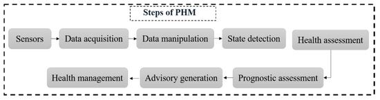
Figure 1.
Steps involved in the prognostic health management (PHM) process.
2.2. Autonomous Vehicle and Advanced Driver Assistance System
Recently, autonomous vehicles have gained public interest due to their potential for enhancing road traffic productivity and capability. The advanced driver assistance system (ADAS) is the electronic system that controls driving and parking operations [32]. The automated system provided by ADAS to autonomous vehicles is a prominent characteristic for protecting the modern automobile. The safety systems are categorized into two classes of passive and active. Passive safety systems protect vehicle occupants from injuries during and after a crash, e.g., airbags, padded dashboards, and seat belts. At the same time, the active system includes various features, such as lane keeping, automatic braking, and adaptive cruise control [33]. Due to the growing client demand for smart safety systems, some of the critical purposes for manufacturers involve developing the ADAS. Moreover, with the increasing number of electronic control units and the combination of multiple sensors, there are now sufficient computing aptitudes in the car to support ADAS deployments. Various sensors enable various ADAS solutions, such as RADAR, cameras, ultrasonic sensors, and LiDAR. The vision-based ADAS, which principally manages cameras as vision sensors, is prevalent in the modern automobile [34]. Figure 2 shows the locations of various sensors in AVs. Figure 3 shows the proposed taxonomy of the ADAS based on the model of sensors used. The vision system is composed of various cameras such as monocular, stereo, and infrared cameras. The RADAR can be long-, short-, or medium-range.
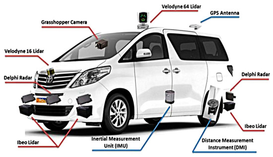
Figure 2.
Demonstrations of various sensors in an autonomous vehicle (AV) [35].
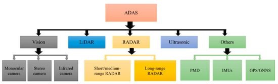
Figure 3.
Taxonomy of advanced driver assistance systems (ADASs) based on the model of sensors.
2.3. Sensor Malfunctioning in AVs
A fault is an undesirable deviation from the normal state of a system’s characteristic, property, or parameter [36,37]. The fault can be categorized into sensor, actuator, and component-level faults [38]. While the sensor fault focuses more on input module problems, the actuator faults focus on output module concerns. Furthermore, the sensor fault is categorized into hard and soft faults [39]. In hard faults, the sensor data abruptly shift from the usual situation to a faulty one; complex faults appear in stepwise format. In contrast, soft faults occur as slow degradations in the sensor output with respect to time. Soft faults are more difficult to detect and eliminate, because sensor data take time to leave a confidence limit. In addition, component or process faults occur in the complete module of the system. For the AV, the fault is usually caused because of the sensors. There are various faults in the sensors, such as a faulty transmitter or receiver, or a fault in the processing system. On the other hand, scratches, cracks, holes, and sensor covers are considered mechanical faults. A film on the sensor cover, such as water, ice, dust, snow, or salt, can prevent objects from being detected (false negatives), from being seen (false positives), or from being correctly classified [40,41]. In addition, inaccurate data injection by another active electromagnetic source leads the system to an electronic hack via a wired or wireless connection to the sensor [42]. Furthermore, when exposed to unfavorable environmental conditions, the perception sensor holds constraints that reduce the field of view. Crosstalk from other active perception sensors may cause a fault in the sensor. Figure 4 shows various faults associated with sensors [43].
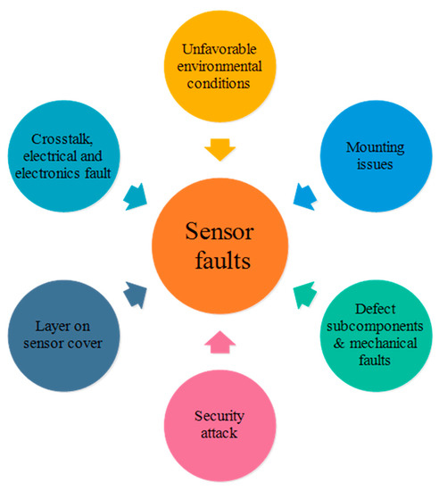
Figure 4.
Demonstration of various sensor faults.
Fault diagnosis consists of three steps: fault detection, fault isolation, and fault identification. Hence, sensor fault detection and isolation (FDI) for the localization system of autonomous vehicles is one of the most critical tasks. Localization systems consist of external sensors such as camera systems (vision), LiDAR, RADAR, ultrasonic sensor, and global navigation satellite systems, which are significantly affected by weather conditions and geographic variances [44]. Various faults, such as erratic, spike, hard-over, and stuck are examples of sensor faults [45]. Even if the sensor is fully functioning, it is critical to detect the performance degradation of various components. Hence, fault detection of the multiple sensors without prior knowledge is one of the most significant tasks for the safety of autonomous cars. Furthermore, preventive maintenance is an effective practice for reducing the sensor failure rate [46]. The next section comprehensively summarizes the PHM of ADAS sensors.
2.4. Sensors Uncertainty and PHM
PHM requires a high-performance sensor system to determine the health monitoring of the system and maintain a certain level of uncertainty. In a previous study [47], the various sources of prognostic uncertainties were investigated, and it was discovered that measurement inaccuracy by the sensor system is one of the primary sources of uncertainty in PHM applications. Recognizing the performance characteristics of different sensors can assist in identifying the degree of uncertainty induced by different sensors and in adjusting the uncertainty of the PHM implementation. Failed sensor systems generate inaccurate or incomplete data, causing PHM to generate incorrect detections and estimations. The adverse effects on PHM can be more serious if the sensor system is used to measure a vital attribute or is installed in a restricted access position. The reliability of the sensors reflects the ability of a sensor system to perform an essential role under defined conditions for a specific duration. Nevertheless, sensor system manufacturers very seldom describe reliability information such as the mean time between failures (MTBF) and failure rate under specific environmental and operating conditions. However, the reliability of the sensors can be improved by using numerous sensors (redundancy) for monitoring the same system. As a result, the probability of data loss due to sensor system uncertainty is reduced. Several other techniques, such as sensor validation, can improve sensor reliability. Sensor validation is used to evaluate the authenticity of a sensor system and adjust or correct it as needed [48]. This operation examines signal quality and ensures that the sensor system is operating properly by detecting and eliminating the impact of systematic errors. When choosing a sensor system, the client can also look at whether it includes validation capabilities [49].
3. Sensor-Based PHM for ADAS System
In this section, various kinds of ADAS sensors are introduced according to the working principles. Various faults associated with different sensors such as cameras, RADAR, ultrasonic sensors, and LiDAR are highlighted. Furthermore, various PHM techniques are described for aforementioned sensors with fault types, techniques, and consequences. Lastly, the challenges related to each sensor are mentioned.
3.1. PHM of Vision Sensors
The vision-based ADAS relies on images from the cameras and uses computer vision systems to obtain essential information. This system includes various cameras, such as monocular, stereo, and infrared cameras. Figure 5 shows the workflow of the vision system. Firstly, in image acquisition, a frame is captured from videos, consisting of pixel data and three-channel information, such as red, green, and blue (RGB) sets of pixels. Secondly, preprocessing consists of denoising, color improvement, color space transformation, and image stabilization. The features are then separated in the segmentation process that helps divide these features into various recognizable objects, such as road, footpath, crosswalk, and sky. The method of classifying an object in an image, e.g., an object ahead of a vehicle or any obstacle, can be determined in object detection. Depth estimation estimates the distance of an object relative to the camera. Lastly, the control system interprets the vision data from the previous layers.
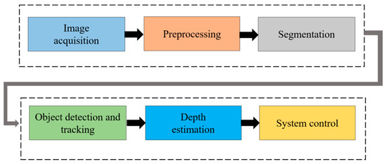
Figure 5.
Vision data flow of an advanced driver assistance system (ADAS).
Through the adoption of a camera-based ADAS system, handy opportunities have evolved to support autonomous driving systems. Figure 6 shows object detection of the camera images infused with LiDAR mapping for AV applications. The in-vehicle multipurpose cameras and exterior fish-eye parking cameras assist in extending the knowledge of drivers in several circumstances, such as identifying pedestrians, other cars, and road signs or generating a bird’s-eye view. In addition to the ability to visualize, human visual perception is constricted by visibility conditions. However, in actual scenarios, various conditions influence the degradations of camera sightedness. Camera quality can be affected by multiple factors, such as lens occlusion or soiling, environmental and weather conditions, optical faults, sensor faults, and visibility distance. Hence, these factors affect the camera performance via blocking, blurring, range reduction, or misalignment of view. Table 1 summarizes various kinds of faults and factors that influence the visual system.

Figure 6.
Object detection via camera and LiDAR infusion for an autonomous vehicle (AV) using simultaneous localization and mapping (SLAM) technique: (a) 2D object detection; (b) 3D object detection [50].

Table 1.
Demonstration of the various factors that influence the performance of cameras [51].
Table 1.
Demonstration of the various factors that influence the performance of cameras [51].
| S. No | Camera Faults | Detailed Description of Camera Malfunctioning |
|---|---|---|
| 1 | Lens occlusion or soiling | Covering of the lens by solid or fluid |
| 2 | Weather condition | Rain/snow |
| Icing of camera | ||
| Fogging of camera | ||
| 3 | Environmental condition | Time (dawn or dust) |
| Crossing by tunnel or over a bridge | ||
| Inner-city roads or motorways | ||
| 4 | Optical faults | Lens occupied by dust |
| Lens loss | ||
| Interior fogging | ||
| Damage or stone impact of the lens | ||
| 5 | Sensor faults | Smear |
| Image element defect (black or white marks) | ||
| Thermal disturbance | ||
| 6 | Visibility distance | Range of distance to detect a clear image |
Tremendous research work has been carried out to perform the FDI of AV camera sensors. For that purpose, various FDI techniques are utilized for AV sensor fault detection. Table 2 demonstrates various kinds of faults for the camera of the AV and the FDI techniques, along with the advantages of the proposed techniques. Kalman filter is one of the leading-edge techniques that can be used for FDI using multiple sensor data. Each Kalman filter is designed on the basis of a specific hypothesis for detecting a particular sensor fault. The state covariance matrix estimated from each filter can be compared for FDI analysis of sensors [52,53]. Mori et al. [21] presented a Kalman filter-based FDI for various sensors, including camera sensors. The sensor data are affected by multiple factors, such as climate, humidity, smog and fog, topography, and even network communications. In the proposed methodology, to tackle these issues, sensors filters are evaluated by Hoteling’s test to obtain the outcomes and their covariance. Hence, the FDI of the sensor is assessed by correlating the generated within the sensor. In another study, the Kalman filter and discrete wavelet transform were proposed as rain removal algorithms using the You Only Look Once (YOLOv3) methodology for the camera FDI of AVs [54]. Realpe et al. [55] proposed a sensor fusion framework that integrates data from a unified configuration with sensor weight provided in a real-time FDI using the SVM algorithm to reduce the impact of sensor faults. Although Google, GM, BMW, and Tesla are trying and testing various AVs, multiple issues, such as bugs in traditional software, are a challenging task to fix, when compared with the DNN-based software [56]. Hence, DeepTest-based algorithms are implemented to detect the erroneous behavior that leads to fatal crashes. The presented study automatically generated test cases on the basis of real-world variations in driving states, such as lighting, fog, and rain. Tadjine et al. [22] presented a self-diagnosis approach for a camera-based ADAS system that identifies and assess these visual warnings. To overcome the camera failures because of the weather conditions, such as heavy rain and snow, Sprinnker et al. [57] presented a camera-based fog detection mechanism by analyzing the power spectrum slope (PSS) of a small image frame near the vanishing point, resulting in quick differentiation of fog-free and fog-filled street scenes.
Table 2.
Demonstration of fault types and prognostic health management (PHM) analysis for an autonomous vehicle (AV) camera.
3.2. PHM of Light Detection and Ranging (LiDAR) Sensor
The LiDAR system combined with the vision system can be used as a fundamental technology for the optical system of AVs. Automotive LiDAR sensors are supposed to perform blind-spot monitoring, pedestrian identification, obstacle detection [35], and landscape mapping [59] to ensure reliability and safety during driving operations. LiDAR sensors are currently being used by various companies, such as Google [60], BMW, and Volvo [61], to develop autonomous vehicles. Figure 7 shows the application of the LiDAR sensor in a real driving environment [62]. Usually, the LiDAR unit comprises various parts: power regulator, receiver, lens filter, laser, rotating mirror, onboard processors, and position encoder. A complex aggregate of synchronizing hardware (including precision motors and position encoders) and onboard processing capabilities is used to detect motion. Despite being designed for outdoor use, advanced LiDAR systems are extremely precise, making the mechanical components and optics vulnerable to shock. It is critical to keep the device in a safe, strategic position around the vehicle at all times. LiDAR must be equipped in places with high ground clearance and few vehicle parts, to avoid possible obstruction of the field of view. To maintain the device, precautions should be taken. Device failure could be caused by foreign object impact, shock, or vibrations caused by crashes or rough terrain navigation. One of the most crucial components of the device is the LiDAR optical filter. Any damage to the filter will have a negative impact on the reliability of the measurements. To prevent or reduce effects and scratches from vegetation, the LiDAR filter should be protected with a shroud. Table 3 lists the various LiDAR subsystem fault conditions and hazards [14].
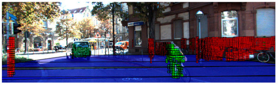
Figure 7.
Demonstration of LiDAR application in a real environment for an autonomous vehicle (AV). The mapping of various object is identified (blue color represents the plane up to a certain extent; red color represents a static object; green color indicates a moving object) [62].
Table 3.
Possible faults of light detection and ranging (LiDAR) sensor and their impact [14].
Table 4 shows the research work carried out for LiDAR technology PHM. It is divided into various categories, such as fault, FDI, and sensor recovery. The proposed drafts of fault categories and, notably, typical faults are by no means exhaustive. Nevertheless, they are intended to incorporate all significant issues that must be addressed to progress to the next level of reliable environment perception. Adverse climatic circumstances have been intensively studied for LiDAR sensors outside of our specified fault classes, primarily due to their frequency and significant influence on LiDAR perceptual theory. Faults can be categorized according to the underlying science in an alternative classification method. This could allow for standardized fault detection, isolation, and recovery techniques across fault classification. Comprehensive research work has been reviewed for fault detection, isolation, and recovery for LiDAR used as an automotive perception sensor [43]. Scattering and multiple scattering methods can be used for various faults caused by rain, smoke, snow, dust, or fog. More explicitly, the pertinent interpretation is evaluated by the particle size-to-laser wavelength relationship. The wavelength varies in the range 0.8–1.5 µm according to the laser source. Mie scattering can be applied if the particle is of a similar size to the wavelength [43]. Rayleigh scattering is to be applied when the particle is much smaller than the laser wavelength. Alternatively, non-scattering and absorption formulations are appropriate unless the particle is much larger than the wavelength, as in the case of hail. Scattering and absorption are essential not just for precipitation, but primarily for sensor protector issues. In sensor FDI, the residuals between the sensor output and various sources are correlated. In the next paragraph, various FDI techniques are presented for the LiDAR of the AV. In the recovery class, various parameters, such as software, hardware, and temperature, are adjusted according to the specification of the manufacturer.
Table 4.
Details of light detection and ranging (LiDAR) prognostic health management (PHM).
The PHM for the LiDAR of the AVs is an underdeveloped field; however, various researchers have recently been trying to develop various algorithms for the LiDAR PHM to avoid road accidents. Table 5 summarizes research work carried out for the LiDAR PHM. For example, Mori et al. [21] presented a model based on Student’s t-distribution using the Kalman filter that correlates the data within the sensor for accurate FDI analysis. Simulation and an experiment on a highway scenario confirm the robustness and accuracy of the localization and measurement noise estimation. The Velodyne LiDAR sensor allows a file containing correction factors for the alignment of the data collected by its lasers to resolve statistical anomalies (biases) in sensor readings. On the other hand, in practice, those parameters are not very specific. For example, even after applying Velodyne’s correction factors and distance offset calibrated using readings from another reference LiDAR sensor, points with uncertainties of the order of 30 cm were noted [76]. A sensor fusion design that utilizes a support vector machine (SVM) technique to integrate data from a federalized fusion framework with sensor weight feedback data provided in real-time by the fault detection and diagnosis module was used to reduce the impact of sensor faults [55]. Duran et al. [14] enlisted various kinds of faults in the LiDAR system, along with the severity level of fault occurrence in any particular component of the LiDAR system. The Bayesian belief network (BBN) algorithm was proposed to incorporate a predictive safety system.
Table 5.
Demonstration of fault types and prognostic health management (PHM) analysis for the light detection and ranging (LiDAR).
3.3. Radio Detection and Ranging (RADAR)
Radio detection and ranging (RADAR) radiates radio waves to be reflected by an obstacle, and then measures the signal runtime; it is used to approximate the object’s radial velocity with the help of the Doppler effect phenomenon. RADARs are robust against several lighting and weather conditions; however, due to the poor resolution of RADAR, it is challenging to categorize objects. RADAR sensors can operate at a number of frequencies. Nevertheless, vehicular applications appear to be standardizing on 24 and 77 GHz, with a few very-short-range sensors operating at 5.8 or 10.5 GHz [77]. They are often used in adaptive cruise control (ACC), in traffic jam assistance systems, and to assess distance and angle information about traffic objects [78,79]. The RADAR system’s operating mechanism is that it emits radio waves and collects echoes reflected off the objects.
RADAR is more economical than LiDAR and cameras, yet it can accurately estimate target range and velocity effectively. Modern RADARs both observe the target and measure distances, and they have the potential to locate, image, and identify targets [80]. As a result, the prime purpose of the RADAR in autonomous driving is the replacement of human driver vision, providing consistent, reliable information on a moving vehicle’s surroundings to enable a prompt response in constantly changing circumstances, as well as threats to and from the driven vehicle. The RADAR sensor is usually the most common in the ADAS accommodated in modern road vehicles. These systems are devised to provide different cruise control functions, as well as collision detection. These sensors can also detect the relative velocity of detected targets [81]. However, the main obstacle for the automotive RADAR system is to yield high-resolution information in an environment that incorporates several dynamic objects in an immensely clustered automotive scene with a high update rate [82,83]. Figure 8 presents a typical situation as an example of pedestrian and AV RADAR.
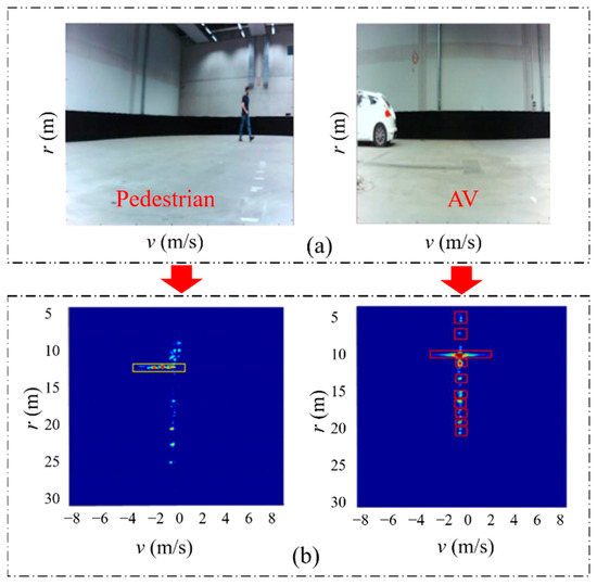
Figure 8.
Demonstration of a particular scenario of a pedestrian and a moving autonomous vehicle (AV). (a) Digital images; (b) RADAR information of the scene using support vector machine (SVM) and multi-objective optimization [84].
The RADAR sensor is used to measure information regarding the environment, and internal AV sensors measure acceleration, velocity, and position; the steering angle of autonomous vehicles and their speed are then evaluated on the basis of these parameters [85]. For example, a Mercedes-Benz S-Class vehicle equipped with almost six RADAR sensors was introduced in 2013, almost covering the complete 360° angular near and far range of the environment on each side of the vehicle. In normal traffic, the vehicle can cover almost 100 km, totally autonomously, from Mannheim to Pforzheim, Germany [86]. However, if sensors fail due to some fault, the autonomous vehicle cannot manage steering angle and speed adequately, resulting in catastrophic accidents. As a result, several studies on fault detection, isolation, and tolerance control have been carried out. The reliability of the RADAR system depends on the exploration of well-grounded approaches to detect faults, such as communication between vehicles, the geographical database of predefined roadside RADAR targets, the recognition of abrupt failures with the help of fuzzy logic and knowledge of the vehicle acceleration abilities, and the use of an unnecessary sensor that is fairly inexpensive but of poor quality. An experimental study showed an inexpensive redundant sensor coupled with a specifically designed nonlinear filter to be the most reliable solution for RADAR health monitoring [87]. Even when intervehicle communication is not available in a realistic highway environment, this approach would still work effectively. Figure 9 demonstrates the semiautonomous adaptive cruise controller (ACC), where both a RADAR sensor and an intervehicle communication system are present. Therefore, an intelligent system must be able to keep track of the health condition of both the intervehicle communication channel and the RADAR sensor [88].
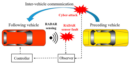
Figure 9.
Fault diagnostics for radio detection and ranging (RADAR) and intervehicle communication system.
To prevent collisions and assure safety on the road, the automotive RADAR must be fault proof, and its reliability and performance should be tested repeatedly, which requires proper diagnostic of well-functioning RADAR, so that the AV may participate in traffic. Calibration in relevant service stations is one way to test the performance of automotive RADAR. In contrast to offline calibration in service stations, the other way to diagnose the adequate functioning of automotive RADAR would be by means of monitoring the state, i.e., the health of the RADAR in real time [89]. If any changes occur in the performance of RADAR unit components, the fault prediction of the RADAR system is used to monitor those changes. As a result, it should dynamically monitor and control impacts on the performance of RADAR unit components, identify and manage the occurrence and progression of the fault, and provide sufficient time and decision-making basis for fault prevention and clearance. It should also be able to forecast the state of the RADAR in the future, determine the remaining life, plan maintenance, and ensure supply. Fault prediction based on reliability data, prediction parameter monitoring, cumulative damage model, and early warning circuit are some of the methods used to predict faults on the basis of the physical characteristics of RADAR [26]. Eventually, the objective of RADAR system PHM is to coordinate and rationally deploy maintenance support resources, as well as automatically develop and implement the maintenance strategy. Table 6 describes the research work that outlines the faults in RADAR and strategies utilized by various researchers to resolve them in the AV.
Table 6.
Demonstration of radio detection and ranging (RADAR) fault types and the fault detection mechanism.
3.4. Ultrasonic Sensors
An ultrasonic sensor (also called sonar) is a device that makes use of the echolocation phenomenon to determine if an object is in the domain of the sensor. Figure 10 depicts the typical ultrasonic echolocation of the sensor [27]. The ultrasonic sensor can also determine the target distance by tracing the time for a signal to return to the ultrasonic sensor after it has been emitted. On the other hand, ultrasonic sensors have interference due to noise and blind zones in close proximity, which can lead to inaccurate readings [27]. Materials with high sonic wave absorption coefficients and damping capabilities, such as acoustic foam, might also affect ultrasonic sensor readings [93].
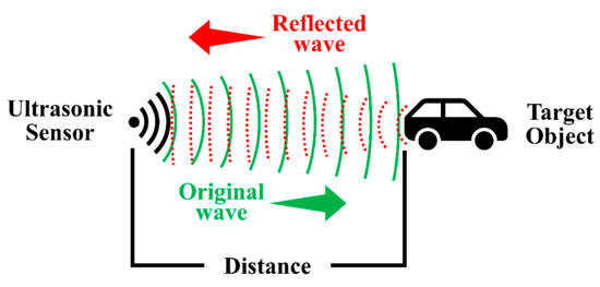
Figure 10.
Echolocation used by ultrasonic sensors.
Numerous AVs use ultrasonic sensors on the market to identify obstacles and aid in driving and parking. This section discusses the importance of ultrasonic sensors in giving comprehensive information about objects surrounding the vehicle. These sensors are mostly placed in vehicle bumpers, and operate at frequencies in the range 25–50 kHz [94]. They also provide additional useful information, such as the speed of the vehicle and the number of vehicles in a given distance [95]. However, they are highly sensitive to temperature and environment. Ultrasonic sensors are economical and have a straightforward installation method; they are extensively used in intelligent parking systems to locate available parking spaces [96,97,98]. Ultrasonic sensor-based autonomous vehicle detection and ZigBee-based communication between detection sensors were used to achieve the smart parking solution using a RabbitCore microcontroller by Idris et al. [99]. While entering and exiting the parking lot, they employed the shortest path algorithm to identify the closest parking place and exit position near the current car location. The Smart Parking System (SPS) needs specific directions to be followed by drivers in a certain way, and any deviation would lead toward failure. Another innovation is Park Assist, which utilizes an ultrasonic sensor to identify obstacles and find optimal steering angles for parking [100,101]. The information from the backup camera is combined with readings of the sensor to provide driver data about the parking. This distinct feature is only accessible when the vehicle is progressing at slow speed; despite this, there are typically secure mechanisms to prevent the wheel from overturning. Tesla has also merged such attributes in its vehicle, recognized as the Summon self-parking feature [102]. Similarly, the ultrasonic sensors were used by Kianpisheh et al. to locate vehicles in multilevel parking lots [95]. However, additional horizontal sensors installed on the walls of parking were used to spot inappropriate parking, and an alarm was triggered to report improper parking position to the driver. In this method, smart parking using three sensors was achieved; nevertheless, three sensors per parking place are not feasible, and more cost-effectiveness research studies should be carried out. Hence, to overcome the shortcomings of the existing method, Ma et al. proposed a multi-sensor-based parking space recognition method [103]. In this method, LiDAR is used to detect the edge points of parking spaces. A camera is also employed to extract the contours of parking spaces edges. In addition, it integrates the length of the library detected by the LiDAR with the contours of the parking space edges extracted from image, to decide whether the parking space matches the requirements. This technique can enhance parking space resources by identifying parking spots in more complex situations.
Although ultrasonic sensors have significantly contributed to the AV sector, fault detection and PHM of ultrasonic-based devices are very important to reduce severe roadside impacts. Lim et al. highlighted some of the undesirable situations of ultrasonic sensors [27]. The scenario involved blind-spot range, which is altered by the exposed exterior obstacle area; covering the ultrasonic transmitter and/or receiver can compromise the accuracy of detection. The specific target material may also cause inaccurate reading of the ultrasonic sensor, and sensor readings can be altered if any secondary sensor or sound wave device causes interference to the primary sensor output. Vehicle corner detection is another problem related to the ultrasonic sensor in AVs. To detect vehicle corners precisely, various designs are used. Two types of approaches are commonly employed to reduce the vehicle error of corner detection. In the first approach, the ultrasonic sensor’s transducer is modified to minimize the width of the beam [28]. In the second approach, multiple echo signal processing methods are applied to reduce vehicle corner error [16]. Table 7 presents some other faults associated with ultrasonic sensors, along with their consequences.
Table 7.
Demonstration of ultrasonic sensor fault types and their detection mechanism.
3.5. Positioning Sensors
Whether aerial, land, or sea-based, all kinds of autonomous vehicles require a positioning system to locate their position. The global navigation satellite system (GNSS) is the most widespread technology used for this purpose. The GNSS relies on satellites orbiting the Earth at approximately 20,000 km from the Earth’s surface. The GNSS system emits a signal, and a receiver decodes this signal to extract the information of the receiver’s position, time, and speed. The Global Positioning System (GPS) is the most common GNSS system freely available to be used in any part of the world [111]. In addition to GPS, other commonly available GNSSs are GLONASS, GALILEO, and BEIDOU. Each requires input signals from at least four of the 12 available GNSS satellites to provide an accurate 3D position (x, y, z) information, along with the time-of-flight between transmitter satellites and receiver [112,113]. Changle Li et al. classified GPS errors into three main categories: GPS satellites, signal propagation, and error at the receiver’s end [29]. These categories were further elaborated by Sara et al. to monitor the GPS accuracy for AVs. In addition to the aforementioned errors, the refraction of the GPS signal in the atmospheric layer was mentioned to be a cause of error in GPS signal [114]. Figure 11 illustrates this phenomenon [114,115]. The same phenomenon was used by Catherine et al. for motion planning of AVs [115].
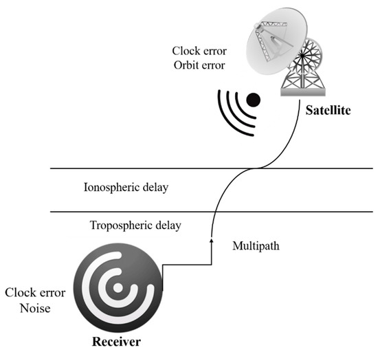
Figure 11.
Principal Global Positioning System (GPS) errors.
Due to the involved damage in testing the developed GPS algorithms, researchers prefer applying their proposed methodologies on prototypes; for example, Wan Rahiman et al. tested their proposed algorithm on a prototype vehicle that reaches its destination in three steps, using input from GPS [116]. The major drawback of GPS for AVs is degradation in its accuracy when there is no direct line of sight between satellite (transmitter) and vehicle (receiver), e.g., inside a tunnel or near tall buildings [116]. Hence, during the past few decades, many researchers have tried adding other positioning systems and GPS to improve the AV’s overall positioning accuracy. Kojima et al. used a laser system and GPS to track the positioning of a vehicle and determine its surrounding objects [117]. Elsewhere, Zein et al. applied a mechatronic system, which enabled the GPS tracking system to remember routes taken during supervised driving [118]. A positioning system developed by Quddus et al. relies on digital road map and machine vision to determine the surroundings to ensure vehicle safety [119].
Assessing the probability of GNSS satellite fault is a well-formulated framework in the context of autonomous applications. However, autonomous vehicles operate in unpredictable conditions, which leads to additional challenges [120]. Some of the major challenges described in [121] include static infrastructure, such as buildings and thick foliage, and dynamic obstacles, such as traffic and pedestrians. Various faults, such as satellite faults and received signal faults, have been identified for the GNSS system. Satellite faults [20] occur due to anomalies in different GNSS segments, i.e., receiver malfunction in the user segment, clock anomalies in the space segment, and satellite broadcast anomalies due to the control segment. Table 8 summarizes the different fault types and techniques of the GNSS.
Table 8.
Summary of global navigation satellite system (GNSS) system fault detection and isolation.
In addition to the error due to the signal disappearance of GPS satellites, there can be other kinds of errors in the positioning of AVs. During the testing of positioning systems, most researchers prefer indoor or controlled environments. Bader et al. proposed a fault-tolerant approach in multi-sensor data fusion, relying on the duplication–comparison method. The value of their method was explained using a case study using real data and fault injection implemented with Kalman filter for the positioning of a mobile robot. Figure 12 describes the basic working of the proposed architecture. Here, the results of both fusion blocks are compared with each other. The deviation between the compared results indicates the presence of error in the system. Using the remaining values from fusion and output of the sensor, it can be determined whether the source of error is software- or hardware-based. In a case study, an actual vehicle was localized using the data from the accelerometer, gyrometer, and odometer, feeding them to a Kalman filter and taking data from another odometer and GPS, before providing them to another Kalman filter. Lastly, the fault tolerance of the considered vehicles was evaluated using experimental data and fault injection, and the objective of their work was presented in terms of fault detection and system recovery [128].
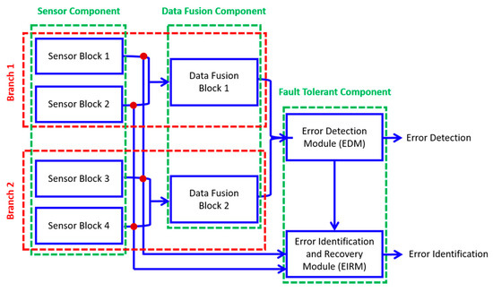
Figure 12.
Duplication–comparison architecture for fault tolerance in multisensory perception.
Bijjahalli et al. [129] presented a hierarchical approach at a component level along with hybrid Bayesian networks for the detection of a fault in GPS sensors, particularly multipath or antenna masking problems for GPS. The proposed method deals with GPS issues, such as multipath of signal, complete loss of signal, and antenna masking. The modern world requirement of real-time positions, particularly with high accuracy, led to the emergence of the real-time kinematic GPS (RTK GPS) strategy because of its easy implementation and productivity. RTK GPS, like all GPS techniques, is susceptible to multipath errors. Notwithstanding, RTK GPS, like all GPS techniques, has imperfections and inconsistencies. A multipath error appears if GPS signals are reflected from the ground or other objects together around the receiver, likely to result in a systematic error in the simulation of the range between both the satellite and the receiver. The GPS monitor shown in Figure 13 takes care of the sensor’s real-time kinematic (RTK) correction status, the number of active satellites, and the covariance of data provided by the sensor.
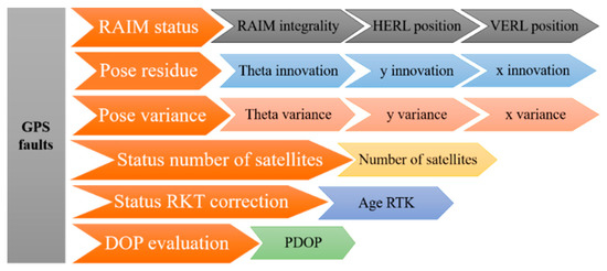
Figure 13.
Global positioning system (GPS) diagnostic hybrid Bayesian network.
3.6. Discussion
The PHM process can be affected by variations in the domain such as car type, onboard sensor configurations, and sensor algorithms. To elaborate, it is one of the key challenges to developing a globalized PHM model that would be capable of working under various kinds of conditions such as different types of cars. Moreover, the PHM technology has a discrepancy in adaptation from the lab scale to the real environmental conditions. In view of that, the outside environmental conditions such as external interference and noise can affect the sensor data, which ultimately affects the PHM process. The generalization capabilities can be affected when applying the developed model from one type of AV to another. In addition, for an effective PHM model, the onboard sensor suites are key for real-time PHM analysis. However, some physical obstacles restrict the onboard processing for the PHM process. Firstly, if the processing requires extensive computation and high speeds, this would consume substantially more energy. Secondly, the availability of memory constraints, such as running complex software necessitates a significant amount of memory. Because of these two constraints, embedding complex algorithms into onboard processing units is a complicated task. Other constraints include access to the most suitable sensing regions due to limited sensing environments or uninhabitable or toxic surroundings. To sum up, these are the important issues when developing a PHM strategy for AV technology [49].
4. Challenges and Future Perspectives AVs and Its PHM
The autonomous vehicle is an underdeveloped technology, and extensive research potential exists to develop the AVs. Hence, various researchers are testing AV technology for real-world implementation. However, multiple challenges have been identified during the testing phases of the AVs. Table 9 shows some of the crashes during the testing phase. In addition, various issues are involved in the development phases of the AVs, such as environmental and traffic safety aspects, legal aspects, and moral and ethical aspects [130]. Knowledge of the environment continues to be the most challenging obstacle to dependable, smooth, and safe driving [131]. Customer acceptance, social and economic impacts, telecommunication, ethical considerations, planning, guidelines, and policy are just a few of the research questions that must be addressed [132]. Software concerns, such as system security and reliability, have also emerged as significant issues that need to be acknowledged. There are a series of policy implications and difficulties that policymakers have in optimizing and governing a diverse range of vehicles with varying operational limitations. Policymakers must also ensure that drivers are aware of the capabilities of these vehicles and can operate them safely. One of the challenges is connecting several smart cars to the facilities that require big data. This term refers to the processing and analysis of large datasets [133].
Table 9.
Various accidents during the development of autonomous vehicle (AV) technology.
As mentioned above, the PHM for AV technology is still progressing, with a wide range of research objectives. However, understanding the overall shape of technology and its trajectory is incredibly challenging. The majority of the work defines problems within a very narrow range, with numerous constraints. Most of the available literature could not cover the overall sensor assessment of the AVs, which is a complicated task in terms of data handling. Real-time PHM is needed for the AV technology under real environmental scenarios. Furthermore, it is a quite challenging task to develop a PHM system for the AV that works under different operating conditions. It is a complicated process to compensate for the lab-scale model in real environmental conditions because of the complex working conditions in real-time applications. The data collection system makes the working environment bulkier in actual scenarios. These are key issues to be addressed in a real-time PHM of AVs. AVs are composed of different kinds of sensors. Complementary data from various sensors can be used to compensate for individual sensor inaccuracies and operating ranges. As a result, the overall information is accurate over an extensive range. However, it is challenging to propose an FDI algorithm that simultaneously diagnoses the fault in individual sensors. Similarly, it is complicated to deal with overall “big data” for all sensors collectively. In addition, it is a comparatively easy task to detect and eliminate hard faults. However, soft faults are more difficult to detect and eliminate because sensor data take time to leave a confidence limit [58]. While Google, GM, BMW, and Tesla will each experiment and test various AVs, traditional software bugs are more difficult to fix than DNN-based software bugs [56]. The Kalman filter variants have widespread application among existing quantitative model-based methods due to their simplicity and ability to handle reasonable uncertainties and nonlinearities. However, the presence of Gaussian noise complicates fault diagnosis [21]. In addition, controlling external light, which acts as noise during image processing, is one of the key issues for AVs [59].
AV safety is one of the most crucial features that require special attention at all stages of the vehicle’s lifetime. Software failures can be costly in terms of recalls, and they can even be fatal. The failure or malfunction of an automotive system can cause serious injuries or death. Hence, the overall safety of AVs can be improved in various aspects such as passive, active, or functional safety. Safety-related intervehicle communication (IVC) is one of the crucial hazards in AV technology. However, the reliability of dedicated short-range communication (DSRC) performance is inadequate to guarantee vehicle stability execution in such circumstances. Over the years, various approaches have been proposed to resolve IVC-based safety. For instance, Yu and Biswas [5] proposed a unique DSRC-based medium access control (MAC) framework for IVC that comprised a self-configuring time division of numerous guidelines with short and deterministic time lag-linked capabilities. Furthermore, the distributed power control method was suggested to control a load of periodic messages on the channel [6]. Bi et al. [7] introduced a cross-layer broadcast protocol for efficient and dependable message delivery in IVC systems. Palazzi et al. [8] proposed an innovative IVC framework that adjusts its features and functionality to deliver implementations efficiently by rapidly perpetuating their communications across a vehicular network. Tabatabaei et al. [9] improved simpler network topologies for simulation models by enhancing ray-tracing-derived wireless propagation models.
Various issues are concerns to adopt the AV technology on a large scale such as legal obligations, ethical implications, confidentiality issues, data protection and hacking, and the massive cost of vehicles and related technologies. On the other hand, the future of AV technology is brighter because of its peculiar features such as the pervasive utilization of AVs on highways resulting in fewer traffic accidents, efficiency in terms of fuel usage, and increased productivity. Hence, it appears that the gradual substitution of conventional vehicles with AVs will take place, with the main factor being society’s adjustment to this type of innovation and corresponding features. Researchers and specialists anticipate that AVs will be widely adopted in the coming 20 to 25 years. According to the surveys, depending on the level of advancement, the AV technology can be adopted until 2030–2040 in well-developed nations with decent infrastructure [137].
5. Conclusions
Recent years have seen a rise in self-driving autonomous vehicles (AVs), where the advanced driver assistance system (ADAS) plays a critical role. It is imperative for traffic safety and higher driving efficiency to carry out timely diagnosis (detection, quantification, and isolation of faults) and prognosis (future evaluation of defects) of the main components of ADAS in the framework of prognostic health management (PHM). This article provided an extensive review of the main features of ADAS, the types of faults in each different sensor, and the research efforts related to PHM from the published literature.
The detailed discussion of the possible shortcomings and commonly occurring defects, as well as the PHM efforts, are summarized for different ADAS components below.
- For the LiDAR system, the sensor-based faults are malfunction of mirror motor, damage to optical filter, misalignment of the optical receiver, security breach, adverse climatic circumstances, intermodulation distortion, and short-circuit and overvoltage of electrical components. Some representative PHM efforts for LiDAR are correlation with sensor framework, output of the monitoring sensor, correlation to passive ground truth, correlation to active ground truth, correlation to another similar sensor, and correlation to a different sensor.
- RADAR is more economical than LiDAR and cameras, and it works on the principle of the Doppler effect. The primary failure modes of RADAR are fault in the range rate signal and sensor fault. Some preventive and corrective measures for RADAR are calibration in relevant service stations, sliding mode observer, sensor fault detection, cyberattack detection observer, and the LSTM-based deep learning approach.
- The ultrasonic sensors used to determine an object in the domain of the sensors are susceptible to acoustic/electronic noise, performance degradation under bright ambient light, vehicle corner error, and cross echoes, among others. Common approaches for detecting faults and corrective measures in ultrasonic sensors are artificial neural networks, parallel parking assist systems, combined ultrasonic sensors and three-dimensional vision sensors, and grid maps.
- The positioning sensors and systems employed to locate the position of AVs are prone to jumps in GPS observation, satellite and received signal faults, and sensor data with/without curbs on the roadsides. The techniques employed for the fault detection and isolation of positioning sensors and systems are the Kalman filter, Markov blanket (MB) algorithm, and sensor redundancy fault detection model.
The AVs and the PHM of its main components are not yet fully developed, and a great deal of research is needed to fully develop reliable autonomous driving. This article discussed the existing research efforts to highlight the current techniques, as well as identified potential research gaps. To sum up, the current review paper is a first attempt at highlighting the fault detection for the overall sensors of the ADAS for AVs, which provides insight to readers on the current progress and potential research gaps in this field. The current study identified different faults in various sensors using fault diagnosis techniques, which can motivate readers toward further research to overcome the existing challenges in this field.
Author Contributions
Conceptualization, H.S.K. and I.R.; methodology, I.R.; formal analysis, I.R.; investigation, I.R., A.K. and S.K.; resources, H.S.K.; writing—original draft preparation, I.R., A.K., S.K., M.S. and M.M.A.; writing—review and editing, H.S.K., A.K. and S.K.; visualization, I.R. and H.S.K.; supervision, H.S.K.; project administration, H.S.K.; funding acquisition, H.S.K. All authors have read and agreed to the published version of the manuscript.
Funding
This work was supported by the Ministry of Trade, Industry, and Energy (MOTIE) and the Korea Institute for Advancement of Technology (KIAT) through the International Cooperative R&D program (Project No. P0011923), as well as by a National Research Foundation of Korea (NRF) grant, funded by the Korea government (MSIT) (No. 2020R1A2C1006613).
Conflicts of Interest
The authors declare no conflict of interest.
References
- Meyer-Waarden, L.; Cloarec, J. “Baby, You Can Drive My Car”: Psychological Antecedents That Drive Consumers’ Adoption of AI-Powered Autonomous Vehicles. Technovation 2022, 109, 102348. [Google Scholar] [CrossRef]
- Nowicki, M.R. A Data-Driven and Application-Aware Approach to Sensory System Calibration in an Autonomous Vehicle. Measurement 2022, 194, 111002. [Google Scholar] [CrossRef]
- Jain, S.; Ahuja, N.J.; Srikanth, P.; Bhadane, K.V.; Nagaiah, B.; Kumar, A.; Konstantinou, C. Blockchain and Autonomous Vehicles: Recent Advances and Future Directions. IEEE Access 2021, 9, 130264–130328. [Google Scholar] [CrossRef]
- Reid, T.G.; Houts, S.E.; Cammarata, R.; Mills, G.; Agarwal, S.; Vora, A.; Pandey, G. Localization Requirements for Autonomous Vehicles. arXiv 2019, arXiv:1906.01061. [Google Scholar] [CrossRef]
- Yu, F.; Biswas, S. Self-Configuring TDMA Protocols for Enhancing Vehicle Safety with DSRC Based Vehicle-to-Vehicle Communications. IEEE J. Sel. Areas Commun. 2007, 25, 1526–1537. [Google Scholar] [CrossRef]
- Torrent-Moreno, M.; Mittag, J.; Santi, P.; Hartenstein, H. Vehicle-to-Vehicle Communication: Fair Transmit Power Control for Safety-Critical Information. IEEE Trans. Veh. Technol. 2009, 58, 3684–3703. [Google Scholar] [CrossRef]
- Bi, Y.; Cai, L.X.; Shen, X.; Zhao, H. Efficient and Reliable Broadcast in Intervehicle Communication Networks: A Cross-Layer Approach. IEEE Trans. Veh. Technol. 2010, 59, 2404–2417. [Google Scholar] [CrossRef]
- Palazzi, C.E.; Roccetti, M.; Ferretti, S. An Intervehicular Communication Architecture for Safety and Entertainment. IEEE Trans. Intell. Transp. Syst. 2009, 11, 90–99. [Google Scholar] [CrossRef]
- Tabatabaei, S.A.H.; Fleury, M.; Qadri, N.N.; Ghanbari, M. Improving Propagation Modeling in Urban Environments for Vehicular Ad Hoc Networks. IEEE Trans. Intell. Transp. Syst. 2011, 12, 705–716. [Google Scholar] [CrossRef]
- You, J.-H.; Oh, S.; Park, J.-E.; Song, H.; Kim, Y.-K. A Novel LiDAR Sensor Alignment Inspection System for Automobile Productions Using 1-D Photodetector Arrays. Measurement 2021, 183, 109817. [Google Scholar] [CrossRef]
- Kala, R.; Warwick, K. Motion Planning of Autonomous Vehicles in a Non-Autonomous Vehicle Environment without Speed Lanes. Eng. Appl. Artif. Intell. 2013, 26, 1588–1601. [Google Scholar] [CrossRef]
- Correa-Caicedo, P.J.; Barranco-Gutiérrez, A.I.; Guerra-Hernandez, E.I.; Batres-Mendoza, P.; Padilla-Medina, J.A.; Rostro-González, H. An FPGA-Based Architecture for a Latitude and Longitude Correction in Autonomous Navigation Tasks. Measurement 2021, 182, 109757. [Google Scholar]
- Duran, O.; Turan, B. Vehicle-to-Vehicle Distance Estimation Using Artificial Neural Network and a Toe-in-Style Stereo Camera. Measurement 2022, 190, 110732. [Google Scholar] [CrossRef]
- Duran, D.R.; Robinson, E.; Kornecki, A.J.; Zalewski, J. Safety Analysis of Autonomous Ground Vehicle Optical Systems: Bayesian Belief Networks Approach. In Proceedings of the 2013 Federated Conference on Computer Science and Information Systems, Kraków, Poland, 8–11 September 2013; pp. 1419–1425. [Google Scholar]
- Woongsun, J.; Ali, Z.; Rajesh, R. Resilient Control Under Cyber-Attacks in Connected ACC Vehicles. In Proceedings of the ASME 2019 Dynamic Systems and Control Conference, Park City, UT, USA, 8–11 October 2019. [Google Scholar]
- Park, W.J.; Kim, B.S.; Seo, D.E.; Kim, D.S.; Lee, K.H. Parking Space Detection Using Ultrasonic Sensor in Parking Assistance System. In Proceedings of the 2008 IEEE Intelligent Vehicles Symposium, Eindhoven, The Netherlands, 4–6 June 2008; pp. 1039–1044. [Google Scholar] [CrossRef]
- van Schaik, W.; Grooten, M.; Wernaart, T.; van der Geld, C. High Accuracy Acoustic Relative Humidity Measurement in Duct Flow with Air. Sensors 2010, 10, 7421–7433. [Google Scholar] [CrossRef]
- Alonso, L.; Milanés, V.; Torre-Ferrero, C.; Godoy, J.; Oria, J.P.; de Pedro, T. Ultrasonic Sensors in Urban Traffic Driving-Aid Systems. Sensors 2011, 11, 661–673. [Google Scholar] [CrossRef]
- Sahoo, A.K.; Udgata, S.K. A Novel ANN-Based Adaptive Ultrasonic Measurement System for Accurate Water Level Monitoring. IEEE Trans. Instrum. Meas. 2020, 69, 3359–3369. [Google Scholar] [CrossRef]
- Blanch, J.; Walter, T.; Enge, P. A Simple Satellite Exclusion Algorithm for Advanced RAIM. In Proceedings of the 2016 International Technical Meeting of The Institute of Navigation, Monterey, CA, USA, 25–28 January 2016; pp. 239–244. [Google Scholar]
- Mori, D.; Sugiura, H.; Hattori, Y. Adaptive Sensor Fault Detection and Isolation Using Unscented Kalman Filter for Vehicle Positioning. In Proceedings of the 2019 IEEE Intelligent Transportation Systems Conference (ITSC), Auckland, New Zealand, 27–30 October 2019; IEEE: Piscataway, NJ, USA, 2019; pp. 1298–1304. [Google Scholar]
- Tadjine, H.; Anoushirvan, D.; Eugen, D.; Schulze, K. Optical Self Diagnostics for Camera Based Driver Assistance. In Proceedings of the FISITA 2012 World Automotive Congress; SAE-China, FISITA, Eds.; Lecture Notes in Electrical Engineering; Springer: Berlin/Heidelberg, Germany, 2013; Volume 197, pp. 507–518. ISBN 978-3-642-33804-5. [Google Scholar]
- Saponara, S.; Greco, M.S.; Gini, F. Radar-on-Chip/in-Package in Autonomous Driving Vehicles and Intelligent Transport Systems: Opportunities and Challenges. IEEE Signal Processing Mag. 2019, 36, 71–84. [Google Scholar] [CrossRef]
- Park, S.; Oh, K.; Jeong, Y.; Yi, K. Model Predictive Control-Based Fault Detection and Reconstruction Algorithm for Longitudinal Control of Autonomous Driving Vehicle Using Multi-Sliding Mode Observer. Microsyst. Technol. 2020, 26, 239–264. [Google Scholar] [CrossRef]
- Oh, K.; Yi, K. A Longitudinal Model Based Probabilistic Fault Diagnosis Algorithm of Autonomous Vehicles Using Sliding Mode Observer. In Proceedings of the ASME 2017 Conference on Information Storage and Processing Systems, San Francisco, CA, USA, 29–30 August 2017; American Society of Mechanical Engineers: New York, NY, USA, 2017; pp. 1–3. [Google Scholar]
- Lyu, Y.; Pang, Z.; Zhou, C.; Zhao, P. Prognostics and Health Management Technology for Radar System. MATEC Web Conf. 2020, 309, 04009. [Google Scholar] [CrossRef][Green Version]
- Lim, B.S.; Keoh, S.L.; Thing, V.L.L. Autonomous Vehicle Ultrasonic Sensor Vulnerability and Impact Assessment. In Proceedings of the IEEE World Forum on Internet of Things (WF-IoT), Singapore, 5–8 February 2018; pp. 231–236. [Google Scholar] [CrossRef]
- Bank, D. A Novel Ultrasonic Sensing System for Autonomous Mobile Systems. Proc. IEEE Sens. 2002, 1, 1671–1676. [Google Scholar] [CrossRef]
- Li, C.; Fu, Y.; Yu, F.R.; Luan, T.H.; Zhang, Y. Vehicle Position Correction: A Vehicular Blockchain Networks-Based GPS Error Sharing Framework. IEEE Trans. Intell. Transp. Syst. 2021, 22, 898–912. [Google Scholar] [CrossRef]
- Hu, J.; Sun, Q.; Ye, Z.-S.; Zhou, Q. Joint Modeling of Degradation and Lifetime Data for RUL Prediction of Deteriorating Products. IEEE Trans. Ind. Inf. 2021, 17, 4521–4531. [Google Scholar] [CrossRef]
- Ye, Z.-S.; Xie, M. Stochastic Modelling and Analysis of Degradation for Highly Reliable Products: Z.-S. YE AND M. XIE. Appl. Stochastic Models Bus. Ind. 2015, 31, 16–32. [Google Scholar] [CrossRef]
- Ng, T.S. ADAS in Autonomous Driving. In Robotic Vehicles: Systems and Technology; Springer: Berlin/Heidelberg, Germany, 2021; pp. 87–93. [Google Scholar]
- Li, X.; Lin, K.-Y.; Meng, M.; Li, X.; Li, L.; Hong, Y. Composition and Application of Current Advanced Driving Assistance System: A Review. arXiv 2021, arXiv:2105.12348. [Google Scholar]
- Choi, J.D.; Kim, M.Y. A Sensor Fusion System with Thermal Infrared Camera and LiDAR for Autonomous Vehicles and Deep Learning Based Object Detection. ICT Express, 2022, in press. [CrossRef]
- Wang, H.; Wang, B.; Liu, B.; Meng, X.; Yang, G. Pedestrian Recognition and Tracking Using 3D LiDAR for Autonomous Vehicle. Robot. Auton. Syst. 2017, 88, 71–78. [Google Scholar] [CrossRef]
- Khan, A.; Khalid, S.; Raouf, I.; Sohn, J.-W.; Kim, H.-S. Autonomous Assessment of Delamination Using Scarce Raw Structural Vibration and Transfer Learning. Sensors 2021, 21, 6239. [Google Scholar] [CrossRef]
- Raouf, I.; Lee, H.; Kim, H.S. Mechanical Fault Detection Based on Machine Learning for Robotic RV Reducer Using Electrical Current Signature Analysis: A Data-Driven Approach. J. Comput. Des. Eng. 2022, 9, 417–433. [Google Scholar] [CrossRef]
- Habibi, H.; Howard, I.; Simani, S.; Fekih, A. Decoupling Adaptive Sliding Mode Observer Design for Wind Turbines Subject to Simultaneous Faults in Sensors and Actuators. IEEE/CAA J. Autom. Sin. 2021, 8, 837–847. [Google Scholar] [CrossRef]
- Saeed, U.; Jan, S.U.; Lee, Y.-D.; Koo, I. Fault Diagnosis Based on Extremely Randomized Trees in Wireless Sensor Networks. Reliab. Eng. Syst. Saf. 2021, 205, 107284. [Google Scholar] [CrossRef]
- Bellanco, I.; Fuentes, E.; Vallès, M.; Salom, J. A Review of the Fault Behavior of Heat Pumps and Measurements, Detection and Diagnosis Methods Including Virtual Sensors. J. Build. Eng. 2021, 39, 102254. [Google Scholar] [CrossRef]
- Rajpoot, S.C.; Pandey, C.; Rajpoot, P.S.; Singhai, S.K.; Sethy, P.K. A Dynamic-SUGPDS Model for Faults Detection and Isolation of Underground Power Cable Based on Detection and Isolation Algorithm and Smart Sensors. J. Electr. Eng. Technol. 2021, 16, 1799–1819. [Google Scholar] [CrossRef]
- Bhushan, B.; Sahoo, G. Recent Advances in Attacks, Technical Challenges, Vulnerabilities and Their Countermeasures in Wireless Sensor Networks. Wirel. Pers. Commun. 2018, 98, 2037–2077. [Google Scholar] [CrossRef]
- Goelles, T.; Schlager, B.; Muckenhuber, S. Fault Detection, Isolation, Identification and Recovery (FDIIR) Methods for Automotive Perception Sensors Including a Detailed Literature Survey for Lidar. Sensors 2020, 20, 3662. [Google Scholar] [CrossRef] [PubMed]
- Van Brummelen, J.; O’Brien, M.; Gruyer, D.; Najjaran, H. Autonomous Vehicle Perception: The Technology of Today and Tomorrow. Transp. Res. Part C Emerg. Technol. 2018, 89, 384–406. [Google Scholar]
- Biddle, L.; Fallah, S. A Novel Fault Detection, Identification and Prediction Approach for Autonomous Vehicle Controllers Using SVM. Automot. Innov. 2021, 4, 301–314. [Google Scholar] [CrossRef]
- Sun, Q.; Ye, Z.-S.; Zhu, X. Managing Component Degradation in Series Systems for Balancing Degradation through Reallocation and Maintenance. IISE Trans. 2020, 52, 797–810. [Google Scholar]
- Gu, J.; Barker, D.; Pecht, M.G. Uncertainty Assessment of Prognostics of Electronics Subject to Random Vibration. In Proceedings of the AAAI Fall Symposium: Artificial Intelligence for Prognostics, Arlington, VA, USA, 9–11 November 2007; pp. 50–57. [Google Scholar]
- Ibargüengoytia, P.H.; Vadera, S.; Sucar, L.E. A Probabilistic Model for Information and Sensor Validation. Comput. J. 2006, 49, 113–126. [Google Scholar] [CrossRef]
- Cheng, S.; Azarian, M.H.; Pecht, M.G. Sensor Systems for Prognostics and Health Management. Sensors 2010, 10, 5774–5797. [Google Scholar] [CrossRef]
- Gong, Z.; Lin, H.; Zhang, D.; Luo, Z.; Zelek, J.; Chen, Y.; Nurunnabi, A.; Wang, C.; Li, J. A Frustum-Based Probabilistic Framework for 3D Object Detection by Fusion of LiDAR and Camera Data. ISPRS J. Photogramm. Remote Sens. 2020, 159, 90–100. [Google Scholar] [CrossRef]
- SAE-China; FISITA (Eds.) Proceedings of the FISITA 2012 World Automotive Congress; Springer: Berlin/Heidelberg, Germany, 2013; ISBN 3-642-33840-2. [Google Scholar]
- Kobayashi, T.; Simon, D.L. Application of a Bank of Kalman Filters for Aircraft Engine Fault Diagnostics. In Proceedings of the ASME Turbo Expo 2003, Atlanta, GA, USA, 16–19 June 2003; Volume 1, pp. 461–470. [Google Scholar]
- Salahshoor, K.; Mosallaei, M.; Bayat, M. Centralized and Decentralized Process and Sensor Fault Monitoring Using Data Fusion Based on Adaptive Extended Kalman Filter Algorithm. Measurement 2008, 41, 1059–1076. [Google Scholar] [CrossRef]
- Köylüoglu, T.; Hennicks, L. Evaluating Rain Removal Image Processing Solutions for Fast and Accurate Object Detection. Master’s Thesis, KTH Royal Institute of Technology, Stockholm, Sweden, 2019. [Google Scholar]
- Realpe, M. Multi-Sensor Fusion Module in a Fault Tolerant Perception System for Autonomous Vehicles. J. Autom. Control. Eng. 2016, 4, 460–466. [Google Scholar] [CrossRef]
- Sculley, D.; Holt, G.; Golovin, D.; Davydov, E.; Phillips, T.; Ebner, D.; Chaudhary, V.; Young, M. Machine Learning: The High Interest Credit Card of Technical Debt. 2014. Available online: https://blog.acolyer.org/2016/02/29/machine-learning-the-high-interest-credit-card-of-technical-debt/ (accessed on 10 August 2022).
- Spinneker, R.; Koch, C.; Park, S.-B.; Yoon, J.J. Fast Fog Detection for Camera Based Advanced Driver Assistance Systems. In Proceedings of the 17th International IEEE Conference on Intelligent Transportation Systems (ITSC), Qingdao, China, 8–11 October 2014; IEEE: Piscataway, NJ, USA, 2014; pp. 1369–1374. [Google Scholar]
- Tian, Y.; Pei, K.; Jana, S.; Ray, B. Deeptest: Automated Testing of Deep-Neural-Network-Driven Autonomous Cars. In Proceedings of the 40th International Conference on Software Engineering, Gothenburg, Sweden, 27 May–3 June 2018; pp. 303–314. [Google Scholar]
- Hata, A.; Wolf, D. Road Marking Detection Using LIDAR Reflective Intensity Data and Its Application to Vehicle Localization. In Proceedings of the 17th International IEEE Conference on Intelligent Transportation Systems (ITSC), Qingdao, China, 8–11 October 2014; IEEE: Piscataway, NJ, USA, 2014; pp. 584–589. [Google Scholar]
- Poczter, S.L.; Jankovic, L.M. The Google Car: Driving Toward A Better Future? JBCS 2013, 10, 7. [Google Scholar] [CrossRef]
- Yoo, H.W.; Druml, N.; Brunner, D.; Schwarzl, C.; Thurner, T.; Hennecke, M.; Schitter, G. MEMS-Based Lidar for Autonomous Driving. Elektrotech. Inftech. 2018, 135, 408–415. [Google Scholar] [CrossRef]
- Asvadi, A.; Premebida, C.; Peixoto, P.; Nunes, U. 3D Lidar-Based Static and Moving Obstacle Detection in Driving Environments: An Approach Based on Voxels and Multi-Region Ground Planes. Robot. Auton. Syst. 2016, 83, 299–311. [Google Scholar] [CrossRef]
- Segata, M.; Cigno, R.L.; Bhadani, R.K.; Bunting, M.; Sprinkle, J. A Lidar Error Model for Cooperative Driving Simulations. In Proceedings of the 2018 IEEE Vehicular Networking Conference (VNC), Taipei, Taiwan, 5–7 December 2018; IEEE: Piscataway, NJ, USA, 2018; pp. 1–8. [Google Scholar]
- Sun, X. Method and Apparatus for Detection and Ranging Fault Detection and Recovery. U.S. Patent 10,203,408, 12 February 2019. [Google Scholar]
- Rivero, J.R.V.; Tahiraj, I.; Schubert, O.; Glassl, C.; Buschardt, B.; Berk, M.; Chen, J. Characterization and Simulation of the Effect of Road Dirt on the Performance of a Laser Scanner. In Proceedings of the 2017 IEEE 20th International Conference on Intelligent Transportation Systems (ITSC), Yokohama, Japan, 16–19 October 2017; IEEE: Piscataway, NJ, USA, 2017; pp. 1–6. [Google Scholar]
- Trierweiler, M.; Caldelas, P.; Gröninger, G.; Peterseim, T.; Neumann, C. Influence of Sensor Blockage on Automotive LiDAR Systems. In Proceedings of the 2019 IEEE SENSORS, Montreal, QC, Canada, 27–30 October 2019; IEEE: Piscataway, NJ, USA, 2019; pp. 1–4. [Google Scholar]
- Periu, C.F.; Mohsenimanesh, A.; Laguë, C.; McLaughlin, N.B. Isolation of Vibrations Transmitted to a LIDAR Sensor Mounted on an Agricultural Vehicle to Improve Obstacle Detection. Can. Biosyst. Eng. 2013, 55, 233–242. [Google Scholar] [CrossRef]
- Hama, S.; Toda, H. Basic Experiment of LIDAR Sensor Measurement Directional Instability for Moving and Vibrating Object. In Proceedings of the IOP Conference Series: Materials Science and Engineering, Chongqing, China, 23–25 November 2018; IOP Publishing: Bristol, UK, 2019; Volume 472, p. 012017. [Google Scholar]
- Choi, H.; Lee, W.-C.; Aafer, Y.; Fei, F.; Tu, Z.; Zhang, X.; Xu, D.; Deng, X. Detecting Attacks against Robotic Vehicles: A Control Invariant Approach. In Proceedings of the 2018 ACM SIGSAC Conference on Computer and Communications Security, Toronto, ON, Canada, 15–19 October 2018; pp. 801–816. [Google Scholar]
- Petit, J.; Shladover, S.E. Potential Cyberattacks on Automated Vehicles. IEEE Trans. Intell. Transp. Syst. 2014, 16, 546–556. [Google Scholar] [CrossRef]
- Shin, H.; Kim, D.; Kwon, Y.; Kim, Y. Illusion and Dazzle: Adversarial Optical Channel Exploits against Lidars for Automotive Applications. In Proceedings of the International Conference on Cryptographic Hardware and Embedded Systems, Santa Barbara, CA, USA, 17–19 August 2016; Springer: Berlin/Heidelberg, Germany, 2017; pp. 445–467. [Google Scholar]
- Kim, G.; Eom, J.; Park, Y. An Experiment of Mutual Interference between Automotive LIDAR Scanners. In Proceedings of the 2015 12th International Conference on Information Technology-New Generations, Las Vegas, NV, USA, 13–15 April 2015; IEEE: Piscataway, NJ, USA, 2015; pp. 680–685. [Google Scholar]
- Zhang, F.; Liu, Q.; Gong, M.; Fu, X. Anti-Dynamic-Crosstalk Method for Single Photon LIDAR Detection. In LIDAR Imaging Detection and Target Recognition 2017; International Society for Optics and Photonics: Washington, DC, USA, 2017; Volume 10605, p. 1060503. [Google Scholar]
- Ning, X.; Li, F.; Tian, G.; Wang, Y. An Efficient Outlier Removal Method for Scattered Point Cloud Data. PLoS ONE 2018, 13, e0201280. [Google Scholar] [CrossRef]
- McMichael, R.; Schabb, D.E.; Thakur, A.; Francisco, S.; Kentley-Klay, D.; Torrey, J.R. Sensor Obstruction Detection and Mitigation Using Vibration and/or Heat. U.S. Patent 11,176,426, 16 November 2021. [Google Scholar]
- Bohren, J.; Foote, T.; Keller, J.; Kushleyev, A.; Lee, D.; Stewart, A.; Vernaza, P.; Derenick, J.; Spletzer, J.; Satterfield, B. Little Ben: The Ben Franklin Racing Team’s Entry in the 2007 DARPA Urban Challenge. J. Field Robot. 2008, 25, 598–614. [Google Scholar] [CrossRef]
- Fallis, A.G. Autonomous Ground Vehicle. J. Chem. Inf. Modeling 2013, 53, 1689–1699. [Google Scholar]
- Kesting, A.; Treiber, M.; Schönhof, M.; Helbing, D. Adaptive Cruise Control Design for Active Congestion Avoidance. Transp. Res. Part C Emerg. Technol. 2008, 16, 668–683. [Google Scholar] [CrossRef]
- Werneke, J.; Kleen, A.; Vollrath, M. Perfect Timing: Urgency, Not Driving Situations, Influence the Best Timing to Activate Warnings. Hum. Factors 2014, 56, 249–259. [Google Scholar] [CrossRef]
- Li, H.-J.; Kiang, Y.-W. Radar and Inverse Scattering. In The Electrical Engineering Handbook; Elsevier: Amsterdam, The Netherlands, 2005; pp. 671–690. [Google Scholar]
- Rohling, H.; Möller, C. Radar Waveform for Automotive Radar Systems and Applications. In Proceedings of the 2008 IEEE Radar Conference, RADAR, Rome, Italy, 26–30 May 2008; Volume 1. [Google Scholar] [CrossRef]
- Bilik, I.; Longman, O.; Villeval, S.; Tabrikian, J. The Rise of Radar for Autonomous Vehicles. IEEE Signal Process. Mag. 2019, 36, 20–31. [Google Scholar] [CrossRef]
- Campbell, S.; O’Mahony, N.; Krpalcova, L.; Riordan, D.; Walsh, J.; Murphy, A.; Ryan, C. Sensor Technology in Autonomous Vehicles: A Review. In Proceedings of the 29th Irish Signals and Systems Conference, ISSC, Belfast, UK, 21–22 June 2018; pp. 1–4. [Google Scholar] [CrossRef]
- Severino, J.V.B.; Zimmer, A.; Brandmeier, T.; Freire, R.Z. Pedestrian Recognition Using Micro Doppler Effects of Radar Signals Based on Machine Learning and Multi-Objective Optimization. Expert Syst. Appl. 2019, 136, 304–315. [Google Scholar] [CrossRef]
- Loureiro, R.; Benmoussa, S.; Touati, Y.; Merzouki, R.; Ould Bouamama, B. Integration of Fault Diagnosis and Fault-Tolerant Control for Health Monitoring of a Class of MIMO Intelligent Autonomous Vehicles. IEEE Trans. Veh. Technol. 2014, 63, 30–39. [Google Scholar] [CrossRef]
- Dickmann, J.; Appenrodt, N.; Bloecher, H.L.; Brenk, C.; Hackbarth, T.; Hahn, M.; Klappstein, J.; Muntzinger, M.; Sailer, A. Radar Contribution to Highly Automated Driving. In Proceedings of the 2014 44th European Microwave Conference, Rome, Italy, 6–9 October 2014; pp. 412–415. [Google Scholar] [CrossRef]
- Rajamani, R.; Shrivastava, A.; Zhu, C.; Alexander, L. Fault Diagnostics for Intelligent Vehicle Applications; Minnesota Department of Transportation: Saint Paul, MN, USA, 2001. [Google Scholar]
- Jeon, W.; Xie, Z.; Zemouche, A.; Rajamani, R. Simultaneous Cyber-Attack Detection and Radar Sensor Health Monitoring in Connected ACC Vehicles. IEEE Sens. J. 2021, 21, 15741–15752. [Google Scholar] [CrossRef]
- Yigit, E. Automotive Radar Self-Diagnostic Using Calibration Targets That Are Embedded in Road Infrastructure; Delft University of Technology: Delft, The Netherlands, 2021. [Google Scholar]
- Oh, K.; Park, S.; Lee, J.; Yi, K. Functional Perspective-Based Probabilistic Fault Detection and Diagnostic Algorithm for Autonomous Vehicle Using Longitudinal Kinematic Model. Microsyst. Technol. 2018, 24, 4527–4537. [Google Scholar] [CrossRef]
- Oh, K.; Park, S.; Yi, K. A Predictive Approach to the Fault Detection in Fail-Safe System of Autonomous Vehicle Based on the Multi-Sliding Mode Observer. In Proceedings of the ASME-JSME 2018 Joint International Conference on Information Storage and Processing Systems and Micromechatronics for Information and Precision Equipment, ISPS-MIPE, San Francisco, CA, USA, 29–30 August 2018; pp. 2018–2020. [Google Scholar] [CrossRef]
- Song, T.; Lee, J.; Oh, K.; Yi, K. Dual-Sliding Mode Approach for Separated Fault Detection and Tolerant Control for Functional Safety of Longitudinal Autonomous Driving. Proc. Inst. Mech. Eng. Part D J. Automob. Eng. 2021, 235, 1446–1460. [Google Scholar] [CrossRef]
- Cheek, E.; Khuttan, D.; Changalvala, R.; Malik, H. Physical Fingerprinting of Ultrasonic Sensors and Applications to Sensor Security. In Proceedings of the 2020 IEEE 6th International Conference on Dependability in Sensor, Cloud and Big Data Systems and Application, DependSys, Nadi, Fiji, 14–16 December 2020; pp. 65–72. [Google Scholar] [CrossRef]
- Al-Turjman, F.; Malekloo, A. Smart Parking in IoT-Enabled Cities: A Survey. Sustain. Cities Soc. 2019, 49, 101608. [Google Scholar] [CrossRef]
- Kianpisheh, A.; Mustaffa, N.; Limtrairut, P.; Keikhosrokiani, P. Smart Parking System (SPS) Architecture Using Ultrasonic Detector. Int. J. Softw. Eng. Its Appl. 2012, 6, 51–58. [Google Scholar]
- Kotb, A.O.; Shen, Y.C.; Huang, Y. Smart Parking Guidance, Monitoring and Reservations: A Review. IEEE Intell. Transp. Syst. Mag. 2017, 9, 6–16. [Google Scholar] [CrossRef]
- Taraba, M.; Adamec, J.; Danko, M.; Drgona, P. Utilization of Modern Sensors in Autonomous Vehicles. In Proceedings of the 12th International Conference ELEKTRO 2018, Mikulov, Czech Republic, 21–23 May 2018; pp. 1–5. [Google Scholar] [CrossRef]
- Ma, Y.; Liu, Y.; Zhang, L.; Cao, Y.; Guo, S.; Li, H. Research Review on Parking Space Detection Method. Symmetry 2021, 13, 128. [Google Scholar] [CrossRef]
- Idris, M.Y.I.; Tamil, E.M.; Razak, Z.; Noor, N.M.; Km, L.W. Smart Parking System Using Image Processing Techniques in Wireless Sensor Network Environment. Inf. Technol. J. 2009, 8, 114–127. [Google Scholar] [CrossRef]
- Hanzl, J. Parking Information Guidance Systems and Smart Technologies Application Used in Urban Areas and Multi-Storey Car Parks. Transp. Res. Procedia 2020, 44, 361–368. [Google Scholar] [CrossRef]
- Valasek, C. A Survey of Remote Automotive Attack Surfaces; Technical White Paper; IOActive: Washington, DC, USA, 2014; pp. 1–90. [Google Scholar]
- Nourinejad, M.; Bahrami, S.; Roorda, M.J. Designing Parking Facilities for Autonomous Vehicles. Transp. Res. Part B Methodol. 2018, 109, 110–127. [Google Scholar] [CrossRef]
- Ma, S.; Jiang, Z.; Jiang, H.; Han, M.; Li, C. Parking Space and Obstacle Detection Based on a Vision Sensor and Checkerboard Grid Laser. Appl. Sci. 2020, 10, 2582. [Google Scholar] [CrossRef]
- Jeong, S.H.; Choi, C.G.; Oh, J.N.; Yoon, P.J.; Kim, B.S.; Kim, M.; Lee, K.H. Low Cost Design of Parallel Parking Assist System Based on an Ultrasonic Sensor. Int. J. Automot. Technol. 2010, 11, 409–416. [Google Scholar] [CrossRef]
- Pelaez, L.P.; Recalde, M.E.V.; Munoz, E.D.M.; Larrauri, J.M.; Rastelli, J.M.P.; Druml, N.; Hillbrand, B. Car Parking Assistance Based on Time-or-Flight Camera. In Proceedings of the IEEE Intelligent Vehicles Symposium, Paris, France, 9–12 June 2019; pp. 1753–1759. [Google Scholar] [CrossRef]
- Bank, D. An Error Detection Model for Ultrasonic Sensor Evaluation on Autonomous Mobile Systems. In Proceedings of the IEEE International Workshop on Robot and Human Interactive Communication, Berlin, Germany, 27 September 2002; pp. 288–293. [Google Scholar] [CrossRef]
- Soika, M. Grid Based Fault Detection and Calibration of Sensors on Mobile Robots. Proc. IEEE Int. Conf. Robot. Autom. 1997, 3, 2589–2594. [Google Scholar] [CrossRef]
- Abdel-Hafez, M.F.; Al Nabulsi, A.; Jafari, A.H.; Al Zaabi, F.; Sleiman, M.; Abuhatab, A. A Sequential Approach for Fault Detection and Identification of Vehicles’ Ultrasonic Parking Sensors. In Proceedings of the 2011 4th International Conference on Modeling, Simulation and Applied Optimization, ICMSAO, Kuala Lumpur, Malaysia, 19–21 April 2011. [Google Scholar] [CrossRef]
- De Simone, M.C.; Rivera, Z.B.; Guida, D. Obstacle Avoidance System for Unmanned Ground Vehicles by Using Ultrasonic Sensors. Machines 2018, 6, 18. [Google Scholar] [CrossRef]
- Arvind, C.S.; Senthilnath, J. Autonomous Vehicle for Obstacle Detection and Avoidance Using Reinforcement Learning. In Soft Computing for Problem Solving; Springer: Berlin/Heidelberg, Germany, 2020; pp. 55–66. [Google Scholar]
- Rosique, F.; Navarro, P.J.; Fernández, C.; Padilla, A. A Systematic Review of Perception System and Simulators for Autonomous Vehicles Research. Sensors 2019, 19, 648. [Google Scholar] [CrossRef]
- Capuano, V.; Harvard, A.; Chung, S.-J. On-Board Cooperative Spacecraft Relative Navigation Fusing GNSS with Vision. Prog. Aerosp. Sci. 2022, 128, 100761. [Google Scholar] [CrossRef]
- Gyagenda, N.; Hatilima, J.V.; Roth, H.; Zhmud, V. A Review of GNSS-Independent UAV Navigation Techniques. Robot. Auton. Syst. 2022, 152, 104069. [Google Scholar] [CrossRef]
- Zermani, S.; Dezan, C.; Hireche, C.; Euler, R.; Diguet, J.-P. Embedded and Probabilistic Health Management for the GPS of Autonomous Vehicles. In Proceedings of the 2016 5th Mediterranean Conference on Embedded Computing (MECO), Bar, Montenegro, 12–16 June 2016; pp. 401–404. [Google Scholar]
- Dezan, C.; Zermani, S.; Hireche, C. Embedded Bayesian Network Contribution for a Safe Mission Planning of Autonomous Vehicles. Algorithms 2020, 13, 155. [Google Scholar] [CrossRef]
- Rahiman, W.; Zainal, Z. An Overview of Development GPS Navigation for Autonomous Car. In Proceedings of the 2013 IEEE 8th Conference on Industrial Electronics and Applications (ICIEA), Melbourne, Australia, 19–21 June 2013; pp. 1112–1118. [Google Scholar]
- Kojima, Y.; Kidono, K.; Takahashi, A.; Ninomiya, Y. Precise Ego-Localization by Integration of GPS and Sensor-Based Odometry. J. Intell. Connect. Veh. 2008, 3, 485–490. [Google Scholar]
- Zein, Y.; Darwiche, M.; Mokhiamar, O. GPS Tracking System for Autonomous Vehicles. Alex. Eng. J. 2018, 57, 3127–3137. [Google Scholar] [CrossRef]
- Quddus, M.A.; Ochieng, W.Y.; Noland, R.B. Current Map-Matching Algorithms for Transport Applications: State-of-the Art and Future Research Directions. Transp. Res. Part C Emerg. Technol. 2007, 15, 312–328. [Google Scholar] [CrossRef]
- Ercek, R.; De Doncker, P.; Grenez, F. Study of Pseudo-Range Error Due to Non-Line-of-Sight-Multipath in Urban Canyons. In Proceedings of the 18th International Technical Meeting of the Satellite Division of The Institute of Navigation (ION GNSS 2005), Long Beach, CA, USA, 13–16 September 2005; Citeseer: University Park, PA, USA, 2005; pp. 1083–1094. [Google Scholar]
- Joerger, M.; Spenko, M. Towards Navigation Safety for Autonomous Cars. Inside GNSS 2017, 40–49. Available online: https://par.nsf.gov/biblio/10070277 (accessed on 10 August 2022).
- Sukkarieh, S.; Nebot, E.M.; Durrant-Whyte, H.F. Achieving Integrity in an INS/GPS Navigation Loop for Autonomous Land Vehicle Applications. In Proceedings of the 1998 IEEE International Conference on Robotics and Automation (Cat. No. 98CH36146), Leuven, Belgium, 20–24 May 1998; IEEE: Piscataway, NJ, USA, 1998; Volume 4, pp. 3437–3442. [Google Scholar]
- Yan, L.; Zhang, Y.; He, Y.; Gao, S.; Zhu, D.; Ran, B.; Wu, Q. Hazardous Traffic Event Detection Using Markov Blanket and Sequential Minimal Optimization (MB-SMO). Sensors 2016, 16, 1084. [Google Scholar] [CrossRef]
- Khalid, A.; Umer, T.; Afzal, M.K.; Anjum, S.; Sohail, A.; Asif, H.M. Autonomous Data Driven Surveillance and Rectification System Using In-Vehicle Sensors for Intelligent Transportation Systems (ITS). Comput. Netw. 2018, 139, 109–118. [Google Scholar] [CrossRef]
- Bhamidipati, S.; Gao, G.X. Multiple Gps Fault Detection and Isolation Using a Graph-Slam Framework. In Proceedings of the 31st International Technical Meeting of the Satellite Division of the Institute of Navigation, ION GNSS+ 2018, Miami, FL, USA, 24–28 September 2018; Institute of Navigation: Manassas, VA, USA, 2018; pp. 2672–2681. [Google Scholar]
- Meng, X.; Wang, H.; Liu, B. A Robust Vehicle Localization Approach Based on Gnss/Imu/Dmi/Lidar Sensor Fusion for Autonomous Vehicles. Sensors 2017, 17, 2140. [Google Scholar] [CrossRef]
- Bikfalvi, P.; Lóránt, I. Combining Sensor Redundancy for Fault Detection in Navigation of an Autonomous Mobile Vehicle. IFAC Proc. Vol. 2000, 33, 843–847. [Google Scholar] [CrossRef]
- Bader, K.; Lussier, B.; Schön, W. A Fault Tolerant Architecture for Data Fusion: A Real Application of Kalman Filters for Mobile Robot Localization. Robot. Auton. Syst. 2017, 88, 11–23. [Google Scholar] [CrossRef]
- Bijjahalli, S.; Ramasamy, S.; Sabatini, R. A GNSS Integrity Augmentation System for Airport Ground Vehicle Operations. Energy Procedia 2017, 110, 149–155. [Google Scholar] [CrossRef]
- Barabás, I.; Todoruţ, A.; Cordoş, N.; Molea, A. Current Challenges in Autonomous Driving. In IOP Conference Series: Materials Science and Engineering; IOP Publishing: Bristol, UK, 2017; Volume 252, p. 012096. [Google Scholar]
- Anderson, J.M.; Nidhi, K.; Stanley, K.D.; Sorensen, P.; Samaras, C.; Oluwatola, O.A. Autonomous Vehicle Technology: A Guide for Policymakers; Rand Corporation: Perth, Australia, 2014; ISBN 0-8330-8437-2. [Google Scholar]
- Maddox, J.; Sweatman, P.; Sayer, J. Intelligent Vehicles+ Infrastructure to Address Transportation Problems—A Strategic Approach. In Proceedings of the 24th international technical conference on the enhanced safety of vehicles (ESV), Gothenburg, Sweden, 8–11 June 2015. [Google Scholar]
- Sivaraman, S. Learning, Modeling, and Understanding Vehicle Surround Using Multi-Modal Sensing; University of California: San Diego, CA, USA, 2013; ISBN 1-303-38570-8. [Google Scholar]
- Lavrinc, D. This Is How Bad Self-Driving Cars Suck in Rain; Technology Report. 2014. Available online: https://jalopnik.com/ (accessed on 10 August 2022).
- McFarland, M. Who’s Responsible When an Autonomous Car Crashes. Available online: https://www.scientificamerican.com/article/who-s-responsible-when-a-self-driving-car-crashes/ (accessed on 10 August 2022).
- Davies, A. Google’s Self-Driving Car Caused Its First Crash; Wired: London, UK, 2016. [Google Scholar]
- Stoma, M.; Dudziak, A.; Caban, J.; Droździel, P. The Future of Autonomous Vehicles in the Opinion of Automotive Market Users. Energies 2021, 14, 4777. [Google Scholar] [CrossRef]
Publisher’s Note: MDPI stays neutral with regard to jurisdictional claims in published maps and institutional affiliations. |
© 2022 by the authors. Licensee MDPI, Basel, Switzerland. This article is an open access article distributed under the terms and conditions of the Creative Commons Attribution (CC BY) license (https://creativecommons.org/licenses/by/4.0/).