Abstract
The dual-rotor system has been widely used in aero-engines and has the characteristics of large axial size, the interaction between the high-pressure rotor and low-pressure rotor, and stiffness nonlinearity of bolted joints. However, the testing of a full-scale dual-rotor system is expensive and time-consuming. In this paper, the scaling relationships for the dual-rotor system with bolted joints are proposed for predicting the responses of full-scale structure, which are developed by generalized and fundamental equations of substructures (shaft, disk, and bolted joints). Different materials between prototype and model are considered in the derived scaling relationships. Moreover, the effects of bolted joints on the dual-rotor system are analyzed to demonstrate the necessity for considering bolted joints in the similitude procedure. Furthermore, the dynamic characteristics for different working conditions (low-pressure rotor excitation, high-pressure rotor excitation, two frequency excitations, and counter-rotation) are predicted by the scaled model made of a relatively cheap material. The results show that the critical speeds, vibration responses, and frequency components can be predicted with good accuracy, even though the scaled model is made of different materials.
1. Introduction
Dual-rotor systems are widely used in large rotating machines, such as aero-engines [1,2] and gas turbines [3,4]. The dual-rotor system of an aero-engine is composed of several components with different materials to reduce its weight. These components are usually connected by bolted joints, which change the local stiffness and affect the dynamics of the rotor system [5,6]. However, prototype testing is usually expensive and time-consuming. Thus, similitude design can be used to overcome this issue and reduce costs and difficulties.
Many scholars have studied the application of beams, plates, and cylindrical shells. For beams, Asl et al. studied the scaling laws for fundamental frequency [7] and transverse deflection [8] of I-beams. Kasivitamnuay and Singhatanadgid [9] predicted the displacement of a static-loaded beam by using the scaled model. Subsequently, they [10] investigated the similitude problem related to the static displacement of a cracked beam. As for the similitude of plates, Coutinho et al. [11] developed the scaling laws for beam-plates and predicted the transverse displacement of full-size structures. Yazdi studied the scaling laws for free vibration [12] and flutter speed [13] of plates. Frostig and Simitses [14] investigated the similitude of sandwich panels and predicted the wrinkling and global buckling through scaled models. Singhatanadgid and Songkhla [15] derived the scaling laws for natural frequencies of rectangular plates with various boundary conditions, then the effectiveness is demonstrated by experimental test. Franco et al. predicted the vibration velocity [16] of a flexural plate with a high modal overlap factor, and then the vibration responses under a turbulent boundary layer excitation [17] were put into similitude. Mazzariol and Alves [18] established the scaling laws of plates under impact load. In addition, Petrone et al. [19] conducted a similitude investigation of stiffened cylinders, and the natural frequency and forced response were considered in the prediction procedure. Rezaeepazhand et al. designed the scaled models for predicting the free vibration [20] and buckling under compressive loads [21] of cylinders. Ungbhakorn and Wattanasakulpong [22] proposed a similitude procedure for buckling and free vibration of cylindrical shells. Aiming at coupled structures, De Rosa and Franco predicted the vibration responses of assemblies of plates [23], coupling beams and plates [24], and long and short wavelength coupling structures [25]. You et al. [26] presented a scaling procedure for wing boxes and put the deflection and modal behavior into similitude. Song et al. [27] investigated the similitude of machine tools, and then the modal shape was predicted by the scaled model. However, the similitude studies of rotor systems are relatively rare. The complete scaling laws for dynamic characteristics of rotor systems were presented by Wu [28]. Li et al. [29] developed the scaling laws for critical speeds of rotor systems. Furthermore, similitude studies of dual-rotor systems considering the nonlinearity of bolted joints are not found.
During the past decades, many studies have been conducted on similitude methods. Dimensional analysis (DA) and Similitude Theory Applied to Governing Equations (STAGE) are widely used [27]. DA is simple to use and useful for those systems without a set of governing equations, such as complex or new systems [30]. The drawbacks of DA are that (1) great effort and experience are required for obtaining scaling laws and (2) this method is not suitable for partial similitude since the geometric parameters can not be scaled in different scales. STAGE obtains scaling laws directly through the governing equations or its analytical solutions and has been adopted by many scholars. For instance, Rezaeepazhand et al. investigated the similitude of laminated plates [31] and composite beam-plates [32] based on STAGE. Singhatanadgid et al. [15] developed the scaling laws for plates through the governing equations. However, STAGE needs the governing equation and a lot of work of derivation. Then energy method (EM) was presented by Ungbhakorn and Singhatanadgid [33], which considered the scaling laws of boundary conditions, but the work of derivation was also required. De Rosa et al. [34] proposed a similitude method named SAMSARA, which was applied to the similitude issue of acoustic structures, such as flexural plates [35]. In recent years, sensitivity analysis (SA) [36] was used to obtain scaling laws. However, the scaling laws established by SA lack physical meaning and may ignore important phenomena [30].
Although many meaningful works on similitude have been completed, the following issues still exist: (i) most similitude studies focused on the linear systems or simple structures, but similitude studies of dual-rotor systems considering the nonlinearity of bolted joints are not found; (ii) STAGE and EM need the governing equation and a lot of work of derivation. In addition, SA lacks physical meaning and may overlook important phenomena.
In the paper, the dynamic model of a dual-rotor system with bolted joints is developed and the effects of bolted joints on the dual-rotor system are investigated in Section 2. The scaling laws considering different materials are derived by the generalized and fundamental equations of shaft, disk, and bolted joints in Section 3. In Section 4, aiming at the working conditions and structural characteristics of dual-rotor systems, the similitude for dynamic characteristics in the cases of low-pressure (LP) rotor excitation, high-pressure (HP) rotor excitation, two frequency excitations, and counter-rotation are discussed. The conclusions are listed in Section 5.
2. Dynamic Model of the Dual-Rotor System with Bolted Joints
As shown in Figure 1, a dual-rotor system consisting of a high-pressure (HP) rotor, a low-pressure (LP) rotor, bolted joint structures and elastic supports is developed. The dual-rotor system includes five supports and is modeled by the finite element method. Support 5 denotes the intershaft bearing, which couples the vibration responses of the HP rotor and LP rotor. The parameters of the dual-rotor system are listed in Appendix A. There are two bolted joints in the model, which are used to connect the LP rotor and the HP rotor, respectively.
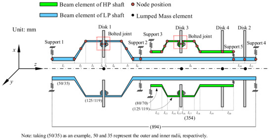
Figure 1.
Finite element model of a dual-rotor system with bolted joints.
2.1. Dual-Rotor System Model
The dual-rotor system is modeled by Timoshenko beam elements. The finite element model includes 24 beam elements. The disks and bearings are simplified as lumped mass elements and spring-damping elements, respectively. The bolted joint is a noncontinuous structure; thus, the beam elements near the bolted joint structures are connected by the joint elements.
The generalized displacement vectors of the LP rotor can be expressed as follows:
where x1, y1,⋯, x15, y15 are translations of nodes 1−15, and θx1, θy1,⋯, θx15, θy15 are rotations of nodes 1−15.
The LP rotor can be described in matrix form as follows:
where Ω is the rotating speed. M, C, G, and K are the mass, damping, gyroscopic, and stiffness matrices. The subscript L represents the index of the LP rotor. Rayleigh damping is applied, and the damping matrix is given as CL = αML + βKL.
The generalized force vectors of the LP rotor can be described as
where m and e denote the mass and eccentricity, and the subscript represents the number of disks.
The generalized displacement vectors of the HP rotor are described as follows:
Accordingly, the motion equation of the HP rotor can be obtained:
where the subscript H denotes the index of the HP rotor.
The force of the HP rotor is expressed as follows:
Consider the eccentricity of all disks, and the eccentricity is 0.5 mm. Then, the motion equation of the dual-rotor system is further written as follows:
Next, the stiffness of supports needs to be added to the stiffness matric of dual-rotor system, where the positions are K(1,1), K(2,2), K(45,45), K(46,46), K(57,57), K(58,58), K(61,61), and K(62,62). Damping is added in the same way. The stiffness of the intershaft bearing is added as follows:
where k = 13 and l = 28.
2.2. Bolted Joint Model
The bolted joint is considered as a joint element with two nodes. One of the nodes is located at the end of the flange near the disk, and the other node is located at the position of the disk, as shown in Figure 2. The generalized displacement vectors and stiffness matrix are expressed as follows:
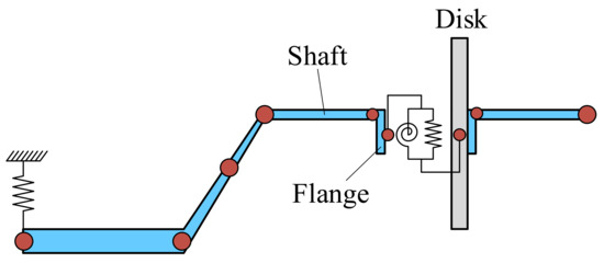
Figure 2.
Schematic diagram of the bolted joint model.
In terms of [6,37,38], the stiffness of the bolted joint has piecewise linear characteristics, and the critical point occurs when the external force is equal to the effect of preload applied on the bolts. The first and second stages of piecewise linear characteristics are depicted in Figure 3a,b, respectively.
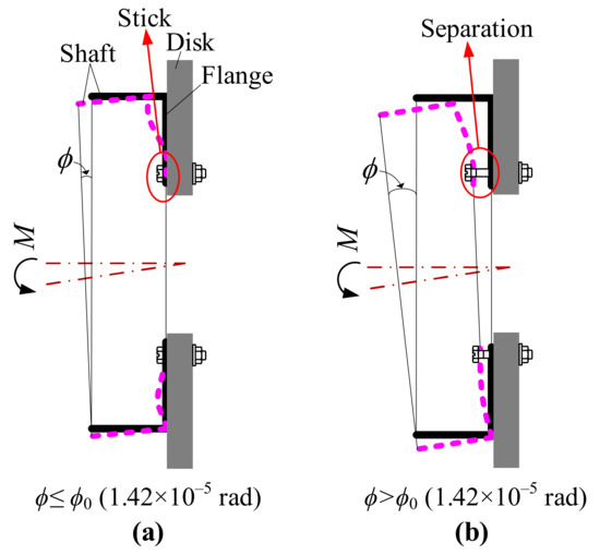
Figure 3.
Schematic diagram for the deformation of the bolted joint under a bending moment: (a) stick state; (b) separation state.
The stiffness characteristics of bolted joint in [37] are expressed as
where ϕ is the relative rotation angle between the flange and disk and is shown in Figure 3. ϕ0 is the critical rotation angle when the external force is equal to the effect of preload applied on the bolts. kθ1 and kθ2 are the stiffness at the first and second stages, respectively. ϕ can be obtained as follows:
where the subscripts J and J + 1 represent the left and right nodes of the joint element, respectively. The stiffness and critical rotation angle can be calculated according to [37] and are listed in Table 1. More detailed formulas can be found in [37].

Table 1.
Stiffness and critical rotation angle of bolted joints.
2.3. Convergence Analysis
In this section, the influence of node number on the vibration responses is assessed. The element number is chosen as 24, 36, and 48. The amplitude frequency responses for 24, 36, and 48 elements are shown in Figure 4, and the spectrum cascades under different rotating speeds are illustrated in Figure 5. It is found that the amplitude frequency responses and spectrum cascades for the cases of 24, 36, and 48 elements are almost identical. The vibration responses have already converged. Therefore, the case of 24 elements is used in the following analysis.
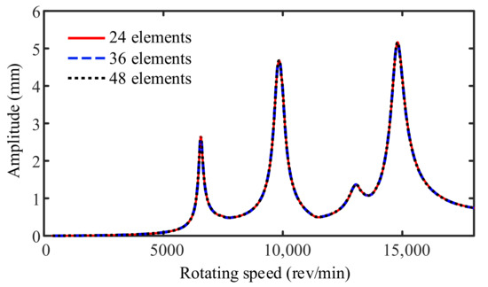
Figure 4.
Amplitude frequency responses for 24, 36, and 48 elements.
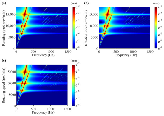
Figure 5.
Spectrum cascades: (a) 24 elements; (b) 36 elements; (c) 48 elements.
2.4. Comparison of the Dual-Rotor System with and without Bolted Joints
The bolted joint changes the local stiffness of the rotor system subjected to a heavy load, which further influences the vibration behaviors of the rotor system [5,6]. Thus, the section aims at investigating the effect of bolted joints and further verifying the bolted joint model.
The dual-rotor system models with and without bolted joints are established to compare the vibration characteristics of these two models. The configurations of the models with and without bolted joints are the same except for the parameters of the bolted joints. Note that the positions of bolted joints are continuous structures in the model without bolted joints. The dynamic equations of these two models are obtained by the Newmark method. The ratio of rotational speed (R = ΩH/ΩL) is 1.5 [39] in this paper. The amplitude frequency responses of disk 1 of the two models are presented in Figure 6. The time responses at resonance of these two models are shown in Figure 7. It can be seen that the critical speeds of the model with bolted joints are less than those of the model without bolted joints. Thus, the bolted joints reduce the critical speed of the rotor system since they change the local stiffness, which is consistent with the laws in [37]. In addition, the spectrum cascades under different rotating speeds of these two models are shown in Figure 8. Only the fundamental frequencies of LP and HP rotors are prominent in the spectrum cascades of the model without bolted joints (see Figure 8b). As a contrast, for the model with bolted joints, the frequency multiplication of LP and HP rotors (2fL, 3fL, 4fL, 2fH, 3fH, and 4fH) has occurred, which is consistent with the results of [40]. Thus, the bolted joint model is considered verified, and the bolted joints must be considered in developing scaling relationships due to the significant influence on the rotor system.
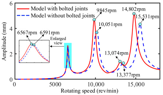
Figure 6.
Comparison of the amplitude frequency responses between the models with and without bolted joints.
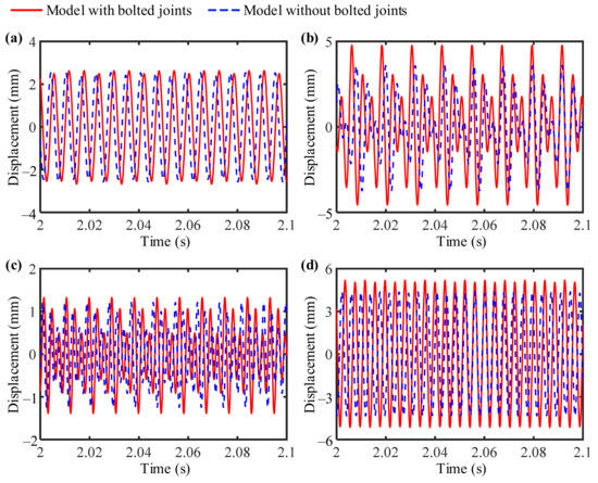
Figure 7.
Time responses between the models with and without bolted joints: (a) 6567 and 6591 rpm; (b) 9845 and 10,051 rpm; (c) 13,074 and 13,377 rpm; (d) 14,802 and 15,531 rpm.
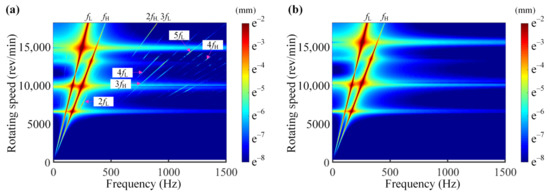
Figure 8.
Spectrum cascades: (a) model with bolted joints; (b) model without bolted joints.
3. Scaling Relationships for the Dual-Rotor System with Bolted Joints
In terms of STAGE and EM, the governing equation or a certain work of derivation is required, which is not available for the complex structure. Aiming at these issues, the scaling relationships are obtained by generalized and fundamental equations, rather than the governing equation of the whole structure. The schematic diagram is shown in Figure 9. Furthermore, developing scaling relationships from generalized and fundamental equations reduces the calculation effort. As for the dual-rotor system, nonlinearity is introduced by bolted joints. The parameters of the bolt joints need to be put into similitude appropriately to obtain exact results.
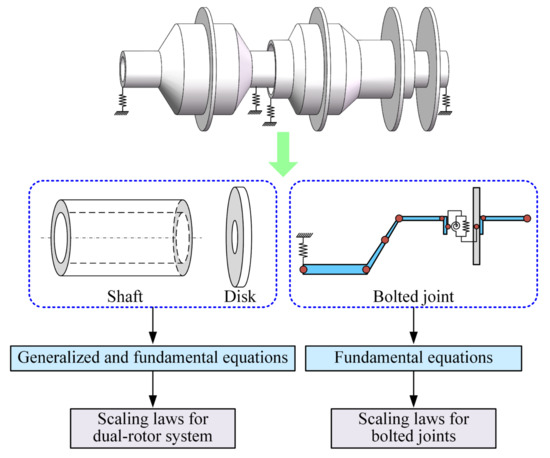
Figure 9.
Schematic diagram of deriving scaling relationships.
3.1. Scaling Relationships for Dual-Rotor System
The generalized translational equation of rigid disks is expressed as
where ρd, ld, and rd are the density, thickness, and radius of the disks.
The generalized translational equation of a shaft element can be written as
Where ρs, ls, rs, cs, ks, and xs are the density, length, radius, damping, stiffness, and displacement in the x-direction of a shaft element.
The internal bending moment of the shaft can be written as
where E and I are Young’s modulus and area moment of inertia, respectively.
The internal bending moment M can be also expressed as
Substituting Equations (15) and (16) into Equation (14) yields
According to the continuity of displacements,
Herein, the scaling factor λ is the prototype parameter divided by the model parameter. A parameter is written in the subscript of scaling factor λ, which indicates the scaling factor of the parameter. Then, applying similitude theory to Equations (13) and (17) yields
Here, the geometric parameters of the dual-rotor system are scaled by the same ratio; i.e., λr = λl. The following scaling relationships are obtained by Equation (19) and λΩ = 1/λt:
According to dimensional analysis [30], the parameters with the same unit can be scaled by the same scaling factor. Thus, the scaling factors of supports’ stiffness and damping are equal to those of shaft; i.e., λk and λc represent the scaling factors for the stiffness and damping of both shaft and supports.
The forces on the intershaft support can be expressed as follows:
where kin is the stiffness of the intershaft support, and xL and xH are the displacements of LP and HP rotors, respectively. Q is the shear force.
Applying similitude theory to Equation (24) yields
In terms of Equations (25) and (26), the following scaling relationships can be obtained:
It is found from Equation (27) that the scaling factor of intershaft support stiffness λkin is equal to that of the shaft stiffness λk. According to Equation (28), the scaling factors of displacements can be represented by scaling factor λx.
3.2. Scaling Relationships for Bolted Joints
In this section, the scaling relationships related to the bolt joint parameters and rotor system parameters are developed. Nonlinearity is introduced by the piecewise linear stiffness of bolted joints. Therefore, the stiffness of bolted joints needs to be put into similitude first.
The piecewise linear stiffness is the angular stiffness; thus, the angular stiffness can be expressed as
where kθ is the piecewise linear stiffness, which includes kθ1 and kθ2. ϕ is the deflection angle of the bolted joints, which is dimensionless.
According to Equations (15), (23), and (29), the scaling factor for the piecewise linear stiffness can be obtained:
4. Verification of the Scaling Relationships
Two scaled models are studied and are named M1 and M2. The scaling factors of the models are listed in Table 2. Columns 2–4 of Table 2 are artificially determined scaling factors. The other scaling factors in Table 2 are obtained according to Equations (20)–(23) and (30). The parameters of the prototype are listed in Table A1 and Table A2, and the prototype is made of titanium alloy. The model M1 is a complete similitude model and the material is consistent with the prototype (titanium alloy). Furthermore, the material of M2 is carbon steel (density: 7850 kg/m3, Young’s modulus: 210 GPa, Poisson ratio: 0.26), which is different from M1. The purpose of M2 is to demonstrate the effectiveness of the proposed scaling relationships for the problem of different materials (between prototype and model). Note that M2 further reduces the costs of model testing since it allows for replacing the prototype with a model made of cheaper material. The sketches of the models and the prototype are presented in Figure 10.
Table 2.
The scaling factors of the models M1 and M2.
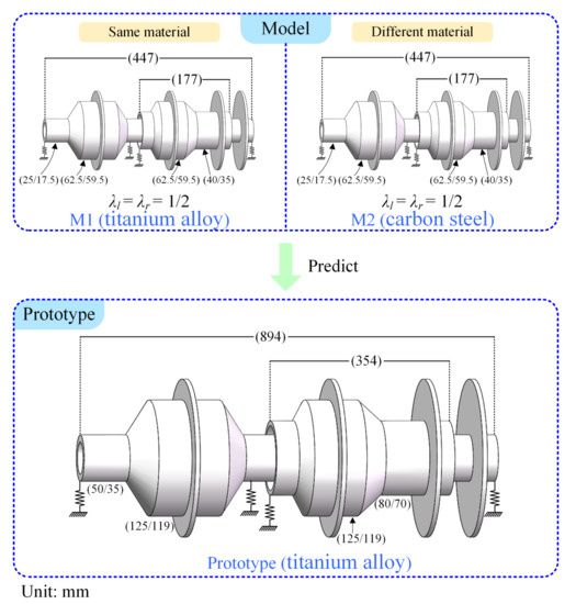
Figure 10.
Scheme of models and prototype.
Aiming at the working condition and structural characteristics of dual-rotor systems, LP rotor excitation (Section 4.1), HP rotor excitation (Section 4.2), two frequency excitations (Section 4.3), and counter-rotation (Section 4.4) are considered in predicting the vibration characteristics.
4.1. Case 1: LP Rotor Excitation
LP rotor excitation represents that disk 1 and disk 2 have mass eccentricities. Figure 8 presents the vibration responses of disk 1 of the prototype, the prediction as well as unscaled results. The aim is to predict the responses of the prototype (red line in Figure 11) by using the responses of models (dotted line in Figure 8). The dotted lines labeled as “unscaled” are the responses of models M1 and M2. The abscissa of the model’s response is multiplied by λω (see Table 2), and the ordinate is multiplied by λx. Then, the prediction results (circles and points in Figure 11) can be obtained and are compared with the results of the prototype. It can be seen from Figure 11 that the unscaled results differ greatly from the results of the prototype. After prediction, the amplitude frequency responses (AFRs) of the prototype and predicted results overlap perfectly. It is worth noting that M2 is beneficial to further reduce the test cost since it is not only reduced in size but also relatively cheap in material (compared to the prototype).
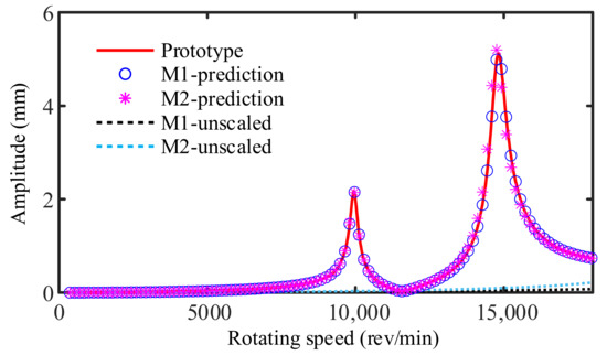
Figure 11.
Prediction of AFR from M1 and M2 under LP rotor excitation.
Figure 12 presents the spectrum cascades under different rotating speeds of the prototype and corresponding predicted results for models M1 and M2. The frequency components of the prototype are made up of the frequency multiplication, such as 2fL, 3fL, 4fL, and 5fL, which is consistent with the laws in [40]. The results of models M1 and M2 are consistent with those of the prototype. This indicates that both the models M1 and M2 can accurately reproduce the frequency components of the prototype, even though M2 is made of relatively cheap material.
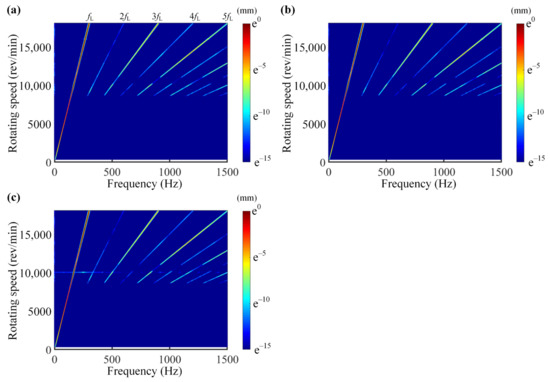
Figure 12.
Spectrum cascades of (a) prototype and the prediction results from the models (b) M1 and (c) M2 under LP rotor excitation.
4.2. Case 2: HP Rotor Excitation
HP rotor excitation means that disk 3 and disk 4 have mass eccentricities. Figure 13 and Figure 14 show the predicted results for the amplitude frequency responses and spectrum cascades, respectively. It is found that the vibration responses of the prototype can also be predicted accurately by the models M1 and M2, where different materials between the prototype and models are considered in the similitude procedure. In addition, the frequency components (2fL, 3fL, 4fL, and 5fL) of the prototype can also be predicted by the two models under HP rotor excitation.
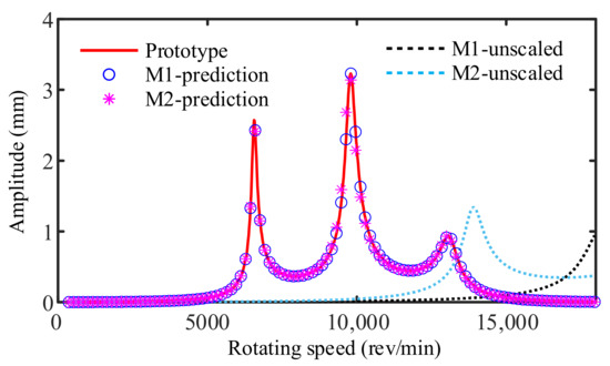
Figure 13.
Prediction of AFR from M1 and M2 under HP rotor excitation.
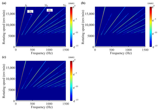
Figure 14.
Spectrum cascades of (a) prototype and the prediction results from the models (b) M1 and (c) M2 under HP rotor excitation.
4.3. Case 3: Two Frequency Excitations
Two frequency excitations mean that all disks of LP and HP rotors have mass eccentricities. Figure 15 and Figure 16 describe the predicted results of the amplitude frequency responses and frequency components in the case of two frequency excitations. The vibration responses of M1 and M2 agree well with those of the prototype. Besides, the frequency components of the two models match perfectly those of the prototype.
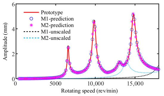
Figure 15.
Prediction of AFR from M1 and M2 under two frequency excitations.
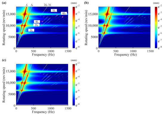
Figure 16.
Spectrum cascades of (a) prototype and the prediction results from the models (b) M1 and (c) M2 under two frequency excitations.
4.4. Case 4: Counter-Rotation
Co- and counter-rotation indicate that the LP rotor and HP rotor rotate in the same and opposite directions, respectively. Cases 1–3 are investigated in the case of corotation; thus, counter-rotation is considered. The case of two frequency excitations is taken as an example in this section. The predictions for amplitude frequency responses and spectrum cascades are shown in Figure 17 and Figure 18. The predicted results show exact agreement between the models M1 and M2 and the prototype. Thus, the accuracy and effectiveness of proposed scaling relationships are considered verified.
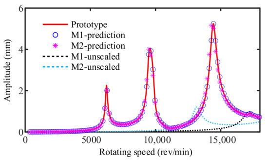
Figure 17.
Prediction of AFR from M1 and M2 under counter-rotation.
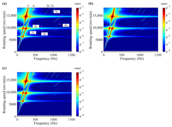
Figure 18.
Spectrum cascades of (a) prototype and the prediction results from the models (b) M1 and (c) M2 under counter-rotation.
5. Conclusions
This paper presents the scaling relationships for predicting the dynamic characteristics of a dual-rotor system with bolted joints, where different materials between the prototype and models are taken into account. The effects of bolted joints on the dual-rotor system are investigated, and the results indicate that bolted joints should be considered in the similitude procedure. The scaling relationships are obtained by generalized and fundamental equations and are used to predict the critical speeds, vibration responses, and frequency components under different working conditions. The main findings are summarized as follows:
- The scaling relationships are developed by generalized and fundamental equations of substructures (shaft, disk, and bolted joint). The scaling factors of geometric dimensions, support parameters, critical speed, and vibration displacement are derived and can be used to design scaled models. However, as for STAGE and EM, the governing equations of the whole structure are required when deriving scaling relationships. Thus, the scaling relationships developed in this paper can reduce the calculation effort and provide the possibility for the application of complex structures.
- The effect of bolted joints on the dual-rotor system is considered. It is found that the bolted joints reduce the critical speed and lead to the emergence of frequency multiplication. Thus, the bolted joints need to be considered in similitude analysis. Aiming at this issue, the scaling relationships derived in this paper take the nonlinear stiffness of bolted joint into account for the first time.
- For the case of LP rotor excitation or HP rotor excitation, only the resonance and frequency components of the LP rotor or HP rotor can be found. As for two frequency excitations, both the resonance and frequency components of LP and HP rotors can be observed. Besides, the critical speeds decrease slightly under the case of counter-rotation. The predicted results of scaled models are compared with the results of the prototype in these cases. The results for all working conditions show that the derived scaling relationships can accurately predict the critical speeds, vibration responses, and frequency components of the prototype, even though different materials and the nonlinearity introduced by bolted joints are considered.
In our future work, the case of the shaft, disk, and bearings being made of different materials will be investigated and more emphasis will be placed on the experimental verification.
Author Contributions
Conceptualization, L.L. and Z.L.; methodology, L.L.; software, L.L. and F.H.; validation, L.L. and Z.Q.; formal analysis, Y.L.; investigation, L.L.; data curation, F.H.; writing—original draft preparation, L.L.; writing—review and editing, Z.L.; visualization, Z.Q. and X.Y.; supervision, Z.L.; project administration, Z.L.; funding acquisition, Z.L. All authors have read and agreed to the published version of the manuscript.
Funding
This research was funded by the National Science Foundation of China, grant numbers 11872148 and U1908217; the Fundamental Research Funds for the Central Universities of China, grant numbers N180703018, N2003012, and N2003013; and the Joint Foundation of Basic and Applied Basic Research of Guangdong Province, grant number 2020B1515120015.
Institutional Review Board Statement
Not applicable.
Informed Consent Statement
Not applicable.
Data Availability Statement
The data in the paper can be requested by email to the corresponding author.
Conflicts of Interest
The authors declare no conflict of interest.
Nomenclature
| Roman symbols | |
| CH, CL | damping matrices of HP and LP rotors |
| cs, ks | damping and stiffness of shaft |
| E | Young’s modulus of shaft |
| e1-4 | eccentricities of disks 1–4 |
| fH, fL | rotating frequencies of HP and LP rotors |
| GH, GL | gyroscopic matrices of HP and LP rotors |
| g | gravitational acceleration |
| I | area moment of inertia of shaft |
| k, l | node numbers of the intershaft support |
| kθ1, kθ2 | stiffness of bolted joint at the first and second stages |
| kin | stiffness matrix of the intershaft support |
| KH, KL | stiffness matrices of HP and LP rotors |
| KJ | stiffness matrix of joint element |
| ld, ls | thickness of disk and length of shaft |
| M | internal bending moment of shaft |
| MH, ML | mass matrices of HP and LP rotors |
| m1-4 | mass of disks 1–4 |
| Q | shear force |
| QH, QL | force vectors of high- and low-pressure rotors |
| qJ | generalized displacement vector of joint element |
| R | ratio of rotational speed between HP and LP rotors |
| rd, rs | radii of disk and shaft |
| rLi, rLo | inner and outer radii of left end of shaft element |
| rRi, rRo | inner and outer radii of right end of shaft element |
| t | time |
| uH, uL | displacement vectors of HP and LP rotors |
| x1-28, y1-28 | displacements of nodes 1–28 in x and y directions |
| xJ, yJ | displacements of joint element in x and y directions |
| xd, ys | displacements of disk and shaft |
| Greek symbols | |
| θx1-28, θy1-28 | rotations of nodes 1–28 in x and y directions |
| θxJ, θyJ | rotations of joint element in x and y directions |
| λρ, λE | scaling factors of density and Young’s modulus |
| λl, λr, λe | scaling factors of length, radius, and eccentricity |
| λω, λΩ, λt, λx | scaling factors of critical speed, rotating speed, time, and displacement |
| λxH, λxL | scaling factors of displacement of HP and LP rotors |
| λk, λc, λkθ | scaling factors of support stiffness, damping, and bolted joint stiffness |
| λkin | scaling factor of stiffness of intershaft support |
| ρd, ρs | densities of disk and shaft |
| ϕ0, ϕ | critical rotation angle and relative rotation angle between the flange and disk |
| ΩH, ΩL | rotating speeds of HP and LP rotors |
Appendix A
Table A1.
Dimensions of the dual-rotor system.
Table A1.
Dimensions of the dual-rotor system.
| Parameter (m) | Value | Parameter (m) | Value | |||
|---|---|---|---|---|---|---|
| rLi | rLo | rRi | rRo | |||
| Length of shaft element l1 | 0.100 | Radii of shaft element l1 | 0.035 | 0.050 | 0.035 | 0.050 |
| Length of shaft element l2 | 0.050 | Radii of shaft element l2 | 0.035 | 0.050 | 0.119 | 0.125 |
| Length of shaft element l3, l6 | 0.070 | Radii of shaft element l3, l6 | 0.119 | 0.125 | 0.119 | 0.125 |
| Length of shaft element l4, l5 | 0.002 | Radii of shaft element l4, l5 | 0.105 | 0.125 | 0.105 | 0.125 |
| Length of shaft element l7 | 0.050 | Radii of shaft element l7 | 0.119 | 0.125 | 0.035 | 0.050 |
| Length of shaft element l8, l10, l11 | 0.050 | Radii of shaft element l8, l10, l11 | 0.035 | 0.050 | 0.035 | 0.050 |
| Length of shaft element l9 | 0.400 | Radii of shaft element l9 | 0.035 | 0.050 | 0.035 | 0.050 |
| Length of shaft element l12, l20 | 0.050 | Radii of shaft element l12, l20 | 0.070 | 0.080 | 0.070 | 0.080 |
| Length of shaft element l13 | 0.025 | Radii of shaft element l13 | 0.070 | 0.080 | 0.119 | 0.125 |
| Length of shaft element l14, l17 | 0.050 | Radii of shaft element l14, l17 | 0.119 | 0.125 | 0.119 | 0.125 |
| Length of shaft element l15, l16 | 0.002 | Radii of shaft element l15, l16 | 0.105 | 0.125 | 0.105 | 0.125 |
| Length of shaft element l18 | 0.025 | Radii of shaft element l18 | 0.119 | 0.125 | 0.070 | 0.080 |
| Length of shaft element l19 | 0.100 | Radii of shaft element l19 | 0.070 | 0.080 | 0.070 | 0.080 |
Table A2.
Physical parameters of the dual-rotor system.
Table A2.
Physical parameters of the dual-rotor system.
| Parameter (m) | Value | Parameter (m) | Value |
|---|---|---|---|
| Mass of disks 1 and 2 (kg) | 7.22 | Moment of inertia of disks 1 and 2 (kg.m2) | 0.11 |
| Mass of disk 3 (kg) | 6.56 | Moment of inertia of disk 3 (kg.m2) | 0.11 |
| Mass of disk 4 (kg) | 6.15 | Moment of inertia of disk 4 (kg.m2) | 0.11 |
| Support stiffness k1, k2, k3, k4 (N/m) | 2 × 10⁷ | Support damping c1, c2, c3, c4, c5 (N/m) | 500 |
| Support stiffness kin (N/m) | 4 × 10⁷ | Density (kg/m3) | 4350 |
| Elastic modulus (GPa) | 105 | Poisson ratio | 0.26 |
References
- Yu, P.C.; Zhang, D.Y.; Ma, Y.H.; Hong, J. Dynamic modeling and vibration characteristics analysis of the aero-engine dual-rotor system with Fan blade out. Mech. Syst. Sig. Process. 2018, 106, 158–175. [Google Scholar] [CrossRef]
- Wang, N.F.; Jiang, D.X. Vibration response characteristics of a dual-rotor with unbalance-misalignment coupling faults: Theoretical analysis and experimental study. Mech. Mach. Theory 2018, 125, 207–219. [Google Scholar] [CrossRef]
- Sun, G.; Palazzolo, A.; Provenza, A.; Lawrence, C.; Carney, K. Long duration blade loss simulations including thermal growths for dual-rotor gas turbine engine. J. Sound Vib. 2008, 316, 147–163. [Google Scholar] [CrossRef]
- Bab, S.; Najafi, M.; Fathi Sola, J.; Abbasi, A. Annihilation of non-stationary vibration of a gas turbine rotor system under rub-impact effect using a nonlinear absorber. Mech. Mach. Theory 2019, 139, 379–406. [Google Scholar] [CrossRef]
- Hong, J.; Chen, X.Q.; Wang, Y.F.; Ma, Y.H. Optimization of dynamics of non-continuous rotor based on model of rotor stiffness. Mech. Syst. Sig. Process. 2019, 131, 166–182. [Google Scholar] [CrossRef]
- Liu, S.G.; Ma, Y.H.; Zhang, D.Y.; Hong, J. Studies on dynamic characteristics of the joint in the aero-engine rotor system. Mech. Syst. Sig. Process. 2012, 29, 120–136. [Google Scholar] [CrossRef]
- Asl, M.E.; Niezrecki, C.; Sherwood, J.; Avitabile, P. Vibration prediction of thin-walled composite I-beams using scaled models. Thin Walled Struct. 2017, 113, 151–161. [Google Scholar] [CrossRef] [Green Version]
- Asl, M.E.; Niezrecki, C.; Sherwood, J.; Avitabile, P. Experimental and theoretical similitude analysis for flexural bending of scaled-down laminated I-beams. Compos. Struct. 2017, 176, 812–822. [Google Scholar] [CrossRef]
- Kasivitamnuay, J.; Singhatanadgid, P. Scaling laws for displacement of elastic beam by energy method. Int. J. Mech. Sci. 2017, 128, 361–367. [Google Scholar] [CrossRef]
- Kasivitamnuay, J.; Singhatanadgid, P. Scaling laws for static displacement of linearly elastic cracked beam by energy method. Theor. Appl. Fract. Mech. 2018, 98, 157–166. [Google Scholar] [CrossRef]
- Coutinho, C.P.; Baptista, A.J.; Rodriges, J.D. Modular approach to structural similitude. Int. J. Mech. Sci. 2018, 135, 294–312. [Google Scholar] [CrossRef]
- Yazdi, A.A. Study nonlinear vibration of cross- ply laminated plates using scale models. Polym. Composite. 2014, 35, 752–758. [Google Scholar] [CrossRef]
- Rezaeepazhand, J.; Yazdi, A.A. Similitude requirements and scaling laws for flutter prediction of angle-ply composite plates. Compos. Part B: Eng. 2011, 42, 51–56. [Google Scholar] [CrossRef]
- Frostig, Y.; Simitses, G.J. Similitude of sandwich panels with a soft core in buckling. Compos. Part B: Eng. 2004, 35, 599–608. [Google Scholar] [CrossRef]
- Singhatanadgid, P.; Songkhla, A.N. An experimental investigation into the use of scaling laws for predicting vibration responses of rectangular thin plates. J. Sound Vib. 2008, 311, 314–327. [Google Scholar] [CrossRef]
- De Rosa, S.; Franco, F. A scaling procedure for the response of an isolated system with high modal overlap factor. Mech. Syst. Sig. Process. 2008, 22, 1549–1565. [Google Scholar] [CrossRef]
- Franco, F.; Robin, O.; Ciappi, E.; De Rosa, S.; Berry, A.; Petrone, G. Similitude laws for the structural response of flat plates under a turbulent boundary layer excitation. Mech. Syst. Sig. Process. 2019, 129, 590–613. [Google Scholar] [CrossRef]
- Mazzariol, L.M.; Alves, M. Similarity laws of structures under impact load: Geometric and material distortion. Int. J. Mech. Sci. 2019, 157, 633–647. [Google Scholar] [CrossRef]
- Petrone, G.; Manfredonia, M.; De Rosa, S.; Franco, F. Structural similitudes of stiffened cylinders. Math. Mech. Solids 2019, 24, 527–541. [Google Scholar] [CrossRef]
- Rezaeepazhand, J.; Simitses, G.J.; Starnes, J.H. Design of scaled down models for predicting shell vibration response. J. Sound Vib. 1996, 195, 301–311. [Google Scholar] [CrossRef]
- Rezaeepazhand, J.; Simitses, G.J.; Starnes, J.H. Scale models for laminated cylindrical shells subjected to axial compression. Compos. Struct. 1996, 34, 371–379. [Google Scholar] [CrossRef]
- Ungbhakorn, V.; Wattanasakulpong, N. Structural similitude and scaling laws of anti-symmetric cross-ply laminated cylindrical shells for buckling and vibration experiments. Int. J. Struct. Stab. Dyn. 2007, 7, 609–627. [Google Scholar] [CrossRef]
- De Rosa, S.; Franco, F.; Polito, T. Structural similitudes for the dynamic response of plates and assemblies of plates. Mech. Syst. Sig. Process. 2011, 25, 969–980. [Google Scholar] [CrossRef]
- De Rosa, S.; Franco, F. On the use of the asymptotic scaled modal analysis for time-harmonic structural analysis and for the prediction of coupling loss factors for similar systems. Mech. Syst. Sig. Process. 2010, 24, 455–480. [Google Scholar] [CrossRef]
- De Rosa, S.; Franco, F.; Polito, T. Partial scaling of finite element models for the analysis of the coupling between short and long structural wavelengths. Mech. Syst. Sig. Process. 2015, 52–53, 722–740. [Google Scholar] [CrossRef]
- You, C.; Yasaee, M.; Dayyani, I. Structural similitude design for a scaled composite wing box based on optimised stacking sequence. Compos. Struct. 2019, 226, 111255. [Google Scholar] [CrossRef]
- Song, Y.Y.; Wu, J.; Yu, G.; Huang, T. Dynamic characteristic prediction of a 5-DOF hybrid machine tool by using scale model considering the geometric distortion of bearings. Mech. Mach. Theory 2020, 145, 103679. [Google Scholar] [CrossRef]
- Wu, J.J. Prediction of lateral vibration characteristics of a full-size rotor-bearing system by using those of its scale models. Finite Elem. Anal. Des. 2007, 43, 803–816. [Google Scholar] [CrossRef]
- Li, L.; Luo, Z.; He, F.X.; Sun, K.; Yan, X.L. An improved partial similitude method for dynamic characteristic of rotor systems based on Levenberg–Marquardt method. Mech. Syst. Sig. Process. 2022, 165, 108405. [Google Scholar] [CrossRef]
- Casaburo, A.; Petrone, G.; Franco, F.; De Rosa, S. A review of similitude methods for structural engineering. Appl. Mech. Rev. 2019, 71, 30802. [Google Scholar] [CrossRef] [Green Version]
- Rezaeepazhand, J.; Simitses, G.J.; Starnes, J.H. Use of scaled-down models for predicting vibration response of laminated plates. Compos. Struct. 1995, 30, 419–426. [Google Scholar] [CrossRef]
- Yazdi, A.A.; Rezaeepazhand, J. Structural similitude for flutter of delaminated composite beam-plates. Compos. Struct. 2011, 93, 1918–1922. [Google Scholar] [CrossRef]
- Ungbhakorn, V.; Singhatanadgid, P. A scaling law for vibration response of laminated doubly curved shallow shells by energy approach. Mech. Adv. Mater. Struc. 2009, 16, 333–344. [Google Scholar] [CrossRef]
- De Rosa, S.; Franco, F.; Li, X.; Polito, T. A similitude for structural acoustic enclosures. Mech. Syst. Sig. Process. 2012, 30, 330–342. [Google Scholar] [CrossRef]
- De Rosa, S.; Franco, F.; Meruane, V. Similitudes for the structural response of flexural plates. Proc. IMechE Part C J. Mech. Eng. Sci. 2016, 230, 174–188. [Google Scholar] [CrossRef] [Green Version]
- Adams, C.; Bos, J.; Slomski, E.M.; Melz, T. Scaling laws obtained from a sensitivity analysis and applied to thin vibrating structures. Mech. Syst. Sig. Process. 2018, 110, 590–610. [Google Scholar] [CrossRef]
- Qin, Z.Y.; Han, Q.K.; Chu, F.L. Analytical model of bolted disk–drum joints and its application to dynamic analysis of jointed rotor. Proc. IMechE Part C J. Mech. Eng. Sci. 2014, 228, 646–663. [Google Scholar] [CrossRef]
- Li, Y.Q.; Luo, Z.; Liu, J.X.; Ma, H.; Yang, D.S. Dynamic modeling and stability analysis of a rotor-bearing system with bolted-disk joint. Mech. Syst. Sig. Process. 2021, 158, 107778. [Google Scholar] [CrossRef]
- Shanmugam, A.; Padmanabhan, C. A fixed–free interface component mode synthesis method for rotordynamic analysis. J. Sound Vib. 2006, 297, 664–679. [Google Scholar] [CrossRef]
- Li, C.F.; Qiao, R.H.; Tang, Q.S.; Miao, X.Y. Investigation on the vibration and interface state of a thin-walled cylindrical shell with bolted joints considering its bilinear stiffness. Appl. Acoust. 2021, 172, 107580. [Google Scholar] [CrossRef]
Publisher’s Note: MDPI stays neutral with regard to jurisdictional claims in published maps and institutional affiliations. |
© 2021 by the authors. Licensee MDPI, Basel, Switzerland. This article is an open access article distributed under the terms and conditions of the Creative Commons Attribution (CC BY) license (https://creativecommons.org/licenses/by/4.0/).