Abstract
This paper explores a novel single tail tilt servomotor tri-rotor ducted vertical takeoff and landing unmanned aerial vehicle system (VTOL-UAV), and proposes a compound control method combining disturbance observer, model predictive control (MPC) and sliding mode nonlinear dynamic inversion (NDI), and realizes the robust tracking control of the VTOL-UAV trajectory under compound disturbance. Specifically, the inner loop adopts nonlinear dynamic inverse which improved by sliding mode to realize the pseudo linearization of the system. The outer loop adopts the model predictive control based on the E-SSPC (State Space Predictive Controller based on the Error model) method, on this basis, the sliding mode disturbance observer based on fast Super-twisting algorithm is introduced into the position loop to observe and compensate the disturbance in real time, which improves the robustness of the outer loop system. Numerical simulation experiments verify the effectiveness and robustness of the control method. Finally, the flight test of the VTOL-UAV is carried out.
1. Introduction
Compound helicopter combines the advantages of vertical take-off, landing and hovering of helicopter, as well as the rapidity of fixed wing aircraft. It has broad application prospect and is one of the most important development directions of the helicopter. The Lockheed Martin Sikorsky-Boeing SB > 1 DEFIANT X helicopter exceeded 426 km/h (230 knots) in flight testing [1]. The Eurocopter X3 hybrid fixed wing helicopter opens the frontiers of aviation by attaining a speed milestone of 472 km/h (255 knots) in level flight, and reaches a speed of 487 km/h (263 knots) during a descent [2].
The compound helicopter has the characteristics of complex aerodynamic characteristics and multiple flight modes, so it is difficult to achieve the precision flight. There are many nonlinear control methods to solve the problem, such as gain scheduling, nonlinear dynamic inversion, backstepping, active disturbance rejection control, etc., each has its advantages and disadvantages. Different nonlinear control methods are combined to get better control effect than a single method. Reference [3] deduced the model of a compound helicopter, and predicted the maximum L/D (lift drag ratio) relation between the lift and propulsive force shares in different flight speeds and take-off weights, as well as rotor speed and blade twist. Reference [4] adopted the adaptive control to estimate and compensate the external disturbances to reduce the negative effects derived from actuator faults and input saturation, and a robust inner-outer loop adaptive FTC (Fault Tolerant Control) scheme improved by the backstepping was proposed to guarantee the tracking accuracy. Reference [5] divided the helicopter’s dynamic mode into the longitudinal-lateral and the heading-heave subsystem, and employed sliding mode control technique to compensate for the immeasurable flapping angles’ dynamic effects and external disturbances. In order to process the uncertainty and external disturbance of the longitudinal model of hypersonic vehicles, Reference [6] designed feedback linearization to realize the decoupling of the height and velocity channels, and applied nonlinear dynamic inverse control with the pole configuration method. Finally, sliding mode disturbance observer was used to estimate and compensate the equivalent disturbance. Reference [7] introduced extended state estimation algorithm with saturation constrainted observations to estimate the system disturbance and the system state. Via compensating the external disturbance and the coupling relationship among the system states, the active disturbance rejection controller was designed. Reference [8] proposed an improved piecewise constant adaptive NDI (Nonlinear Dynamic Inversion) control method suitable for general flight control systems, and gave the angular rates control strategy.
A novel tri-rotor ducted vertical takeoff and landing composite unmanned aerial vehicle system (Tri-Rotor Ducted VTOL-UAV) is developed by the authors, and it is equipped with a single tail tilt servomotor to delete the inverse torque and enhance controllability of yaw moment. The tri-rotor ducted VTOL-UAV is shown in the Figure 1. The two fronts of rotors rotate in opposite directions, which created reaction torque almost zero. The duct is applied to improve the efficiency of hovering and vertical flight, which is blended designed with wing body to reduce the resistance in forward flight. The working mode of the tail rotor tilt tri-rotor VTOL-UAV is as follows: it operates in helicopter mode when taking off and landing vertically, then the aircraft tilts forward and enters the low-speed forward flight state, when the flight speed increases to the transition threshold, the VTOL-UAV enters the conversion mode. When flying in airplane mode, the rotor system is locked out.
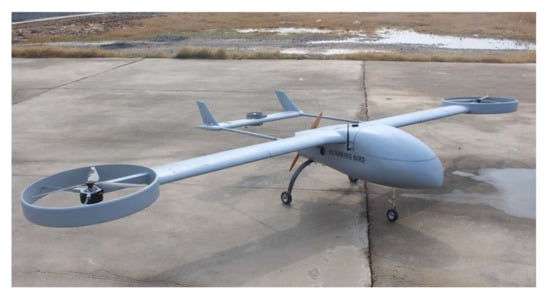
Figure 1.
The tail rotor tilting three ducted fan VTOL-UAV.
For the tri-rotor ducted VTOL-UAV, the aerodynamic characteristics are more complex than the compound UAV due to the effect of tilting tail, aerodynamic effects of ducts and rotors, three rotors instead of an even number of rotor, thus it is difficult to build an accurate model of the aircraft and obtain satisfactory flight accuracy through the conventional control method. Based on the relative independence of the inner and outer loops and the different requirements of response speed, the inner loop attitude controller and the outer loop position tracking controller are designed respectively. The dynamic inverse which can realize the pseudo linearization of nonlinear system by employing nonlinear cancellation has strong nonlinear processing ability [9]. Model predictive control (MPC) is suitable for slow varying systems, and has strong robustness and good control effect for position and speed control that has the characteristics of time delay, nonlinearity and uncertainty [10,11]. Therefore, a dual loop hierarchical compound control scheme which combines improved model predictive control and sliding mode nonlinear dynamic inversion (SMNDI) is proposed. The improved model predictive controller is designed for position control to provide the desired attitude command. For the attitude control, full state feedback on the angular motion model is carried out by using nonlinear dynamic inverse to counteract the nonlinear term, and a pseudo linear system with linear input and output relationship is obtained. However, there are some problems when combining model prediction with dynamic inversion, that is the dynamic inversion requires high-precision model, which also leads to insufficient robustness. The robustness of model predictive controller will be greatly challenged in the face of large disturbances. Because of the above problems and analysis, this paper introduces a sliding mode disturbance observer to observe and compensate the disturbance in real time, so as to strengthen the anti-interference of the position tracking controller [12,13].
2. Flight Dynamic Model
The motion equation of the tri-rotor ducted VTOL-UAV can be written as follows
where, and are the position and velocity in inertial frame respectively; m is the mass; ; g is the acceleration of gravity; is the transformation matrix from body coordinate frame to inertial frame,
is acceleration disturbance, which is caused by external force. is angular acceleration disturbance, which is caused by external torque. Both and are the unknown external bounded disturbances. is the attitude angle including roll angle, pitch angle and yaw angle. and is the attitude rate including roll rate, pitch rate and yaw rate. is the attitude vector transformation matrix,
is the total aerodynamic force acting on the aircraft, and is the resultant moment in body coordinate frame.
After obtaining the above equations, it is necessary to calculate the forces and moments that acting on the VTOL-UAV, which are shown in Figure 2. The total aerodynamic force acting on the aircraft including the and generated by the left and right rotors, the generated by the tilting tail rotor, the aerodynamic force acting on the fuselage , aerodynamic force on horizontal stabilizer and vertical fin . In addition, there is gravity on the aircraft .
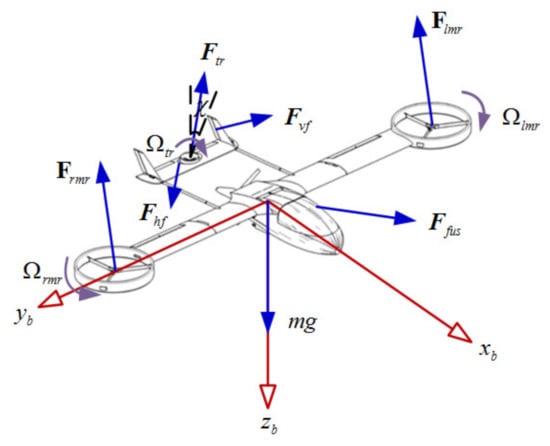
Figure 2.
The forces on the tri-rotor ducted VTOL-UAV.
For the ducted rotor system, the influence of the duct on rotors is reflected as follows [14]: the duct makes the air flow through the rotor more concentrated and stable, and the vortex loss at the blade tip is less and thus the efficiency of providing lift is higher. The duct is similar to an annular wing while vertical motion, which makes the internal air velocity greater than the external air velocity and generates additional lift. The calculation of the rotors with culvert is based on the vortex theory of the rotor in the axial flow created by Rukovsky [14,15]. Due to the mature calculation method of the rotor pull and torque, the calculation results are directly given,
where, T is the pull force of the rotor system. Q is the torque of the rotor system. A is rotor disk area. is Earth’s atmosphere density. is the attack angle of blade element. is the correction coefficient of the pull increment caused by the culvert [16,17]. represents the pull coefficient. is the blade drag coefficient. , and are the upstream infinite air flow velocity, the induced velocity and the downstream infinite air flow velocity respectively. is the increase of the vertical velocity at the downstream infinity compared with that at the upstream infinity. and are the horizontal velocity blocking coefficient of the air flow in the rotor plane due to the culvert and the retardation coefficient at the downstream infinity. is the local loss coefficient caused by the bending of the fluid at the culvert inlet. represents the dimensionless form of the vertical velocity component. represents the induced velocity at the rotor disc. is the rotor inflow ratio. is rotor solidity. R is rotor disc radius. is the blade rotation rate.
The influence of the wake generated by rotor blade rotation on the thrust propeller mainly depends on whether it is in the rotor downwash area [18]. Considering the influence of the culvert and the relative position of the rotor and propeller, there is the following conclusion: the aerodynamic interference between the culvert rotor and the propulsion propeller is small and can be ignored. Referring to the calculation method of rotor tension, the thrust and torque of propeller are respectively,
where, and are the flight velocity and the induced speed at the propeller disc; is the air velocity flowing through the propulsion propeller, which is superimposed by the flow velocity and induced velocity [19], and is the rotor pull.
The aerodynamic force of the fuselage is calculated by CFD method. The lift coefficient and drag coefficient with the attack angle are shown in Figure 3 and Figure 4 respectively. It can be seen that the lift coefficient has linear characteristics in the range of attack angle 0 to 10, and the lift line slope decreases when the attack angle is greater than 10. In order to ensure the safe flight of the aircraft, the attack angle should be controlled within 0 to 10.
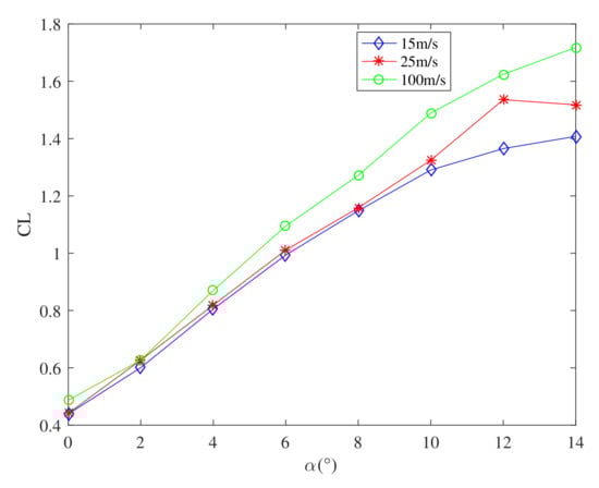
Figure 3.
The lift coefficient with attack angle of the fuselage.

Figure 4.
The drag coefficient with attack angle of the fuselage.
From the Figure 4, it can be seen that the drag coefficient has linear characteristics in the range of attack angle 0 to 12. Besides, the drag coefficient is a little large which leads to small lift drag ratio, because the aircraft drag is mainly generated by the culvert and the head of the aircraft, as shown in Figure 5, the points with large pressure of the whole aircraft are concentrated in the culvert and nose [20]. The aircraft resistance is small when it flies at a small rake angle, and resistance increases rapidly with the increase of flight speed. The aerodynamic shape of the aircraft is optimized to increase lift and reduce drag. The research result will be published in another paper.
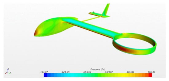
Figure 5.
The fuselage drag distribution of the tri-rotor ducted VTOL-UAV.
3. Controller Design
In this section, preliminaries of nonlinear dynamic inversion and model predictive control are introduced, and they will be further used in the analysis and design of control algorithm.
The tri-rotor ducted VTOL-UAV has obvious nonlinear characteristics caused by rotors and ducts, and the longitudinal-heading coupling is serious due to the left-right tilt of tail rotor. In addition, the influence of external disturbance needs to be considered. These factors bring great difficulties to the controller design. The combination of model predictive control and sliding mode dynamic inversion are used in this paper. The inner loop adopts the nonlinear dynamic inversion improved with the sliding mode idea to cancel the nonlinearity of the attitude and realize the pseudo linearization of the system, and the outer loop adopts the model predictive control based on the E-SSPC method. On this basis, the sliding mode disturbance observer based on fast super-twisting algorithm is introduced to observe the compound disturbance in the position loop, and the observed value compensates the original model predictive control law in real time, so as to improve the robustness and strengthen the anti-interference of the outer loop position control system. The complete UAV trajectory tracking hierarchical compound controller is shown in Figure 6 [20].
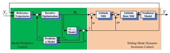
Figure 6.
The diagram of layered compound controller.
3.1. Attitude Dynamic Inverse Controller Design
In order to carry out the dynamic inverse control design, the attitude control system dynamic model in Equation (1) can be transformed into the following affine form [20]
where, , and are state matrices of attitude and attitude angle rate, , is the external unknown bounded disturbance.
where, , , are the moment of inertia about roll-axis, yaw-axis and pitch-axis respectively, and is cross moment of inertia about roll axis and pitch axis. Other physical meanings are the same as above.
According to the difference of response speed, the attitude subsystem can be divided into angle rate loop and attitude angle loop [21], and the control laws can be designed respectively.
3.1.1. Attitude Angle Rate Loop Controller Design
For the angle rate of UAV, the following form of sliding mode dynamic inverse control law can be designed
where, is an auxiliary variable; and are positive definite diagonal matrix; is the desired attitude angle rate, and it is given by the attitude angle sliding mode dynamic inverse controller; is control input of attitude angle rate control.
Theorem 1.
For attitude angle system (7), under the action of control law (10), the actual attitude angle rate ω will converge to the desired attitude angle rate asymptotically.
Proof.
Substituting the control law (10) to the system (7) to obtain
□
Selecting the Lyapunov candidate , both sides of is derivated, and substitute Equation (11) into it, there is
When selecting appropriate control parameter , it is easy to obtain . According to the BarbaLat lemma, because and are positive definite matrix, when t→∞, there is → 0, according to the definition of auxiliary variables , there is an convergence to asymptotically.
It can be seen from (12) that and have different functions, the is used to realize the asymptotic tracking of , while the is used for dealing with the uncertainty , their joint action ensures the balance of performance and robustness.
3.1.2. Attitude Angle Loop Controller Design
The attitude angle of the VTOL-UAV is an independent slowly varying state variable, the following form of sliding mode dynamic inverse controller can be designed
where, is an auxiliary variable; and are positive definite diagonal matrix; is the desired attitude angle, and it is given by the outer loop MPC position controller; is control input of attitude control.
3.2. Model Predictive Position Controller Design
3.2.1. Prediction Model
The prediction model is applied to the position control system. Considering the external bounded disturbance, the position subsystem can be written as follows
in which, is the external unknown bounded disturbance, meanings of the other variables are the same as above.
Now, suppose and as the new state varieties and control inputs, the (14) and (15) can be written as
The goal of position controller is to make the aircraft flight along the desired trajectory with as little error as possible under the action of control . The desired trajectory is designed as , and the error dynamics of the position subsystem can be obtained as
in which, , ,
At first, the uncertainty is not considered temporarily, and the backward difference is used to discretize the above Equation (17), supposing the discrete time step is , there is
where,
Let and are the predicted time length and the control time length respectively, and there is . Using Equation (17), through iteration and sorting, the expression of the system prediction model can be deduced as follows
where,
in which,
3.2.2. Optimal Control Law
Model predictive control is essentially an optimal control based on finite time domain. To obtain the optimal control law, the penalty function about the terminal state based on the traditional linear quadratic cost function is introduced
and the terminal state can be written as
where, , and it is the last row of the coefficient matrix H(t).
Therefore, the final objective cost function is defined as
where, is the predictive output of the vector ; and are the state weight matrix and the control weight matrix respectively. The optimal control law can be obtained by calculating the partial derivative of Equation (22) with respect to the control and making
The optimal control law is obtained by solving the Equation (23),
When the control sequence is obtained, the observed value of the uncertainty in (17) estimated by the sliding mode disturbance observer is introduced for compensation, and the final control law of the position subsystem is obtained
From the definition of control error , the desired control input can be obtained as
From the relationship between the control inputs and the forces, the desired , and can be obtained, which together serve as the desired command of attitude control and provide a reference command for the sliding mode dynamic inverse controller.
3.2.3. Sliding Mode Disturbance Observer Design
In order to effectively deal with the problem of insufficient robustness caused by external disturbance, and improve the control accuracy, the fast super-twisting algorithm is used to design the sliding mode disturbance observer to observe and estimate the external uncertainty continuously in real time [22,23,24,25,26]. The design of the sliding mode disturbance observer is as follows
where, is the auxiliary sliding mode vector, represents the sliding mode control input, and it is also the observation output of the disturbance, , , in which, each component is greater than zero, .
4. Numerical Simulation and Flight Test
4.1. Simulation
To verify the effectiveness of the control method, the numerical simulation is designed to test the trajectory tracking performance of the controller and its robustness to compound disturbances. Set the total simulation time as 30 s, and the reference trajectory expression for design tracking is
The initial position of the UAV is m, the initial velocity is m/s, other variables are set to zero. At the same time, compound disturbance is added into the velocity loop and angle rate loop respectively from the beginning of flight, and the disturbance expression is as follows
where, the units of and are m/s and rad/s respectively. The parameters of model prediction controller are as follows, prediction step , control step ; The state weight matrix and control weight matrix are , , the parameters of disturbance observer are , , , . The parameters of sliding mode dynamic inverse controller are , , , . The simulation result is shown in Figure 7, Figure 8, Figure 9 and Figure 10.
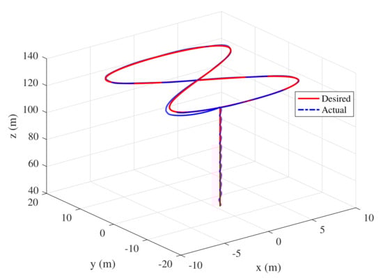
Figure 7.
The desired trajectory tracking.
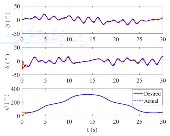
Figure 8.
The attitude angle response.
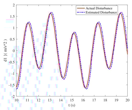
Figure 9.
The estimate of the composite disturbance d1.
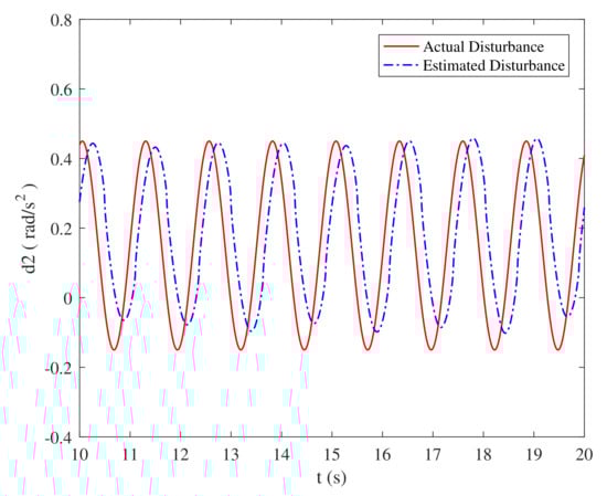
Figure 10.
The estimate of the composite disturbance d2.
The Figure 7 shows the tracking of the desired trajectory in three-dimensional space. It can be seen from the figure that the compound method proposed can realize the accurate tracking of the desired trajectory.
The Figure 8 shows the attitude angle and their tracking of the UAV when horizontal flight. The angle command is reasonable and tracking effect is ideal, the tracking error is small, which indicates that the sliding mode dynamic inverse method has strong robustness to compound disturbance.
Figure 9 and Figure 10 are the estimate of the composite disturbance and obtained by the sliding mode disturbance observer. It can be seen that the the desired and actual curves coincide basically, and the designed sliding mode disturbance observer has high tracking accuracy for composite disturbance. The observation and estimation of external disturbance has laid a foundation for disturbance compensation.
Figure 11, Figure 12, Figure 13 and Figure 14 are the control inputs of the VTOL-UAV, the amplitude of each control input is kept within a reasonable range, and the control is adjusted repeatedly due to the existence of composite disturbance. From the above analysis, the compound control method proposed in this paper has good anti-interference, and realizes the trajectory tracking control of the VTOL-UAV under the combined action of force and torque disturbance. At the same time, the controller has high tracking accuracy, rapid response, small overshoot, and the control amplitude value is kept within a reasonable range.
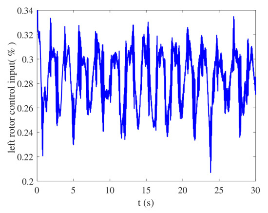
Figure 11.
The left main rotor control input of the VTOL-UAV.
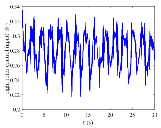
Figure 12.
The right main rotor control input of the VTOL-UAV.
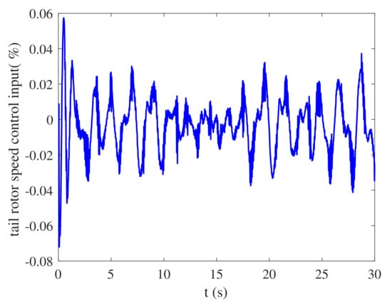
Figure 13.
The tail rotor speed control input of the VTOL-UAV.
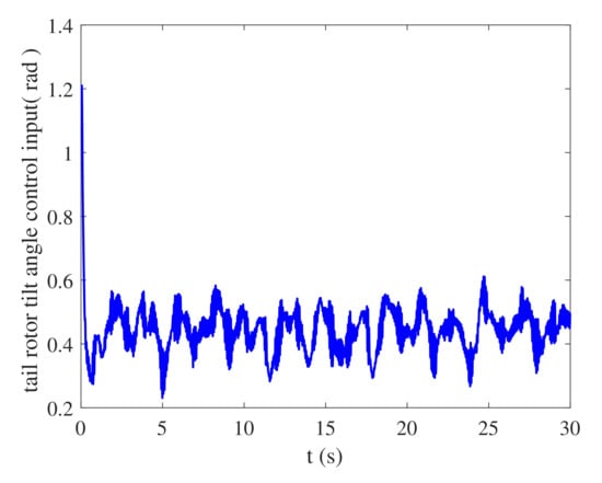
Figure 14.
The tail rotor tilt angle control input of the VTOL-UAV.
4.2. Flight Test
The flight test of 8-word route tracking is carried out. The conditions are set as follows: the initial height is 57 m, the desired height is 130 m, and the desired horizontal velocity is 20 m/s. The test results are shown in Figure 15, Figure 16, Figure 17 and Figure 18.
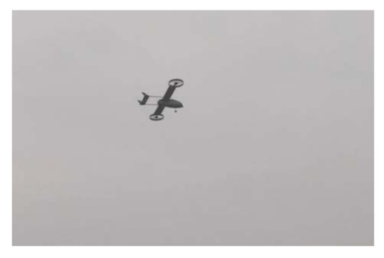
Figure 15.
The flight test.
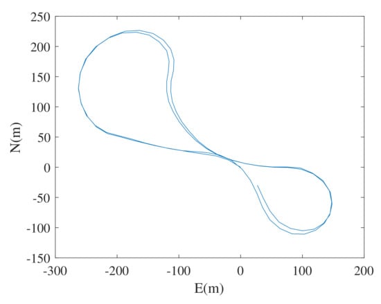
Figure 16.
The flight trajectory.
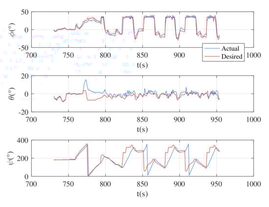
Figure 17.
The attitude angle response of the tri-rotor ducted VTOL-UAV.
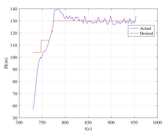
Figure 18.
The height response of the tri-rotor ducted VTOL-UAV.
From the flight test results, the VTOL-UAV can complete the 8-word route flight with high consistency. Specifically, the roll control has high precision and fast response. There is obvious time delay in pitch angle and heading angle control. The altitude control accuracy is within ±4 m, which is due to the large aircraft mass, slow system response and large control force. The longitudinal control and heading control are mainly realized through the tail rotor, with small rotor disc area and small control force. At the same time, the pitch channel is coupled with the heading channel, resulting in height and heading oscillation. This phenomenon can be improved by optimizing the control strategy in the transition process and limiting the change rate of pitch angle command.
5. Conclusions
In this paper, a compound control method combining model prediction control improved with disturbance observer and sliding mode nonlinear dynamic inversion is proposed for the three culvert rotor composite VTOL-UAV with tiltable tail rotor. The robust trajectory tracking control with the composite disturbance is realized. First, the nonlinear dynamic inverse is improved with the sliding mode for the inner loop, and the controller is designed. For the outer loop, the E-SSPC method is used to deduce the prediction model, and the model predictive controller is designed by using nominal error dynamic system. The sliding mode disturbance observer based on super-twisting algorithm is introduced into the position controller to estimate and compensate the composite disturbance, which enhances the robustness of the model predictive controller. The effectiveness and robustness of the compound control scheme are verified by numerical simulation experiments. Finally, the flight test is carried out.
Author Contributions
Conceptualization, Y.H., J.G. and P.Y.; methodology, Y.H. and J.G.; software, J.G.; data curation, P.Y. and G.Z.; writing—original draft preparation, Y.H.; writing—review and editing, Y.H.; supervision, N.C. All authors have read and agreed to the published version of the manuscript.
Funding
This research was supported in part by the Beijing Natural Science Foundation (4222050) and in part by the National Natural Science Foundation of China (62173030).
Data Availability Statement
The data presented in this study are available on request from the corresponding author.
Acknowledgments
The authors gratefully acknowledge the reviewers for their careful work and thoughtful suggestions that have helped improve this paper.
Conflicts of Interest
The authors declare no conflict of interest.
References
- Future Long Range Assault Aircraft. Available online: https://www.boeing.com/defense/future-long-range-assault-aircraft/index.page{#}/videos/defiant-x-exceeds-230-knots (accessed on 21 March 2022).
- Helicopters History. Available online: https://www.airbus.com/en/who-we-are/our-history/helicopters-history/x3 (accessed on 21 March 2022).
- Yang, K.; Han, D.; Shi, Q. Study on the lift and propulsive force shares to improve the flight performance of a compound helicopter. Chin. J. Aeronaut. 2021, 35, 365–375. [Google Scholar] [CrossRef]
- Yan, K.; Chen, M.; Wu, Q.; Zhu, R. Robust adaptive compensation control for unmanned autonomous helicopter with input saturation and actuator faults. Chin. J. Aeronaut. 2019, 32, 2299–2310. [Google Scholar] [CrossRef]
- Xian, B.; Guo, J.; Zhang, Y.; Zhao, B. Sliding mode tracking control for miniature unmanned helicopters. Chin. J. Aeronaut. 2015, 28, 277–284. [Google Scholar] [CrossRef] [Green Version]
- Wang, C.; Wang, X. Design of a controller for hypersonic vehicle based on sliding mode disturbance observer. Electron. Opt. Control. 2020, 27, 90–94. [Google Scholar]
- Tan, S.; Guo, J.; Zhao, Y.; Zhang, J. Adaptive control with saturation-constrainted observations for drag-free satellites—A set-valued identification approach. Sci. China Inf. Sci. 2021, 64, 182–193. [Google Scholar] [CrossRef]
- Li, Y.; Liu, X.; He, Q. An adaptive dynamic inversion control method based on improved piecewise constant for flight control system. J. Northwestern Polytech. Univ. 2021, 39, 167–174. [Google Scholar] [CrossRef]
- Lu, B. Research on High-Bandwidth/High-Precision Longitudinal Control for a Hypersonic Vehicle; Nanjing University of Aeronautics and Astronautics: Nanjing, China, 2008. [Google Scholar]
- Zhou, H. Small-Scale Unmanned Helicopter Modeling and Controller Design; South China University of Technology: Guangzhou, China, 2011. [Google Scholar]
- Wang, X.; Meng, X.; Li, C. Design of trajectory tracking controller for UAV based on MPC. Syst. Eng. Electron. 2021, 43, 191–198. [Google Scholar]
- Chen, J.; Sun, R.; Zhu, B. Disturbance observer-based control for small nonlinear UAV systems with transient performance constraint. Aerosp. Sci. Technol. 2020, 105, 106028. [Google Scholar] [CrossRef]
- Li, Y.; Chen, M.; Ge, S.S.; Li, D. Anti-disturbance control for attitude and altitude systems of the helicopter under random disturbances. Aerosp. Sci. Technol. 2019, 96, 105561. [Google Scholar] [CrossRef]
- Wang, Q. A Numerical Analysis of the Aerodynamic Performance of the Ducted-Fan UAV; National University of Defense Technology: Changsha, China, 2008. [Google Scholar]
- Wang, S. Theory and Simulation on Overall Design and Control System of the Saucer Ducted Unmanned Aerial Vehicle; Fudan University: Shanghai, China, 2011. [Google Scholar]
- Kong, W. Research on some Key Technical Issues of Composed High Speed Helicopter; Nanjing University of Aeronautics and Astronautics: Nanjing, China, 2011. [Google Scholar]
- Hu, Y. Research on System-Identification-Based Dynamic Modelling and Control Technology for High-Speed Helicopter; Beihang University: Beijing, China, 2020. [Google Scholar]
- Shen, H. Research in the Interaction Flow Field of Compound High-Speed Helicopter Rotor/Fuselage/Auxiliary Propulsor; Nanjing University of Aeronautics and Astronautics: Nanjing, China, 2015. [Google Scholar]
- Wang, Q.; Chen, M.; Xu, G. Control strategy for compound coaxial helicopter under conversion mode. J. Aerosp. Power 2014, 29, 458–466. [Google Scholar]
- Chen, N. Research on Nonlinear Robust Control Technology for Unmanned Helicopter; Beihang University: Beijing, China, 2018. [Google Scholar]
- Bai, Y.; Shi, X.; Wang, S. Auv attitude control system design with robust nonlinear dynamic inversion. Tactical Missile Technol. 2016, 2, 93–97. [Google Scholar]
- Dávila, A.; Moreno, J.A.; Fridman, L. Variable gains super-twisting algorithm: A lyapunov based design. In Proceedings of the 2010 American Control Conference, Baltimore, MD, USA, 30 June–2 July 2010; IEEE: Piscataway, NJ, USA, 2010; pp. 968–973. [Google Scholar]
- Evangelista, C.; Puleston, P.; Valenciaga, F. Lyapunov-designed super-twisting sliding mode control for wind energy conversion optimization. IEEE Trans. Ind. Electron. 2013, 60, 538–545. [Google Scholar] [CrossRef]
- Moreno, J.A.; Osorio, M. Strict lyapunov functions for the super-twisting algorithm. IEEE Trans. Autom. Control. 2012, 57, 1035–1040. [Google Scholar] [CrossRef]
- Tan, J.; Zhou, Z.; Zhu, X.; Xu, X. Fast super twisting algorithm and its application to attitude control of flying wing UAV. Control. Decis. 2016, 31, 143–148. [Google Scholar]
- Yang, F.; Tan, S.; Xue, W.; Guo, J.; Zhao, Y. Extended state filtering with saturation-constrainted observations and active disturbance rejection control of position and attitude for drag-free satellites. Acta Autom. Sin. 2020, 46, 2337–2349. [Google Scholar]
Publisher’s Note: MDPI stays neutral with regard to jurisdictional claims in published maps and institutional affiliations. |
© 2022 by the authors. Licensee MDPI, Basel, Switzerland. This article is an open access article distributed under the terms and conditions of the Creative Commons Attribution (CC BY) license (https://creativecommons.org/licenses/by/4.0/).