Abstract
As technology continues to leap forward and innovations advance, the systems of civil aircraft are becoming increasingly sophisticated and complex. Accordingly, there is a rising amount of information to be processed by pilots in the cockpit, increasing their cognitive burden, which significantly threatens the safety of flight. Thus, designers have formulated cockpit layout principles relating to importance, frequency of use, functional grouping, and operation sequence on the basis of ergonomics, which can effectively reduce the cognitive burden for pilots. The degree to which the cockpit layout of a model conforms to the four design principles can indicate its ergonomic design level. In accordance with the concepts of the above four cockpit layout principles, evaluation methods for determining their respective conformity to the four design principles were proposed in this paper. These methods use the operational sequence of cockpit system controls used in the normal flight mission of the actual aircraft type as the evaluation data source. Subsequently, the total evaluation results for cockpit layout were obtained using the weighted accumulation method. Lastly, the process for evaluating the cockpit layouts of civil aircraft was illustrated using the cockpits of the A320 series and B737NG series as examples. Based on the final evaluation results, the feasibility and effectiveness of the proposed evaluation method was verified.
1. Introduction
The first aircraft was developed a century ago. Since then, several innovations aircraft cockpit have been made. In the period leading up to and following World War I, the initial absence of cockpit instruments, which meant that successful manipulation of the aircraft relied on the pilot’s experience and instincts, gave way to the development of simple instruments providing access to critical information to guide flight. Currently, as information technology, communication and navigation, integrated-circuit and other novel technologies are extensively used, the development of aircraft cockpits is shifting to automation and intellectualization, which significantly improves the pilot’s working environment and aircraft safety. Moreover, aircraft systems and components are becoming larger and more complicated to satisfy the growing new demand, thus bringing new challenges to aircraft safety.
Civil aircraft, an important type of aircraft, have developed rapidly over the past few years, being a convenient, comfortable and fast mode of travel. Although aviation safety is improving, flight accidents have not been completely eliminated, and hence the safety of civil aircraft has aroused increasing attention. Statistics suggests that around 70% of accidents are caused by improper operation or the misjudgment of pilots [1,2]. Due to the increase in the complexity of aircraft systems and operations, pilots are required to receive an increasing amount of information and provide feedback on the information. The resulting cognitive overload of pilots can easily lead to misjudgments and operations [3,4]. To address these negative effects, scholars have started to investigate the ergonomics of the cockpit in the interest of reducing pilots’ mental load.
The cockpit is the workplace where the crew can acquire information from each system and give feedback operations to ensure the flight is safe, comfortable and efficient [5]. Moreover, it is a vital system in the research and development process of civil aircraft. The design of the cockpit has a direct effect on pilot efficiency and flight safety [6]. For this reason, focusing ergonomic design to reduce the risks in human–machine interaction in the research and development of cockpit design in civil aircraft has become an urgent problem.
In general, the existing research areas in cockpit ergonomic design primarily fall into spatial layout optimization, display and operation control design, human–machine system modeling, pilot workload evaluation and human–machine interaction risk evaluation [7]. The major aim of this paper is to propose a method to evaluate the quality of the cockpit layout. This paper provides a reference for the design of cockpit layout optimization, which pertains to the study of layout optimization methods. In the following, the research status on cockpit layout optimization is described.
The design of layout optimization is a vital step in the overall product scheme design. Layout design can be divided into two categories: layout without performance constraints and layout with performance constraints. To be specific, layout without performance constraints aims to improve space utilization while requiring no interference between objects, while layout with performance constraints must take into account certain constraints (e.g., the effects of the aircraft layout on maneuverability, stability, electromagnetic field and other constraints) [8]. There have been extensive studies on layout design methods, most of which include layout design methods based on heuristic algorithms, graph theory-based methods and human–machine combination algorithms.
For heuristic algorithms, Beasley [9] proposed a dynamic programming-based heuristic algorithm capable of solving the unconstrained two-dimensional (2D) layout optimization problem. Niusong [10] used a genetic algorithm for civil aircraft cockpit layout optimization. In the study, he quantified the layout of the principles into component importance weights, and encoded layout elements with object-oriented real-coded method. On that basis, a mathematical model of cockpit layout based on matching degree was built, thus solving the optimization model with the genetic algorithm. Sadan Kulturel-Konak [11] first successfully applied particle swarm to address the layout optimization problem of irregular graphics in 2011. Since there is no mutation and crossover operation in genetic algorithm, particle swarm optimization is considered to be a more convenient option. Tsai et al. [12] used a heuristic algorithm based on the joint action of horizontal and vertical operators. Huang et al. [13] proposed a layout method using a simulated annealing algorithm for filling layout problems, which simulated the placement of objects under different “temperature” conditions, thus resulting in a significant increase in the computational efficiency.
To solve layout design in accordance with the graph theory, the objects to be laid out and their relative position relationships are generally first expressed by points and edges in the graph. Subsequently, an algorithm is adopted to determine the specific position relationships among the layout objects. Hashimshony [14] et al. built a model for generating possible alternative layout graphs in accordance with the graph theory under given programmatic requirements and constraints. Feng E [15] et al. took the layout of an artificial satellite return capsule design as an example. Based on the graph theory and the group theory, an algorithm of global optimization was presented, capable of solving layout problems in 2D. Yuan Miaolong [16] proposed a heuristic rule for sequential planning of layout solutions and the heuristics-based layout solution, which has been primarily used for solving 3D-constrained layout design.
The combined human–computer algorithm is a method integrating the abstract thinking of a human with the computational power of a computer. Weiqing He [17] et al. built a graph layout model based on constraints, in which the users can input positions for nodes and constraints over the node positions via an interface; subsequently, the computer gives a reasonable layout. Lenat, Feigenbaum [18] and Qian [19] generalized the theory of “human–machine integration” to deal with practical engineering problems.
In this paper, a method is proposed to evaluate the quality of cockpit layout following the layout design principles in accordance with the theory of human thinking set and order memory. Using statistical methods and mathematical models, the cross-linking relationship between the display and control components of each system and their importance in normal flight procedures are quantified, and a cockpit layout evaluation model is designed based on the results. The evaluation results could serve as an effective basis and data support to optimize the aircraft cockpit layout.
2. Civil Aircraft Cockpit Layout Design Principles and Related Theories
The civil aircraft cockpit is a space that integrates the control and display components of the respective complex systems in aircraft operation. The new generation aircraft incorporate numerous highly integrated display control technologies. For example, the A320 and B737 series aircraft include more than 500 control and display components. Without proper design and layout, pilots will face difficulties in quickly and accurately identifying information and making correct decisions in a given scenario. Accordingly, cockpit layout is designed in accordance with the “human-centered” design concept, and pilots’ abilities and limitations are fully considered. Pilots’ cognitive characteristics and cognitive processes are analyzed, and human–machine functions are appropriately allocated to ensure that pilots are able to acquire various information without exceeding their information-processing capacities [20,21]. After years of cockpit design and development, the following cockpit layout design principles have been generally accepted [10].
- (1)
- Principle of importance
Operation components are arranged according to their degree of importance, with the important ones placed in the optimal viewpoint position to ensure the quality of flight operations. Accordingly, the coordination of the information acquisition and information output of the control display devices are improved, while the basic functional requirements are met. In the above process, the importance of the components determines their layout positions. The more important components should be arranged within the optimal field of vision of the relevant person, or within the optimal operating range of human hands.
- (2)
- Use-frequency principle
The mental burden is reduced by placing the most frequently used display and control elements in locations where they can be easily sensed and operated by the pilots. The more commonly used meters and controllers are placed in sensitive locations and separated from other less commonly used instruments or controls, so the system components can be located quickly and accurately to avoid misuse. Comfortable and fast operation will reduce the physiological and psychological burden and reduce fatigue, thus increasing efficiency.
- (3)
- Functional grouping principle
The display and control components are classified according to function and use, and those with similar functions are placed together for easy identification and operation. For example, the controls for dealing with engine fires, such as the APU’s fire alarm button and the extinguishing agent button, are best arranged adjacent to each other, so that when encountering APU fire, the pilot can quickly find all the controls to address the fire. In the design of the system, the functional division should be arranged to increase work efficiency. Thus, in human–machine design, the first step is to distinguish the functional characteristics of the design object. This can facilitate the coordinated design and location of components with similar functions, thus increasing the efficiency and accuracy of operation and the safety of system operation.
- (4)
- operation sequence principle
To complete a certain operation easily and quickly, the relevant components must be observed and operated in a certain order. Consequently, the components should be arranged in the order of use. For example, after adjusting the Mach number with the speed knob, the pilot will observe the speed change on the real-time flight speed display. Therefore, the speed knob and the speed display are best arranged together to facilitate the pilot’s operation. The general operation order is sequential, going from left to right and from top to bottom, with the directional and positional arrangement of components facilitating the activity, which is of great significance to the operation as a whole. Cockpit components are sometimes operated in line with a fixed process, which enables the pilot to be mentally prepared and prevents any difficulty in finding the next object by providing a simple component layout. It is noteworthy that interrelated components can reduce incorrect operation in emergency situations.
In other words, the problem of evaluating the cockpit layout of an aircraft can be translated into the question of how well the layout of the aircraft conforms to the above four design principles. Accordingly, the cockpit layout evaluation method studied in this paper was based on the above four principles, and a basic evaluation model in the form of Equation (1) was built.
is the degree of compliance of the cockpit layout with the design principles. The calculation of each is the core of this paper, and is described in detail in the next section. denotes the weight coefficient of the ith design principle, determined by a decision analysis method commonly used in recent years—the analytic hierarchy process (AHP). AHP is a hierarchical weighting decision-analysis method proposed by Saaty in the early 1970s, and extensively used in various fields for its convenience and simplicity, good systematicity, and combination of qualitative and quantitative evaluation [22,23,24]. The application method is outlined in the following.
First, it was necessary to interview a certain number of relevant professionals, inviting them to compare the respective importance of two factors and accord them each a rating in the range of 1–10. A higher value accorded to one factor implied that it was more important than the other, and the evaluation score between all the elements constituted the evaluation judgment matrix A. Subsequently, the weight coefficient of each element was obtained according to the following steps.
For the given judgment matrix A, take any initial vector ^T, where , and .
The following equation was implemented for k-1st iterations to find the k-1st approximation of the first eigenvalue of A and the k-1st regularized approximation of the regularized eigenvector W corresponding to , such that A , which proves that ˜, where is the actual weight vector.
The accuracy requirement is given beforehand, and when , is yielded as the calculation result, otherwise turn to (2). However, the final calculation results are not necessarily certain to meet the actual situation, since human judgment may consider in this contradictory situation. Thus, the consistency test of the judgment matrix is required, and the test formula is written below.
where:
CI——Consistency index;
RI——Random consistency index;
CR——Consistency ratio;
CR denotes the consistency ratio, the smaller CR implies the better consistency of the evaluation and RI is the random consistency index, obtained from the Table 1. When the determined CR < 0.1, the judgment matrix is considered to meet the consistency requirement.

Table 1.
Summary table of RI values of n-order judgment matrix.
3. Evaluation Method for Cockpit Layout of Civil Aircraft
The civil aircraft cockpit layout evaluation method falls into four parts in accordance with four cockpit design principles. The first principle is the importance principle, requiring designers to place vital information and control components in the optimal display and control areas in the cockpit. The first part of the evaluation model is formulated based on the above principle.
Existing ergonomics researchers have proposed the concepts of optimal reachable domain and optimal visible domain. They have analyzed and determined the control positions of the human body for the optimal reachable and visible domains, on the basis of statistical static and dynamic posture data. In accordance with findings in studies such as [8], the best and general visible domain of a person is shown in Figure 1, and the best and general reachable domain of a person is shown in Figure 2.
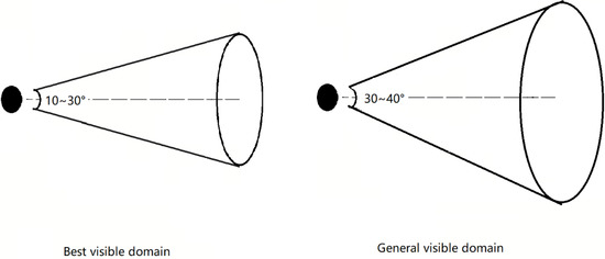
Figure 1.
Horizontal and vertical visible domains of the human body.
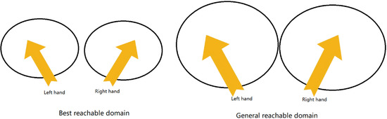
Figure 2.
The reachable domain of human sitting posture.
As depicted in the above figure, the optimal visible domain of human body is a cone space with an apex angle of 30° right in front of the eyes, and the optimal reachable domain of hands is a small area under the horizontal elbow posture of the arms. In the cockpit, the pilot sits in a normal position. His optimal visible domain is in front of the windshield and the monitor or instrument directly below windshield. The optimal reachable domain of his hands is in the front half of the central console. Accordingly, the importance layout principle was evaluated using statistics in terms of whether important information and controls were laid out in the optimal visible domain and reachable domain, which is expressed below:
where is the total number of important controls in the cockpit; is the number of important controls that are laid out in the optimal reachable domain of the pilot in this airplane; denotes the total amount of important information in the cockpit; is the amount of important information that are arranged in the optimal visible domain of the pilot in this airplane.
In general, the critical information and controls are the most influential aircraft flight safety information and controls, so important controls and information generally pertain to the aircraft control system and power system. Thus, the evaluation of the importance layout principle refers to counting the number of display controls of the control system and power system in the optimal visible domain and reachable domain.
The second part of the cockpit layout evaluation method was developed in terms of the principle of frequency of use, which requires that the frequently used display controls in the cockpit be placed in a position easily accessible to the pilot. As depicted in Figure 1 and Figure 2, the normal range of the human static visible domain is a cone space with an apex angle of 40° directly in front of the eyes, and the normal reachable domain range of hands is the space that the elbow can sweep. In the cockpit of a civil aircraft, the static visible domain from the normal sitting position of the pilot consists of the windshield, the display or instrument panel on both sides and below the windshield; the normal two-handed reachable domain should include the front part of the central control console, the instrument panel and the shutter. Accordingly, the use-frequency principle can be evaluated based on the statistics regarding whether the high-frequency display controls are laid out in the general visible domain and reachable domain, determined as written below:
where n is the number of subsystems frequently used in the normal flight process of the aircraft; is the number of controls of the subsystem i-th of the aircraft in the cockpit; denotes the number of controls of the i-th subsystem control in the cockpit that are laid out in the general visible or reachable domain.
In the model of this paper, to obtain high-frequency subsystem controls, the use number of the display control of each system in the cockpit during the entire process from normal takeoff to landing was firstly counted. Then, according to the amount of time from high to the final sort, the first 20% was taken for high-frequency display controls. Lastly, according to Equation (3), the compliance coefficient of frequency principle for cockpit layout was determined.
The third part of the cockpit layout evaluation method was designed to address the functional grouping principle. To be specific, controls with similar functions should be placed together to facilitate the associative memory of the pilot, so that only controls belonging to the same system can have similar functions in the aircraft. Thus, the functional grouping principle can be reflected by examining the layout concentrations of various systems in the cockpit controls of civil aircraft, as expressed below:
where n is the number of subsystems of all controls in the cockpit; is the control distribution concentration of i subsystem; is the total number of all controls of i subsystem; and is the maximum number of controls for i-th subsystem distributed on the same panel.
The fourth part of the cockpit layout evaluation method targeted the principle of sequence of operations. The principle of operation sequence requires that controls with a certain operation sequence in the normal operation process be placed next to each other, so that pilots can efficiently locate the next control to be operated after performing an operation. The above principle requires that the more interrelated the controls are in the operational flow, the closer they are to each other in the cockpit layout. Accordingly, a concept of task adjacency coefficient between system controls was first proposed in this paper, as expressed in Equation (5). The compliance of the cockpit layout with this principle was evaluated by comparing the mission adjacency coefficient between each control in the cockpit and the proximity of the control position in the actual layout.
where is the task proximity coefficient of the control components of system i and the control components of system j; denotes the frequency of the control components of system i being operated or viewed in a normal takeoff and landing process of the civil aircraft; and is the frequency of the control components of system i and the control components of system j controlled successively during the normal operation. The evaluation method for cockpit layout based on the operation sequence principle is written as:
where is the number of the higher task neighbor ratio among all controls of the subsystem of this aircraft type, with the threshold value of 0.5. denotes the number of adjacent layouts in the actual layout of the two subsystems with high task adjacency coefficient.
Besides the design of the evaluation calculation method for the four layout principles, the completion of the cockpit layout evaluation work should also be given a weight coefficient based on the importance of each principle. In this paper, pilots of different aircraft types were asked to rank the importance of four principles of cockpit layout according to their work experience. In this paper, analytic hierarchy process (AHP) was used to obtain the following judgment matrix through the statistics of ranking results. Weight judgment matrix of the four principles of cockpit layout is shown in Table 2.
Table 2.
Weight judgment matrix of the four principles of cockpit layout.
In accordance with the method in Section 2, the weight coefficients of four principles were determined, that is, , consistency ratio (significantly less than 0.1). The above coefficients indicate that the judgment matrix passed the consistency test and the determined results were valid. Thus, the final evaluation model of cockpit layout is:
The evaluation value of each principle in the formula can be substituted into the above calculation formula according to the actual cockpit layout, and the final evaluation result of a cockpit layout can be obtained by calculating the weights.
4. A Case Study of Cockpit Layout Evaluations for A320 and B737NG
To verify the effectiveness of the cockpit layout evaluation model proposed in this paper, the application of the evaluation method is presented in the following based on the evaluation of the cockpit layout of two typical passenger aircrafts of Boeing and Airbus. The evaluation results were compared and analyzed to verify the effectiveness of the proposed cockpit layout evaluation model.
The Boeing A320 series aircraft has been considered one of the best-selling series of civil aircraft. Its cockpit has been generally recognized by pilots for its intelligent, comfortable design and high level of commonality. Its cockpit layout is evaluated below. The A320 series aircraft consists of 38 subsystems based on the ATA chapter. The subsystems with display or control components distributed in the cockpit, as numbered by the ATA system, consist of 21. air conditioning, 22. automatic flight, 23. communication, 24. electrical, 25. equipment/decor, 26. fire alarm, 27. flight control, 28. fuel, 29. hydraulic, 30. anti-icing/rain, 31. indication system, 32. landing gear, 33. lights, 34. navigation, 35. oxygen, 36. air source, 49. APU and 70. power system. Each subsystem has multiple display or control components. To facilitate statistics and analysis, the following evaluations are based on the above 18 subsystems. Figure 3 illustrates the optimal and general visible domain and the optimal and general motion reachable domain of A320 series aircraft’s cockpit based on the area division of ergonomics. The red range is the optimal visible domain, the yellow range is the general visible domain, the orange range shows the optimal reachable domain, and the blue range is the general reachable domain.
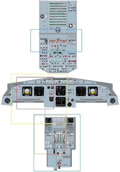
Figure 3.
Area division of the A320 cockpit.
For the A320, the critical subsystems affecting flight safety include the flight control system and the power system. Its flight control system involves 11 control components with different functions in the cockpit, with seven control components located in the center console and the side console, three located in the top panel, and one located in the visor. The vital display information of the flight control system is all located on the EFIS and ECAM interfaces. The powertrain has six control components, with five located on the center console and one located on the top panel. The key display information of the power system is located in the ECAM interface. In accordance with the division of the optimal visible domain and the optimal reachable domain, the evaluation score for the importance principle is written as:
In accordance with the FCOM manual of A320, we listed the actions that should be operated or checked in sequence, from flight preparation to crew disembarkation, in A320 series aircraft. Subsequently, the frequency of operation or checking of each subsystem control was calculated, and the results are listed in Table 3.
Table 3.
Operation frequency of control components for each subsystem of the A320 series during flight.
As depicted in the above table, the subsystems with operation frequency in the top 20% included 22. automatic flight, 27. flight control, 31. indication system and 34. navigation system. As suggested by the statistics, there were 19 control components in the automatic flight subsystem, all of which were distributed in the general reachable domain. The key information displayed on the ECAM, EFIS and MCDU interfaces were all in the general visible domain. There were 11 control components in the flight control subsystem, and 10 were in the general reachable domain. Its key display information was distributed in ECAM, EFIS, pertaining to the general visible domain. The indicating system consisted of 14 control components, distributed on the visor and the central instrument panel and within to the general reachable domain. Furthermore, its information was displayed on the ECAM and EFIS interfaces and the central instrument panel, all within the general visible domain. The navigation subsystem covered 24 control components, 19 of which were in the general reachable domain, and the key display information on the EFIS and the central instrument panel was within the general visible domain. Accordingly, the evaluation score for use of the frequency principle is written as:
A320 has 18 subsystems with controls distributed in the cockpit. According to Equation (6), the distribution concentration of the control components of each subsystem was statistically determined, and the results are listed in Table 4.
Table 4.
Distribution concentration of controls of each subsystem of A320.
According to Equation (6), the evaluation score for the functional grouping principle is expressed as:
As indicated by the FCOM manual of A320, the aircraft has nearly 350 operations from the cockpit preparation stage to crew disembarkation. In general, while it does not stipulate a required order for the checking of system controls at the stage of cockpit preparation, the airline company recommends that pilots should complete the flight tasks in strict compliance with the operation sequence of the manual at all stages. Table 5 lists the task-correlation coefficient between each system control determined by Equation (8) based on the control sequence composed of the task flow from taxiing to stopping operation in the FCOM manual.
Table 5.
Task-correlation coefficients among a range of system controls of A320.
As depicted in the above table, there were 14 pairs of subsystem controls with a task-correlation coefficient higher than or equal to 0.5, which revealed that the controls of the above systems followed a certain order of operations. As indicated by the actual layout of each system control in the A320 cockpit, 9 pairs of subsystem controls with high task-correlation coefficients were arranged adjacent to each other in the cockpit. Thus, the evaluation score for the operation process principle is expressed as:
Lastly, according to Equation (9), the weighted summation of the evaluation scores of the four layout principles was obtained to calculate the final A320 cockpit layout evaluation result:
Another evaluation case was Boeing’s 737 series, i.e., the largest competitor of the A320 series; the two occupy over half of the global mainline passenger aircraft market. The following is an evaluation of the conformity of the cockpit layout of the B737NG series aircraft with the four design principles.
Based on the area division of ergonomics, Figure 4 illustrates the optimal and general visible domain and the optimal and general motion reachable domain of B737NG series aircraft’s the cockpit. The red range is the optimal visible domain, the yellow range is the general visible domain, the orange range is the optimal reachable domain and the blue range is the general reachable domain.
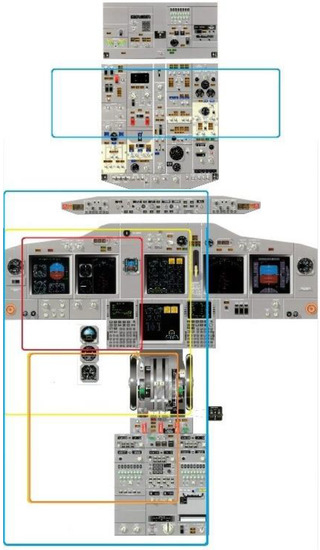
Figure 4.
Area division of the B737NG cockpit.
The critical subsystems of B737NG are also the flight control system and power system. Its flight control system has 19 controls with different functions, 13 controls on the central console and 6 controls on the front and rear top panels, along with 10 information displays on the top panel and 19 information displays on the console. The power system has 10 controls, including 8 controls on the center console and 2 controls on the front top panel, and vital information is displayed on the upper and lower display assemblies. Based on the division of the optimal view field and the optimal reachable field, the evaluation score for the importance principle is:
In accordance with the FCOM manual of B737NG, we devised a list of actions that should be operated or checked in sequence from flight preparation to crew disembarkation of B737NG series aircraft. Subsequently, the operation or checking frequency of each subsystem control was counted, and the results are listed in Table 6.
Table 6.
Operation frequency of control components of subsystem of B737NG series during flight.
As depicted in the above table, the subsystems with operation frequency in the top 20% included 22. automatic flight, 27. flight control, 31. indication system and 34. power system. The automatic flight system consisted of 24 controls on the visor, 3 controls on the center console, 15 displays on the PFD and center instrument panel and 6 displays on the visor. There were 13 controls for the flight control subsystem located on the central console, 6 controls located on the front and rear top panels, 10 displays located on the top panel and 19 displays on the central console. The 23 controls of the indicating system were on the instrument panel, two controls were located on the top panel, and the indication information was located on the instrument panel. The power system covered 10 operating controls, of which eight were located on the center console and two were on the front top panel. Moreover, the key information was displayed on the instrument panel. Accordingly, the evaluation score for use of the frequency principle is expressed as:
According to Equation (6), the control distribution concentration of each subsystem of B737NG was statistically determined, and the results are listed in Table 7.
Table 7.
Distribution concentration of the controls of each subsystem of B737NG.
According to Equation (6), the evaluation score for the functional grouping principle is determined as:
Based on the FCOM manual of B737NG, the control sequence consisting of the task flow from taxiing to stopping operation was counted, and the task-correlation coefficient between each system control was determined by Equation (8). The results are listed in Table 8.
Table 8.
Task-correlation coefficients among different system controls of B737NG.
As depicted in the above table, there were 13 pairs of subsystem controls with a task-correlation coefficient higher than or equal to 0.5, thus implying that the controls of the above systems followed a certain order of operation. As indicated by the actual layout of each system control in the B737NG cockpit, eight pairs of subsystem controls with high task-correlation coefficients were arranged adjacent to each other in the cockpit. On that basis, the evaluation score for the operation process principle is written as:
Lastly, according to Equation (9), the weighted summation of the evaluation scores of the four layout principles was obtained to calculate the final B737NG cockpit layout evaluation result:
As depicted in Figure 5, the cockpits of the A320 and B737NG series scored higher on the design principles of importance and frequency of use than on the principles of functional grouping and sequence of operations, which reveals that manufacturers pay more attention to the former. The cockpit of the A320 series achieves a score of higher than 0.85 in the design principles of importance and frequency of use, significantly better than that of the B737NG series. The cockpit of the B737NG series outperforms the A320 series in the design of functional groupings. This shows that the cockpits of the two civil aircraft have different emphases in the ergonomic design concept. As revealed by the results, the layout of the cockpit of the A320 and B737NG has been designed with the above four design principles in mind, but different emphases result in differences in the scores of each design principle. However, from the overall evaluation results, the layout of the A320 series cockpit outperforms that of the B737NG series, and the ergonomic design is considered to be more comprehensive.
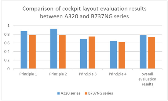
Figure 5.
Comparison of cockpit layout evaluation results between A320 and B737NG series.
5. Conclusions
This paper follows the four design principles of importance, frequency of use, function grouping and operation sequence in relation to the cockpit layout design of the civil aircraft. The operational sequence of the system controls of the cockpit was the evaluation data source, and the compliance of the cockpit of the aircraft type to the four design principles was determined. Lastly, the total evaluation value of the cockpit layout was obtained after weighted accumulation by the AHP method. In the above work, we obtained the following conclusions:
- (1)
- The four design principles of civil aircraft cockpit layout are capable of effectively reducing the mental burden of pilots, which is of great significance to flight safety.
- (2)
- The cockpit layout evaluation model built in this paper can quantify the conformity of the cockpit layout of an aircraft to the four design principles, and the evaluation results can provide a valuable reference for designers and decision makers with regard to aircraft cockpit layout.
- (3)
- The quantitative method of evaluating the cockpit layout of civil aircraft in this paper can provide objective data for cockpit layout evaluation, which can provide new constraint conditions and optimization ideas for layout optimization.
- (4)
- The limitation of the method in this paper is that it only covers the evaluation of four main layout principles. In fact, the cockpit layout of the aircraft must also involve other principles, such as operating comfort and anti-interference. In the future, these design principles can be evaluated by combining human data and aircraft cockpit data to expand the coverage of the evaluation model and make the evaluation results more comprehensive.
Author Contributions
Conceptualization, K.C. and Y.Z. (Yongjie Zhang); methodology, K.C., Y.Z. (Yongjie Zhang), Y.J. and Y.Z. (Yongqi Zeng); software, K.C. and Y.Z. (Yongqi Zeng); validation, K.C. and Y.J.; formal analysis, Y.Z. (Yongqi Zeng) and B.C.; investigation, Y.Z. (Yongqi Zeng) and B.C.; resources, Y.Z. (Yongqi Zeng), B.C. and W.D.; data curation, Y.J., B.C. and W.D.; writing—original draft preparation, K.C., Y.Z. (Yongjie Zhang) and B.C.; writing—review and editing, K.C., Y.Z. (Yongjie Zhang) and B.C.; visualization, K.C. and B.C.; supervision, Y.Z. (Yongjie Zhang); project administration, Y.Z. (Yongjie Zhang); funding acquisition, Y.Z. (Yongjie Zhang). All authors have read and agreed to the published version of the manuscript.
Funding
This research was funded by the National Natural Science Foundation of China (Grant Nos. 11972301, 11201375, 11972300), the Fundamental Research Funds for the Central Universities of China (Grant No. G2019KY05203), the Natural Science Foundation of Shaanxi Province (Grant No. 2018JQ1071), State Key Laboratory of Structural Analysis for Industrial Equipment (China) (Grant No. GZ18107).
Informed Consent Statement
Not applicable.
Data Availability Statement
Not applicable.
Conflicts of Interest
The authors declare no conflict of interest.
References
- Boeing Corporation. Statistical Summary of Commercial Jet Airplane Accidents Worldwide Operations 1959–2011; Boeing Corporation: Washington, DC, USA, 2012. [Google Scholar]
- Liu, X.; Li, F. Flight Accidents of Large and Medium Transport Aircraft; Aviation Industry Press: Beijing, China, 2012. [Google Scholar]
- Xu, Y.J. Safety issues arising from the development of cockpit technology. J. Civ. Aviat. Flight Acad. China 1998, 4, 28. [Google Scholar]
- Carvalho, P.; Santos, I.; Gomes, J.; Borges, M.; Guerlain, S. Human factors approach for evaluation and redesign of human-system interface of a nuclear power plant simulation. Sci. Direct. 2008, 29, 273–284. [Google Scholar]
- Stollings, M.N.; Amell, J.R. Crew centered cockpit design methodology. In Proceedings of the Aerospace Design Conference, Irvine, CA, USA, 3–6 February 1992. [Google Scholar]
- Verhoeven, R.; Reus, A.D. Human factors assistance during prototyping of cockpit applications. In Proceedings of the AIAA Modeling and Simulation Technologies Conference and Exhibit, Keystone, CO, USA, 21–24 August 2006. [Google Scholar]
- Zhang, Y. Research on Several Key Technologies of Ergonomic Design of Civil Aircraft Cockpit. Master’s Thesis, Nanjing University of Aeronautics and Astronautics, Nanjing, China, 2014. [Google Scholar]
- Li, G. Several Theories, Methods and Applications of Layout Scheme Design. Master’s Thesis, Dalian University of Technology, Dalian, China, 2003. Available online: https://d.wanfangdata.com.cn/thesis/Y638227 (accessed on 3 May 2022).
- Beasley, J.E. Algorithms for unconstrained two-dimensional guillotine cutting. J. Oper. Res. Soc. 1985, 36, 297–306. [Google Scholar] [CrossRef]
- Song, N. Layout Optimization Research for Ergonomic Design of Civil Aircraft Cockpit. Master’s Thesis, Nanjing University of Aeronautics and Astronautics, Nanjing, China, 2013. [Google Scholar]
- Kulturel-Konak, S.; Konak, A. A new relaxed flexible bay structure representation and particle swarm optimization for the unequal area facility layout problem. Eng. Optim. 2011, 43, 1263–1287. [Google Scholar] [CrossRef]
- Tsai, C.C.; Chen, S.J.; Feng, W.S. An HV alternating router. IEEE Trans. Comput.-Aided Des. Integr. Circuits Syst. 1992, 11, 976–991. [Google Scholar] [CrossRef]
- Huang, W.Q.; Kang, Y. A heuristic quasi-physical strategy for solving disks packing problem. Simul. Model. Pract. Theory 2002, 10, 195–207. [Google Scholar]
- Hashimshony, R.; Roth, J. ALG: A model for generating alternative layout graphs under architectural constraints. Comput.-Aided Des. 1986, 18, 431–436. [Google Scholar] [CrossRef]
- Feng, E.; Wang, X.; Wang, X.; Teng, H. An algorithm of global optimization for solving layout problems. Eur. J. Oper. Res. 1999, 114, 430–436. [Google Scholar] [CrossRef]
- Yuan, M.L.; Zhou, J. A class of heuristic solution algorithms for 3D geometric layout. Chin. J. Comput. 1999, 22, 923–930. [Google Scholar]
- He, W.; Marriott, K. Constrained graph layout. In International Symposium on Graph Drawing; Springer: Berlin/Heidelberg, Germany, 1997; pp. 217–232. [Google Scholar]
- Lenat, D.B.; Feigenbaum, E.A. On the thresholds of knowledge. Artif. Intell. 1991, 47, 185–250. [Google Scholar] [CrossRef]
- Qian, X.; Yu, J.; Dai, R. A new field of science—Open complex giant systems and its methodology. Nat. Mag. 1990, 13, 3–10. [Google Scholar]
- Szczepanski, C. Method of optimizing the human-machine interface at military aircraft. In Proceedings of the AIAA Modeling and Simulation Technologies Conference, Chicago, IL, USA, 10–13 August 2009. [Google Scholar]
- Liu, X.; Yu, S.; Chu, J.; Yao, L.; Zhang, W.; Zhao, M. Airplane cockpit ergonomic layout optimization based on improved PSO algorithm combining grouping and ranking. Comput. Eng. Appl. 2015, 51, 1–6. [Google Scholar]
- Vaidya, O.S.; Kumar, S. Analytic hierarchy process: An overview of applications. Eur. J. Oper. Res. 2006, 169, 1–29. [Google Scholar] [CrossRef]
- Sato, Y. Comparison between multiple-choice and analytic hierarchy process: Measuring human perception. Int. Trans. Oper. Res. 2010, 11, 77–86. [Google Scholar] [CrossRef][Green Version]
- Lavagna, M. Preliminary spacecraft design: Genetic algorithms and AHP to support the concurrent process approach. In Proceedings of the International Astronautical Congress of the International Astronautical Federation, Bremen, Germany, 29 September–3 October 2003. [Google Scholar]
Publisher’s Note: MDPI stays neutral with regard to jurisdictional claims in published maps and institutional affiliations. |
© 2022 by the authors. Licensee MDPI, Basel, Switzerland. This article is an open access article distributed under the terms and conditions of the Creative Commons Attribution (CC BY) license (https://creativecommons.org/licenses/by/4.0/).