

Lift Augmentation at Subsonic Speeds by Lateral Jets for a Hypersonic Aircraft

 ,
,  ,
,
Abstract
1. Introduction
2. Numerical Methods
2.1. Governing Equations
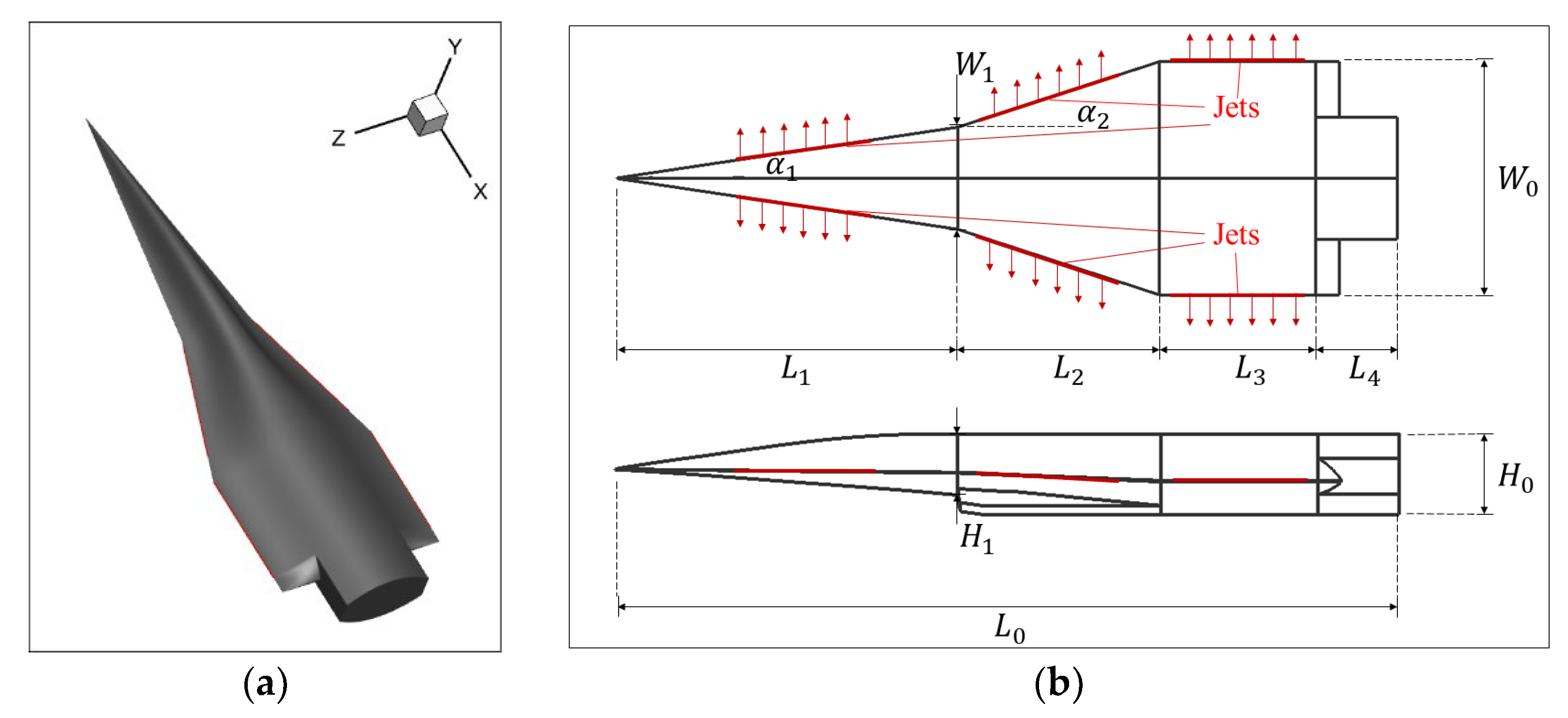
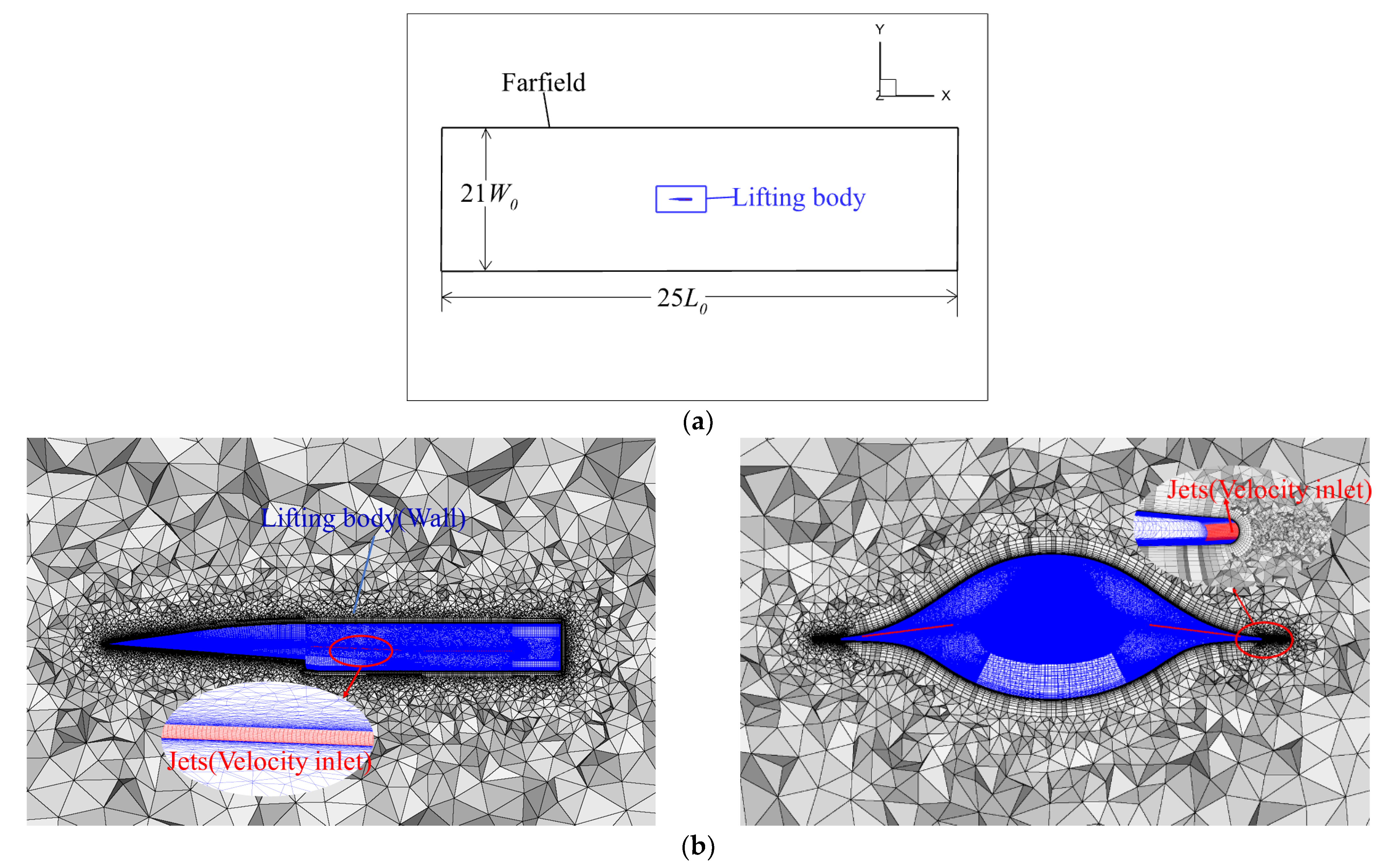
2.2. Baseline Geometry and Computational Grid
3. Validations
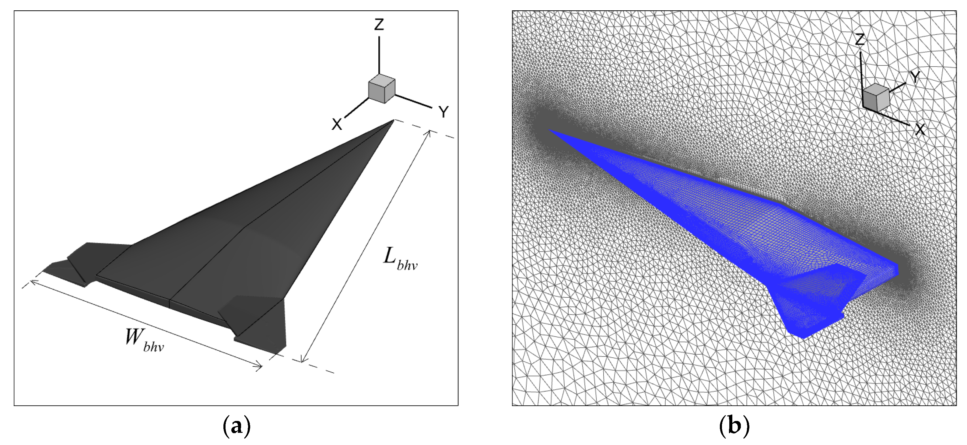
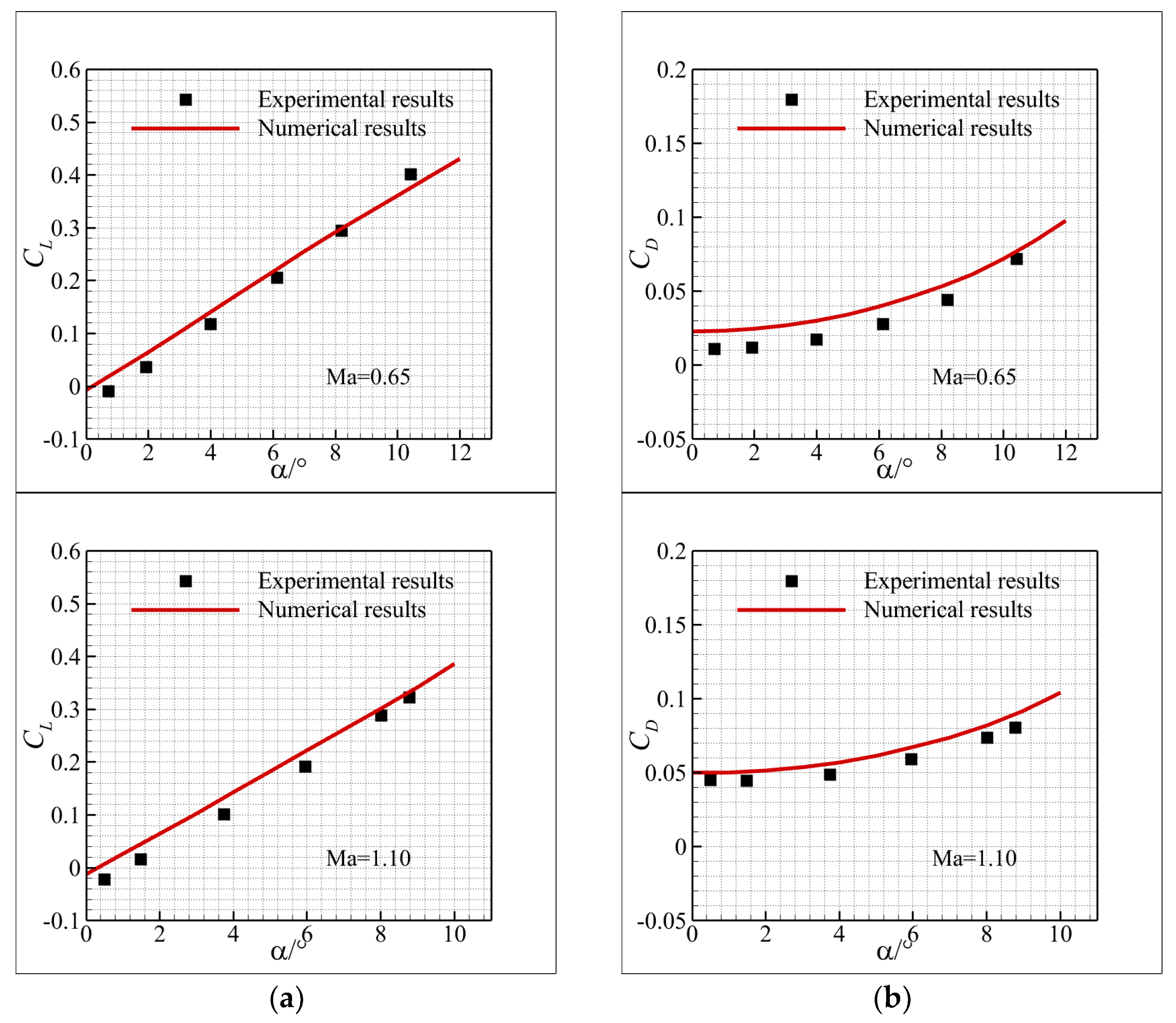
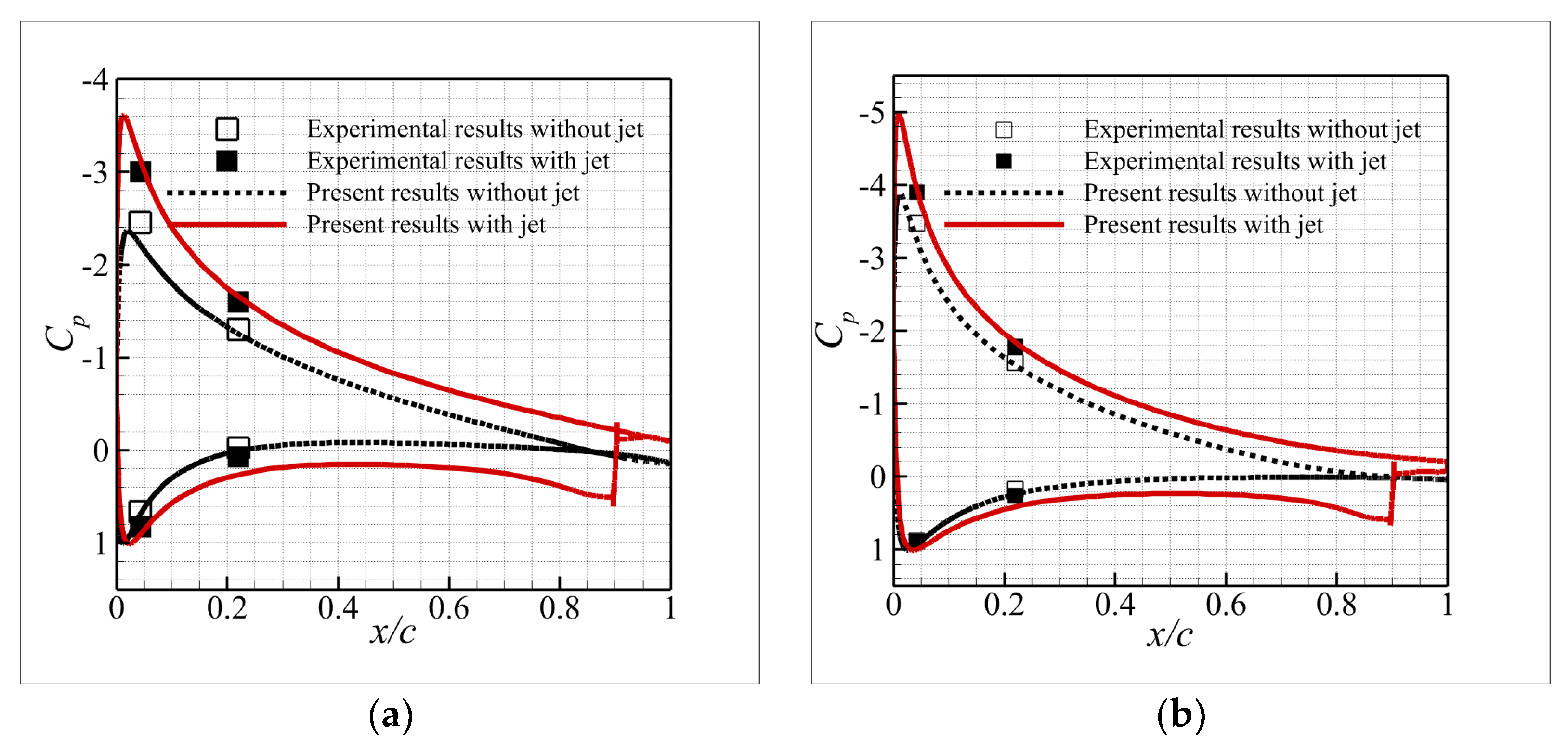
3.1. The BHV Model
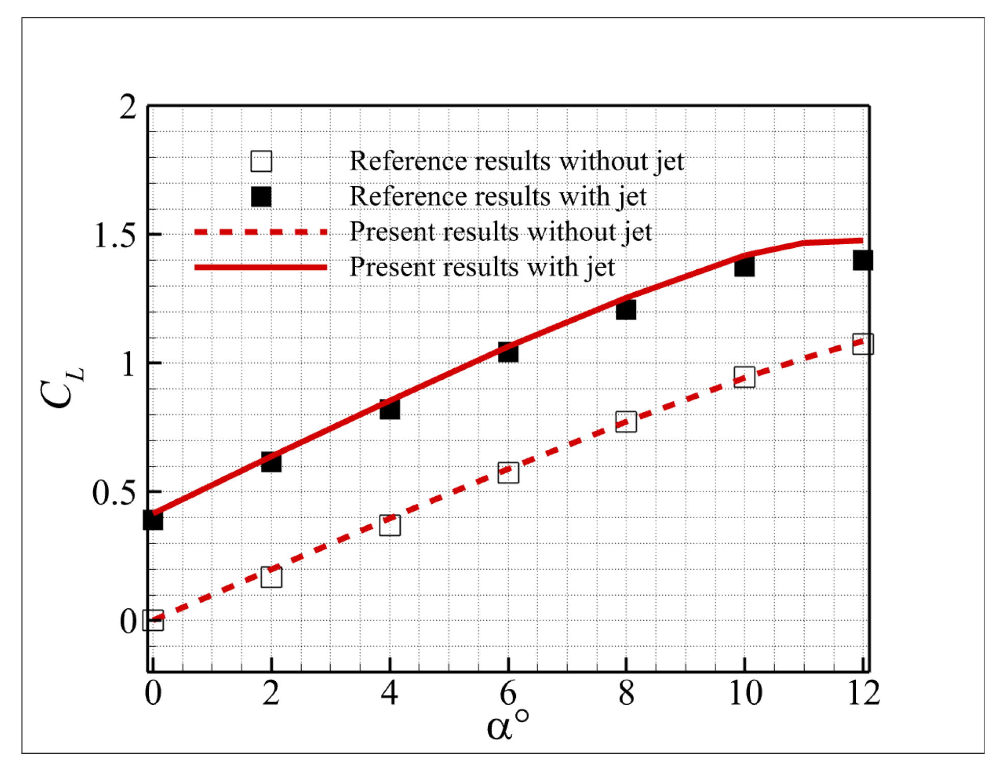
3.2. The Jet Modelling
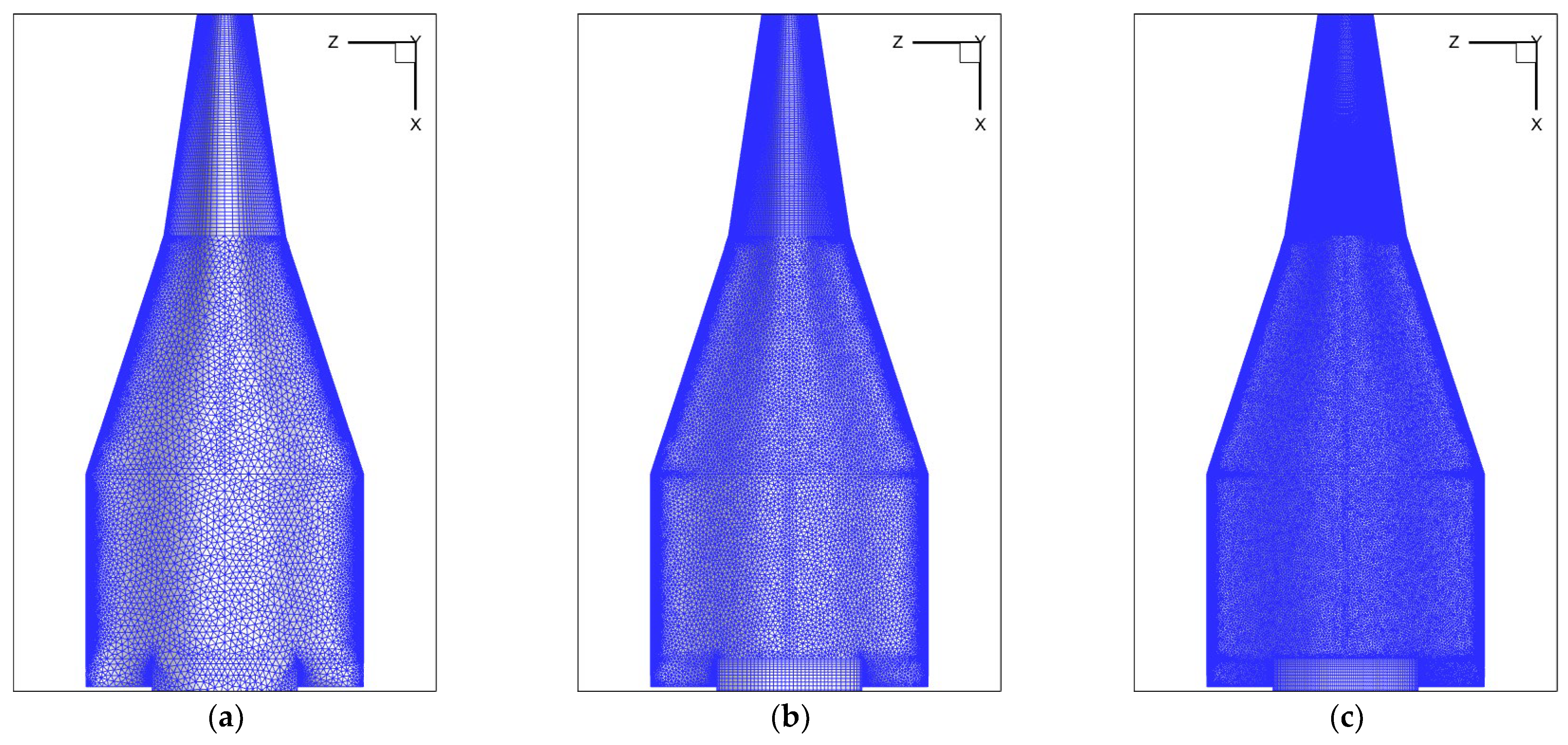
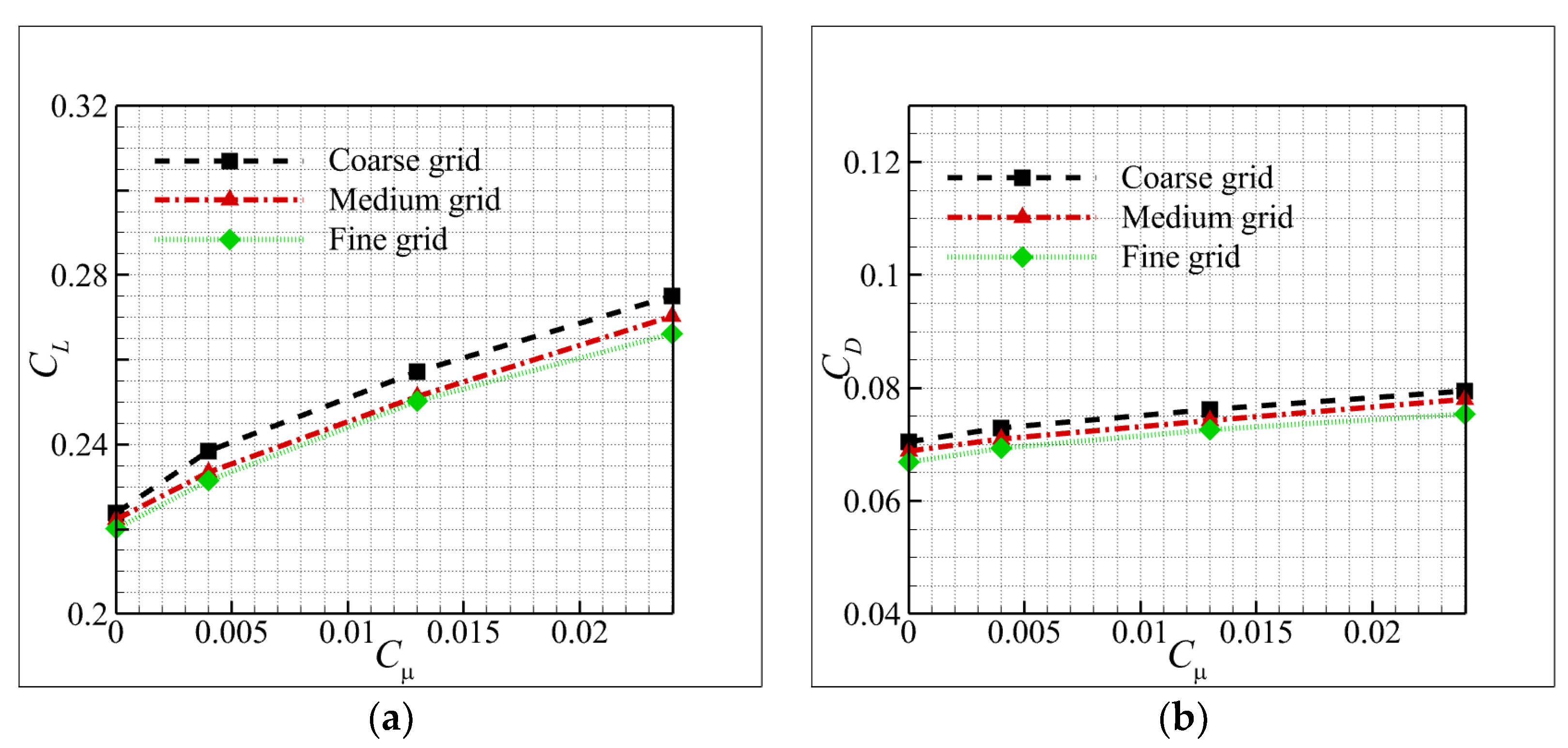
3.3. Grid Convergence Study
4. Results and Discussion
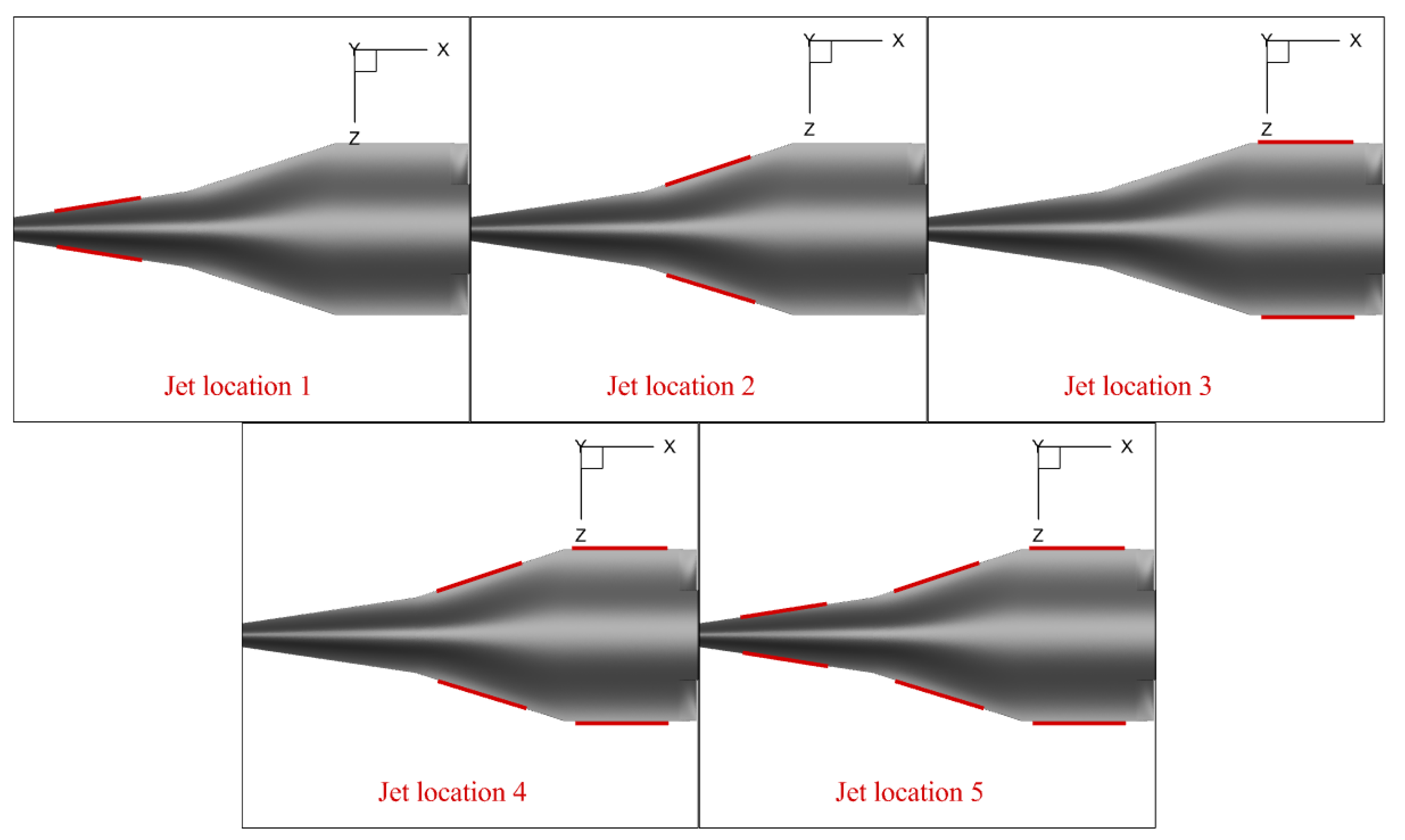
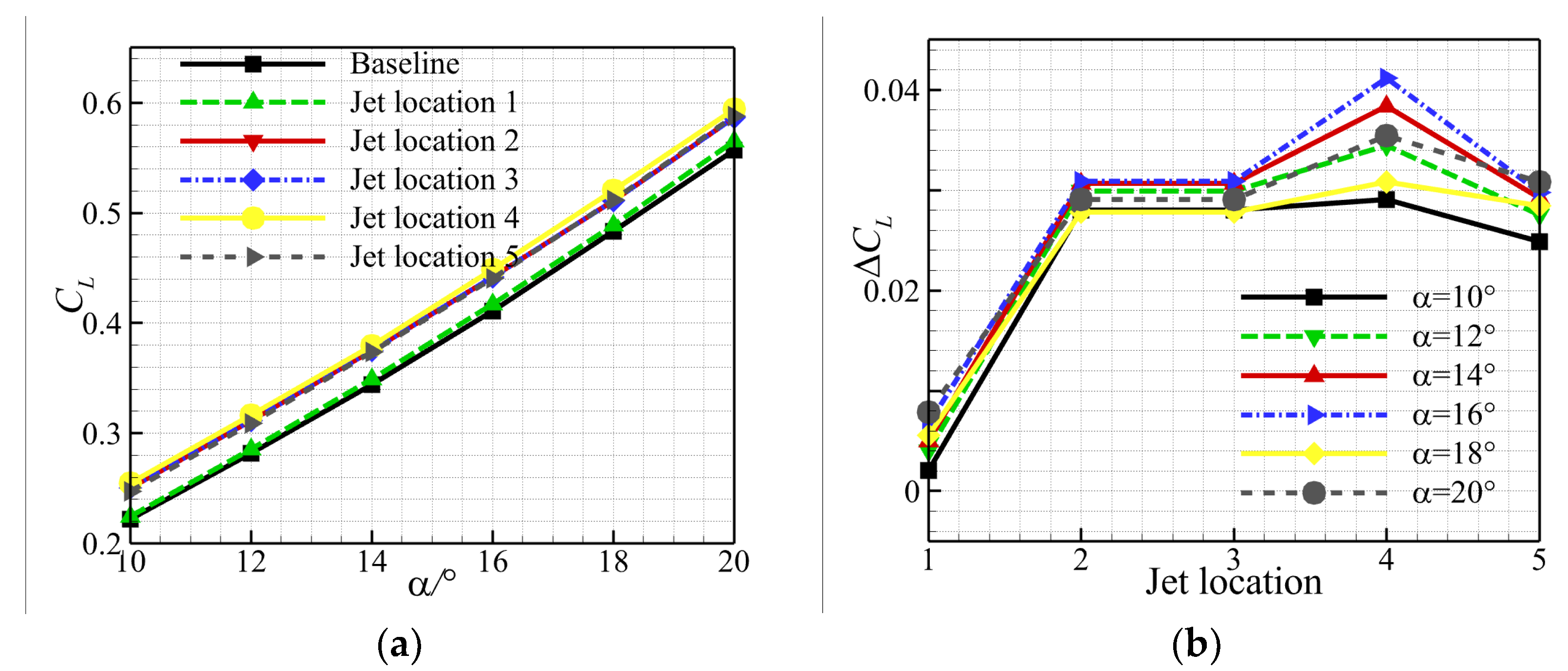
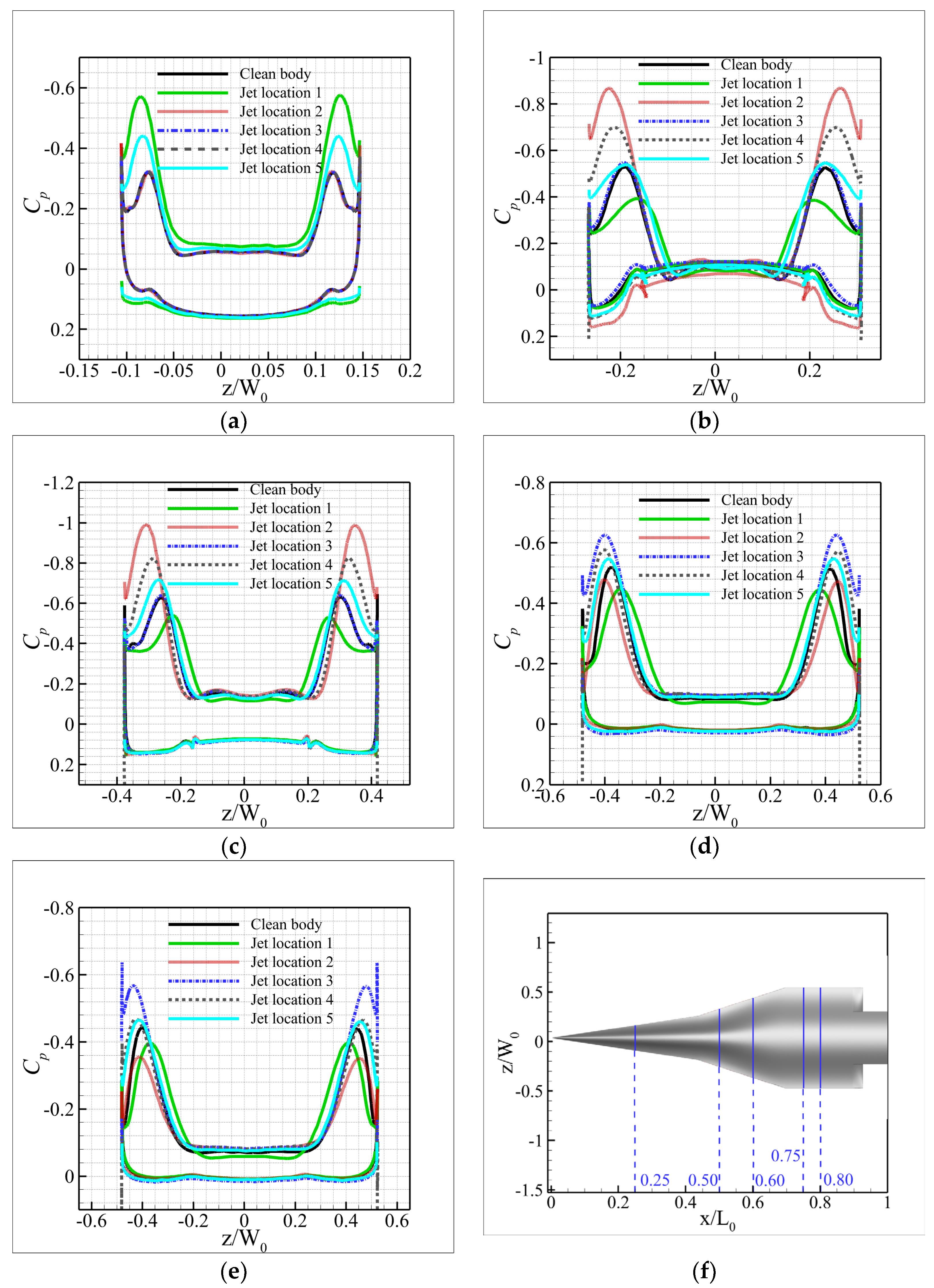
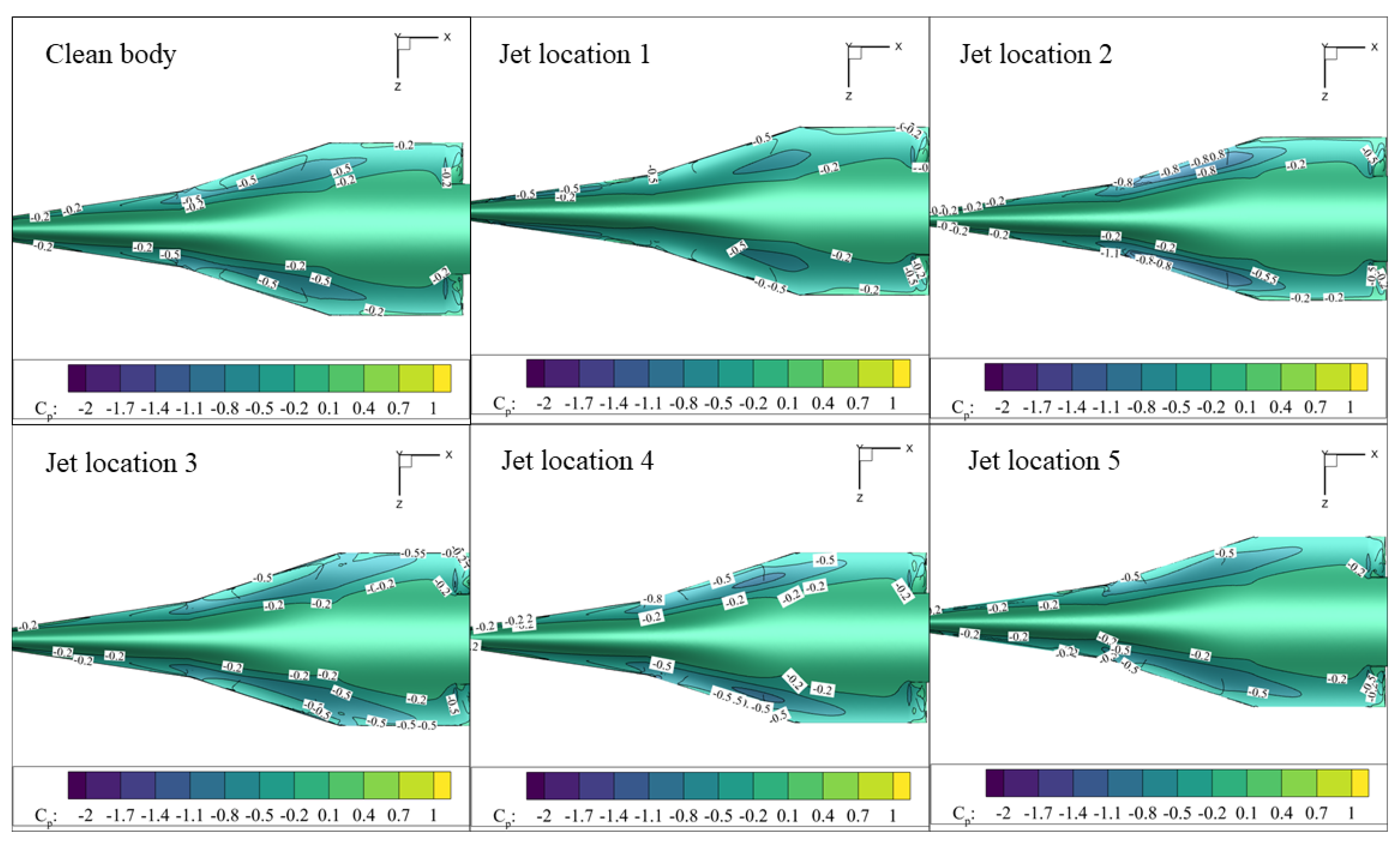
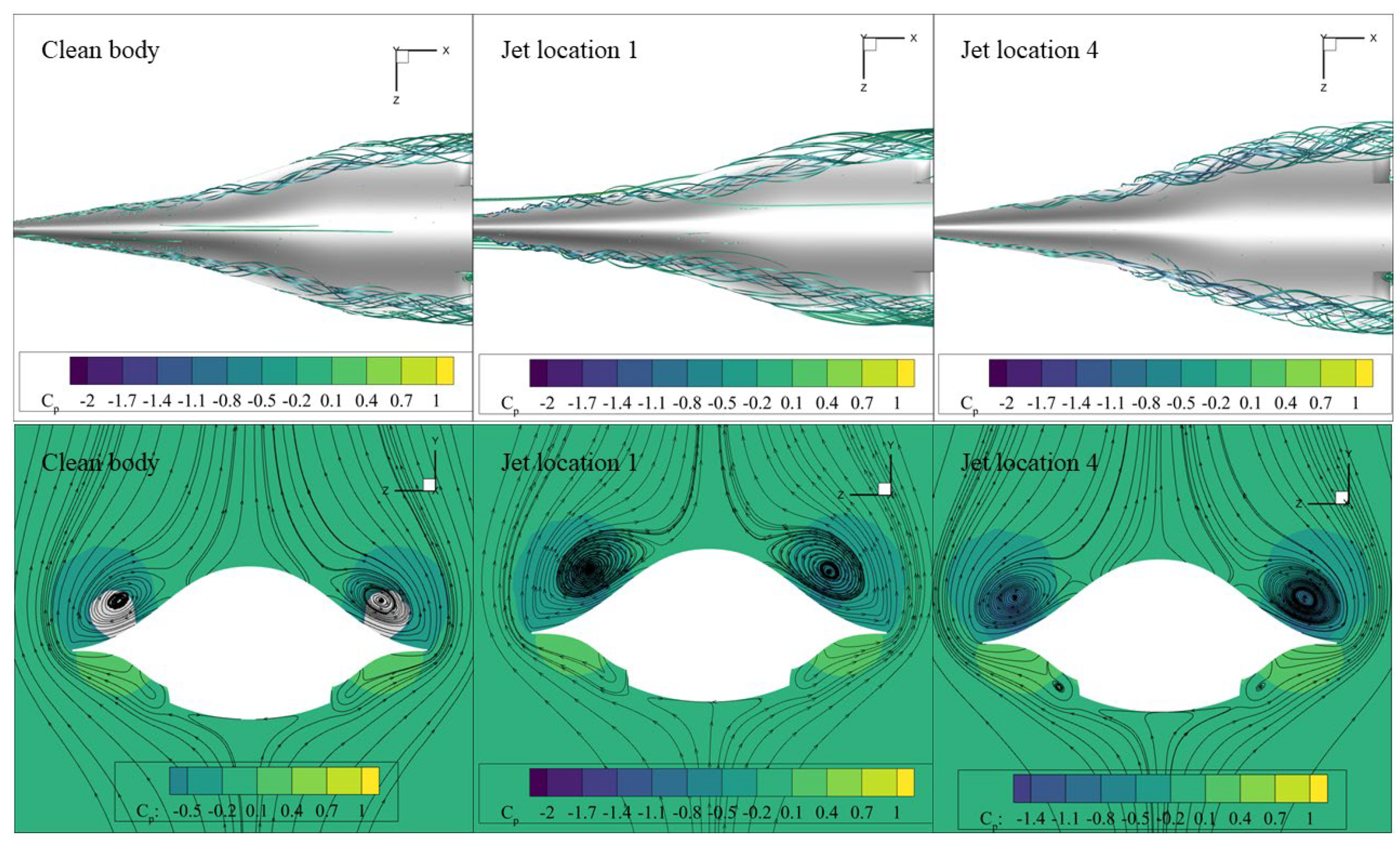
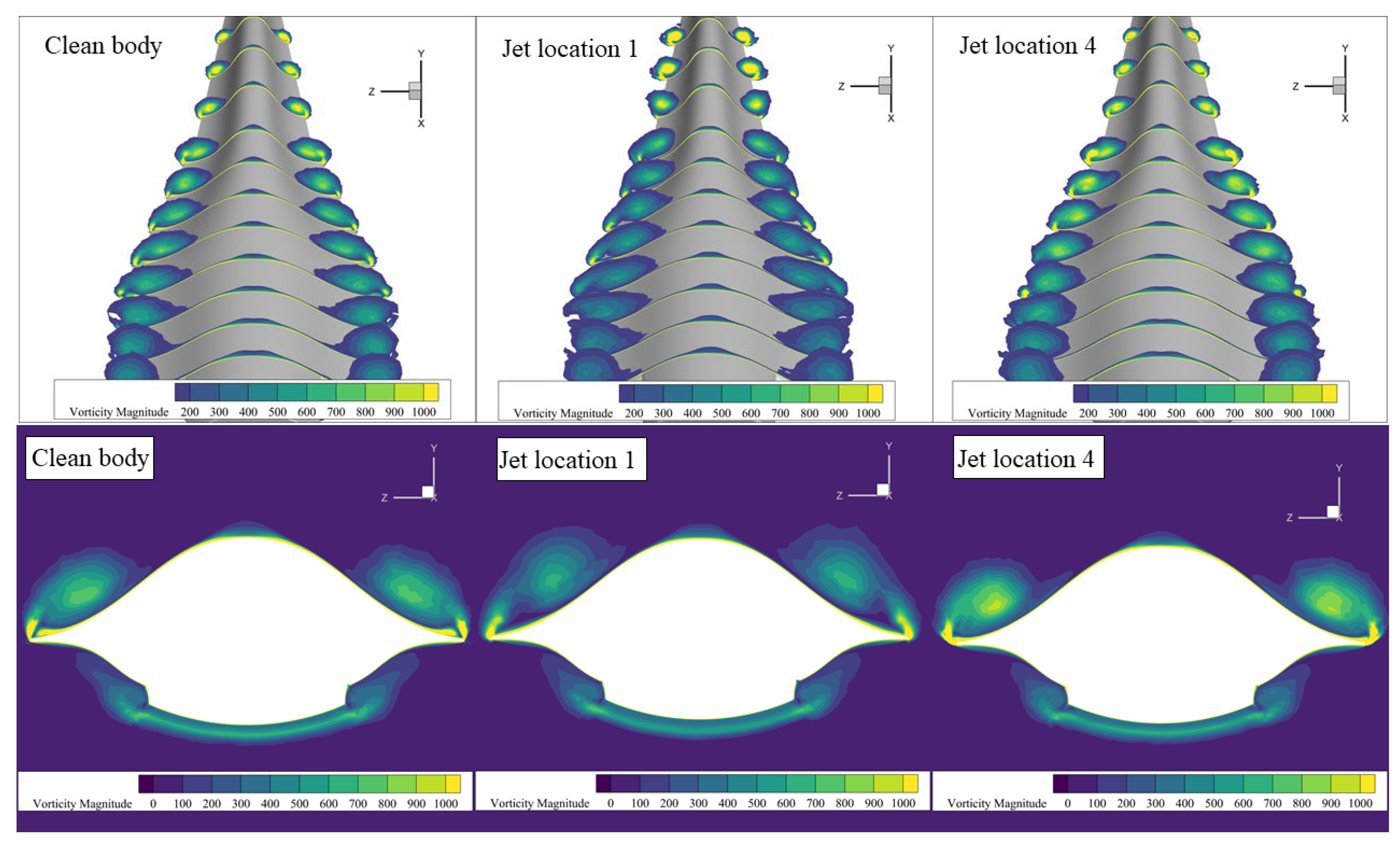
4.1. Effect of Jet Location
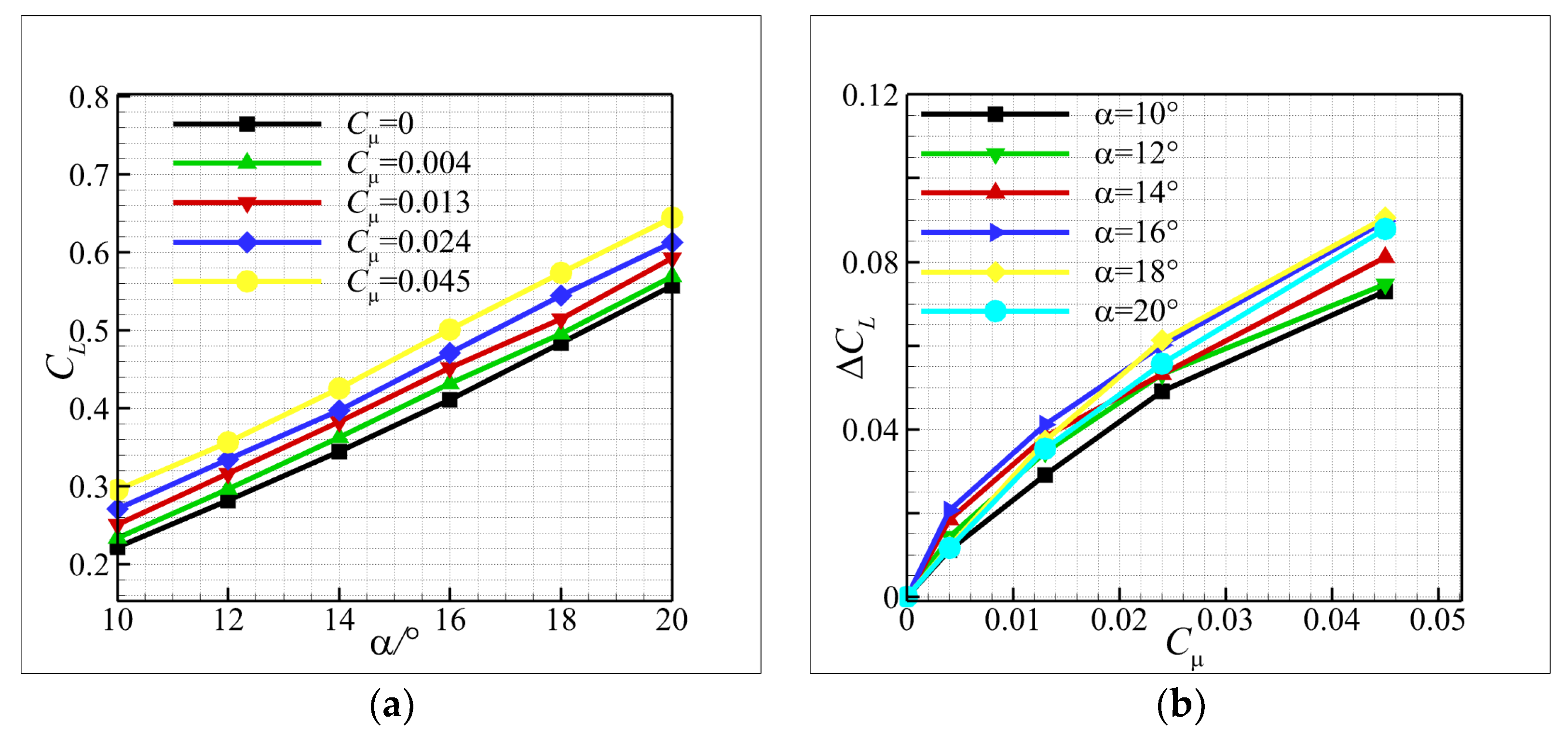
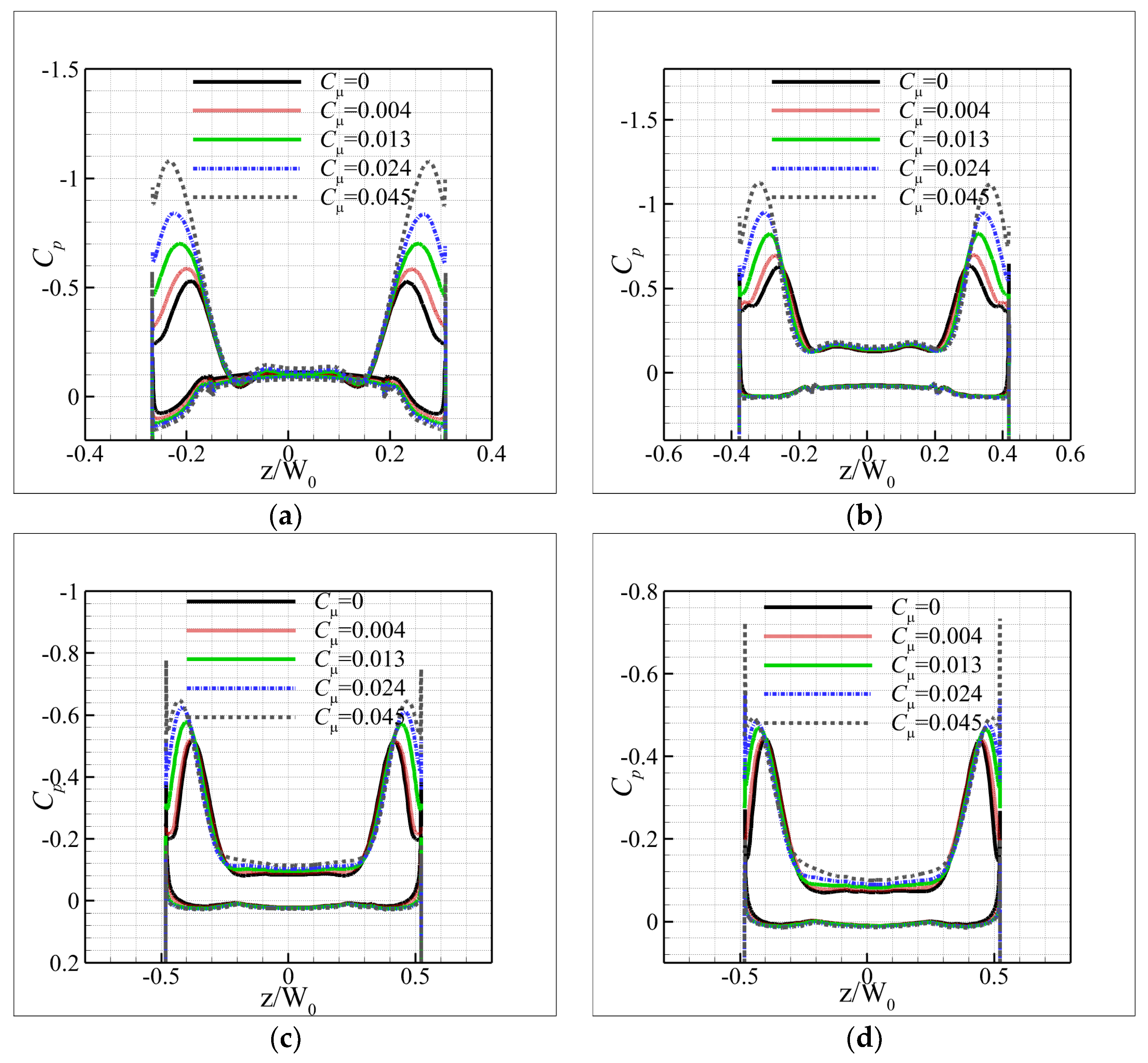
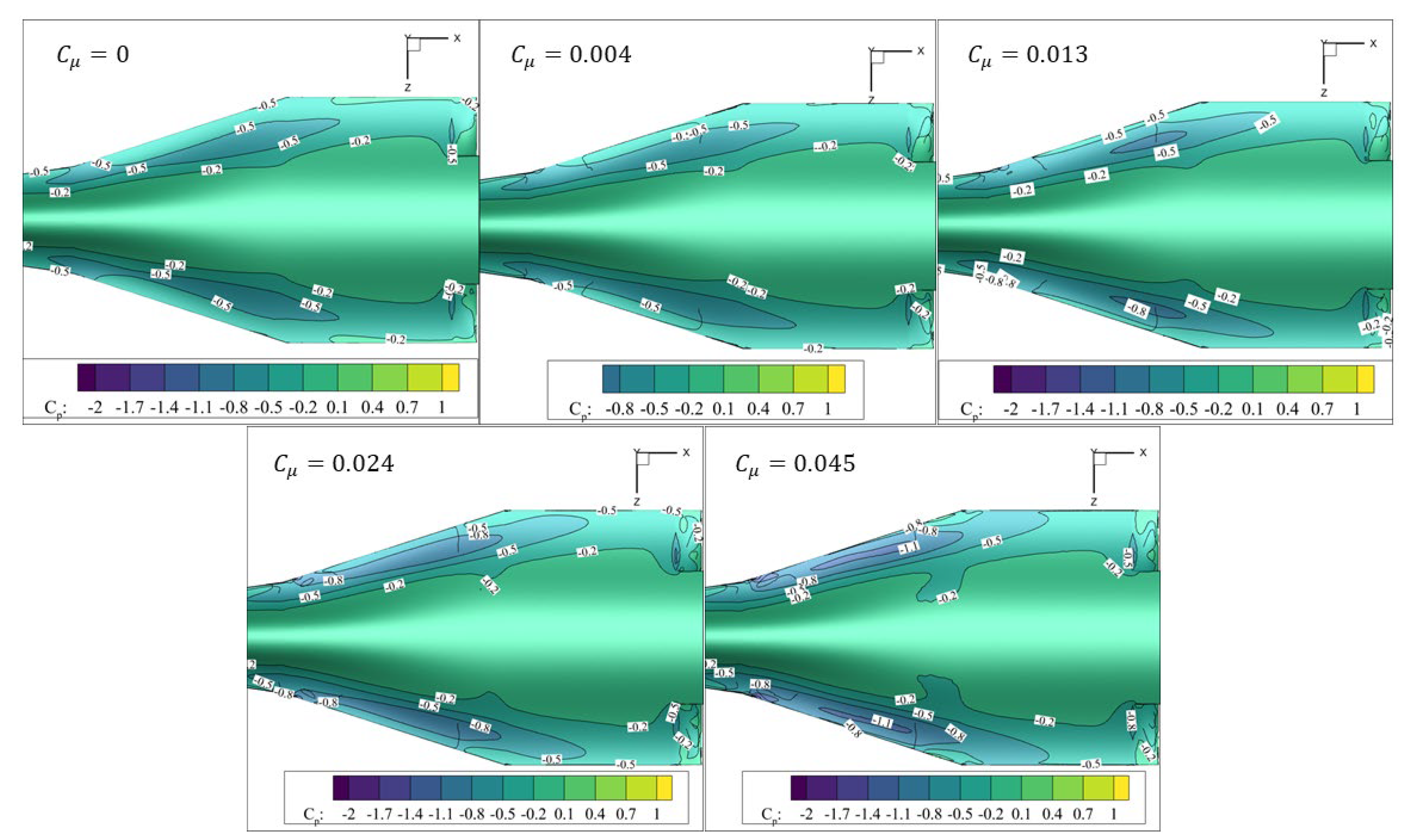
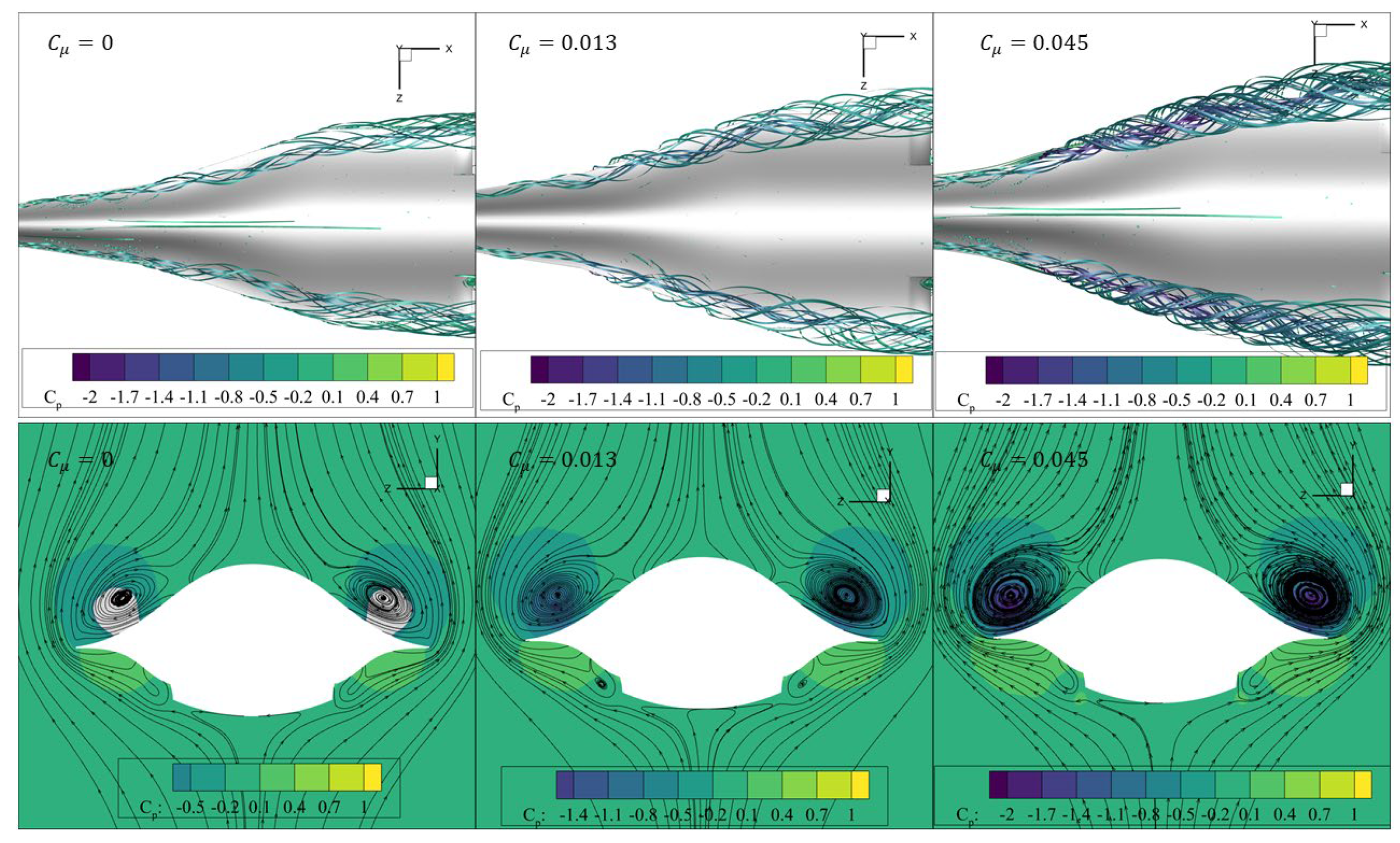
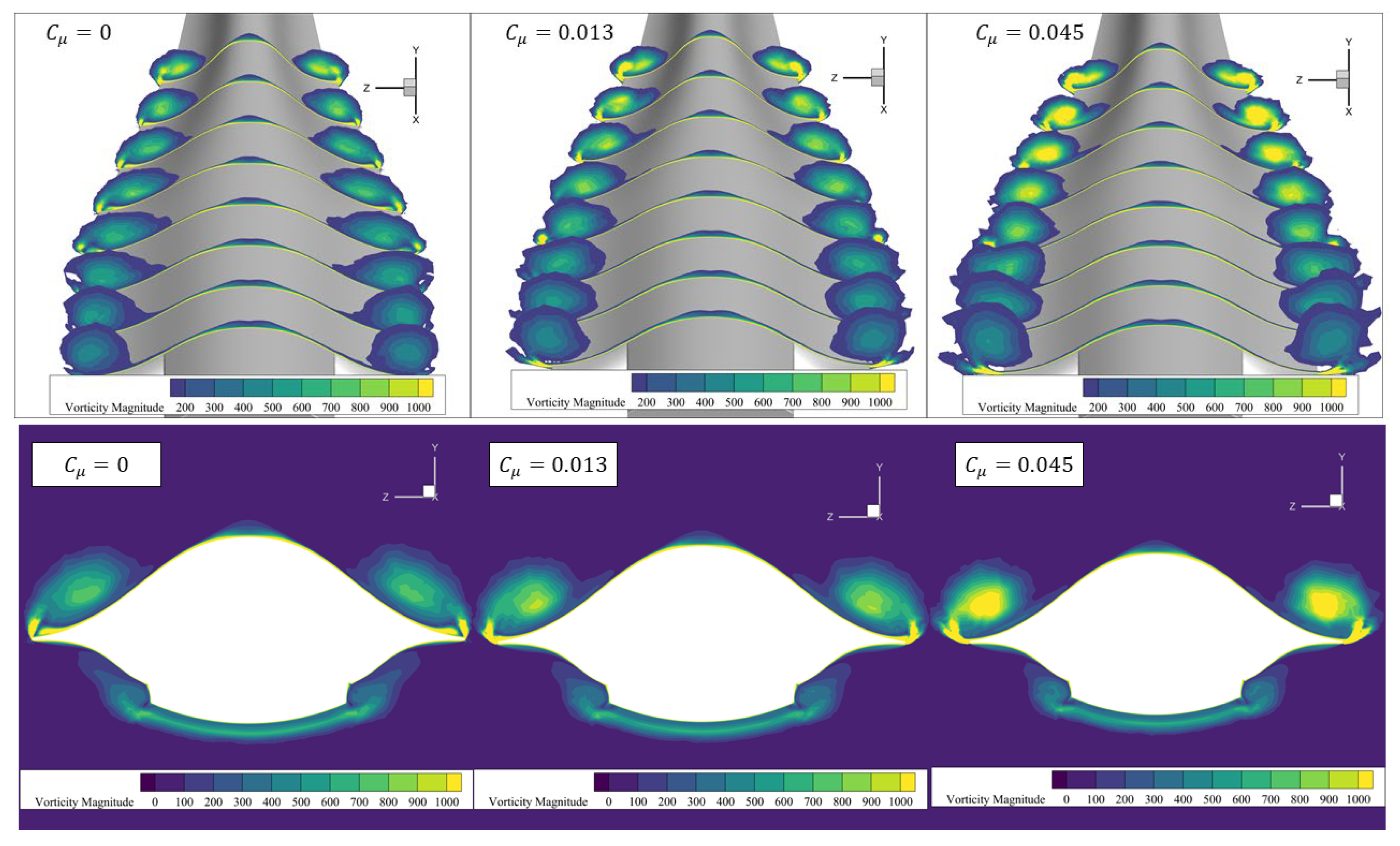
4.2. Effect of Blowing Strength
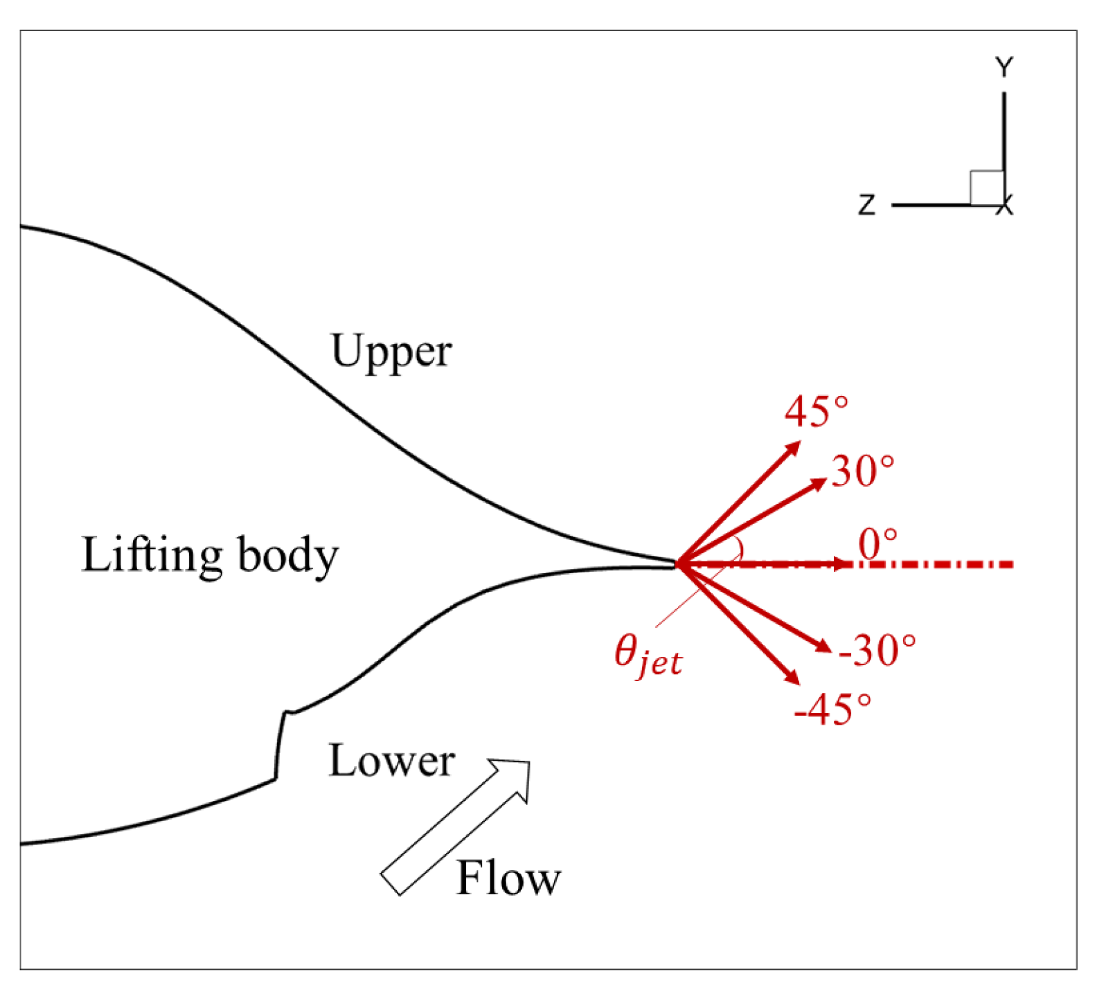
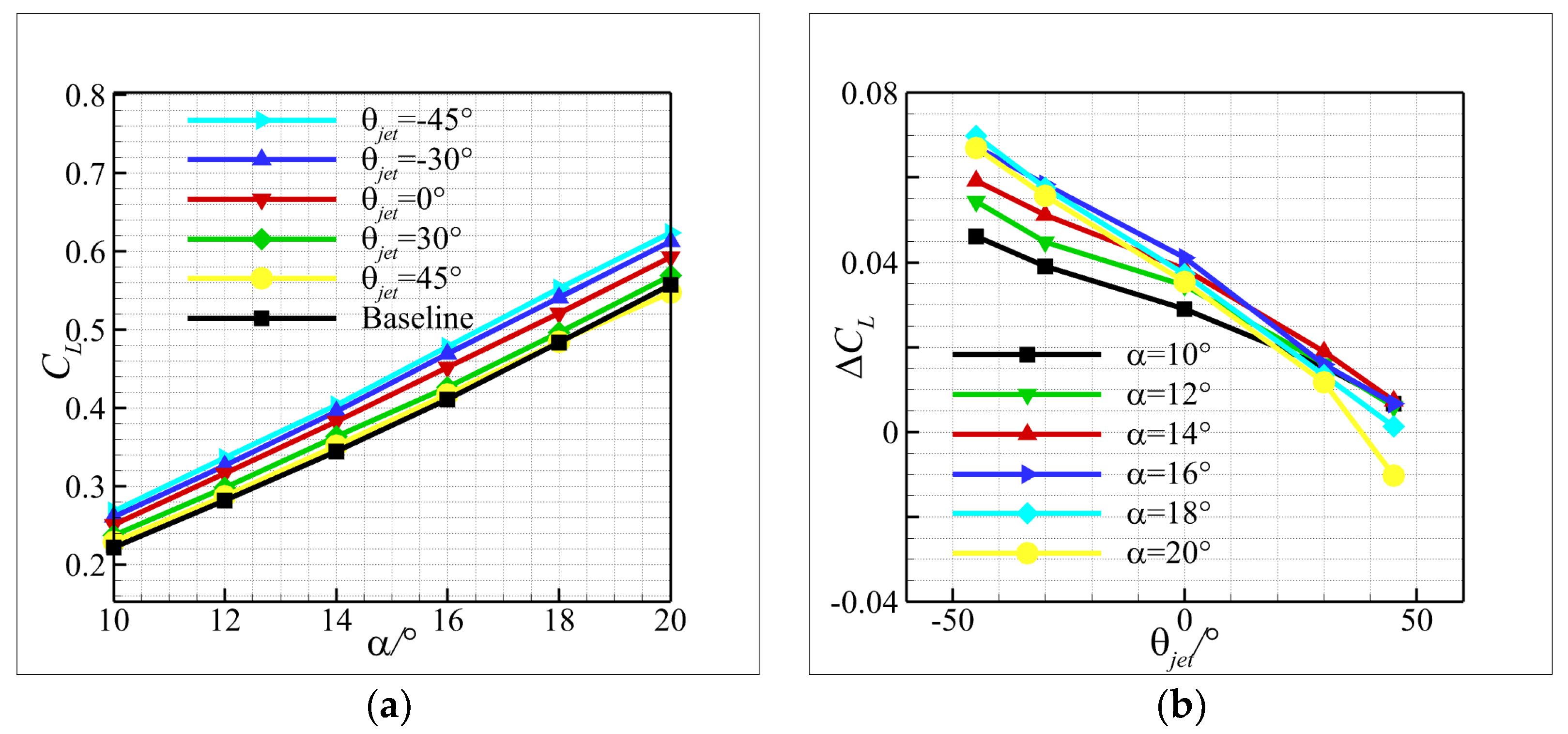
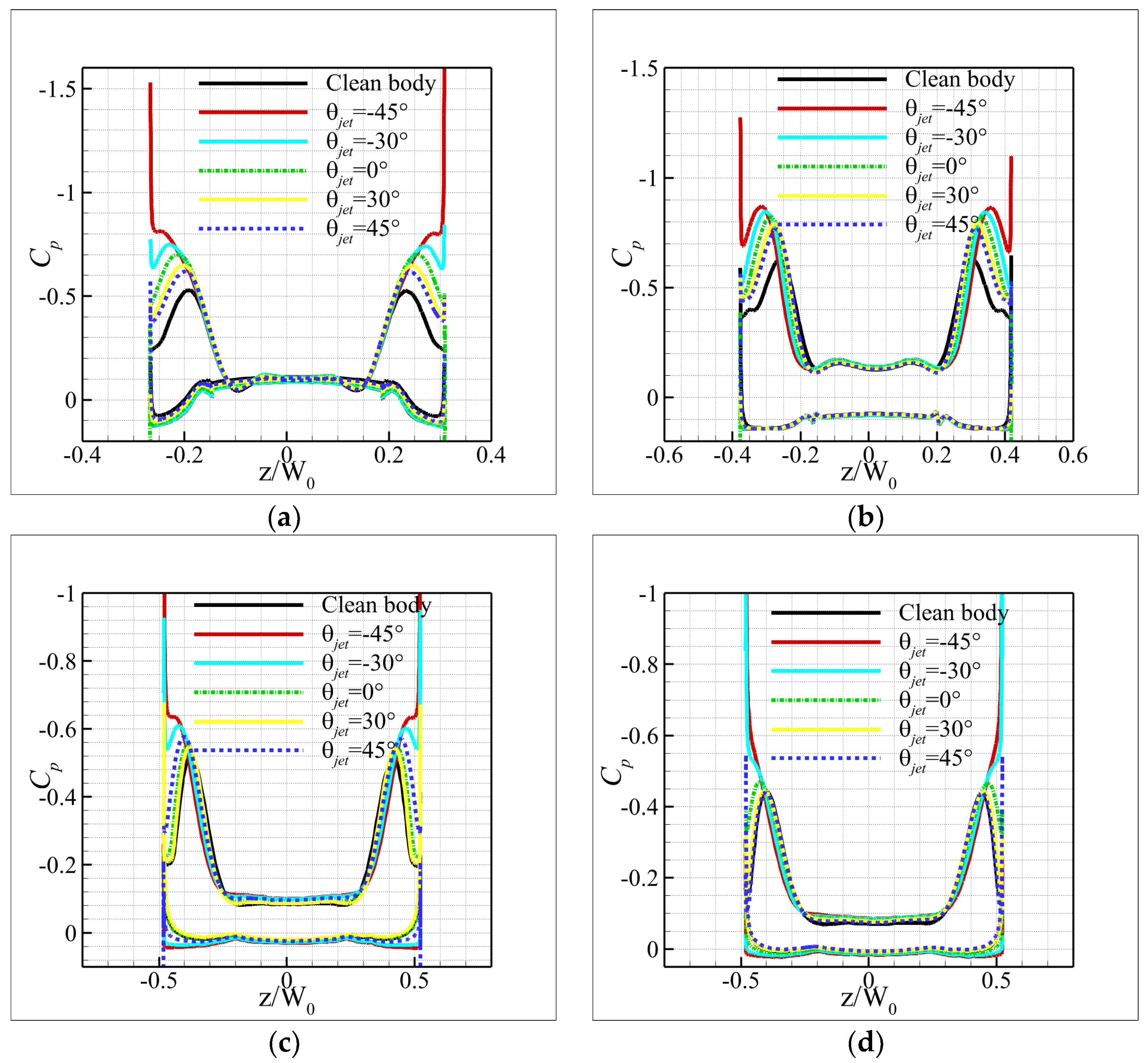
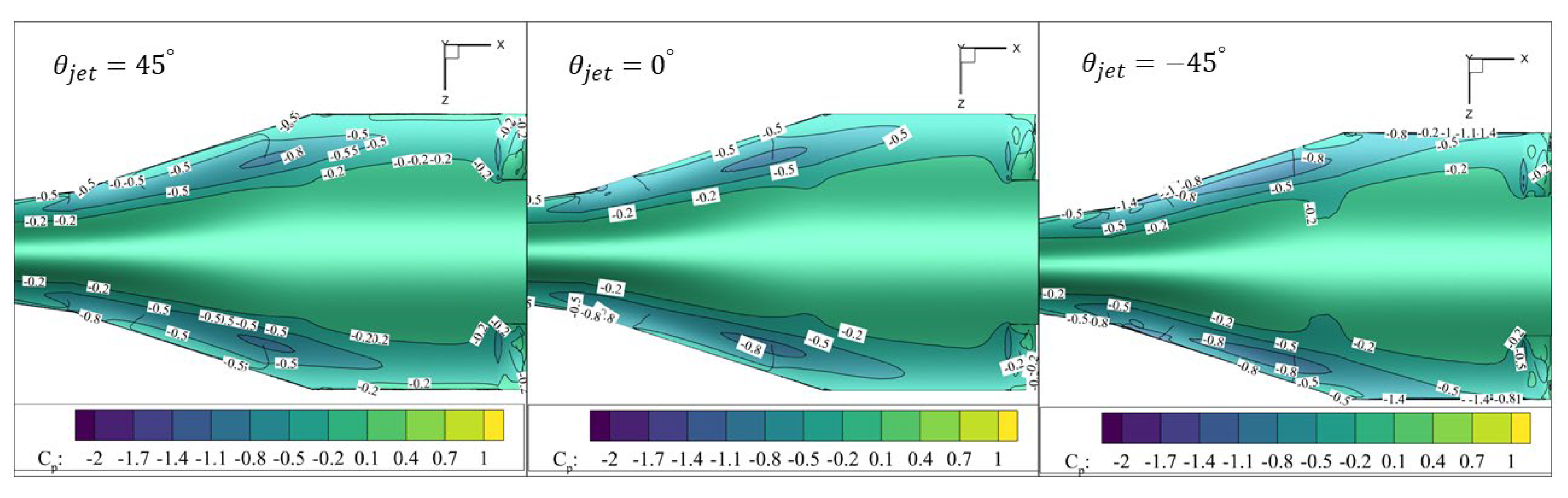
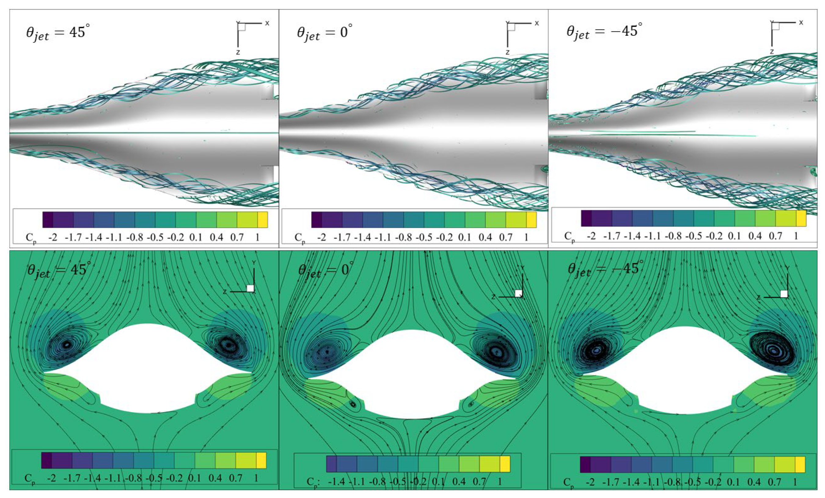
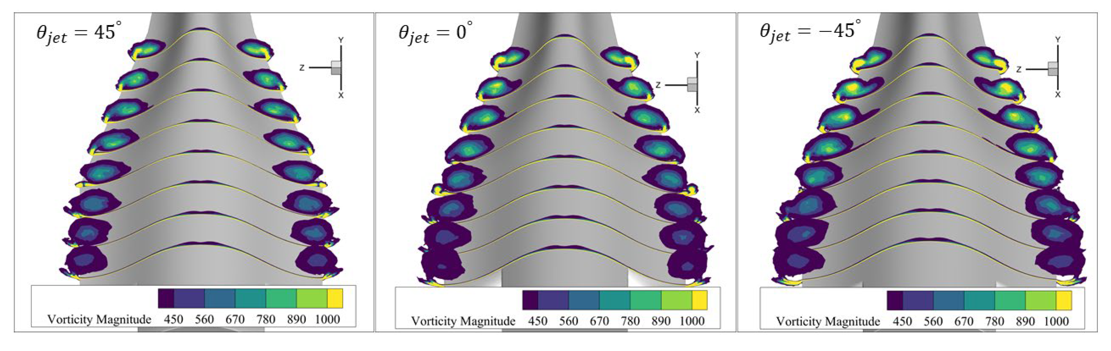
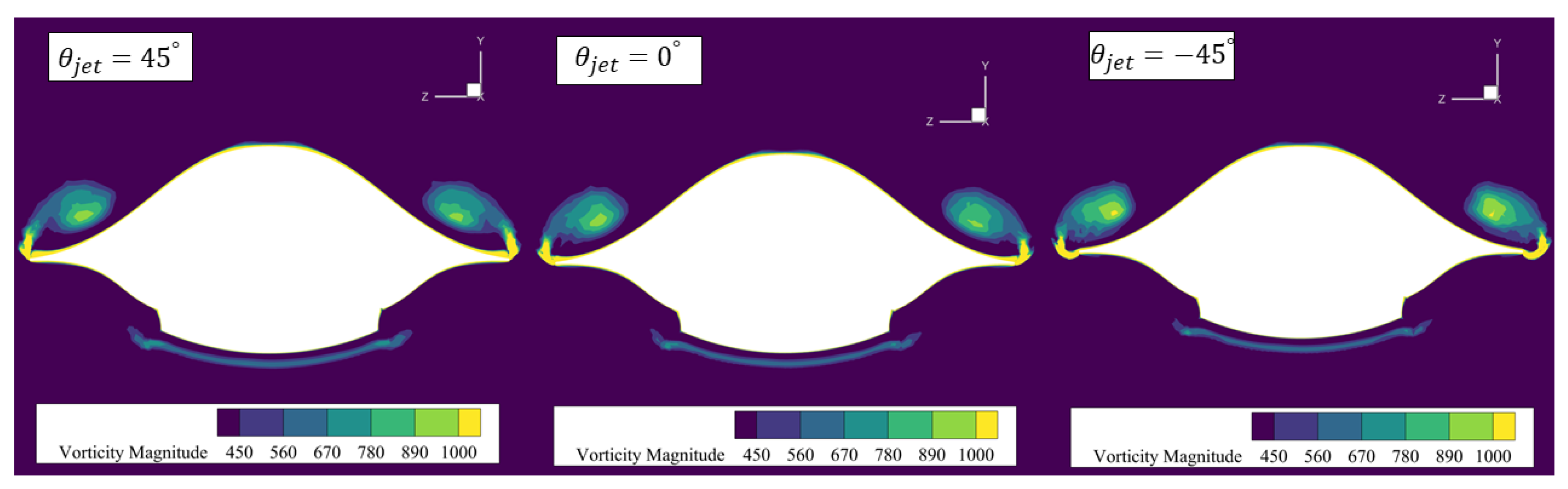
4.3. Effect of Blowing Direction
5. Conclusions
Author Contributions
Funding
Institutional Review Board Statement
Informed Consent Statement
Data Availability Statement
Conflicts of Interest
References
- Sobieczky, H.; Dougherty, F.C.; Jones, K. Hypersonic Waverider Design from given Shock Waves. In Proceedings of the International Hypersonic Waverider Symposium, College Park, MD, USA, 17–19 October 1990. [Google Scholar]
- Rasmussen, M.L. Waverider Configurations Derived from Inclined Circular and Elliptic Cones. J. Spacecr. Rocket. 1980, 17, 537–545. [Google Scholar] [CrossRef]
- Smith, A.M.O. High-Lift Aerodynamics. J. Aircr. 1975, 12, 501–530. [Google Scholar] [CrossRef]
- Staelens, Y.D.; Blackwelder, R.F.; Page, M.A. Computer Simulation of Landing, Takeoff and Go-around of a Blended-Wing-Body Airplane with Belly-Flaps. In Proceedings of the 46th AIAA Aerospace Sciences Meeting and Exhibit, Reno, NV, USA, 7–10 January 2008. [Google Scholar]
- Hummel, D.; Oelker, H. Low-Speed Characteristics for the Wing-Canard Configuration of the International Vortex Flow Experiment. J. Aircr. 1994, 31, 868–878. [Google Scholar] [CrossRef]
- Tu, E.L. Effect of Canard Position on the Longitudinal Aerodynamic Characteristics of a Close-Coupled Canard-Wing-Body Configuration. In Proceedings of the Astrodynamics Conference, Hilton Head Island, SC, USA, 10–12 August 1992. [Google Scholar]
- Luckring, J.M. Aerodynamics of Strake-Wing Interactions. J. Aircr. 1979, 16, 756–762. [Google Scholar] [CrossRef]
- Tian, C.; Li, N.; Gong, G.; Su, Z. A Parameterized Geometry Design Method for Inward Turning Inlet Compatible Waverider. Chin. J. Aeronaut. 2013, 26, 1135–1146. [Google Scholar] [CrossRef]
- Greenblatt, D.; Wygnanski, I.J. Control of Flow Separation by Periodic Excitation. Prog. Aerosp. Sci. 2000, 36, 487–545. [Google Scholar] [CrossRef]
- Zhang, H.; Chen, S.; Meng, Q.; Wang, S. Flow Separation Control Using Unsteady Pulsed Suction through Endwall Bleeding Holes in a Highly Loaded Compressor Cascade. Aerosp. Sci. Technol. 2018, 72, 455–464. [Google Scholar] [CrossRef]
- Li, Y.; Qin, N. Gust Load Alleviation by Normal Microjet. Aerosp. Sci. Technol. 2021, 117, 106919. [Google Scholar] [CrossRef]
- Chan, D.T.; Jones, G.S.; Milholen, W.E.; Goodli, S.L. Transonic Drag Reduction through Trailing-Edge Blowing on the FAST-MAC Circulation Control Model. In Proceedings of the 35th AIAA Applied Aerodynamics Conference, Denver, CO, USA, 5–9 June 2017. [Google Scholar]
- Amitay, M.; Glezer, A. Role of Actuation Frequency in Controlled Flow Reattachment over a Stalled Airfoil. AIAA J. 2002, 40, 209–216. [Google Scholar] [CrossRef]
- Srivastava, B. CFD Analysis and Validation of Lateral Jet Control of a Missile. In Proceedings of the 34th Aerospace Sciences Meeting and Exhibit, Reno, NV, USA, 15–18 January 1996. [Google Scholar]
- Srivastava, B. Computational Analysis and Validation for Lateral Jet Controlled Missiles. J. Spacecr. Rocket. 1997, 34, 584–592. [Google Scholar] [CrossRef]
- Chamberlain, R.; McClure, D.; Dang, A. CFD Analysis of Lateral Jet Interaction Phenomena for the Thaad Interceptor. In Proceedings of the 38th Aerospace Sciences Meeting and Exhibit, Reno, NV, USA, 10–13 January 2000. [Google Scholar]
- Jie, T.; Gong, M.; Sun, X.; Chen, Z.; Liu, F. Numerical Study on Aerodynamic Heating of a Lateral Jet Controlled Rocket. In Proceedings of the AIAA AVIATION 2022 Forum, Chicago, IL & Virtual, USA, 27 June–1 July 2022. [Google Scholar]
- Zhu, L.; Li, Y.; Gong, L.; Chen, X.; Xu, J. Coupled Investigation on Drag Reduction and Thermal Protection Mechanism Induced by a Novel Combinational Spike and Multi-Jet Strategy in Hypersonic Flows. Int. J. Heat Mass Transf. 2019, 131, 944–964. [Google Scholar] [CrossRef]
- Dong, H.; Liu, J.; Chen, Z.; Zhang, F. Numerical Investigation of Lateral Jet with Supersonic Reacting Flow. J. Spacecr. Rocket. 2018, 55, 928–935. [Google Scholar] [CrossRef]
- Jiang, Z.; Liu, Y.; Han, G.; Zhao, W. Experimental Demonstration of a New Concept of Drag Reduction and Thermal Protection for Hypersonic Vehicles. Acta Mech. Sin. Lixue Xuebao 2009, 25, 417–419. [Google Scholar] [CrossRef]
- Erickson, G.E.; Campbel, J.F. Improvement of Maneuver Aerodynamics by Spanwise Blowing; NASA-TP-1065; NASA: Washington, DC, USA, 1978.
- Liu, P.Q.; Wen, R.Y.; Zhang, G.W. Effects of Canard Sweep and Canard-Span Wise Blowing Magnitude on Lift Increment. J. Aircr. 2006, 43, 1369–1371. [Google Scholar] [CrossRef]
- Satran, D.R.; Gilbert, W.P.; Anglin, E.L. Low-Speed Stability and Control Wind-Tunnel Investigation of Effects of Spanwise Blowing on Fighter Flight Characteristics at High Angles of Attack; NASA-TP-2431; NASA: Washington, DC, USA, 1985.
- Hong, J.S.; Roberts, L. A Computational Study on the Effects of Leading Edge Lateral Blowing on Delta Wing Aerodynamics. In Proceedings of the 13th Applied Aerodynamics Conference, San Diego, CA, USA, 19–22 June 1995. [Google Scholar]
- Hong, J.S.; Çelik, Z.Z.; Roberts, L. Effects of Leading-Edge Lateral Blowing on Delta Wing Aerodynamics. AIAA J. 1996, 34, 2471–2478. [Google Scholar] [CrossRef]
- Kamishita, M.; Aso, S.; Karashima, K.; Sato, K. Active Control of Aerodynamic Chracteristics of Next-Generation SST Wing by Lateral Blowing. In Proceedings of the 38th Aerospace Sciences Meeting and Exhibit, Reno, NV, USA, 10–13 January 2000. [Google Scholar]
- Kamishita, M.; ASO, S.; Kamishita, K.; Sato, K. A Study on Improvement of Aerodynamic Characteristics of the Next-Generation SST Wing by Lateral Blowing in Subsonic Flow. J. Jpn. Soc. Aeronaut. Space Sci. 2001, 49, 174–180. [Google Scholar] [CrossRef]
- Aso, S.; Kamishita, M.; Karashima, K.; Sato, K. A Study on Active Flow Control for Next-Generation SST for Higher L/D. In Proceedings of the 32nd AIAA Fluid Dynamics Conference and Exhibit, St. Louis, MO, USA, 24–26 June 2002. [Google Scholar]
- Tadakuma, K.; Aso, S.; Ishida, T.; Tani, Y.; Nakawatase, R. Lift Augmentation by Lateral Blowing for RLVs with Various Fuselage-Cross Sections. In Proceedings of the Collection of Technical Papers—3rd AIAA Flow Control Conference, San Francisco, CA, USA, 5–8 June 2006. [Google Scholar]
- Muramatsu, S.; Okada, S.; Hiraoka, K. Numerical Analysis of Control of Leading-Edge Vortex on Delta Wing with Blowing. In Proceedings of the 23rd AIAA Applied Aerodynamics Conference, Toronto, ON, Canada, 6–9 June 2005. [Google Scholar]
- Zhang, J.M.; Cai, J.; Cui, Y. Effect of Nozzle Shapes on Lateral Jets in Supersonic Crossflows. In Proceedings of the 47th AIAA Aerospace Sciences Meeting including the New Horizons Forum and Aerospace Exposition, Orlando, FL, USA, 5–8 January 2009. [Google Scholar]
- Doolabi, M.H.; Sabour, S.A.T. An Experimental Study of Binary Lateral Jets on a Standard Model in Subsonic, Transonic, and Supersonic Cross-Flows. Proc. Inst. Mech. Eng. Part G J. Aerosp. Eng. 2019, 233, 3141–3152. [Google Scholar] [CrossRef]
- Menter, F.R. Two-Equation Eddy-Viscosity Turbulence Models for Engineering Applications. AIAA J. 1994, 32, 1598–1605. [Google Scholar] [CrossRef]
- Menter, F.R.; Kuntz, M.; Langtry, R. Ten Years of Industrial Experience with the SST Turbulence Model. Heat Mass Transf. 2003, 4, 625–632. [Google Scholar]
- Brunner, M.S.; Blaylock, M.; Cooperman, A.M.; Van Dam, C.P. Comparison of CFD with Wind Tunnel Tests of Microjets for Active Aerodynamic Load Control. In Proceedings of the 50th AIAA Aerospace Sciences Meeting including the New Horizons Forum and Aerospace Exposition, Nashville, TN, USA, 9–12 January 2012. [Google Scholar]
- Nelms, W.P.; Thomas, C.L. Aerodynamic Characteristics of an All-Body Hypersonic Aircraft Configuration at Mach Numbers from 0.65 to 10.6; NASA Technical Note D-6577; NASA: Washington, DC, USA, 1971.
- Boeije, C.S.; De Vries, H.; Cleine, I.; Van Emden, E.; Zwart, G.G.M.; Stobbe, H.; Hirschberg, A.; Hoeijmakers, H.W.M. Fluidic Load Control for Wind Turbine Blades. In Proceedings of the 47th AIAA Aerospace Sciences Meeting including the New Horizons Forum and Aerospace Exposition, Orlando, FL, USA, 5–8 January 2009. [Google Scholar]
- Lefebvre, A.; Dano, B.; Bartow, W.B.; Difronzo, M.; Zha, G.C. Performance and Energy Expenditure of Coflow Jet Airfoil with Variation of Mach Number. J. Aircr. 2016, 53, 1757–1767. [Google Scholar] [CrossRef]


| Geometric Parameters | Value |
|---|---|
| 0.5397 m | |
| 0.3114 m | |
| 5.675 m2 |
| Grid Type | Number of Grid Points | Number of Cells for Each Jet | |
|---|---|---|---|
| coarse grid | 9.7 million | 501 × 7 | 0.57 |
| medium grid | 21 million | 801 × 13 | 0.52 |
| fine grid | 38 million | 1201 × 17 | 0.44 |
| 0.000 | 0.00% |
| 0.013 | 1.14% |
| 0.045 | 4.05% |
Publisher’s Note: MDPI stays neutral with regard to jurisdictional claims in published maps and institutional affiliations. |
© 2022 by the authors. Licensee MDPI, Basel, Switzerland. This article is an open access article distributed under the terms and conditions of the Creative Commons Attribution (CC BY) license (https://creativecommons.org/licenses/by/4.0/).
Share and Cite
Wang, H.; Liu, J.; Deng, F.; Li, G.; Ding, Y.; Xia, Q.; Zhang, F. Lift Augmentation at Subsonic Speeds by Lateral Jets for a Hypersonic Aircraft. Aerospace 2022, 9, 745. https://doi.org/10.3390/aerospace9120745
Wang H, Liu J, Deng F, Li G, Ding Y, Xia Q, Zhang F. Lift Augmentation at Subsonic Speeds by Lateral Jets for a Hypersonic Aircraft. Aerospace. 2022; 9(12):745. https://doi.org/10.3390/aerospace9120745
Chicago/Turabian StyleWang, Haifeng, Jianxia Liu, Feng Deng, Guoshu Li, Yunguang Ding, Qiang Xia, and Fan Zhang. 2022. "Lift Augmentation at Subsonic Speeds by Lateral Jets for a Hypersonic Aircraft" Aerospace 9, no. 12: 745. https://doi.org/10.3390/aerospace9120745
APA StyleWang, H., Liu, J., Deng, F., Li, G., Ding, Y., Xia, Q., & Zhang, F. (2022). Lift Augmentation at Subsonic Speeds by Lateral Jets for a Hypersonic Aircraft. Aerospace, 9(12), 745. https://doi.org/10.3390/aerospace9120745