Article

Investigations on an All-Oxide Ceramic Composites Based on Al2O3 Fibres and Alumina–Zirconia Matrix for Application in Liquid Rocket Engines

by
Christian Bach
1,*,†,
Frank Wehner
2,† and
Jan Sieder-Katzmann
1,†
1
Institute of Aerospace Engineering, Technische Universität Dresden, 01062 Dresden, Germany
2
Walter E.C. Pritzkow Spezialkeramik, 70794 Filderstadt, Germany
*
Author to whom correspondence should be addressed.
These authors contributed equally to this work.
Aerospace 2022, 9(11), 684; https://doi.org/10.3390/aerospace9110684
Submission received: 1 September 2022 / Revised: 10 October 2022 / Accepted: 20 October 2022 / Published: 3 November 2022
(This article belongs to the Special Issue Liquid Rocket Engines)

Abstract

:
High performance ceramics, particularly Ceramic Matrix Composite (CMC) materials found their way into liquid rocket engines. Yet, so far, mainly carbide or nonoxide CMCs have been of interest. This paper explores the potential and challenges of oxide–oxide ceramic matrix composites (OCMCs) for application in rocket thrust chambers. Therefore, strength, leakage and hot gas tests are conducted with material samples. A particular focus lies on the application of coatings to seal the permeability inherent to the material. Furthermore, prototypes in the form of flame tubes, ceramic chambers with nozzles and ceramic chambers with graphite inlays are developed and investigated experimentally in test firings. The results show that a recrystallised glass of a Y-Al-Si-O compound can successfully create an impermeable coating of the OCMC without affecting its damag-tolerant behaviour. However, the prototype developments show that it is still very challenging to manufacture even slightly complex structures without critical failures. Nevertheless, OCMC structures of relatively simple geometries showed promising results in hot firings and could be used as a lightweight housing, while the inner contour of the chamber and nozzle are realised, e.g., by a graphite inlay of appropriate quality.

Graphical Abstract

1. Introduction

Combustion chamber materials have to withstand the highest thermal and structural loads, which regularly leads to the use of high-tech metal alloys and rare-earth metals that have the drawback of high costs and manufacturing effort. Relevant material properties do not only include thermo-mechanical properties, but also need to comply with requirements such as compatibility with cryogenic propellants, high-temperature, chemical corrosion, oxidation resistance, high thermal conductivity, high restistance against thermal shocks and abrasion restistance to withstand high-enthalpy flows, to name a few.
As an alternative to metals, high-performance ceramics are not new to the aerospace industry. Ceramic coatings using ZrO 2 have been successfully deployed in Ariane 4’s Viking Engine, which also utilised fibre-reinforced graphite in the supersonic part of its nozzle. Furthermore, the third stage of Ariane 4 had an extension nozzle made out of C/SiC. This development has been continued with the Vinci Engine in Ariane 5, which also utilises the advantages of a CMC nozzle extension. Further, note the Space Shuttle Orbiter, whose Thermal Protection System (TPS) mainly relied on C/SiC tiles with a borosilicate coating. Together with the application potential in super- and hypersonic flight vehicles, the fields where aerospace can benefit from ceramic technology can be summarised as propulsion and exhaust washed structures, thermal protection systems and hot primary structure [1,2,3].
In the recent past, Ceramic Matrix Composite (CMC) materials even found their way into combustion spaces. Schmidt et al. [4] successfully tested an uncooled C/SiC rocket engine for 8900 s under nominal conditions. Furthermore, the Prospector 10 rocket from Garvey Spacecraft Corporation in collaboration with California State University Long Beach had an aerospike engine with 10 clustered CMC combustion chambers made of high temperature composites. The rocket actually flew but could not be recovered.
So far, mainly carbide or nonoxide CMCs have been of interest. However, the overall result for even the most mature systems is that a thorough understanding does not exist of the resulting microstructures to be predictive on component life nor a method to document the specific damage accumulation mechanisms that fully account for the tensile, compression, shear, creep, fatigue and oxidation performance of the materials [2]. Currently, multiple studies are ongoing to tackle this challenge.
Another class of advanced ceramics are Oxide–oxide Ceramic Matrix Composites (OCMCs), which are less well investigated than its carbide counterparts. Yet, there are also some major technology innovations utilising their application advantages. One of the most impressive ones is Boing’s OCMC Acoustic nozzle, an alumina-fibre-reinforced aluminosilicate matrix composite primary exhaust nozzle, which has already been flown succesfully as a prototype system and reached a Technology Readiness Level (TRL) of 7 [2,5]. Another example is the Shefex II mission, which is primarely a reentry experiment for new TPS technologies. Here, besides C/C-SiC and C/SiC components, OCMC tiles have also been integrated. Namely, WHIPOX, a technology development of the German Space Agency (DLR) was used, utilising its electromagnetic transparency to open a telemetry window in the otherwise shielding carbide TPS. More recently, it served as the TPS for the safe reentry of the flight recorder of the latest ATV-5 mission [6].
OCMCs have also been integrated in combustion spaces, foremost by Ortelt et al. [7], who succesfully developed and tested an effusion cooled C/C combustion chamber. However, due to oxidation problems, they had to implement an OCMC component, in particular, adjacent to the injector, where a high amount of unburnt oxygen is expected [7]. Furthermore, as effusion cooled, this material could excellently demonstrate its oxidation resistance under high performance conditions pc = 60 bar in a 50 mm demonstrator, in tests up to 120 s [7]. This application shows the main advantage of OCMCs over nonoxide CMCs: while generally providing a lower high temperature strength, any oxidation problems are eliminated [8].
Moreover, Ortelt et al. [7] took advantage of the OCMC’s porosity and permeability to design a cone injector, which consists of an alternating concentric ring-gap system with a cone body inlay made of a robust OCMC, namely FW12. It is based on aluminum oxide fibers and a matrix. “Foundation for this material are a bimodal grain size distribution of the used ceramic powder, an optimal ration of alumina and zirconia powder, the weak-matrix concept of fiber-reinforced ceramics and a rheological adapted suspension to the processing technology” [9]. So far, this injector has only been tested in cold-flow tests.
This material, FW12, is the basis for the present work. It is primarely used for industrial applications such as furnace construction and hot gas piping systems. Here, its applicability to Liquid-Propellant Rocket Engines (LPREs) is investigated. The utilisation of OCMC is investigated within a conventional thrust chamber of the 500 N class, running on ethanol and Liquid Oxygen (LOX). Therefore, the material properties and the exploration of its development and operation are presented. The objective of this work is to provide insights in the potential and challenges inherent to the use of OCMCs for space propulsion applications.

2. Materials and Methods

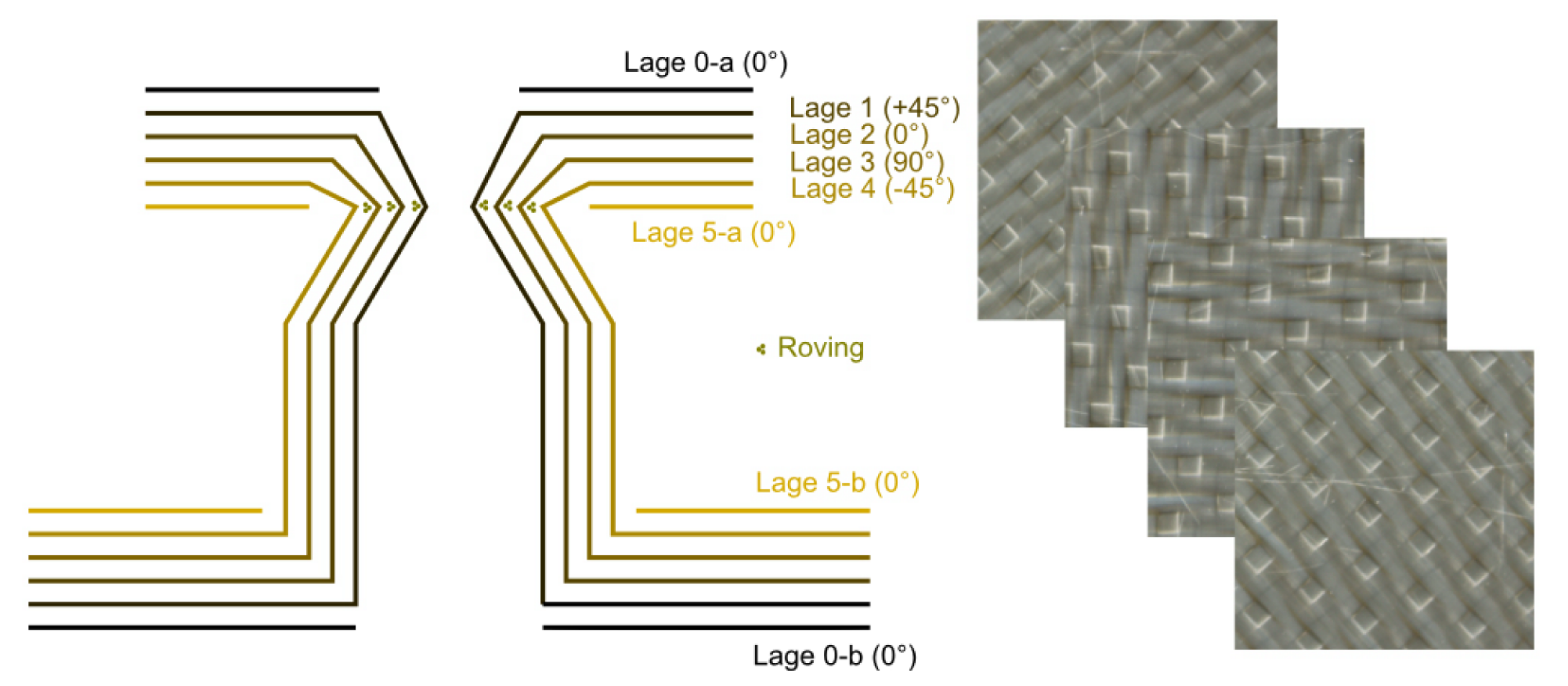
2.1. Material Properties

As introduced in the previous section, previous publications regarding fibre-reinforced ceramics in combustion chambers mainly refer to non-oxidic CMCs. In such applications, the problem of oxidation is often solved by creating a non-oxidising atmosphere near the combustion chamber wall. This is realised, for example, by transpiration cooling with fuel, which establishes a fuel-rich combustion zone close to the combustion chamber wall. An alternative solution is the application of an oxidation-resistant coating. However, the implementation of a combustion chamber with an OCMC has not yet been described in the technical literature. This was the motivation to investigate this high temperature resistant, damage tolerant and oxidation resistant material in more detail. In this subsection, the material properties of OCMCs FW12 are presented and examined in more detail in application-oriented, experimental investigations. The tests performed include 4-point bending tests, manufacturing process investigations, thermal shock tests and practical analyses of ductility, density and porosity. Table 1 shows the composition of OCMC FW12.
The collected material properties of the OCMC FW12 are displayed in Table 2. This material is primarily used for industrial applications in plant engineering, for example, in furnaces or hot gas pipe systems. The manufacturing process used here was based on fabric that is commercially available. The fabric was cut to size. Before the fabric could be processed further, the sizing had to be reduced. For this purpose, a thermal pre-treatment at 800 °C was carried out. The individual fabric layers were then infiltrated with the slurry by hand using knife coating. Next, they were applied to a paraffin-coated mould. Then, the material was dried on that mould in a furnace at 80 °C. After demoulding, the ceramic green body was carefully machined. It was then sintered at 1200 °C with a dwell time of 5 h. The final part was further processed with diamond tools.
One of the most important material properties of CMC is its morphology in terms of homogeneous porosity and permeability. These characteristics are of particular importance as they are responsible for the excellent damage tolerance and shock resistance of CMCs. In contrast to monolithic ceramics, reinforcement with fibres leads to a crack growth process described by Levi et al. [10] as a weak matrix concept, leading to higher material strength as the reinforcing fibres remain intact. The key to this behaviour lies in the porous matrix, which, as shown in Figure 1, leads to a deflection of the cracks along the fibre direction. In addition, the reinforcing fibres bridge the damaged matrix as the crack propagates. This results in a force acting on the crack flanks, which counteracts the widening of the crack. However, if the strength of the reinforcing fibres is exceeded, they also crack, but usually not in the plane in which the crack occurred. Accordingly, the ends of the reinforcing fibres are pulled out of the surrounding matrix, dissipating energy and consequently reducing crack growth. This mechanism, known as fibre pullout, results in a damage pattern shown in Figure 2.
The porosity of the material can also be used profitably to apply transpiration cooling. For this purpose, the thrust chamber must be designed as a double wall. The inner wall, facing the combustion chamber, has fuel flowing through it, while the outer wall seals against the environment. However, a tight outer wall cannot be implemented with a permeable CMC. Ortelt et al. solve this by making the outer shell of their engine out of Carbon Fibre Reinforced Plastic (CFRP). However, this has the consequence that the assembly of the inner and outer components has to be realised via relatively heavy metal flanges, which at least partially cancel out the weight savings due to the CMC use.
The use of an impermeable CMC would be obvious. In principle, there are two ways to make the basically porous and thus permeable CMC impermeable. The first possibility is to completely avoid pores in the matrix. However, this reduces the resistance to thermal shock and the damage tolerance of the material in accordance with the previously described material behaviour. The material properties of the composite could only be maintained if not the matrix but the interface between the reinforcing fibres and the matrix were weakened. The advantageous crack growth properties would be maintained, while the matrix could be compacted to the extent that the CMC would become impermeable. This second way of influencing the interface between reinforcing fibres and matrix can be realised by coating the fibres. However, this represents a time-consuming and cost-intensive process that influences the entire production chain.
An alternative to these processes is to leave the underlying material unchanged and apply an impermeable coating to the CMC. The main challenge in this process is to match the properties of the coating to be developed, as these must exactly match the specifications of the CMC in order not to negatively affect the desired performance of the material. For the present OCMC FW12, a coating of recrystallised glass of a Y-Al-Si-O compound was used, which has no residual glass phases. The coating had a thickness of 200 µm. Unlike coatings of materials made of C/SiC to avoid oxidation effects, which fall under the class of Environmental Barrier Coatings (EBCs), OCMC are mainly coated to seal the porous structure or to apply a thermal protection layer. These coatings are, therefore, referred to as Thermal Barrier Coatings (TBC). An additional advantage of these coatings is the creation of a smoother surface compared to the relatively rough OCMC. This results in better sealing surfaces and lower friction losses within the thrust chamber. The coatings are usually 200 µm thick. Nevertheless, this property has to be validated to assure there are no adverse effects on the strength of the base material, which is investigated in the following section.

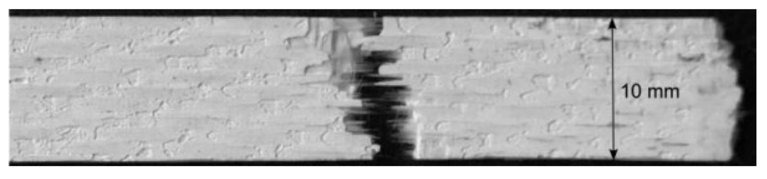
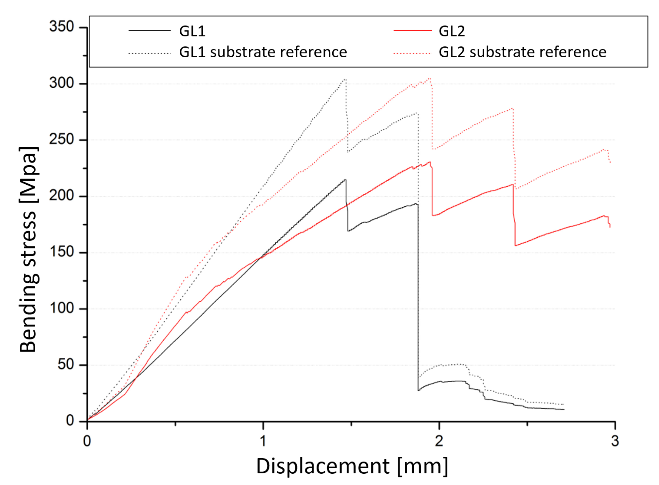
2.1.1. Strength Tests

For the experimental investigation of the mechanical properties of coated and uncoated material samples, destructive material testing methods in the form of 4-point bending tests according to DIN EN 658-3 [11] are used. By means of these tests, the total strength of the CMC can be determined, as a multi-axial stress state is generated. The planes below the neutral fibre experience tensile stress, while the region above is under compressive stress. In addition, the material sample is subjected to interlaminar shear as a result of the transverse force shear resulting from the stress distribution, for which the matrix strength is decisive. Due to this overall consideration and the significantly simpler specimen preparation compared to tensile and purely interlaminar shear tests, bending tests were chosen as the test method. The tests were carried out on a Zwick Z005 testing machine at a test speed of 3 mm/min.
The specimens had a thickness of 1 mm. The ratio of the outer support spacing (60 mm) minus the inner support spacing (20 mm) to specimen thickness was 40 to ensure pure flexural failure as a damage case. For the fabrication of the specimens, four fabric layers were laminated on a mould plate. Due to the weave pattern, the fabric had two different sides. For the samples, identical sides were always laminated on top of each other. The sample plate was then dried at 110 °C, demoulded and fired at 1200 °C for five hours. After the sample plate had cooled in the air, the samples were sawn out with a diamond cutting disc so that the longitudinal fibre direction corresponded to the sample orientation. The samples had a width of 10 mm and a length of around 100 mm. Since the thickness of the specimens varies due to manual fabrication, they were calculated from the mean of four measurements taken with a sliding gauge. The mould side of the specimens was always directed downwards in the bending tests.
In the bending tests, force-displacement curves were measured, from which the course of the bending strength σ was then determined. This is calculated according to the following formula from the outer support distance L, the inner support distance l, the specimen width b, the specimen thickness d and the maximum force F m a x :
σ = 3 F m a x ( L l ) 2 b d 2 .
Since the specimen thickness enters quadratically into the formula for calculating the bending stress, it has a relatively large influence on the result. Unfortunately, due to the surface roughness of the material, the measurement of the specimen thickness is subject to an error, which is reflected accordingly in the final result. Therefore, the investigation should be statistically secured by a sufficiently high number of tests. The application of the aforementioned equation should still be viewed critically, as it is only valid for tough-elastic materials that behave the same under tensile and compressive stress. Since fibre-reinforced composite tensile stresses are mainly absorbed by the fibre and compressive stresses by the matrix alone, the calculation can only be transferred to OCMCs to a limited extent. The results should therefore be viewed with appropriate caution. However, since the primary aim of the investigations is a direct comparison of identically tested samples, this fact does not affect the further discussion.
The bending specimens were tested until failure occurred, which is in the range of the maximum bending moment, i.e., within the inner supports. If there is damage-tolerant material behaviour, the bending stress shows a stepped progression. This is because the failure of the first layer leads to a load drop. Consequently, the force acts on the remaining layers from then on until they also fail. This is in contrast to the quasi-ductile material behaviour, where the specimen breaks as a whole. In the record of the bending stress, the latter presents itself as a single steep load drop. This behaviour is undesirable due to the lack of damage tolerance.

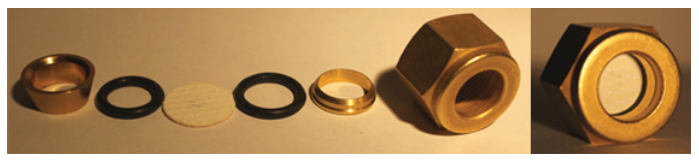
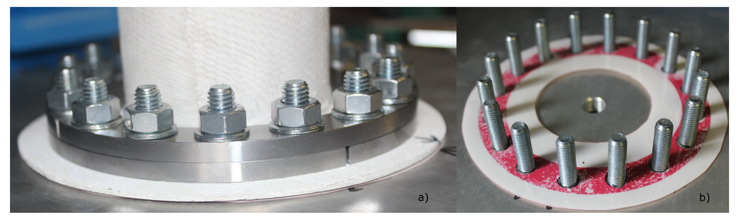
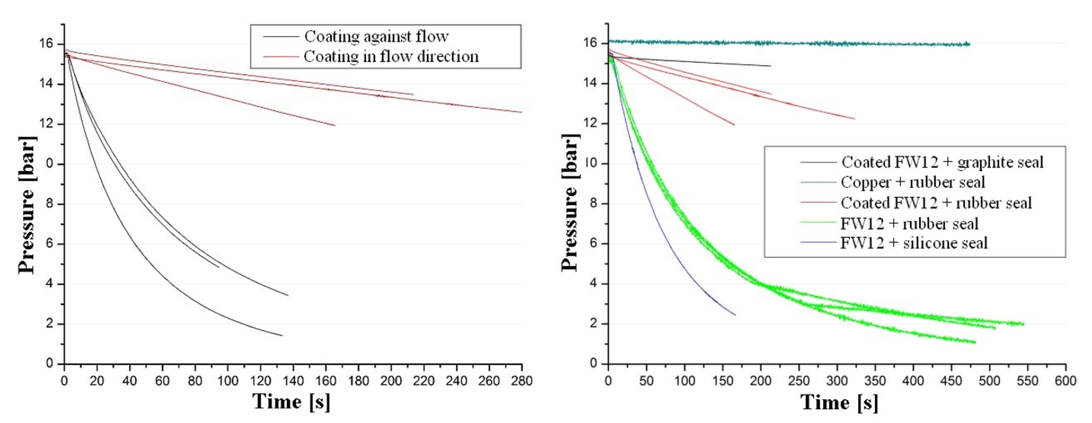
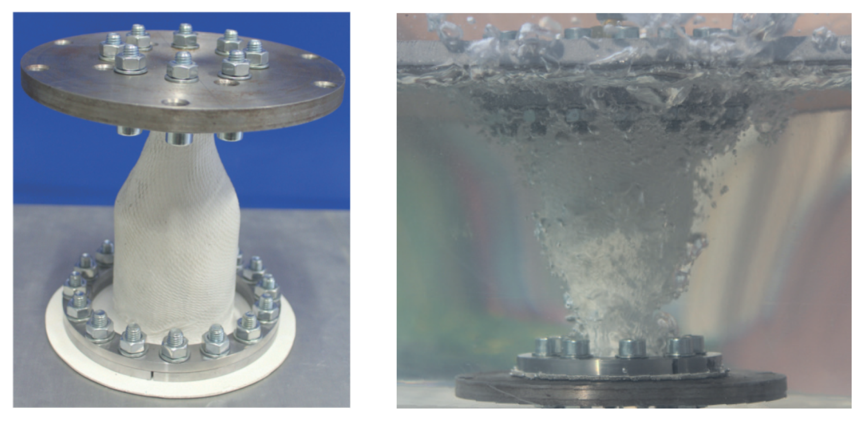
2.1.2. Leakage Tests

In order to evaluate the performance and suitability of the coating, a series of leak tests was carried out in accordance with DIN EN 1779-D1 [12]. The concept of these tests was to measure the pressure drop across the coated and uncoated samples and thereby make a qualitative statement about the influence of the coating. The design of the samples and their integration is shown in Figure 3. Discs with a diameter of 18 mm were milled out of a plate with four fabric layers and then round ground to a final diameter of 17 mm. Since there is a smoother and a rougher mould surface, the specimens were tested in both directions. In addition, samples with three, six and eight fabric layers were made to investigate the effect of sample thickness on permeability. However, all coated samples had a number of layers of four.
The discs were placed in a sample holder together with the seals, as shown in Figure 3. Different types of gaskets were tested for this. The assembly was then integrated into the test bench described below. The tests were carried out in the oxygen section with nitrogen gas at room temperature and an initial pressure of 15 bar. The sample holder was mounted at the end of the oxygen section and the pressure curve was measured. In order to check the test setup and to obtain a reference value, a comparative test was carried out with a gas-tight sample disc made of copper.

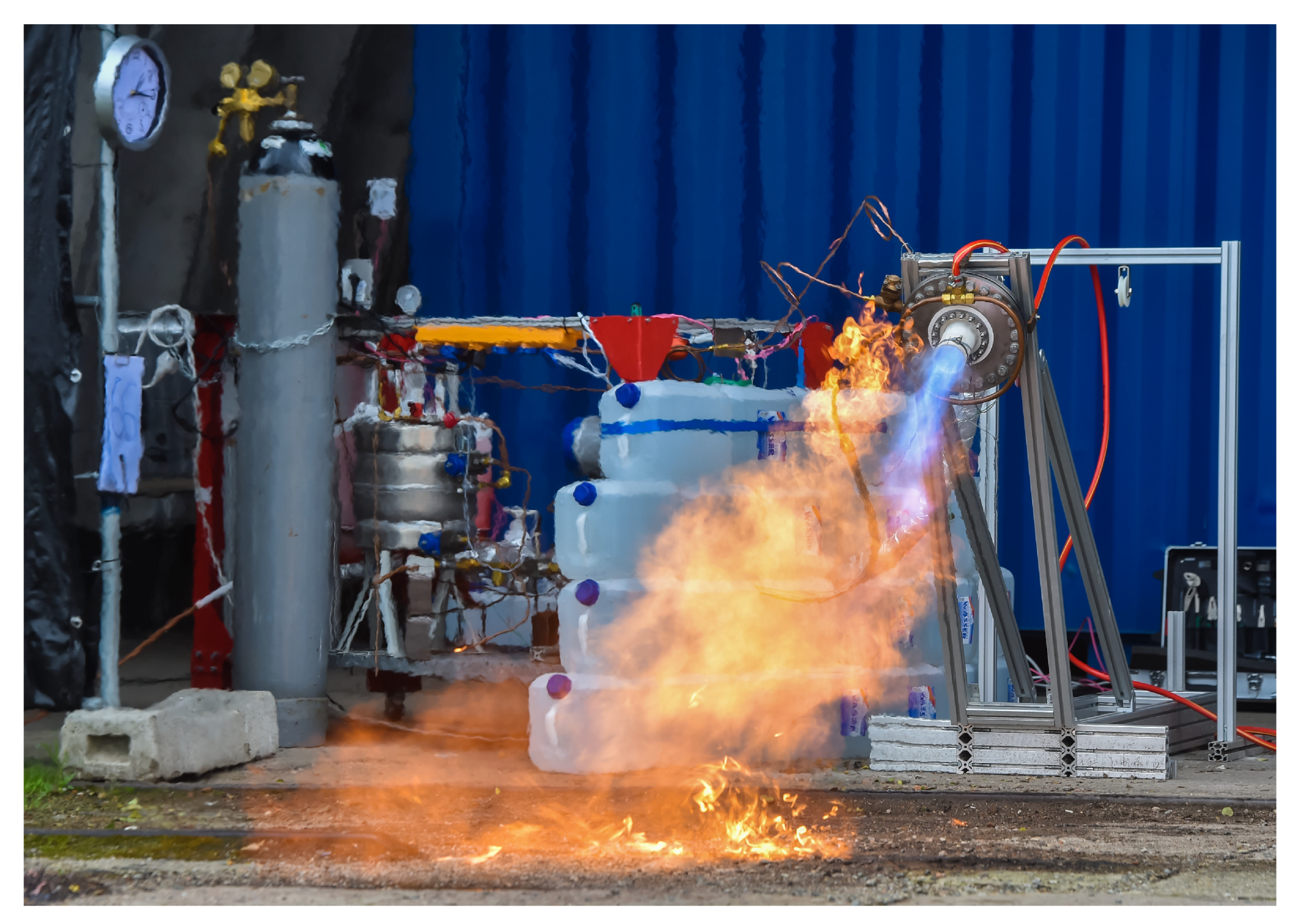
2.1.3. Hot Gas Tests

Of paramount importance in engine applications is the strength that materials exhibit at high temperatures. This is especially true for OCMCs as they have a relatively low thermal conductivity. This results in a greater heat transfer resistance between the combustion gases and the thrust chamber wall, which in turn leads to an increased temperature gradient within the wall. In contrast to metallic thrust chambers, thrust chambers made of OCMC therefore have a lower outer wall temperature and can consequently radiate less thermal energy to the environment. In other words, the radiative cooling of OCMCs works worse than with metallic materials. Since the thermal conductivity cannot be increased significantly, the only way to improve the thermal balance is to increase the emissivity. For increasing the emissivity, a coating can be utilised. Unfortunately, the emissivity of the available coating is not known and cannot be determined easily. It can be assumed, however, that no large increases in emissivity can be achieved since the coating in question is also an oxide ceramic system. One possibility would be to add SiC particles to the coating, but this could not be implemented in the context of the investigations carried out here due to the already very limited availability of the coating.
In situ, the determination of strength is associated with high effort and consequently high costs. The standards DIN EN 1893 [13] and DIN EN 12789 [14] specify procedures for tensile and bending tests on CMCs at elevated temperatures. In principle, these hardly differ in procedure from corresponding tests at room temperature. However, a significantly more complex infrastructure is necessary for their implementation. This includes, among other things, sufficiently large furnaces into which the testing machines can be integrated. Accordingly, the temperatures at which the tests can be carried out are limited to the lowest maximum operating temperature of a component installed in the testing machine.
In order to be able to investigate the high-temperature behaviour of the OCMC FW12 and its coating in advance, experiments were carried out with an oxy-acetylene torch, the flame of which was directed at different distances and angles onto coated and uncoated material samples. The exposure was maintained until failure of the sample, but for a maximum of 20 s. The flame temperature is around 3200 °C in the core, while temperatures between 1200 and 2500 °C occur in the scattered flame. Since most available thermocouples can only be used at temperatures of up to 2000 °C and thermocouples for higher temperature ranges are cost-intensive and prone to oxidation, it was not possible to measure the sample temperature directly. Without contact, the temperature could have been determined with a pyrometer if the emissivity was known. However, such a device was not available for the test, so that only qualitative conclusions can be drawn from the investigations [15].

2.2. Prototype Development

After successive tests in the last subsection underpinned the application potential of OCMCs in rocket engines, this subchapter deals with the development of first prototypes to investigate the behaviour in hot tests and the manufacturing processes. The first part deals with a flame tube that mirrors a cylindrical combustion chamber, but with no nozzle attached. The second part then deals with a more complex prototype that combines the cylindrical combustion chamber part and a conical Laval nozzle. Both prototypes were concerned with the basic investigation of the material, so no coating was applied in either case. Before that, the test rig utilised for these and subsequent investigations is briefly described in the following.

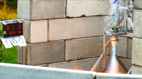
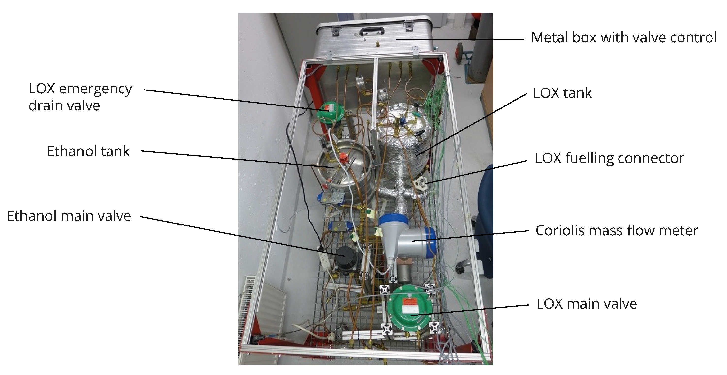
2.2.1. Rocket Engine Test Bench
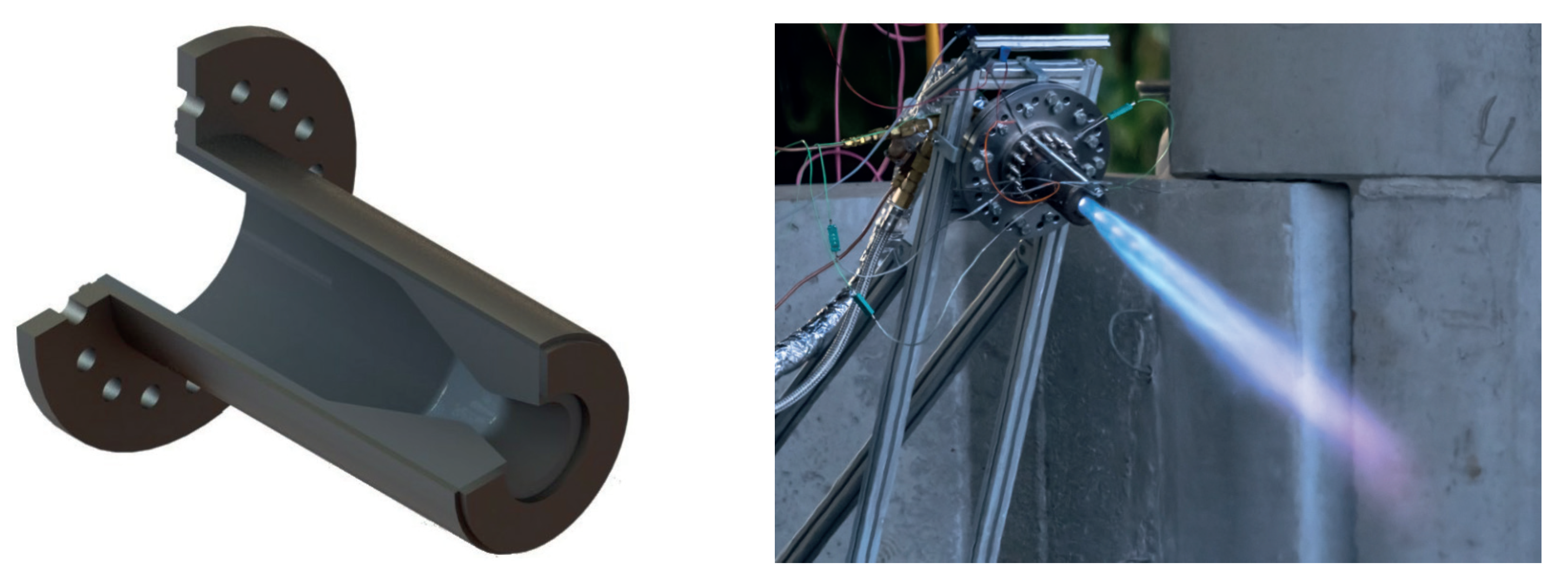
The test rig was built to accommodate verification tests of LRPEs and their components. Here, the propellants used were ethanol and LOX. The test bench, as shown in Figure 4, consists of two collaterally arranged fluid lines, one for each propellant, in a mobile cart. A thrust frame was incorporated for the assembly of thrust chambers. The force sensors in the thrust frame can be varied for thrust range 100 to 3000 N. The thrust chamber was inclined in such a way that no fuel residue can remain in the thrust chamber.
Nitrogen is used to pressurise and convey the propellants from the tanks to the thrust chamber as well as to flush nitrogen into the thrust chamber. The rig additionally houses solenoid control valves, pressure reducers as well as a data acquisition and test bench control system. All the sensor signals are collected in a metallic control box, which acts as an interface between the operator and test stand. The metallic housing forms a barrier among the electrical lines and fluid lines, thereby minimizing the risk of fires and explosion. In the event of a power failure, all valves will be closed automatically.
Measured physical properties include pressures and temperatures in lines and tanks as well as mass flows for both lines to monitor the operation of the test rig. Additional sensors can be applied to the test specimen. The control of the test bench as well as the processing and display of the measured values is carried out via a specifically developed LabVIEW program. The test procedure can be either sequenced automatically or operated manually. The user interface of the program presents the entire states of the flow, piping and instrument flow diagram of the test bench. This gives the operator a direct overview of the status of the system. In order to exclude human errors, the control program has been written in such a way that it automatically intervenes when certain threshold values are exceeded, and resets the test bench to a safe state. In addition, all recorded measured values can be stored in a log file for subsequent evaluation. Finally, a set of cameras were installed for test video recording, redundant monitoring of tank pressures and for overall monitoring of the test field to assure safety.

2.2.2. Flame Tube

The contour of the flame tube describes the cylindrical part of a rocket combustion chamber with 65 mm diameter and 125 mm length. The wall thickness varied between 3.0 and 3.5 mm in the cylindrical part and up to 3.8 mm at the flange. Additionaly, a right-angled flange was attached with which the connection to the injector head was realised. The material from which the flame tube was made is similar to the FW12, but has lower performance characteristics. Since the flame tube does not have to withstand high combustion pressures due to the lack of a nozzle, the decision was made in favour of a less expensive material. In order to investigate the behaviour of the OCMC under the influence of actual combustion gases, the flame tube was mounted on the thrust frame of the test rig described above. Figure 5 shows the flame tube in the test rig operation.

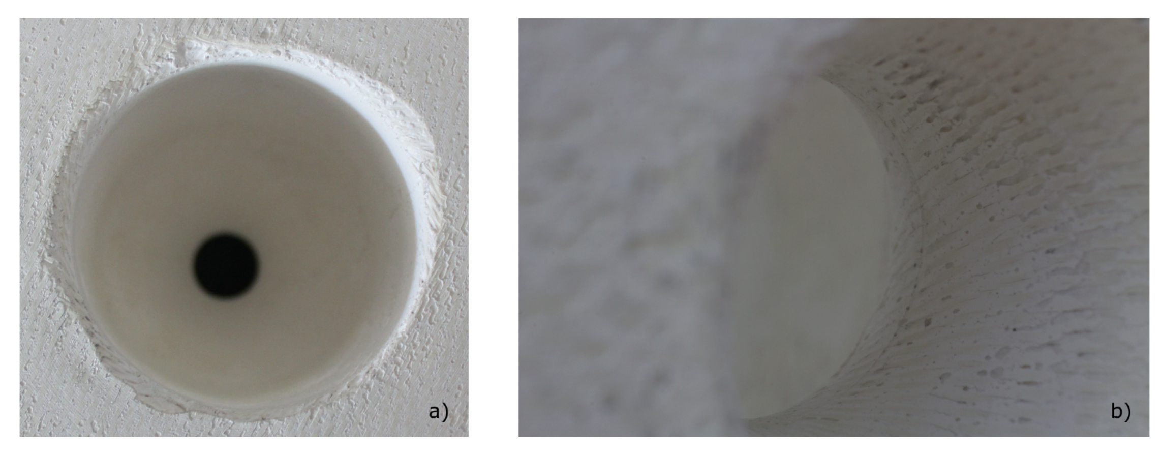
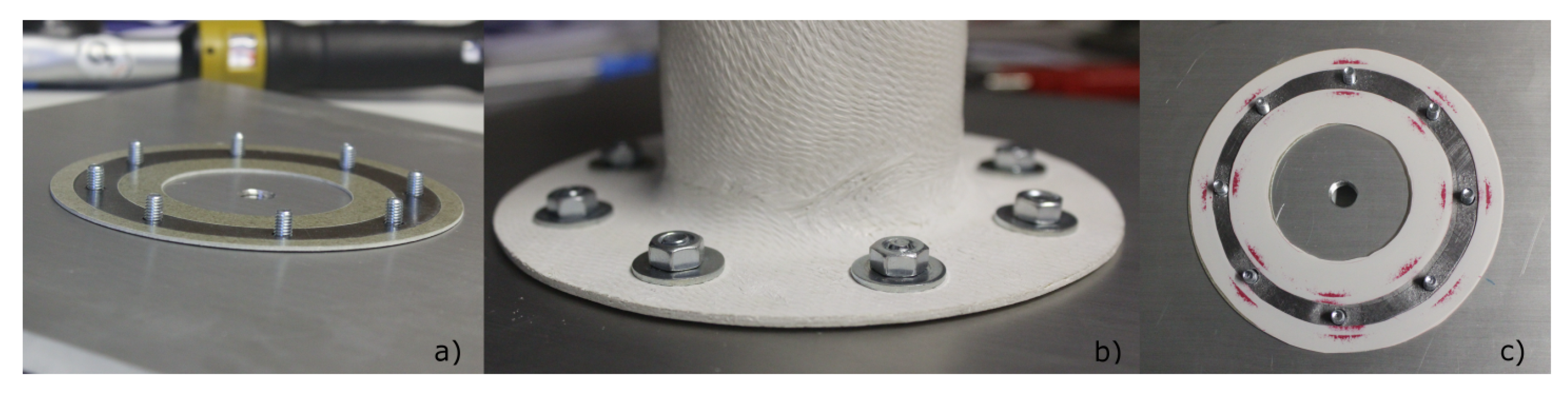
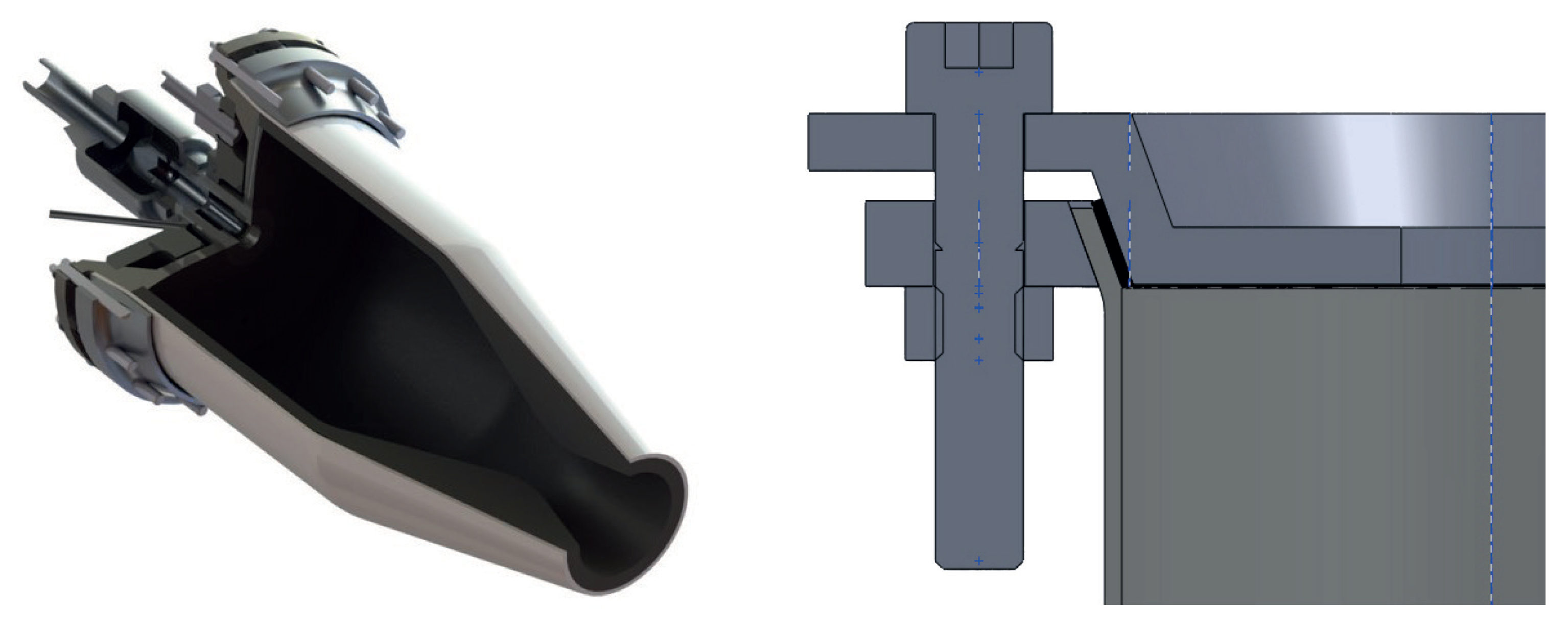
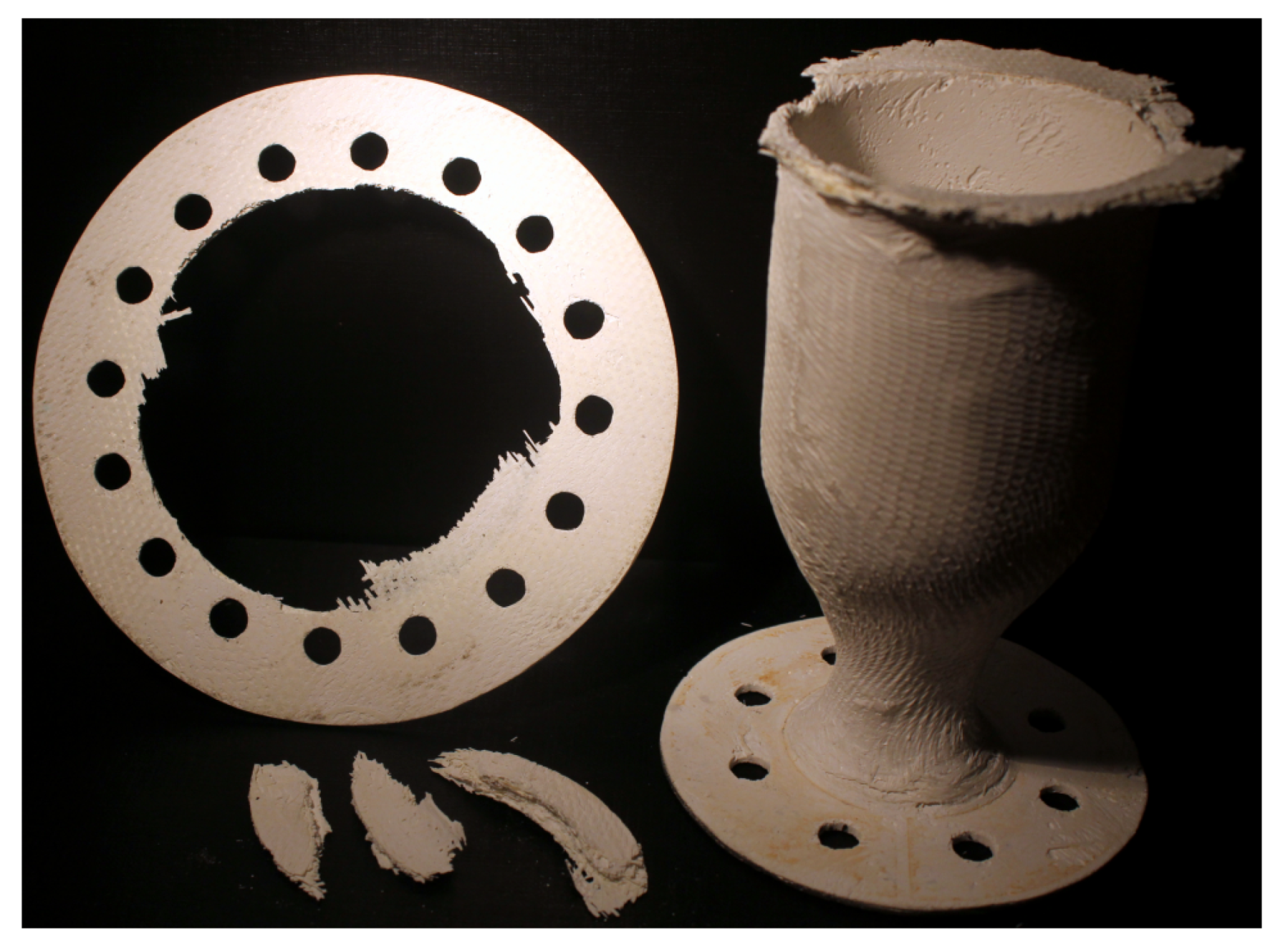
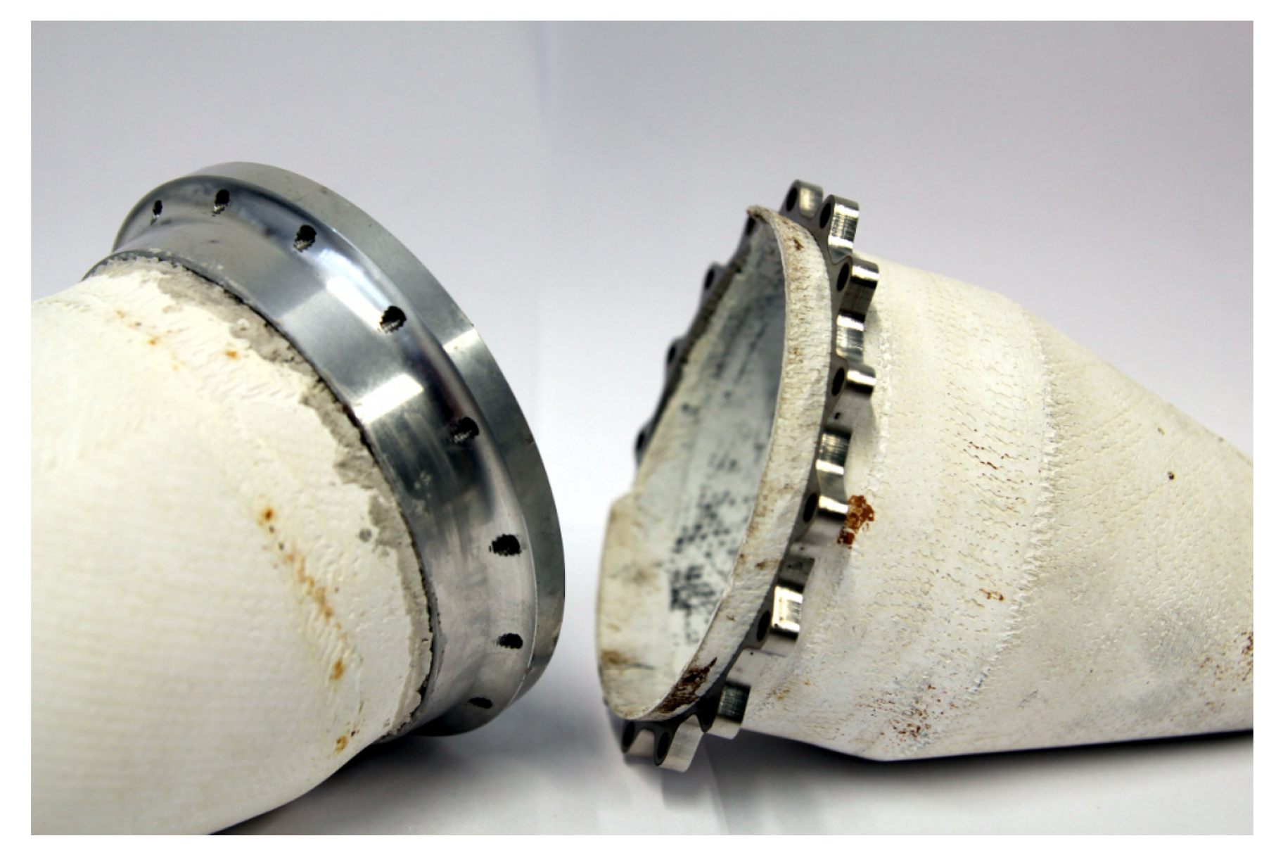
2.2.3. Ceramic Chamber and Nozzle

In addition to the flame tube, a second prototype was developed, which, as can be seen in Figure 6, combined a conical nozzle in one component in addition to the cylindrical combustion chamber part. In addition, there are flanges at the combustion chamber and at the nozzle outlet to enable assembly and sealing of the volume. For this purpose, a mould was first made from SikaBlock® M940 [16] onto which the final component can be laminated. The moulded body shown in Figure 6 has a segmented structure to enable the production of firing chambers of different lengths and non-destructive demoulding. Due to the complex contour, a simple winding of the fabric was not possible. Instead, individual layers had to be applied to the mould. The fabric layers were prepared to slightly overlap the combustion chamber. To map the nozzle neck and the flanges, it was necessary to cut into the fabric. As a result of the additional overlaps created by this, the nozzle neck has a greater wall thickness. Since increased loads are to be expected in this area, the thickening is considered an advantage. In order to achieve high strength, a structure consisting of four layers at angles +45°/0°/90°/−45° was chosen, as shown in Figure 7. The 45° layers can be warped very well and are therefore easier to place on the mould. An additional fabric layer was applied to both sides of the flanges to achieve the straightest and cleanest possible finish. In addition, the six-layer structure provides reinforcement for later assembly.
It can be seen from the manufactured component that the flange areas were difficult to produce. Especially in the bends at the transition from the cylindrical part to the flange, it is difficult to establish a shape fidelity. Although the fabric can be pressed into the corners, it always springs back. This prevents the reproduction of sharp edges, as can be seen in Figure 8 on the left. The desired flatness of the flange surfaces is also a challenge. In particular, the side facing away from the mould has a high degree of roughness. The side facing the mould has a better quality. Nevertheless, both sides have to be surface ground afterwards. A corresponding counter mould could minimise the effort involved. The roundness and surface quality of the inner contour is also in need of optimisation, as the fabric has partially detached from the mould during the lamination process. Here, the first fabric layer should be wrapped with a roving. This process has already been used in the area of the nozzle neck and has produced satisfactory results, as can be seen in Figure 8 on the right.
As discussed above, the sealing surfaces and seals used are of great importance. Since pressure tests up to at least 15 bar internal pressure are to be carried out with the manufactured prototype, the choice and design of the sealing principle are essential for the tests. While metallic thrust chamber components can be tightly welded or soldered together, the connections of ceramics and metal must be designed in a different way so that they seal gas-tight even at high pressures, high temperatures and in oxidising atmospheres. Flanges were provided for the connection of the prototype, which enclose a surface seal that is held in position by the pitch circle. The quality of the sealing surface is highly relevant. Since this faces the mould and was mechanically finished, a relatively high surface quality could be achieved. Nevertheless, the fibrous structure of the material and the presence of bubbles within the matrix are visible to the naked eye.
Such unevenness must be compensated for by a suitable seal. Expanded graphite was chosen as the sealing material for sufficient adaptation. The material used was SF TRD 401 from the company thoenes® [17], which withstands operating temperatures of up to 2500 °C. Since this is pure carbon, the seal must be protected from oxidation. Accordingly, the operating temperatures only apply in the absence of oxygen. Direct contact with liquid oxygen should be excluded due to the high risk of fire. As shown in Figure 9, the graphite was therefore protected by an intermediate layer of mica both on the side facing the combustion chamber and on the side facing the environment. This high-temperature flat gasket material, called Hi-Temp 710, consists of at least 90% phlogopite and maximum 10% silicon and has a maximum application temperature of 1100 °C [18].
In order for the graphite to compensate for the unevenness of the ceramic surface, it must be pressed sufficiently. A special indicator foil from Fuji was used to determine the contact pressure. This is placed parallel to the seal used between the components to be joined and changes colour to a greater or lesser extent depending on the contact pressure. The foil used here can indicate pressures between 10 and 50 MPa by changing colour from white to light to dark red [19]. In addition to the contact pressure, the discolouration also depends on the ambient temperature and humidity. By comparison with a comparative scale, the pressure of the surface pressure can be determined locally. Figure 9 shows that initial tests in which the flange connection was realised using eight M6 bolts with associated washers produced unsatisfactory results. Although the surface pressure in the area of the screw heads and washers can be considered sufficient, the contact pressure could not be maintained between these areas because the stiffness of the 2 mm thick ceramic is not high enough.
To improve the sealing effect, various changes were made. The M6 bolts were replaced by M8 bolts of strength class 8.8, which increased the tightening torque up to 25 Nm. In addition, the number of bolt connections in the bolt circle was doubled to reduce the distance to be bridged between the bolts. Finally, in addition to the washers, two shims, each made of 5 mm thick steel, were used to distribute the pressure more evenly. The width of these washers corresponds to the width of the graphite gasket. The mica used as an oxidation barrier is 0.3 mm shallower, so that the graphite can be sufficiently compressed before it closes with the mica. Essentially, this is why two rings were used, because the underlay ring does not fit over the flange located at the nozzle end and thus has to be made in two parts. Therefore, a second underlay ring, offset by 90°, was added. This design can be seen in Figure 10.
The changes obviously resist a lightweight construction, but have proven to be expedient for the intended tests. It can be seen from the surrounding red ring in Figure 10 that a largely uniform surface pressure could be achieved. The fibrous structure of the ceramic surface causes the inhomogeneities that can be seen in the impression. However, as long as these do not form continuous channels bridging the seal, they can be regarded as unproblematic. In addition, it can be assumed that the indicator foil used prevented optimal matching of the graphite. This is confirmed by Figure 11, which shows a graphite gasket pressed without indicator foil. The fibre structure of the OCMC surface is homogeneously reflected in the imprint on the gasket surface.
In order to test the prototype for pressure resistance at room temperature, both openings were closed with metal plates. A steel plate was used on the nozzle side. On the combustion chamber side, an aluminium plate was used, which had a connection for the supply of nitrogen gas. The latter was taken from a commercially available compressed gas cylinder and expanded via a pressure reducer. The pressure was to be gradually increased from 5 to 20 bar in steps of 5 bar. To protect against flying splinters and to facilitate the detection of leaks, all pressure tests were carried out in accordance with test method C3 to DIN EN 1779 [12] under water in a transparent container.

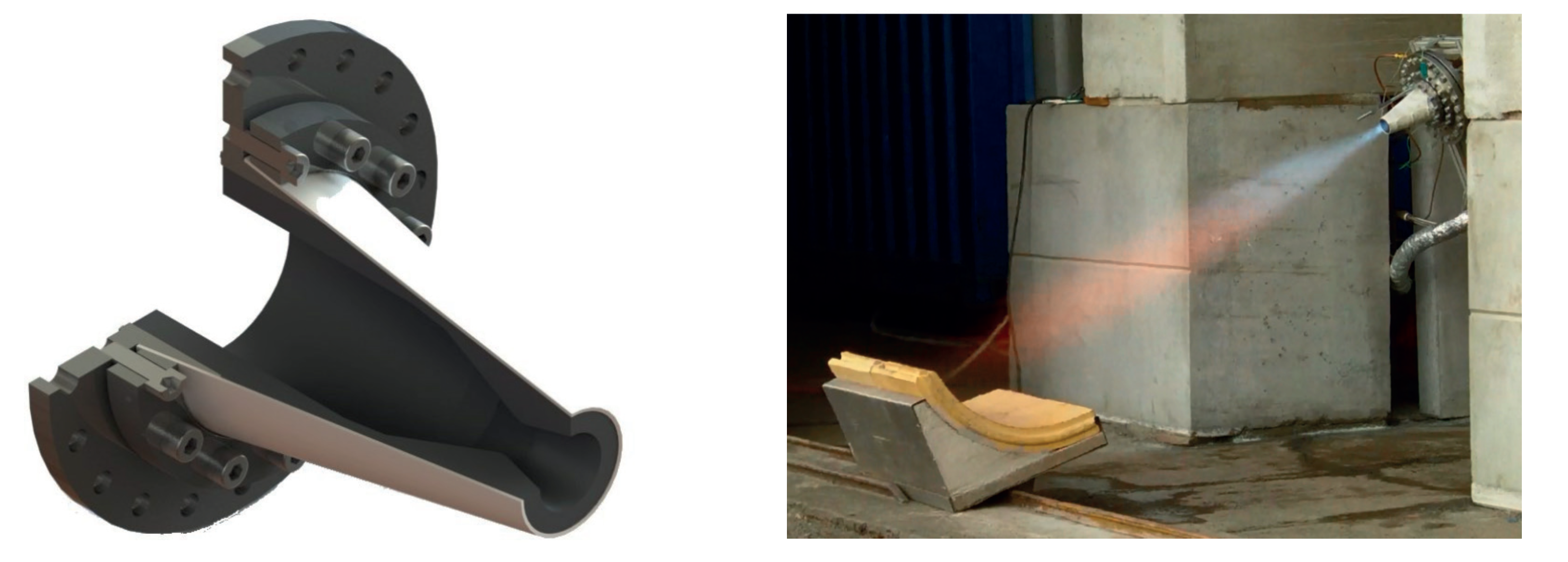
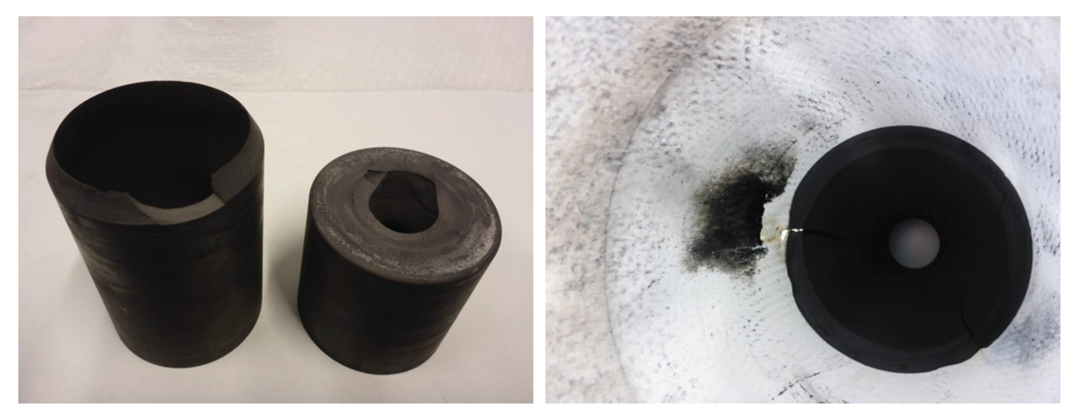
2.2.4. Ceramic Chamber with Graphite Inlay

Based on the experience gained with regard to the production of complex and exact geometries and their connection to the injector head, it was decided to continue with an alternative design concept for the time being. As can be seen in Figure 12, the contour of the combustion chamber and the adjoining nozzle is not formed by the OCMC, but by an inlay made of graphite. The OCMC serves as an outer shell which absorbs the mechanical loads. This modular design has the advantage that the flow contour can be produced more precisely and with significantly less effort. In addition, the surface quality and porosity of the OCMC play only a subordinate role, since the graphite is impermeable to gas. Of course, this design does not exhaust the application potential of the OCMC discussed at the beginning of this chapter. But on the other hand, further knowledge can be gained from the connection with the injector head and its testing in operation, which can be of high value for future developments.
The connection between OCMC and the metal injector head was revised for this prototype. A flange connection with washers was still used. However, instead of making it perpendicular to the main axis, a conical flange was used, which has a self-centring effect. In addition, the spacer ring was now used as a clamping ring. This means that the bolt circle no longer has to be elaborately worked into the OCMC. The basic principle of this connection is illustrated in Figure 12. It has the advantage of significantly smaller angular changes, which benefits both the production and the strength as a result of the fibre path. On the other hand, there is the disadvantage of a conical sealing surface, which cannot be equipped with a flat seal. For this reason, the sealing was realised with a ceramic adhesive. Consequently, it cannot be guaranteed that the combustion chamber can be dismantled without damage. Several hot tests were carried out, in which the performance and thus also the stresses were increased from test to test.

3. Results

3.1. Strength Test Results

Since the glaze is an unprotected test product and is only available to a very limited extent, unfortunately only two coated test samples could be created. Statistically reliable results could not be obtained from this. However, initial statements can already be made on the basis of the measurement curves recorded in Figure 13. In sample GL1, the glaze was aligned upwards, in sample GL2 it pointed downwards. In the stress increase of the latter, a non-linear and thus elastic area is shown. The reason for this behaviour is that the sample is not straight, but bended. This bending re-sults from the fact that the coating was applied only on one side, which results in an asym-metrical force that the sample cannot withstand and thus leads to its bend. However, the resulting bend is evidence for a sufficient adhesion between the coating and the substrate. If the adhesion would be insufficient, the force could not be transferred to the sample and no bending would occur. The distortion could be avoided by applying the coating on both sides. Although the final stress drop in sample GL1 occurs earlier, it is not possible to conclude that the results are directional due to the small number of samples.
In addition, it can be seen in Figure 13 that the bending stress was calculated for two different reference cross-sections. In the first case, the total thickness of substrate and glaze was used, in the second case only the thickness of the substrate material was used for the calculation. The latter value is closer to reality, as the coating, which has a thickness of around 200 µm, makes at best a small contribution to the overall strength. Accordingly, maximum bending stresses of about 300 MPa result. These are at the lower limit of the bending strength of FW12, which is about 300 and 400 MPa. The stepped progression of both bending stress curves testifies to a preservation of the damage tolerance of the substrate material.
Figure 14 confirms that the coating is matched to the OCMC FW12 such that the weak matrix concept is not affected. It is true that the glass-like coating breaks brittly and consequently has smooth fracture edges. However, the crack does not continue unhindered, but follows the previously discussed propagation behaviour. Thus, the damage tolerance based on fibre pull-out is maintained even after coating. However, further investigations should be carried out. In particular, it should be investigated to what extent the lack of damage tolerance leads to the appearance of cracks in the glaze when the component is subjected to thermal shocks and stresses, as this would eliminate the gas tightness [1,20,21].

3.2. Leakage Test Results

The left diagram in Figure 15 shows the good sealing performance of the copper sample. In contrast to this, the uncoated OCMC samples show a rapid pressure loss. Considering the usual burn times of rocket engines, the initial slope of the pressure curve is of particular interest. With decreasing pressure, the leakage rate also decreases accordingly, which leads to a decreasing gradient. Furthermore, it can be concluded from the diagram that the direction in which the material discs were integrated into the sample holder has no influence on the results. The right diagram in Figure 15 shows the time-dependent pressure behaviour of samples with different thicknesses. It can be seen that a larger number of layers and thus higher sample thickness leads to a slower pressure loss.
The left diagram in Figure 16 shows the pressure curves for the coated samples. All samples were coated on one side only, while the other side was left unchanged. For this reason, the samples were also examined in both possible installation directions. In contrast to the left diagram in Figure 15, the coated samples show a clear directional dependence. This is due to the sealing of the material discs in the specimen holder. If the rough, uncoated side is pressed against the seal, the observable behaviour shows a steep pressure drop similar to uncoated samples. If, on the other hand, the coated surface forms the interface to the seal, a significantly slower pressure drop can be observed. This shows that the coating creates a significantly better sealing surface. Nevertheless, a noticeable pressure drop also occurs here, which can be attributed either to the integration of the specimen or to a defective coating. To rule out the latter, the sealing system was varied. The results of this investigation are shown in the diagram on the right in Figure 16. They lead to the conclusion that the coating of the OCMC FW12 works best with a gasket made of graphite. The result obtained with this combination is close to the reference behaviour of the copper sample. In summary, the main challenge in the application of OCMC in rocket engines, its inherent and characteristic permeability, can be overcome with the application of a specially tailored glaze. This significantly reduces the difficulties of the material application to the sealing problem. Here it was shown that this can be satisfactorily solved with a flexible graphite seal.

3.3. Hot Gas Test Results

The oxy-acetylene torch was powerful enough to locally melt and disintegrate a 10 mm wide and 1 mm thick sample within about 3 s at direct exposure. At greater distances between the burner and the sample, the scattered flame causes the samples to soften and bend under their own weight. Monolithic areas form under this partial melting, which results in a loss of any damage tolerance, so that the samples exhibit brittle fracture behaviour after cooling. With increasing distance, the heat input decreased so that the samples could survive test durations of 20 s without noticeable damage.
The basic behaviour is shown in Figure 17. After 20 s, local melting occurred on the surface of the longitudinally flowed material sample, which can be seen in Figure 18. The melting mainly affects fibre bundles lying on the surface that were exposed to the direct incident flow. Downstream, there was also a brownish discolouration of the surface. On closer inspection, this area shows small cracks resulting from thermomechanical stresses. In principle, local melting also leads to a loss of damage tolerance.
Compared to the uncoated material samples, the coated samples exhibit an increased service life of around 6 s when exposed to direct flame. Here, a melting and foaming of the glaze can be seen, which dissipates energy and briefly protects the underlying substrate. This thermal protection effect of the glaze becomes even more evident at a greater distance between the sample and the burner. In Figure 19, it can be seen that although the glaze foams up after a certain time, the substrate remains intact. Although this is a positive effect, the foaming of the glaze causes a loss of the sealing effect. Future tests should investigate whether a double-sided coating can provide thermal protection and sealing at the same time. However, it can be assumed that the high flow speeds in the nozzle area lead to rapid removal of the glaze.

3.4. Flame Tube Test Results

A total of five cycles of varying lengths were performed. Exemplarily, the sequence of the last test is shown in Figure 20. Before the combustion, a chill down procedure with pure LOX flow was conducted. This is displayed in the data in the time window between approx. 50 s and 140 s. The actual combustion took place in the time window of approx. 215 s to 245 s with an active LOX and ethanol flow. All five tests have been conducted in a similar way with slightly different settings on the propellant pressurization in order to adapt the mass flows.
The longest test run involved over 60 s stable operation. A longer test could not be performed due to the limited volume of the fuel reservoirs. The flame tube was neither dismantled nor replaced between the tests. It survived all tests without visible damage. Although no temperature measurement could be carried out due to the poor integrability of thermocouples, conclusions can be drawn from the measurement data summarised in Table 3 and the visual appraisal of the experimental model. Figure 21 shows the flame tube mounted over the flange connection before and after the tests. The metallic deposits that can be seen in the picture taken after the tests originate from the sparkler that was used as an igniter. The fact that the spark plug’s steel rod melted during the test indicates hot gas temperatures of at least 1500 °C. Furthermore, a colour change of the inner material surface is clearly visible. This results from the deposition of soot, which is produced during the combustion process due to the fuel-rich propellant mixture. A colour change can also be seen on the outside, although it is much less pronounced. The porosity of the material may be responsible for this. Another explanation would be that the material has changed. A final assessment cannot be made without detailed examinations. It should be noted that the side of the injector head facing the combustion showed the first tarnishing after the hot tests, which did not yet occur with open burns. This means that there was a build-up of heat near the injector and shows that the flame tube had a throttling effect on the combustion gases.
With the presented tests, it can be stated, that the OCMC flame tube survived the conditions imposed by a fuel-rich combustion of LOX and ethanol at the required mixture ratio of 1 : 1 ± 0.25 also in steady state. But this demonstration is only a step towards a combustion chamber made of OCMC, since it lacks of a convergent nozzle part, which causes higher pressures in the combustion chamber and therefore sinificantly higher heat loads on the material.

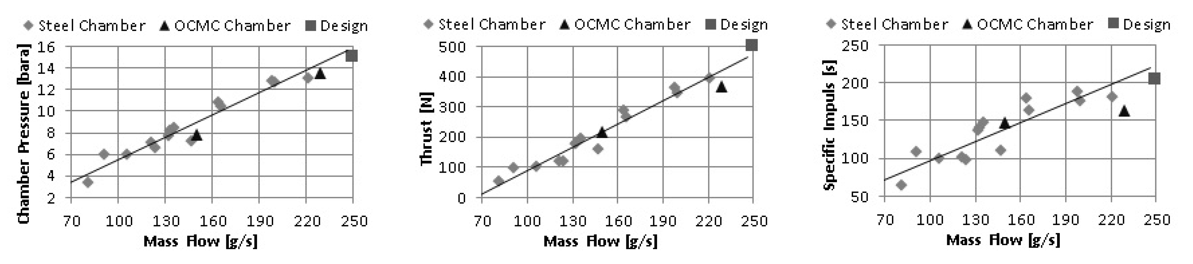
3.5. Ceramic Chamber and Nozzle Results

Leakage was expected due to the porosity of the OCMC and the tests carried out in this regard in the previous subsection. During the tests, it could be seen that gas bubbles occasionally escaped. However, far greater leaks resulted from the closure of the nozzle outlet. Here, the gas escaped between the seal and ultimately from the screw holes. This is visible in Figure 22 on the right.
Despite the clear leakage, the gradual increase of the pressure level was continued to test whether the prototype could withstand the pressure loads. During the test with a target pressure of 15 bar, large-scale material failure occurred early on. As can be seen in Figure 23, the large flange on the side of the combustion chamber was destroyed. The fracture edge is located in the area of the inner edge of the shim rings and graphite gasket. Since the gas pressure is isostatic, it counteracts the flange connection up to the bottom ring. This situation is illustrated in Figure 24. It is possible that the pre-tensioning force of the washers caused pre-damage and a notch effect, which led to the crack.
It was then investigated whether the damage was due to shear failure. For this purpose, the circumference of the crack was determined at the inner diameter of the shim rings of 95 mm. Since the pressure at which the failure occurred could not be determined exactly due to the fact that the measured values had not yet been recorded, the target pressure of 15 bar was used. This results in a force of 10.63 kN over the area of the flange of 7088 mm 2 reaching to the inner edge of the shim rings, which is absorbed by the CMC. Its cross-sectional area is calculated to be 656 mm 2 for a measured thickness of 2.2 mm. The ratio of force to cross-sectional area results in a shear stress of about 16 MPa, which is well below the shear strengths for FW12 of 60 to 90 MPa found in the literature [22,23].
As a result of the tight clamping of the material at a tightening torque of 25 Nm with 16 bolts, preliminary damage cannot be ruled out. As already mentioned, the component had a thickness of 2.2 mm in the area of the flange, although the six-layer structure with a fabric thickness of 0.25 mm should result in a material thickness of 1.5 mm. The resulting lower fibre-to-matrix ratio, or the lower fibre volume content, leads to a lower strength of the composite. This explains the damage. In order to avoid the shear stress, the gasket or mica should reach up to the combustion chamber. An increase in the contact surface of the shim rings would not be effective, as this would reduce the contact pressure, which would mean that a sufficient sealing effect could no longer be guaranteed.
The destruction of the prototype had another advantage in addition to the knowledge gained about the application of the material. Since, as can be seen in Figure 23, smaller parts were torn off in the area of the bend between the cylindrical combustion chamber and the flange, the cross-section of the bend could be analysed in order to draw conclusions about the quality of the manufacturing. Although the crack leading to failure occurred due to the shear effect at the level of the inner edge of the shim rings, weak points in the form of low fibre volume fractions can also be identified in the bend. As can be seen in Figure 25, macropores form between the individual layers during production due to the already discussed poor pressing of the fabric layers into the mould edge. Due to shrinkage processes during drying and incomplete infiltration, only partial matrix accumulation occurs in these macropores. It can therefore be seen that the production of more complex contours and their integration into engine assemblies represent major challenges in the application of OCMCs.

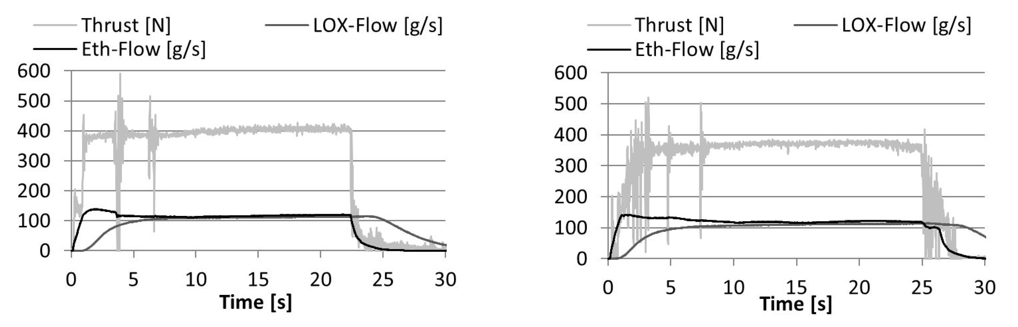
3.6. Ceramic Chamber with Graphite Inlay Test Results

Analogous to the ceramic chamber concept, a comparative engine with a steel casing was developed in parallel. This can be seen in a sectional view and in operation in Figure 26. Figure 27 shows the engine with the casing made of OCMC for comparison. With the steel combustion chamber, 23 test runs were successfully carried out. However, cracks appeared in the graphite inlay, which can be seen in the Figure 28 on the left. Yet the inlay was not destroyed. In fact, it remained intact to the extent that no significant drop in performance could be detected. It can be assumed that these cracks were caused by shocks, as the graphite is a very brittle material and thus susceptible to water hammer. These can be avoided by adjusting the start-up procedure of the engine. Alternatively, fibre-reinforced graphite could be used to withstand the stresses.
Since the same graphite material was used in the OCMC variant of the engine, the test procedure was adapted to minimise the risk of cracks occurring. Nevertheless, cracks in the graphite also occurred here, both in the cylindrical part of the inlay and in the nozzle. From this, it can already be concluded that this graphite is not suitable for such applications. In contrast to the steel casing, the cracks in the graphite inlay in the engine with the casing made of OCMC resulted in damage to the OCMC itself. The local fracture, which can be seen in Figure 28 on the right, results from a local overload occurring as a result of the graphite crack. On the positive side, the damage remained localised and neither the inlay nor the OCMC housing was destroyed. The damage to the OCMC material is thus entirely due to the unsuitability of the graphite material used for the inlay.
The application of the OCMC, on the other hand, is to be judged positively and shows comparable test results to the steel engine. Figure 29 compares the measured values obtained in representative tests graphically. An explicit representation including additionally calculated performance characteristics can be found in Table 4 and shows similar values for both engine types. The graphical representation of the combustion chamber pressure, the thrust and the specific impulse as a function of the fuel mass flow in Figure 30 underpins this. It can be concluded that the OCMC does not have any negative effects in this application, but only the advantage of weight saving. Nevertheless, given the limited number of tests conducted so far, this result for the applicability and suitability of the combustion chamber design is still preliminary and further tests are required to scrutinise the results.
Building on these tests, further engine prototypes were developed using the same design approach. However, a more efficient graphite material was used. In addition, the inlay made of this material was henceforth manufactured in one piece. As a result, the occurrence of cracks was largely eliminated. After modifications to the injector head, which are not discussed in detail in this paper due to their lack of relevance, but which were described by Sieder et al. [24], another test campaign was carried out. As can be seen in Table 5, the engine performance was again successively brought closer to the design level. During test number 131, the OCMC combustor separated from the injector head after just 17 s and hit the ground, splintering off parts of the OCMC envelope. The damage can be seen in Figure 31. Meanwhile, the shim ring used to clamp the OCMC remained connected to the injector head via the flange gland. This means that the OCMC housing slipped out of the flange connection under the combustion chamber pressure. From this, it was concluded that the clamping ring must have already bulged when the screws were tightened and possibly further loosened during operation. For further prototypes, the clamping ring was reinforced as shown in Figure 31, which successfully prevented further damage. An alternative solution would be to increase the angle of the conical connection and thus prevent the housing from slipping out. Although this could potentially save mass, it has already been discussed that stronger deflections are not desirable. As can be seen in Table 5, after implementing the design changes, further tests could be successfully carried out even at increased combustion chamber pressures.

4. Discussion

After the investigations into the application of OCMCs in LPREs have been presented in the previous sections, this section summarises the main conclusions that can be drawn from this development. Based on the knowledge gained, the use of OCMC in LPREs is then discussed. A derivation of future research work that would be necessary to enable a profitable use of the investigated material concludes this section.
The application-oriented material investigations carried out and the development and testing of various prototypes have shown that the use of OCMC in engines has potential advantages over other materials. Particularly worth mentioning here are the lightweight construction potential compared to metals and the oxidation resistance, which sets it apart from carbide CMCs. The remarkable damage tolerance and thermal shock resistance are also interesting material properties for engine applications. However, due to the material structure and the weak matrix concept discussed, these are accompanied by porosity, which makes the material permeable to gas.
In the tests carried out, it was fundamentally demonstrated that gas-tightness can be produced by applying a suitable coating while retaining the strength properties of the composite. Thus, the material can be permeable or impermeable with appropriate post-treatment. This opens up interesting application possibilities, especially in connection with transpiration cooling. Since the coating can also be partially applied, individual areas can be selectively cooled and the effective cooling mass flow can be adjusted.
The applied coating also has the advantage of creating a significantly smoother surface. This not only results in lower flow losses when used appropriately, but also in better sealing surfaces. The latter aspect is of particular relevance, since the sealing of joints between OCMC and metal has been very challenging, also due to the surface quality of the OCMC, and so far could only be solved by an additional bonding of both components. Thus, it must be concluded that the OCMC application, which requires a connection with metallic engine components, is currently not yet satisfactory, since a high effort and additional mass are required for a sophisticated connection.
Furthermore, manual production, which is ultimately also the origin of the sealing problem, represents a high hurdle in the application of OCMCs. Since production cannot yet be automated, high manufacturing costs, insufficient reproducibility and dimensional accuracy that could be improved are unavoidable. It has been shown that in certain cases OCMCs can be used as a substitute for metallic materials and can save mass. However, the higher manufacturing effort and, above all, the material-specific design of the engine must be taken into account in any case.
From the findings obtained, some conclusions can be drawn on the applicability of OCMCs in LPREs. In general, it must be noted that, due to the manufacturing processes, complex geometries are difficult to implement. Accordingly, OCMC could only be used for relatively simple contours, or the design would have to be adapted to the material and production. One starting point is to use OCMC for the outer combustion chamber wall. In particular, if it is possible to implement a double wall, whereby the inner wall is left permeable and the outer wall is provided with a coating, so that transpiration cooling can be applied. However, it seems difficult to manufacture this double wall with sufficient precision. This is imperative because a discontinuous width of the gap would lead to inhomogeneous loads. Thus, ways would have to be found to insert spacers and to finally connect the two walls. The latter is a particularly critical point, as the termination of the outer wall is at the height of the heavily loaded narrowest cross-section of the nozzle.
Based on the investigations carried out, further developments have already been initiated. The knowledge gained from the destruction of the first prototype of a combustion chamber/nozzle unit made of OCMC is being used to develop an optimised model. A design draft for such a lightweight thrust chamber is shown in Figure 32. Of particular interest is the comparison of the operation of an uncoated and a coated chamber, especially with regard to the realisable combustion chamber pressure and the associated engine performance. For this purpose, a measurement of the combustion chamber pressure would be essential. So far, this can only be realised by means of a feed-through inside the injector head, as it is difficult to insert capillaries into the OCMC. It would be obvious to solder the metallic capillaries into the ceramic. Appropriate solders and soldering processes already exist for carbide CMCs. The soldering of metals and OCMCs, on the other hand, is still little researched. These compounds are not only of interest for space engines, but also for numerous industrial applications, for example in plant construction.
Of further interest is to develop processes for the production of OCMC with specifically adjusted porosity. This would allow a better understanding of the interaction between residual porosity and other material properties and thus optimise the coolability and strength of the material. A central component of the research is the measurement of flow resistances and associated pressure losses. Another research approach lies in optimising the manufacturing process. There is a high potential for innovation in the construction of the moulds and the targeted use of counter-moulds. With these investigations, a better assessment could be made of the extent to which the use of OCMCs in LPREs is competitive with other materials.

Author Contributions

Conceptualization, C.B., F.W. and J.S.-K.; formal analysis, F.W.; methodology, F.W.; validation, C.B., F.W. and J.S.-K.; investigation, C.B., F.W. and J.S.-K.; data curation, F.W. and J.S.-K.; writing—original draft preparation, C.B. and F.W.; writing—review and editing, C.B.; visualization, F.W.; supervision, C.B.; project administration, C.B.; funding acquisition, C.B. All authors have read and agreed to the published version of the manuscript.

Funding

This research was funded by Federal Ministry for Economic Affairs and Energy (BMWi) grant number 50RL1256.

Acknowledgments

We are grateful for the support from Walter E.C. Pritzkow Spezialkeramik and would also like to thank all students that engaged in this project.

Conflicts of Interest

The authors declare no conflict of interest. The funders had no role in the design of the study; in the collection, analyses, or interpretation of data; in the writing of the manuscript; or in the decision to publish the results.

Abbreviations

The following abbreviations are used in this manuscript:
BMWiFederal Ministry for Economic Affairs and Energy
CFRPCarbon-Fibre Reinforced Plastic
CMCCeramic Matrix Composite
DLRGerman Space Agency
EBCEnvironmental Barrier Coating
LOXLiquid Oxygen
LPRELiquid-Propellant Rocket Engine
MDPIMultidisciplinary Digital Publishing Institute
OCMCOxide-oxide Ceramic Matrix Composite
TBCThermal Barrier Coating
YSZYttrium-stabilised Zirconia

References

  1. Krenkel, W. Ceramic Matrix Composites; WILEY-VCH Verlag GmbH & Co. KGaA: Weinheim, Germany, 2008. [Google Scholar] [CrossRef]
  2. Boeing. FAA Continuous Lower Energy, Emissions and Noise (CLEEN) Technologies—Boeing Program Overview. In Proceedings of the CLEEN Consortium Public Session, Federal Aviation Administration, Atlanta, GA, USA, 19 November 2014. [Google Scholar]
  3. Pritzkow, W.E.C.; Wehner, F.; Koch, D. Oxide Fiber Reinforced Oxide Ceramic Matrix Composite—An Alternative to Metallic Alloys at High Temperature; Elsevier: Amsterdam, The Netherlands, 2022; Volume 1, pp. 425–441. [Google Scholar]
  4. Schmidt, S.; Beyer, S.; Knabe, H.; Immich, H.; Meistring, R.; Gessler, A. Advanced ceramic matrix composite materials for current and future propulsion technology applications. Acta Astronaut. 2004, 55, 409–420. [Google Scholar] [CrossRef]
  5. Boeing. FAA Coninuous Lower Energy, Emissions and Noise (CLEEN) Technologies—Boeing Program Overview (Presentation). In Proceedings of the CLEEN Consortium Public Session Federal Aviation Administration, Atlanta, GA, USA, 19 November 2014. [Google Scholar]
  6. Göring, J.; Hackemann, S.; Kanka, B. WHIPOX: Ein faserverstärkter keramischer Werkstoff für Hochtemperatur-Langzeitanwendungen. Mater. Werkst. 2007, 38, 766–772. [Google Scholar] [CrossRef]
  7. Ortelt, M.; Hald, H.; Müller, I. Status and future Perspectives of the CMC Rocket Thrust Chamber Development at DLR. In Proceedings of the 65th International Astronautical Congress, Toronto, ON, Canada, 29 September–3 October 2014. [Google Scholar]
  8. Ortelt, M.; Elsässer, H.; Herbertz, A.; Müller, I.; Hald, H. Structural Investigations on Cryogenically Operated and Transpiration Cooled Fiber Reinforced Rocket Thrust Chambers. In Proceedings of the 48th AIAA/ASME/SAE/ASEE Joint Propulsion Conference, Atlanta, GA, USA, 30 July–1 August 2012. [Google Scholar]
  9. Rüdinger, A.; Pritzkow, W. Die Entwicklung oxidkeramischer Faserverbundwerkstoffe am Fraunhofer ISC/Zentrum HTL in Zusammenarbeit mit W.E.C. Pritzkow Spezialkeramik. Keram. Z. 2013, 3, 166–169. [Google Scholar]
  10. Levi, C.G.; Zok, F.W.; Yang, J.Y.; Mattoni, M.; Löfwander, J.P.A. Microstructural Design of Stable Porous Matrices for All-Oxide Ceramic Composites. Ztg. Met. 1999, 90, 1037–1047. [Google Scholar]
  11. Deutsches Institut für Normung e. V. DIN EN 658-3; Hochleistungskeramik—Mechanische Eigenschaften von keramischen Verbundwerkstoffen bei Raumtemperatur—Teil 3: Bestimmung der Biegefestigkeit. Beuth Publishing: Berlin, Germany, 2002.
  12. Deutsches Institut für Normung e. V. DIN EN 1779; Zerstörungsfreie Prüfung—Dichtheitsprüfung - Kriterien zur Auswahl von Prüfmethoden und -verfahren. Beuth Publishing: Berlin, Germany, 1999.
  13. Deutsches Institut für Normung e. V. DIN EN 1893; Hochleistungskeramik—Mechanische Eigenschaften von keramischen Verbundwerkstoffen bei hoher Temperatur in Luft bei Atmosphärendruck—Bestimmung der Eigenschaften unter Zug. Beuth Publishing: Berlin, Germany, 2005.
  14. Deutsches Institut für Normung e. V. DIN EN 12789; Hochleistungskeramik—Mechanische Eigenschaften von keramischen Verbundwerkstoffen bei hoher Temperatur in Luft bei Atmosphärendruck—Bestimmung der Biegefestigkeit. Beuth Publishing: Berlin, Germany, 2003.
  15. Matthes, K.J.; Schneider, W. Schweißtechnik—Schweißen von Metallischen Konstruktionswerkstoffen; Carl Hanser Verlag: München, Germany, 2016. [Google Scholar]
  16. Sika Deutschland GmbH. Produktdatenblatt zu SikaBlock M940; Sika Deutschland GmbH: Stuttgart, Germany, 2014. [Google Scholar]
  17. Thoenes Dichtungstechnik. Datenblatt zum Graphit SF TRD 401; Thoenes Dichtungstechnik: Klipphausen, Germany, 2011. [Google Scholar]
  18. Thoenes Dichtungstechnik. Datenblatt zum Glimmer Hi-Temp 710; Thoenes Dichtungstechnik: Klipphausen, Germany, 2010. [Google Scholar]
  19. FUJIFILM Europe GmbH. Datenblatt zur Indikatorfolie für mittlere Drücke (10–50 MPa); FUJIFILM Europe GmbH: Düsseldorf, Germany, 2014. [Google Scholar]
  20. Mattoni, M.A.; Yang, J.Y.; Levi, C.G.; Zok, F.W. Effects of Matrix Porosity on the Mechanical Properties of a Porous-Matrix, All Oxide Ceramic Composite. J. Am. Ceram. Soc. 2001, 84, 2594–2602. [Google Scholar] [CrossRef]
  21. Kaya, C.; Kaya, F.; Butler, E.G.; Boccaccini, A.R.; Chawla, K.K. Development and Characterization of High-Density Oxide Fibre-Reinforced Oxide Ceramic Matrix Composites with Improved Mechanical Properties. J. Eur. Ceram. Soc. 2009, 29, 1631–1639. [Google Scholar] [CrossRef]
  22. Fliegener, S. Mechanische Charakterisierung von Oxidischen Faserkeramiken (OCMC). Master’s Thesis, Universität Karlsruhe, Karlsruhe, Germany, 2010. [Google Scholar]
  23. Tushtev, K.; Horvath, J. Mechanische Werkstoffprüfung am OCMC FW12 (Auftragsmessung); Technical Report; Universität Bremen-Fachgebiet Keramische Werkstoffe und Bauteile: Bremen, Germany, 2012. [Google Scholar]
  24. Sieder, J.; Kleebusch, K.; Bach, C.; Tajmar, M. Development History and Verification of the Flight Model of a 500 N Ethanol/LOX Rocket Engine. In Proceedings of the 7th European Conference for Aeronautics and Space Sciences, Milan, Italy, 3–6 July 2017. [Google Scholar]
Figure 1. (left) The porous matrix of the OCMC FW12. (right) Weak matrix concept resulting from the porous matrix, according to Levi et al. [10].
Aerospace 09 00684 g001
Figure 2. The energy dissipating fibre pullout within an FW12 sample.
Aerospace 09 00684 g002
Figure 3. Assembly structure for the leak test of various material samples.
Aerospace 09 00684 g003
Figure 4. Test rig for the experimental examination of chemical space propulsion systems with the propellants ethanol (left fluid line) and LOX (right fluid line).
Aerospace 09 00684 g004
Figure 5. Hot test of the flame tube carried out with the engine test rig ©Holm Helis.
Aerospace 09 00684 g005
Figure 6. (left) Segmented structure of the production mould and (right) first manufactured prototype with a total mass of around 300 g.
Aerospace 09 00684 g006
Figure 7. Layer structure of the laminate for prototype production with fabric images to illustrate the fibre directions.
Aerospace 09 00684 g007
Figure 8. Detailed views of the manufactured prototype: (a) the edge at the transition from the cylindrical combustion chamber to the mounting flange is inhomogeneous and not sharp, (b) the nozzle neck shows a relatively smooth surface with a nevertheless visible fibre structure.
Aerospace 09 00684 g008
Figure 9. The graphite gasket surrounded by mica (a) is used to seal the flange connection between the combustion chamber and the injector head (b), but shows a highly inhomogeneous distribution of force, which is visible through the red imprints of the indicator foil (c).
Aerospace 09 00684 g009
Figure 10. The revised flange connection (a) creates a homogeneous force distribution, which is visible through the closed red ring imprint of the indicator film (b).
Aerospace 09 00684 g010
Figure 11. After disassembly, the graphite gasket shows a homogeneous imprint of the fibre structure of the CMC surface.
Aerospace 09 00684 g011
Figure 12. Revised connection of combustion chamber and injector head with a conical flange connection (left), which clamps the OCMC with a circumferential ring (right).
Aerospace 09 00684 g012
Figure 13. In bending tests determined bending stress in dependence of the deflexion for two samples and two reference square sections each.
Aerospace 09 00684 g013
Figure 14. The coated sample of FW12 shows smooth fracture edges of the coating after a bending test, while the fibre pull-out of the base material, which is responsible for the damage tolerance, is preserved.
Aerospace 09 00684 g014
Figure 15. Pressure curves determined in leak tests, (left) in relation to the reference sample made of copper and (right) in comparison of different layer structures.
Aerospace 09 00684 g015
Figure 16. Pressure curves determined in leak tests, (left) in relation to the installation direction of the coated specimens and (right) comparing different types of gaskets.
Aerospace 09 00684 g016
Figure 17. Heating of a sample of FW12 during oblique irradiation with an oxy-acetylene torch.
Aerospace 09 00684 g017
Figure 18. The material sample (top) shows fibre melting (bottom left) and cracks (bottom right) in the area affected by the burner—the latter result from thermal stresses when the already damaged material cools down again.
Aerospace 09 00684 g018
Figure 19. (left) glaze foamed on the side facing the flame and (right) apparently undamaged substrate material on the reverse side.
Aerospace 09 00684 g019
Figure 20. Measured mass flow of Test E.
Aerospace 09 00684 g020
Figure 21. Comparison photos of the flame tube before the hot tests were carried out (left) and thereafter (right).
Aerospace 09 00684 g021
Figure 22. (left) combustion chamber and nozzle closed with metal plates and (right) leaks at the nozzle-side flange connection that occurred during the pressure test.
Aerospace 09 00684 g022
Figure 23. Prototype destroyed as a result of the pressure test with torn-off flange.
Aerospace 09 00684 g023
Figure 24. Illustration of the shear stress identified as the cause of failure using a sketch of the flange area (the red cirle highlights the origin of the failure cause).
Aerospace 09 00684 g024
Figure 25. Defects resulting from manufacturing in the transition area between cylindrical combustion chamber and flange.
Aerospace 09 00684 g025
Figure 26. (left) sectional view of the steel combustion chamber with graphite lining and (right) its use in a hot test.
Aerospace 09 00684 g026
Figure 27. (left) sectional view of the OCMC combustion chamber with graphite lining and (right) its use in a hot test.
Aerospace 09 00684 g027
Figure 28. Damage to the graphite used in the steel combustion chamber during hot tests (left) and crack that occurred in the OCMC shell due to a local overload resulting from damage to the graphite (right).
Aerospace 09 00684 g028
Figure 29. Results of the hot tests of the steel combustion chamber (left) and the OCMC combustion chamber (right) in comparison.
Aerospace 09 00684 g029
Figure 30. Summary of the test data of the steel and OCMC chambers.
Aerospace 09 00684 g030
Figure 31. Comparison of the revised (left) with the clamping ring (right), which has been proven to be inadequate in tests.
Aerospace 09 00684 g031
Figure 32. Revised engine design for a pure OCMC combustion chamber with nozzle.
Aerospace 09 00684 g032
Table 1. Composition of the investigated OCMC FW12 [9].
CharacteristicValue
Matrix75% Al 2 O 3 + 25% ZrO 2 (3YSZ)
FibresNextel 610 DF-11
Fibre composition>99% Al 2 O 3
Crystalline phase α -Al 2 O 3
Filament diameter10– 12 µm
Fibre density 3.9 g/cm 3
Fibre-Tensile strength 3100 MPa
Yarn count 167 tex
TextureSatin weave
Thickness of woven fabric 0.28 mm
Table 2. Material properties of the OCMC FW12 (unless specified, all measures under room temperature) [9].
Material PropertyValue
Bending strength400 MPa
Tensile strength133 MPa
Interlaminar shear strength17 MPa
Porosity25–30%
Density2.5–2.9 g/cm 3
Continuous operating temperature1500 K
Melting temperature2300 K
Thermal expansion8 × 10 6 /K
Thermal conductivity3.8 W/mK at 300 °C
2.8 W/mK at 600 °C
2.3 W/mK at 900 °C
2.2 W/mK at 1100 °C
Table 3. Averaged measurement data recorded during testing of the flame tube.
Measured VariableTest ATest BTest CTest DTest E
m ˙ LOX [g/s]3633624070–90
m ˙ Eth [g/s]4445838077
m ˙ LOX / m ˙ Eth 0.820.730.750.50.91–1.17
t c [s]714266330
Table 4. Results of the hot tests compared with the design parameters.
Test ResultsSteelOCMCDesign
Measurements
Thrust [N]394367500
m ˙ LOX [kg/s]0.1040.1080.125
m ˙ Eth [kg/s]0.1170.1210.125
Calculations
m ˙ LOX / m ˙ Eth 0.8890.8931
Exhaust velocity [m/s]17831.6032.000
Specific Impulse [s]182163205
Estimated with “Rocket Propulsion  Analysis”
Combustion pressure [MPa]1.31.351.5
Combustion temperature [K]235020602060
Table 5. Measured and calculated engine data in comparison to design specifications.
Test RunDesign#130#135#136
Measurements
Thrust [N]520235320424
Duration of constant thrust [s]206917
m ˙ LOX [kg/s]0.1330.0860.1070.125
m ˙ Eth [kg/s]0.1110.0810.0860.102
Calculations
m ˙ LOX / m ˙ Eth 1.201.061.261.23
Specific Impulse [s]217144169190
Estimated with “Rocket Propulsion Analysis”
Combustion pressure [MPa]1.61.051.281.5
Combustion temperature [K]2810249726812645
Characteristic velocity [m/s]1615160816841679
Publisher’s Note: MDPI stays neutral with regard to jurisdictional claims in published maps and institutional affiliations.

