Abstract
Ingress is the penetration of a hot mainstream gas in a turbine annulus through the rim seal into the wheel-space between the rotating turbine disc (the rotor) and the adjacent stationary casing (the stator). Purge flow is used to prevent or reduce ingress, and the sealing effectiveness relates the flow rates of the purge and ingress. In this paper, an adiabatic effectiveness is used to relate the temperatures of a thermally-insulated rotor, the purge flow and the ingress. A non-dimensional buffer parameter, Ψ, is used to relate the sealing effectiveness on the stator and the adiabatic effectiveness on the rotor, respectively. This paper reports the first experimental study of the effect of ingress and purge flow on the adiabatic temperatures of both upstream and downstream surfaces of the rotor. Measurements of concentration and swirl over a range of purge have been obtained in wheel-spaces upstream and downstream of the rotor in a turbine rig. In transient heating tests, fast-response thermocouples were used to measure the temperature of the air in the wheel-space core; simultaneously, the temperatures of the upstream and downstream rotor surfaces were determined from infra-red sensors. The extrapolated steady-state temperatures (obtained using a maximum-likelihood estimation analysis) were used to determine the adiabatic effectiveness as a function of purge flow rate. The buffer effect of the purge flow for both wheel-spaces was quantified via comparisons between the variation of Ψ with purge flow rate. It was shown that the sealing effectiveness for the downstream wheel-space was larger than for the upstream. Consequently, and consistent with the theoretical model, the buffering effect of the purge flow was shown to be smaller downstream.
1. Introduction
In aero-engines, air extracted from the compressor passes through a secondary air system to cool the turbine disc and reduce the ingestion of high-temperature gases through seals fitted at the periphery of the wheel-space. Figure 1 shows a typical rim seal together with the wheel-space between the turbine disc (referred to here as the rotor) and the stationary casing (the stator). Predicting the effect of the ingested flow (referred to here as ingress) on the high thermal and mechanical stresses experienced in the engine is a challenge for the designers of both aero-engines and industrial gas turbines.
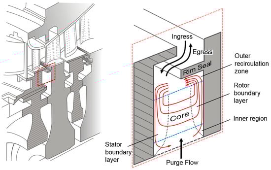
Figure 1.
Turbine stage and simplified model of flow structure.
A sealing effectiveness, related to the mass flow rates of the ingress and the purge flow, is used to compare the performance of different seals. This effectiveness is usually determined experimentally by seeding the sealing air with a tracer gas and measuring the concentration at the surface of the stator. Although there has been considerable research into measuring and predicting this sealing effectiveness, there has been far less attention paid to determining the influence of ingress on the temperature of the rotor.
In the research described here, experimental measurements are made in a turbine rig with 1.5 stages, i.e., stator-rotor-stator. Concentration measurements on the two stators and temperature measurements on the two sides of the rotor are used to determine the sealing effectiveness and adiabatic effectiveness respectively. A nondimensional buffer parameter, Ψ, links the appropriate effectiveness on the stator and rotor. Differences in the radial distribution of swirl upstream and downstream of the rotor are linked to differences in Ψ for the two wheel-spaces.
2. Brief Review of Relevant Research
Scobie et al. [1] and Chew et al. [2] have reviewed the scholarly literature related to ingress. Articles directly related to the effect of ingress on the rotor are discussed below.
Chew et al. [3] presented an experimental and computational study of ingress and their results showed that the purge shields the rotor disc from the ingested flow. Pountney et al. [4] used transient heat-transfer experiments in a one-stage turbine rig to determine the effect of ingress on the rotor. Concentration measurements on the stator were used to determine the amount of ingress and a thermochromic liquid crystal was used to measure the adiabatic effectiveness of the rotor. The measurements showed that significant ingress could exist while the rotor was not affected. Cho et al. [5] used infra-red sensors to determine the adiabatic rotor temperature, and a theoretical model published by Mear et al. [6] agreed well with the measurements.
Figure 1 shows the model used by Owen et al. [7] to derive equations for the adiabatic effectiveness and the adiabatic rotor temperature when ingress occurs; the theoretical effectiveness curves agreed closely with the values measured by Cho et al. [5]. This theoretical model [7] assumed there was a rotating core of inviscid fluid separating thin boundary layers on both the rotor and stator, and that this fluid-dynamic structure was not significantly influenced by ingress (this assumption may not be valid for the downstream wheel-space where, as shown below, ingress can affect the swirl ratio). Another assumption was that fully-mixed flow entered the wheel-space, meaning the concentration and enthalpy within the stator boundary layer was equal to that in the core and independent of the radius. The model showed that only a fraction of the fluid ingested through the rim seal penetrated beyond a mixing region at the periphery of the wheel-space; further, there could be an exchange of enthalpy between the ingress and the cooling flow despite no ingested fluid entering the wheel-space.
3. Experimental Rig and Instrumentation
The experimental study was conducted using the turbine rig at the University of Bath, which operates under fluid-dynamically scaled conditions to model the flow and heat transfer in the engine. Figure 2 illustrates the 1.5-stage test section with further details given by Patinios et al. [8]. The turbine section featured 32 upstream vanes, 48 rotor blades and 32 downstream vanes. The rotor disc and vanes were manufactured as a blisc and 180° bladed-rings, respectively, each machined from a single piece of titanium. The rotor was designed to operate beyond 6000 rpm, but in the experiments reported here, the rotational speeds were 3000 and 4000 rpm (corresponding to Reϕ = 7.2 × 10⁵ and 106). The Mach numbers at the vane exit were 0.3 and 0.4. A dynamometer was used to absorb the generated power. The characteristic diameter of the disc was 380 mm and the height of the annulus was 25 mm. Static pressure taps on the hub platform, spanning the vane exit both upstream and downstream of the rotor, provided the pressure variation in the annulus; these are described in detail by Patinios et al. [8].
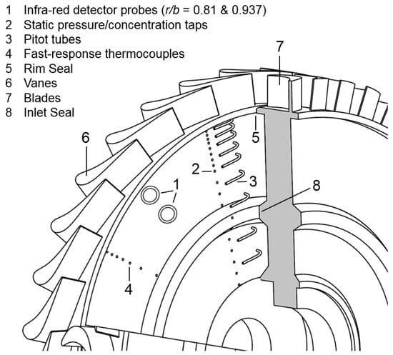
Figure 2.
Test section and instrumentation.
The radial-clearance seals used in the experiments are shown in Figure 3 and dimensions are given in Table 1. The gap ratio was large enough to ensure the stator and rotor boundary layers were separated by a rotating core in the wheel-space.
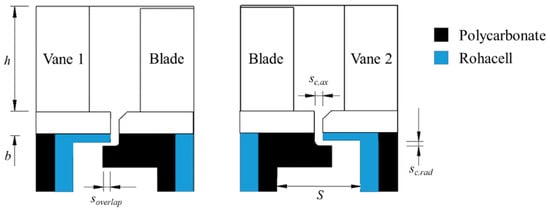
Figure 3.
Single radial-clearance rim seals.

Table 1.
List of geometric parameters.
A composite cover-plate made from two 5-mm-thick discs was attached to either surface of the titanium rotor to achieve quasi-adiabatic boundary conditions for the experiments. The discs in the composite exposed to the flow, including the radial-clearance seal features, were made from polycarbonate (ρ = 1250 kg/m3, ks = 0.2 W/m∙K and cp = 1200 J/kg∙K). The inner surface was insulated using Rohacell 51 foam (ρ = 75 kg/m3, ks = 0.03 W/m∙K and cp = 1225 J/kg∙K). On the stator surfaces, Rohacell was used to minimise the heat loss, and polycarbonate backing plates were used for assembly purposes.
Purge flow was introduced to the wheel-spaces through annular-shaped inlet seals at a low radius (r/b = 0.65), as shown in Figure 2. The purge flow rate was controlled and measured by means of valves; mass-flow meters monitored flow to an uncertainty of ±1%. Pitot tubes and static pressure taps distributed over the disc radius on the surfaces of the two stators were used to measure the swirl ratio in the core (see Figure 2).
The sealing flow was seeded with 1% carbon dioxide. The concentration of CO2 was measured in both the annulus (unseeded) and at entry to the wheel-space, co, using a dual-channel multi-gas analyser (9000MGA from Signal Group, Camberley, Surrey, UK). The radial variation of the concentration along the stator (cs) was measured through 15 hypodermic tubes of diameter 1.6 mm, located between 0.65 ≤ r/b ≤ 0.993. Reference points were located at two radii upstream (r/b = 0.924 and 0.850) and downstream (r/b = 0.941 and 0.800). Carbon dioxide was extracted using a pump to an infrared analyzer; typically, gas concentration measurements were time-averaged over 10 seconds. The uncertainty in gas concentration was 0.015%, as discussed in detail by Patinios et al. [8].
The ratio of mainstream-to-purge flows in the experiments was >10, and heating the annulus flow was costly and a significant design challenge. Consequently, the transient heat transfer testing used annulus flow at ambient temperature and heated sealing flow, which is obviously the reverse to that in the engine. A near step change of 30 °C in the temperature of the purge was created using a wire mesh and a 6kW power source. Two flush-mounted infrared (IR) sensors on the stator wall were used to measure the temperature history of the rotor discs at two different radial locations, r/b = 0.81 and 0.937, as illustrated in Figure 2. Data was collected by the sensors at 10 Hz with a measurement uncertainty < 0.2 °C. The sensors were calibrated in a small-scale wind tunnel, using a copper block as a substrate with an embedded thermocouple; in order to achieve a consistent emissivity, the surface of the copper block was coated with SPBB (from Hallcrest, Flintshire, UK, emissivity = 0.96), which is the same black paint used on the rotor surface. More details of the IR sensors and their calibration are given in Cho et al. [9]. The radiation was collected from an area 6.7 mm in diameter on the rotor surface.
Fast-response thermocouples at six radii and one circumferential location were used to measure the air temperature in the core of the wheel-space, as shown in Figure 2. The K-type thermocouples used unsheathed wire of diameter 0.025 mm [4]. The thermocouple voltages were acquired using a USB-9213 input module (from National Instrument Corporation Ltd., Newbury, Berkshire, United Kingdom) with a pre-calibrated platinum–resistance thermometer. A high-velocity calibration tunnel was used to assess the recovery factor (0.78) and time response (4 ms) of the thermocouples; the temperature uncertainty was 0.1 °C [4].
Measurements of effectiveness (as defined in the next section) on the stator and rotor in both the upstream and downstream wheel-spaces are presented in Section 5. The data in the upstream wheel-space was qualitatively similar to those presented by Owen et al. [7] using a one-stage rig. There are geometric differences in the nozzle guide vane, rotor blade and seal geometries used between this one-stage rig and the 1.5-stage described here.
4. Theoretical Models and Data Analysis
4.1. Adiabatic Effectiveness of the Rotor
If frictional effects are negligible, the adiabatic rotor effectiveness, εr, can be defined as:
where H’ is total enthalpy of the rotor when frictional effects are neglected, Hi is the total enthalpy of the ingress and Ho is the total enthalpy of the purge flow.
It was shown by Owen et al. [7] that εr is related to the sealing effectiveness, εs, and the buffer parameter, Ψ, by:
The buffer parameter is defined as:
where is the purge mass flow rate, is the flow rate in the rotor boundary layer and f’ is an empirical constant. From the conservation of mass:
where , the flow rate in the stator boundary layer, is equal to the flow rate of fluid entrained into the rotor boundary layer. Hence:
and it can be seen that, for a given purge flow, Ψ increases as decreases.
A buffer effect, Δε (also used by Mear et al. [6]), can be defined as:
It follows from Equation (2) that:
Hence, Δε increases as Ψ increases and as εs decreases.
The values of Ψ can be correlated using the analysis presented by Owen et al. [7]:
where and B are the constants determined from the model and λT,o is the turbulent flow parameter, which is defined as:
The inviscid purge flow parameter, Φo, is also used and defined as:
where U is the mass-weighted average velocity through the rim-seal clearance and other symbols are defined in the Nomenclature.
The relationship between Φo and λT,o is given by:
Coincidentally, for the experiments in this paper, λT,o ≈ Φo. Therefore, Equation (8) can be rewritten as:
4.2. Sealing Effectiveness of the Stator
As mentioned in Section 3, the sealing effectiveness was determined using concentration measurements, calculated using:
where ci is the concentration of the ingress that is measured in the annulus, cs is the concentration measurements on the stator and co is the concentration of the purge air.
The concentration measurements were correlated using the effectiveness equation for externally-induced ingress [10,11]:
where Φmin is the minimum value of Φo needed to prevent ingress, and Γc is the ratio of the discharge coefficients for ingress and egress.
4.3. Calculation of Buffer Parameter Ψ
For an adiabatic steady rotor-stator system, it was shown in Reference [7] that:
where Hi, Ho and Hs are the total enthalpies of the annulus flow, the purge flow and the stator boundary layer flow, respectively, is the purge mass flow rate, εs the stator effectiveness measured using the concentration, and Wr the work exerted by the rotating disc from r = a to r = b.
Equation (15) can be rewritten in terms of temperature as:
where Ts,t, Ti,t and To,t are the total-temperatures of the stator boundary layer flow, the annulus flow and the purge flow, respectively.
If the steady-state total-temperature of the purge flow is changed by an increment ΔTo,t, then the total-temperature in the stator boundary layer will be changed by ΔTs,t where:
Owen et al. [7] also presented an equation to calculate the adiabatic rotor temperature, which is rewritten as:
This can be rearranged to become:
Therefore, between two steady states:
and from Equations (17) and (20):
ΔTs,t and ΔTr,ad can be calculated from transient temperature measurements in the wheel-spaces and on the rotor surfaces, and εs can be determined from concentration measurements. The value of the buffer parameter, Ψ, can then be acquired using:
Note that Ψ can only be calculated when 0 < εs < 1.
4.4. Maximum Likelihood Estimation (MLE) Analysis of Transient Temperature Measurements
MLE is a statistical method for estimating the value of parameters from a given data set, and details of the method are provided by Davison [12] and Silvey [13]. In order to calculate the buffer parameter, MLE is used here to estimate ΔTs,t and ΔTr,ad from the transient temperatures measured in the wheel-spaces and on the rotor surfaces.
A likelihood probability density function is developed, assuming the experimental error of the temperature measurements is normally distributed, with zero mean and a standard deviation σ, hence Texp ≈ (Ttrue, σ2), where denotes a normal distribution. Texp and Ttrue are the measured and true values of the temperatures. The likelihood function is expressed as:
where n is the number of data points. Instead of maximising P to find the most likely values of parameters, it is more convenient to minimize l, the negative logarithm of P, where:
The minimisation is achieved using Newton’s method, and the final term can be related to the least-square method.
For the experiments discussed here, the measured temperatures in the core and on the rotor surface are Texp. Each experiment lasted around 15 minutes, and only the measurements in the last 7.5 minutes were used. The true temperature was assumed to be an exponential function where:
and Tinf, D and E are optimised to minimize . The optimised standard deviation between the measured and true temperatures, σ, is about 0.1 °C. Note that, when t → ∞, Ttrue → Tinf. By applying the analysis to the transient air temperature measurements (Ts,exp) and the transient disc surface temperature measurements (Tr,exp), Ts,inf and Tr,inf can be acquired. Therefore, the temperature differences between the initial steady-state and the steady-state when t → ∞ can be calculated using:
where Ts,inf and Tr,inf are the extrapolated temperatures at infinity, and Ts,ini and Tr,ini are the initial temperatures.
Figure 4 shows the measurements and the “true” temperature from MLE for data in the upstream wheel-space at Φo = 0.0265. Ts,inf, Ts,ini, Tr,inf and Tr,ini are also shown using the indicated symbols.
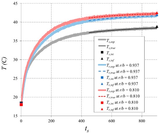
Figure 4.
Transient temperature measurements and “true” temperature from MLE: upstream wheel-space and Φo = 0.0265.
5. Discussion of Experimental Results
This section is divided into three parts. Section 5.1 and Section 5.2 describe the experimental measurements of the swirl and the sealing effectiveness, respectively. Section 5.3 describes measurements of adiabatic effectiveness from transient temperature measurements on the rotor and the rotating core of the wheel-space; the data reduction includes yields the nondimensional buffer parameter, Ψ.
5.1. Swirl Ratios in the Core
As discussed in Section 4.1, Ψ is related to the mass flow rate in the stator boundary layer (or the entrainment into the boundary layer of the rotor) and this is shown to be influenced by the swirl ratio in the core [14]. Therefore, it is of interest to measure the swirl velocities in both the upstream and downstream wheel-spaces.
The swirl ratio is defined as:
It was shown in Reference [14] that the swirl ratio, β, in a rotor-stator system depends on the turbulent flow parameter, and that:
where f denotes a functional relationship, β* is the value of β when λt = 0, and λt is the local turbulent flow parameter defined as:
For a range of flow rates, the swirl ratio in the rig was measured at values of r/b between 0.65 and 0.958 at Reϕ = 106 and 7.2 × 10⁵. The values of β at r/b = 0.825 and 0.958, where the temperatures were measured, were obtained via interpolation of the experimental data. Figure 5 and Figure 6 show the measured values of β/β* versus λt and β* versus r/b, respectively, in both wheel-spaces. The swirl ratio in the core increased with increasing radius and with decreasing purge. For the range of λt relevant to the heat transfer measurements, the results presented in these figures were limited to λt < 0.080 and 0.046 for the upstream and downstream cases, respectively. The swirl correlation, which was linear over these limited ranges, is given by:
where C = 4.09 and 4.53 for the upstream and downstream of the rotor, respectively. The root-mean-square errors were 0.0049 and 0.0085, respectively.
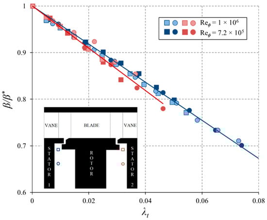
Figure 5.
Variation of β/β* with λt for upstream and downstream wheel-spaces (symbols: data; lines: swirl correlations).
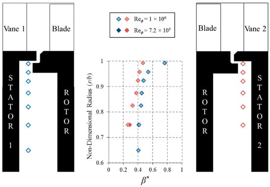
Figure 6.
Variation of β* with r/b for upstream and downstream wheel-spaces.
The values of β* versus r/b in Figure 6 show very different distributions for the two wheel-spaces. Externally-induced ingress was dominant upstream and β* → 1 as r/b → 1. This is consistent with the boundary-layer predictions of Mear [15] who showed (for a closed wheel-space without ingress) that β* →1 as r/b →1. For the downstream case, where the swirl in the annulus was low, the angular momentum of the ingested fluid is believed to be the reason for the smaller values of β*.
5.2. Sealing Effectiveness
Figure 7 shows the sealing effectiveness, εs, obtained using measurements of concentration on both the upstream and downstream stators. The abscissa is Φo and the εs results were correlated using Equation (14). The values of Γc and Φmin were 1.32 and 0.0526, respectively, for the upstream case and 0.0895 and 0.0400 downstream. As found in previous experiments, e.g., Reference [8], there was no significant variation of effectiveness with radius. For the upstream wheel-space, the fits between the effectiveness curve and the experimental data were not as good as those obtained in previous experiments. This is attributed, in part at least, to the polycarbonate seals and the layer of Rohacell on the underside of the seal attached to the stator. It is shown below that the sealing effectiveness for the downstream wheel-space was significantly higher than that in the upstream wheel-space. This was attributed to the reduced circumferential pressure variation in the downstream annulus.
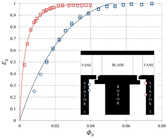
Figure 7.
Variation of εs with Φo for upstream and downstream wheel-spaces (Reϕ = 7.2 × 10⁵). (Symbols: data; lines: Externally-induced effectiveness correlation).
The degree of ingress in the downstream wheel-space depends on the rotor and vane geometries, stage reaction and flow coefficient. There are therefore differences between the flow structure through the upstream and downstream seals. In the downstream case, the egress from the rotor side creates an axisymmetric jet (or fluid “barrier”) that the ingress stream tubes in the mainstream flow must cross before fluid is ingested into the wheel-space; this leads to re-ingestion of the egress into the downstream wheel-space. Consequently, this creates an increase in the sealing effectiveness in the downstream wheel-space relative to the upstream one. Moreover, as shown in Patinios et al. [8], the circumferential pressure variation near the downstream rim seal was much lower than that near the upstream seal, which causes a further increase of the sealing effectiveness in the downstream wheel-space.
5.3. Adiabatic Effectiveness of the Rotor
It was shown in Section 4.1 that the adiabatic rotor effectiveness, εr, is related to the stator effectiveness, εs, and the buffer parameter, Ψ, by Equation (2). Ψ can be determined using the transient temperature measurements, as shown in Section 4.3 and Section 4.4. Distributions of Ψ with Φo for the wheel-spaces upstream and downstream of the rotor are plotted in Figure 8. It was deduced from Equation (5) that, for a given superposed flow, Ψ increases as decreases; meanwhile, , which is affected by the swirl ratio in the wheel-space core, is equal to the entrainment flow rate into the boundary layer on the rotor. The lower swirl ratio in the downstream wheel-space indicates lower and hence a higher buffer ratio. In both wheel-spaces, there is a critical Φo at which Ψ = 1; above this critical Φo, ingress has no effect on the rotor temperature. As shown in Reference [7], Ψ should be a function of r/b, but the measurements shown in Figure 8 do not have sufficient accuracy to show a sensitivity to radius.
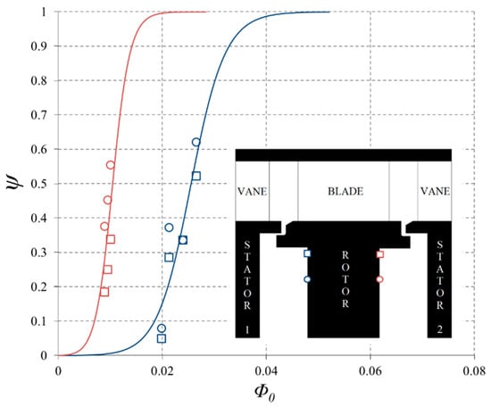
Figure 8.
Variation of ψ with Φo in wheel-spaces upstream and downstream of the rotor (Reϕ = 7.2 × 10⁵). (Symbols: data; lines: fitted theoretical curves).
Distributions of εr with Φo for both wheel-spaces are plotted in Figure 9; the curves of εs, correlated using Equation (14), are also shown in this figure. It can be seen that Δε, the difference between εr and εs, was larger for the upstream wheel-space than for the downstream one. It was shown from Equation (7) that Δε increases as Ψ increases and as εs decreases; in Figure 9, the effect of the change in εs between the wheel-spaces was larger than the effect of the change in Ψ. In both wheel-spaces, εr reached unity at a non-dimensional purge flow rate Φo < Φmin, i.e., εr = 1 when εs < 1.
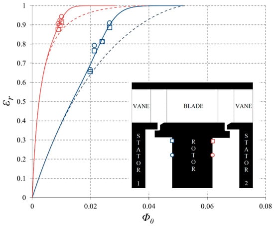
Figure 9.
Variation of εr with Φo in wheel-spaces upstream and downstream of the rotor (Reϕ = 7.2 × 10⁵). (Symbols: data; broken lines: EI effectiveness correlation; solid line: adiabatic rotor effectiveness using the fitted Ψ).
The analysis given in Reference [7] can account for frictional effects; these have been neglected in the analysis because in the experiments conducted here the temperature rise due to frictional heating was <0.1 °C. In gas turbines, the rotor temperature can increase as much as 40 °C from direct frictional heating, which can influence the operating life of engine components under high levels of stress. The buffer effect mitigates the detrimental influence of both hot-gas ingestion and frictional heating.
6. Conclusions
This paper reports the first experimental study of the effect of ingress and purge flow on the adiabatic temperatures of both upstream and downstream surfaces of the rotor in a gas-turbine rig. The experimental results and the theoretical model discussed in this paper have practical relevance for the design of secondary-air systems in both aero-engines and industrial gas turbines.
Measurements of concentration and swirl have been obtained in wheel-spaces upstream and downstream of the rotor in a turbine rig. These experiments have been used to quantify the effect of the purge flow rate on the effectiveness of radial-overlap seals. In the transient heating tests, the temperature of the purge flow was increased by a wire mesh and power supply, and the mainstream flow was kept at the ambient temperature. The temperature history of an insulated rotor was measured using infra-red sensors; the extrapolated steady-state temperatures were used to determine a buffer parameter, which, in conjunction with a theoretical model, yielded the variation of the adiabatic effectiveness with purge. The model discussed in this paper has direct practical relevance to the design of secondary-air systems in aero-engines.
The main conclusions are as follows:
- The sealing effectiveness for the downstream wheel-space was larger than for the upstream one; this was attributed to the fact that the circumferential variation of pressure (which is the driver of externally-induced ingress) in the annulus downstream of the blades was much smaller than that upstream.
- In the core of both wheel-spaces, the swirl ratio, which increased with increasing radius and with decreasing purge flow rate, could be correlated with the local turbulent flow parameter, λt. However, the swirl ratio in the downstream wheel-space was smaller than that in the upstream one; this was attributed to the fact that the swirl in the annulus downstream of the blades was much smaller than that upstream.
- A maximum likelihood estimation analysis was applied successfully to extrapolate transient temperature measurements in the core and rotor surfaces to determine the buffer parameter, Ψ, in both upstream and downstream wheel-spaces.
- Using the calculated values of Ψ for both wheel-spaces, there was mainly good qualitative agreement between the experimental and theoretical variations of rotor effectiveness with non-dimensional purge.
- It was shown that the buffer effect, Δε, of the purge flow was larger for the upstream seal than for the downstream one; this was attributed to the fact that the sealing effectiveness for the upstream wheel-space was lower than the downstream one.
Author Contributions
Conceptualization, methodology and formal analysis, H.T., J.M.O. and G.D.L.; investigation and resources, G.C. and M.P.; writing and visualization, H.T., J.A.S., C.M.S., J.M.O. and G.D.L.; supervision, J.A.S., C.M.S., J.M.O. and G.D.L.; funding acquisition, C.M.S. and G.D.L.
Funding
This research received no external funding.
Acknowledgments
The research described here was supported by the Engineering and Physical Sciences Research Council (EPSRC). Data access: Due to confidentiality agreements with research collaborators, supporting data can only be made available to bona fide researchers subject to a nondisclosure agreement. Details of how to request access are available at the University of Bath data archive website (http://dx.doi.org/10.15125/BATH-00116).
Conflicts of Interest
The authors declare no conflict of interest.
Nomenclature
| a | inner radius of rotor |
| A,B | constants |
| b | outer radius of rotor |
| c | concentration |
| cp | specific heat at constant pressure |
| C,D,E | constants |
| Cw,o | nondimensional flow rate (= o/μb) |
| f | function relationship between β and β* |
| f’ | empirical constant |
| G | gap ratio (= S/b) |
| Gc | seal-clearance ratio (= sc,ax/b) |
| H | total enthalpy |
| H’ | total enthalpy of rotor when frictional effects are neglected |
| ks | thermal conductivity of solid |
| l | negative logarithm of likelihood function |
| mass flow rate | |
| n | number of data points |
| P | likelihood function |
| r | radius |
| R | recovery factor |
| Reϕ | rotational Reynolds number (= ρΩb2/μ) |
| sc,ax | axial clearance of seals |
| sc,rad | radial clearance of seals |
| soverlap | axial overlap of seals |
| S | axial space between rotor and stator |
| t | time |
| T | temperature |
| U | bulk-mean velocity through rim-seal clearance (= o/2πρbsc,ax) |
| Vϕ | tangential velocity in wheel-spaces |
| Wr | work done by the rotor from r = a to r = b |
| β | swirl ratio in wheel-space (= Vϕ/Ωr) |
| β* | swirl ratio when λt = 0 |
| Γc | ratio of discharge coefficients |
| ΔT | difference between initial and extrapolated steady-state temperatures |
| Δε | buffer effect (= εr − εs) |
| εr | adiabatic effectiveness of rotor (= (H’ − Hi)/(Ho − Hi)) |
| εs | concentration effectiveness of stator (= (cs − ci)/(co − ci)) |
| Θo | ratio of flow parameters (= Φo/Φmin) |
| λT,o | turbulent flow parameter (= Cw,o Reϕ−0.8) |
| λt | local turbulent flow parameter (= λT,o(r/b)−13/5) |
| μ | dynamic viscosity |
| ρ | density |
| σ | standard deviation from maximum likelihood estimation |
| Φo | nondimensional flow parameter (= U/ |
| Φmin | value of Φo when there is no ingress |
| Ψ | buffer parameter (= f’(o/r)) |
| Ω | angular velocity of rotor |
| Subscripts | |
| ad | adiabatic |
| exp | experimental measurements |
| i | ingress |
| inf | extrapolated steady-state temperature |
| ini | initial steady-state temperature |
| true | “true” values from maximum likelihood estimation |
| o | purge flow |
| r | rotor |
| s | stator |
| t | total values |
References
- Scobie, J.A.; Sangan, C.M.; Owen, J.M.; Lock, G.D. Review of Ingress in Gas Turbines. ASME J. Eng. Gas Turbines Power 2016, 138, 120801. [Google Scholar] [CrossRef]
- Chew, J.W.; Gao, F.; Palermo, D.M. Flow Mechanisms in Axial Turbine Rim Sealing. Proc. Inst. Mech. Eng. Part C J. Mech. Eng. Sci. 2018, 6, 0954406218784612. [Google Scholar] [CrossRef]
- Chew, J.W.; Green, T.; Turner, A.B. Rim Sealing of Rotor-Stator Wheelspaces in the Presence of External Flow. In ASME 1994 Turbo Expo Volume 1: Turbomachinery, Paper 94-GT-126; American Society of Mechanical Engineers: New York, NY, USA, 1994. [Google Scholar]
- Pountney, O.J.; Sangan, C.M.; Lock, G.D.; Owen, J.M. Effect of Ingestion on Temperature of Turbine Disks. ASME J. Turbomach. 2013, 135, 051010. [Google Scholar] [CrossRef]
- Cho, G.; Sangan, C.M.; Owen, J.M.; Lock, G.D. Effect of Ingress on Turbine Discs. ASME J. Eng. Gas Turbines Power 2016, 138, 042502. [Google Scholar] [CrossRef]
- Mear, L.I.; Owen, J.M.; Lock, G.D. Theoretical Model to Determine Effect of Ingress on Turbine Disks. ASME J. Eng. Gas Turbines Power 2016, 138, 032502. [Google Scholar] [CrossRef]
- Owen, J.M.; Tang, H.; Lock, G.D. Model of Effect of Hot Gas Ingress on Temperatures of Turbine Disks. ASME J. Eng. Gas Turbines Power 2019, 141, 012501. [Google Scholar] [CrossRef]
- Patinios, M.; Scobie, J.A.; Sangan, C.M.; Lock, G.D. Performance of Rim-Seals in Upstream and Downstream Cavities over a Range of Flow Coefficients. Int. J. Turbomach. Propuls. Power 2017, 2, 21. [Google Scholar] [CrossRef]
- Cho, G.; Tang, H.; Owen, J.M.; Lock, G.D. On the Measurement and Analysis of Data from Transient Heat Transfer. Int. J. Heat Mass Transf. 2016, 98, 268–276. [Google Scholar] [CrossRef]
- Owen, J.M. Prediction of Ingestion Through Turbine Rim Seals. Part II: Externally Induced and Combined Ingress. ASME J. Turbomach. 2011, 133, 031006. [Google Scholar] [CrossRef]
- Sangan, C.M.; Pountney, O.J.; Zhou, K.; Wilson, M.; Owen, J.M.; Lock, G.D. Experimental Measurements of Ingestion Through Turbine Rim Seals. Part 1: Externally-Induced Ingress. ASME J. Turbomach. 2013, 135, 021012. [Google Scholar] [CrossRef]
- Davison, A.C. Statistical Models; Cambridge University Press: Cambridge, UK, 2003. [Google Scholar]
- Silvey, S.D. Statistical Inference; Chapman and Hall: London, UK, 1975. [Google Scholar]
- Owen, J.M.; Rogers, R.H. Flow and Heat Transfer in Rotating-Disc. Systems, Volume 1: Rotor-Stator Systems; Research Studies Press: Taunton, UK; John Wiley: New York, NY, USA, 1989. [Google Scholar]
- Mear, L.I. Theoretical Modelling of Flow in Rotor-Stator Systems. Ph.D. Thesis, University of Bath, Bath, UK, 2015. [Google Scholar]
© 2019 by the authors. Licensee MDPI, Basel, Switzerland. This article is an open access article distributed under the terms and conditions of the Creative Commons Attribution (CC BY) license (http://creativecommons.org/licenses/by/4.0/).