Abstract
With the increasing power output of aero-engines, combustor hot-gas mass flow rate and temperature continue to rise, posing more severe challenges to combustor structural cooling design. To enhance the film-cooling performance of the Z-profile feature in a reverse-flow combustor, this study performs a multi-parameter numerical optimization by integrating computational fluid dynamics (CFD), a radial basis function neural network (RBFNN), and a genetic algorithm (GA). The hole inclination angle, hole pitch, row spacing, and the distance between the first-row holes and the hot-side wall are selected as design variables, and the area-averaged adiabatic film-cooling effectiveness over a critical downstream region is adopted as the optimization objective. The RBFNN surrogate model trained on 750 CFD samples exhibits high predictive accuracy (correlation coefficient (R > 0.999)). The GA converges after approximately 50 generations and identifies an optimal configuration (Opt C). Numerical results indicate that Opt C produces more favorable vortex organization and near-wall flow characteristics, thereby achieving superior cooling performance in the target region; its average adiabatic film-cooling effectiveness is improved by 7.01% and 9.64% relative to the reference configurations Ref D and Ref E, respectively.
1. Introduction
As aero-engines evolve toward higher thrust-to-weight ratios, higher thermal efficiency, and lower emissions, combustor pressure and outlet temperature continue to increase, subjecting hot-end components such as the liner and transition duct to more severe thermal loads. To ensure safe service of hot-section structures, aero-engines typically employ multiple cooling and thermal protection technologies in a coordinated manner, including internal convective cooling, impingement cooling, film cooling, and thermal barrier coatings. Internal convection and impingement cooling are primarily used to reduce the substrate temperature, while thermal barrier coatings, as an auxiliary thermal protection measure, can to some extent decrease the heat flux conducted into the substrate. In contrast, film cooling forms a low-temperature protective layer along the wall, directly regulating the heat transfer process between the high-temperature mainstream flow and the structural surface, and it is therefore one of the key determinants of the wall thermal environment [1,2].
For film cooling, many scholars have conducted in-depth research on it. Shiau et al. [3] conducted a parametric experimental study on endwall film cooling for a transonic vane and reported that increasing the mass flow ratio and density ratio improves the cooling effectiveness; however, shock waves can reconfigure the endwall crossflow and thereby deteriorate local cooling performance. Wilhelm [4] investigated the tip film-cooling performance by using a low-speed axial-turbine rig in conjunction with pressure-sensitive paint (PSP) measurements. The results showed that inlet swirl reduces the film-cooling effectiveness at low mass flow ratios, whereas at high mass flow ratios it enhances the cooling performance and outperforms the case with axial inflow. Zhang et al. [5] simulated endwall lateral pressure gradients using a curved constant-width passage and combined experiments and simulations to investigate compound-angle fan-shaped holes, demonstrating that for blowing ratios from 1.0 to 3.0, the coupling between large compound angles and endwall crossflow strengthens the single kidney vortex, lifts the coolant jet, and thereby reduces effectiveness. Abdelmohimen [6] numerically examined the arrangement and velocity-ratio effects of two rows of simple holes and compound-angle holes, finding that staggered arrangement at zero azimuth angle is preferable, while an in-line arrangement at a 30° azimuth angle performs best; for a velocity ratio of 2, the compound in-line configuration achieved the largest improvement (approximately 336.5%), whereas compound angles in staggered layouts reduced effectiveness, with the adverse effect becoming more pronounced at higher velocity ratios. Zhang et al. [7] used RANS to compare several trenched holes with lips over blowing ratios of 0.5–2.0 and found that trenching can enhance film cooling by weakening the strength of the counter-rotating vortex pair; lip structures are beneficial at low blowing ratios but may be detrimental at high blowing ratios, with the upper lip having a more pronounced influence Pu et al. [8] analyzed the coupled effects of compound angle, wall curvature, and blowing ratio on the effectiveness and unsteadiness of fan-shaped holes, indicating that a compound angle CA = 30° provides the best effectiveness across conditions, whereas inclined holes on a concave wall increase unsteady fluctuation amplitudes by more than 20%, which may be unfavorable to durability due to material loss. Li [9] combined transient liquid-crystal measurements with numerical simulations to investigate the flow and heat-transfer characteristics of compound-angle holes under different blowing ratios () and crossflow Reynolds numbers (). The results indicate that the discharge coefficient increases with increasing and is more sensitive to under low- conditions. The adiabatic film-cooling effectiveness (η) exhibits a reversed trend with , decreasing at low but increasing at high . The heat transfer coefficient decreases with increasing and increases with increasing Rec; consequently, the net heat-flux reduction overall tends to decrease as increases. Zhang [10] investigated two rows of compound-angle cylindrical film holes on a flat plate, proposing and validating a temperature-inversion method based on one-dimensional transient conduction. By simultaneously obtaining the film cooling effectiveness and heat transfer coefficient, the study found that a larger heat transfer coefficient is associated with a smaller material thermal conductivity. Du [11] employed a DES model to examine the variations in adiabatic film-cooling effectiveness at a blade trailing edge under different incidence angles and blowing ratios. The results showed that the incidence angle can restructure the flow and suppress separation, yet its influence on adiabatic film-cooling effectiveness is nonlinear. Ma et al. [12] performed time-resolved experiments and LES model to analyze the temporal response and fluctuation characteristics of film cooling with different trench geometries. They reported that, in the absence of mainstream oscillations, unsteadiness is governed primarily by near-wall vortex evolution and varies markedly with trench geometry, whereas mainstream oscillations substantially intensify the unsteadiness. Du et al. [13] compared four cooling schemes for a guide vane by combining PSP measurements with numerical simulations under one-engine-inoperative (OEI) conditions. The results indicate that shaped holes, relative to cylindrical holes, can significantly increase the film-cooling effectiveness and pressure-side coverage, with a more pronounced improvement at M = 9.0%. However, when the OEI setting is increased from 100% to 120%, jet lift-off leads to an approximately 4.3% decrease in area-averaged effectiveness. Overall, in recent years, film-cooling research has shifted in terms of geometric parameters from traditional cylindrical holes to fan-shaped holes, compound-angle holes, and more complex shaped configurations such as trenched and lipped holes. In terms of aerodynamic parameters, the focus has expanded from investigations based on a single blowing ratio to coupled studies under realistic operating conditions, incorporating mass flow ratio and density ratio, inlet swirl and incidence angle, as well as endwall lateral pressure gradients and shock-wave interactions.
Meanwhile, to reduce experimental and computational costs, researchers have introduced surrogate models such as deep learning to predict the performance of cooling structures. By integrating artificial neural networks (ANNs) with genetic algorithms (GAs), multi-objective automated optimization of hole geometries and coolant supply parameters has been achieved. Kim [14] performed structural optimization of bent film holes using RANS simulations coupled with a Kriging surrogate model. Taking the injection angles of the two segments and the height of the bending point as design variables, and the spatially averaged film cooling effectiveness as the objective, the study found that at a blowing ratio of 0.5, the optimal bent hole achieved an improvement in average cooling effectiveness of 39.9% and 78.0% compared to the reference bent hole and the standard cylindrical hole, respectively. Yang [15] used an LSTM network to learn the superposition effects of multi-row and multi-hole film cooling, demonstrating that neural networks can rapidly and robustly predict film-cooling effectiveness under complex superposition conditions, thereby replacing certain empirical superposition models. Wang [16] developed a Deconv-NN surrogate model based on CFD data to learn how parameters such as blowing ratio and hole inclination angle affect the two-dimensional distributions of wall temperature and film-cooling effectiveness over a flat plate. The predictions were found to be in close agreement with the CFD results and to exhibit superior accuracy and robustness compared with semi-empirical correlations and methods such as SVM. Targeting applications with large spanwise spacing, Liu [17] performed two rounds of LHS sampling and multi-island algorithm optimization, based on RANS simulations and a Kriging surrogate model, to optimize the exit shape of fan-shaped holes on a flat plate, and they validated the results experimentally. The optimal design was found to favor a larger lateral expansion width and a smaller streamwise exit width, increasing the spatially averaged film-cooling effectiveness by approximately 70% relative to the baseline. Maral [18] employed a GA to minimize the heat transfer coefficient in the turbine blade tip region while reducing leakage losses, thereby achieving an optimized tip profile. Nguyen [19] combined machine learning with a GA to optimize the shape of turbulators, achieving a 20% increase in the convective heat transfer coefficient without a significant increase in pressure drop. Revulagadda [20] developed a Kriging-based surrogate model for a three-dimensional slot-type cooling configuration in a combustor liner and coupled it with a GA to perform multi-objective optimization, thereby improving the cooling effectiveness. Ren et al. [21] coupled an ANN surrogate model with NSGA-II for the multi-objective optimization of fan-shaped film-cooling holes, achieving a 55.8% increase in film-cooling effectiveness and a 14.9% reduction in the maximum equivalent thermal stress. They further indicated that increasing the blowing ratio, length-to-diameter ratio, and streamwise twisting angle can simultaneously enhance cooling performance and alleviate thermal stress. Based on the above, it can be concluded that, with respect to structural optimization, most existing studies have focused on the optimization of film-cooling holes on flat plates and turbine blades.
Although existing studies on film cooling have become relatively mature with respect to hole shaping, injection angles, and mainstream conditions, most investigations are still conducted in simplified flow environments such as flat plates or turbine blades. In contrast, studies targeting circumferentially complex configurations such as combustor liners remain comparatively limited. Owing to the strong coupling between the recirculation zone and the high-temperature mainstream within the combustor, as well as the intense three-dimensional mixing induced by curved surfaces and circumferential hole arrangements, the coolant film is more prone to deflection and breakup, leading to non-uniform coverage and substantially increasing the difficulty of hole-shape and hole-pattern design. Meanwhile, From the perspective of combustor engineering applications, the Z-profile feature hole configuration can effectively guide and distribute the coolant flow within a confined space and is conducive to enhancing near-wall attachment and spanwise spreading, thereby improving the coverage and cooling reliability of liner hot-spot regions.
Therefore, this study focuses on the Z-profile feature film-cooling configuration in a reverse-flow combustor and employs a multi-parameter optimization design methodology that integrates CFD, a radial basis function neural network, and a genetic algorithm. This approach enables global optimization searches under multi-degree-of-freedom and multi-constraint conditions, providing an efficient design paradigm for complex combustor cooling structures.
2. Numerical Simulation Model and Machine Learning Algorithms
2.1. Geometric Model and Parameter Definitions
The film-cooling configuration of the Z-profile feature on the large bend section of a reverse-flow combustor is illustrated in Figure 1 and Figure 2. Here, denotes the distance between the first-row film-hole location and the hot-side wall, is the hole pitch, is the row spacing, and is the hole inclination angle. Figure 3 shows the numerical model used for the calculations.

Figure 1.
Geometric model of the recirculating combustor.
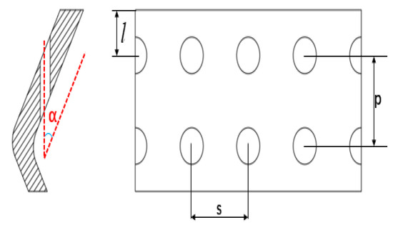
Figure 2.
Schematic diagram of film-cooling hole geometric parameters.
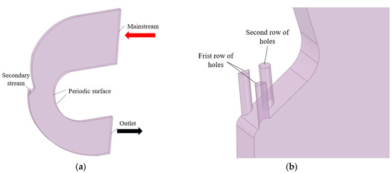
Figure 3.
(a) Schematic diagram of the computational model. (b) Enlarged view of the film-cooling hole region.
Because adiabatic film-cooling effectiveness can directly quantify the capability of a coolant film to attenuate the “effective thermal boundary condition” on the external wall surface, it primarily reflects the influence of hole geometry on key mechanisms such as jet attachment, surface coverage, and mixing. Moreover, it helps isolate the effects of hole design from other non-geometric factors. Therefore, adiabatic film-cooling effectiveness is adopted as the metric for evaluating film-cooling performance.
The adiabatic film-cooling effectiveness is defined as:
where is the mainstream temperature (K), is the adiabatic wall temperature (K), and is the coolant temperature (K).
The mainstream-to-coolant temperature ratio is defined as:
The mainstream-to-coolant blowing ratio is defined as:
where and are the average densities of the coolant and mainstream, ; respectively, and and are the average velocities of the coolant and mainstream, respectively, .
2.2. Numerical Methodology and Mesh Generation
In Fluent 2022, simulations were performed assuming an ideal incompressible fluid. A velocity-inlet boundary condition was prescribed at the mainstream inlet with a velocity of 10 m/s and a temperature of 390 K. The coolant-inlet velocity was determined from the blowing ratio, with an inlet temperature of 300 K. A pressure-outlet boundary condition was applied at the outlet with a static pressure of 101,325 Pa. All wall boundaries were treated as adiabatic. Periodic boundary conditions were imposed on the translational periodic planes. The coupled algorithm was employed to solve the pressure–velocity coupling.
The turbulence model combines the high accuracy of near-wall formulations with the robustness of core-flow modeling. Its principal advantage is that, by accounting for the transport of turbulent shear stress, it can accurately predict flow separation under adverse pressure gradients (e.g., separation as the film-cooling jet issues from the hole). Moreover, it effectively avoids overprediction of eddy viscosity, thereby enabling reliable capture of the vortex structures at the film-hole exit and the associated wall heat transfer [22,23]. Therefore, the turbulence model was adopted in the simulations. To ensure the reliability of the numerical results, second-order discretization schemes were used for both the convection terms and the turbulence equations. Convergence was assessed by requiring that the residuals of all monitored variables fall below 10−6. The mesh was generated in Fluent Meshing 2022 using an all-hexahedral topology. The region around the film-cooling holes was locally refined, and boundary-layer meshes were applied. The resulting mesh is shown in Figure 4.
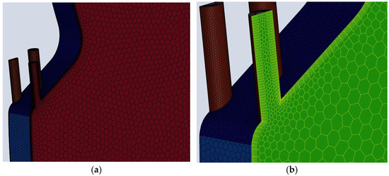
Figure 4.
(a) Mesh generation result. (b) Film-hole region.
Five mesh sets (0.15 million, 0.34 million, 0.64 million, 1.01 million, and 1.97 million cells) were generated to perform a grid-independence study, using the area-averaged wall temperature downstream of the film-cooling holes ( ) as the evaluation metric. The results (Figure 5) indicate that when the mesh size exceeds 0.64 million cells, the variation in the area-averaged wall temperature remains within 0.12%. Therefore, considering both accuracy and computational cost, the mesh with 0.64 million cells was selected for the subsequent simulations.

Figure 5.
Grid independence verification results.
2.3. Numerical Simulations and Model Calibration
2.3.1. Experimental System
In order to ensure the validity of the numerical calculation method, cooling experiments were conducted on a representative Z-profile feature film-cooling configuration prior to the CFD simulations. As shown in Figure 6, the experimental facility consists of four subsystems—an air-supply system, a heating system, a measurement system, and a test section—and comprises components including air compressors (Suzhou Sullair Air Equipment Co., Ltd., Suzhou, China) for the mainstream and coolant passages, storage tanks, control valves, flow meters, a heater, flow-straightening grids, the test section, and pressure and temperature measurement systems. The mainstream air is supplied by a compressor and first enters a high-pressure storage tank to stabilize the pressure. It then passes through a control valve used to regulate the mainstream flow rate and is routed into the heater, where it is heated to the temperature required for the tests. After being conditioned by the flow-straightening grids, the heated flow is delivered to the test section. The coolant air is supplied by a second compressor and sequentially passes through a coolant flow-control valve and a coolant flow meter before entering the test section. In addition to the mainstream and coolant passages, the core of the test section comprises the test channel and the Z-profile feature film-cooling structure fabricated from a low-thermal-conductivity phenolic laminate. An infrared thermography camera was used to measure the wall temperature distribution downstream of the film-cooling holes, and the adiabatic film-cooling effectiveness was then calculated using Equation (1).
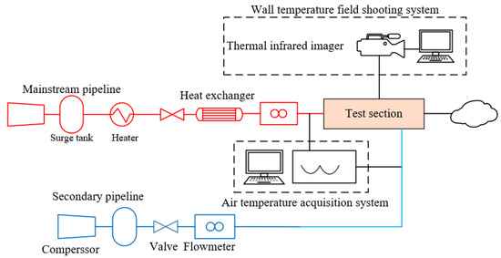
Figure 6.
Schematic of the experimental facility.
Figure 7 shows photographs of the test channel, the Z-profile feature cooling structure, and the film-hole plate. The geometric dimensions are identical to those used in the numerical simulations. Adiabatic film-cooling effectiveness tests were conducted at = 1.3 and = 1.0, consistent with the CFD operating conditions.
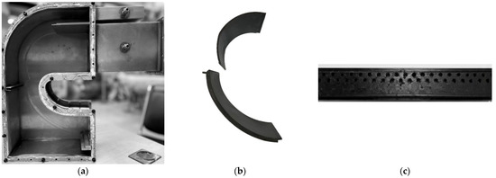
Figure 7.
Photographs of the test channel, the Z-profile feature cooling structure, and the film-hole plate. (a) Test-section channel assembly. (b) Photograph of the Z-profile feature cooling structure. (c) Film-hole plate.
2.3.2. Calibration of Adiabatic Film-Cooling Effectiveness
The numerical results are in good agreement with the experimental measurements in terms of overall trends; however, noticeable quantitative discrepancies persist, and both the rate of change and the attenuation magnitude vary among different regions. Accordingly, the downstream wall surface behind the film-cooling holes was segmented by the streamwise position (X/L) for calibration, and the correction factors for each segment are summarized in Table 1.

Table 1.
Correction factors for different X/L regions.
Figure 8 compares the experimentally measured streamwise distribution of adiabatic film-cooling effectiveness downstream of the film holes with the calibrated numerical results for (p = 1.6) mm, (s = 0.8) mm, (K = 1.3), and (M = 1.0). As shown, the adiabatic effectiveness increases in the near-hole region to a maximum value and then decreases rapidly. In the mid and far downstream regions, it continues to decay gradually and approaches an asymptotic value. The mean error is less than 15%, demonstrating the accuracy of the numerical predictions and the proposed calibration approach.
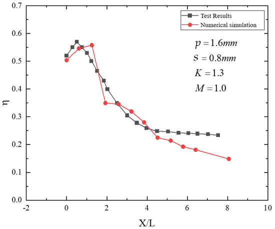
Figure 8.
Comparison between streamwise cooling effectiveness and numerical results.
2.4. Radial Basis Function Neural Network and Genetic Algorithm
The RBFNN is a feedforward neural network with strong global approximation capability. By using radial basis functions as the activation functions of the hidden-layer units, it can nonlinearly map the input space to the output space. The basic mapping form of an RBFNN is given by:
Here, the output is constructed as a weighted superposition of multiple radial basis functions. Each radial basis function is centered at (c_i ci) and responds according to the distance between the input vector and its center.
The Gaussian radial basis function is given by:
When the input vector is far from the center, the Gaussian radial basis function approaches zero (Equation (6)), which reflects the localized nature of radial basis functions.
GA is a global optimization search method inspired by Darwinian evolutionary theory. It encodes candidate solutions as “chromosomes” and iteratively searches for the optimum by mimicking genetic operations observed in nature, such as selection, crossover, and mutation, thereby driving the population (string set) to evolve toward better solutions. A key advantage of GA is that it initiates the search from multiple candidate solutions (a population), providing strong global exploration capability that helps avoid entrapment in local optima. It is also amenable to parallel implementation, making it particularly suitable for complex combinatorial optimization problems.
The GA parameter settings play a critical role in balancing optimization efficiency and global search capability. In this study, the parameters were determined by synthesizing commonly used ranges reported in the literature and the results of multiple preliminary trials; the final settings are listed in Table 2. The crossover probability was set to 0.7 to ensure strong information recombination during evolution, thereby accelerating convergence. The mutation probability was set to 0.01 to maintain population diversity while avoiding excessive random perturbations, preventing the search process from degenerating into random search. The population size was chosen as 50 to provide adequate coverage of the solution space while controlling computational cost. The maximum number of generations was set to 100 to ensure stable convergence within an acceptable computational time.
Table 2.
GA parameter settings.
2.5. Optimization Framework
The optimization procedure for the Z-profile feature film-cooling configuration in the large-bend section is illustrated in Figure 9. Within the prescribed parameter ranges, a large set of CFD samples was generated to train a surrogate model. A radial basis function neural network was then trained and constructed in MATLAB 2022a to develop a predictive model for the average adiabatic film-cooling effectiveness on the downstream wall surface. Subsequently, a GA was employed to perform global optimization under the specified constraints, ultimately yielding the optimal cooling configuration. The overall optimization workflow is shown in Figure 9.
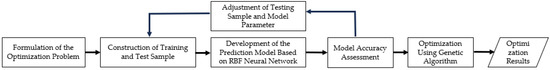
Figure 9.
Optimization workflow.
The hole inclination angle , the distance between the first-row holes and the hot-side wall, the row spacing , and the hole pitch were selected as design variables. The optimization objective was defined as the wall-averaged adiabatic film-cooling effectiveness over the downstream region . This range was chosen because it corresponds to the primary coverage region of a single Z-profile feature film-cooling unit, where the effectiveness varies most markedly and is therefore most representative of cooling performance (As shown in Figure 10).
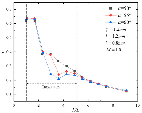
Figure 10.
Streamwise distribution of adiabatic effectiveness downstream of the film holes.
The objective function is defined as:
The geometric-parameter constraints are defined as:
The geometric configuration adopts a staggered arrangement. To obtain a sufficiently diverse sample set, a full-factorial design was employed for the four geometric parameters to define the CFD cases: the hole inclination angle ranged from 50° to 60° with an increment of 2°; the row spacing ranged from 0.8 mm to 1.6 mm with an increment of 0.2 mm; the hole pitch ranged from 0.8 mm to 1.2 mm with an increment of 0.1 mm; and the distance from the first-row holes to the hot-side wall ranged from 0.4 mm to 0.8 mm with an increment of 0.1 mm. As summarized in Table 3, a total of 750 cases were generated for CFD simulations to provide training data. It should be noted that although the inclination angle () in the CFD training samples was generated using discrete values with a 2° increment, during the surrogate-based optimization stage the design variables including () were treated as continuous within their prescribed ranges. The RBFNN provides a continuous mapping, and the GA searches the continuous design space; therefore, the optimal solution may lie between the discrete sampled points.
Table 3.
Ranges of film-hole geometric parameters.
3. Analysis of Training and Optimization Results
3.1. Training Results
During surrogate-model construction, to ensure objectivity in model evaluation and robust generalization, the original dataset was randomly partitioned into a training set and a validation set. Specifically, 80% of the samples were used for training, while the remaining 20% were used for hyperparameter tuning and performance assessment. This strategy preserves the consistency of the underlying data distribution while enabling an effective evaluation of the model on unseen data, thereby mitigating overfitting and ensuring reliability in practical applications. After 750 training iterations (epochs), the radial basis function network was obtained. The training results are shown in Figure 11, with a mean squared error below (1.3 × 10⁻¹²) and a correlation coefficient of (R = 0.9998 ≈ 1), indicating extremely high predictive accuracy.

Figure 11.
(a) Schematic of the validation-set evaluation results. (b) Error training results. (c) Fitting results of the training process.
After constructing the RBF neural network, a genetic algorithm was applied to optimize the downstream film-cooling effectiveness. After approximately 50 generations, the best individual in the population had already approached the final optimum, yielding a maximum cooling effectiveness of 0.7799 (0.7141 after calibration), as shown in Figure 12.
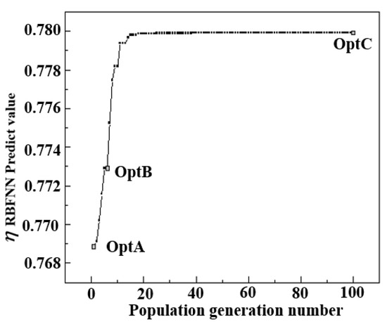
Figure 12.
GA optimization results.
Here, several locally optimal individuals were selected together with representative configurations used for comparison; their geometric parameters and the average cooling effectiveness over the target region are summarized in Table 4. The globally optimal individual is denoted as Opt C.
Table 4.
Geometric parameters and average cooling effectiveness of locally optimal and typical configurations.
3.2. Analysis of Optimization Results
Figure 13 shows the streamwise distributions of film-cooling effectiveness downstream of the holes for the globally optimal configuration Opt C and the reference configurations Ref D and Ref E. As can be observed, the largest differences among the three cases occur within the target region X/L = 0–5.2. For Opt C and Ref D, the effectiveness decreases slowly over X/L = 0–2.5, followed by a rapid decline over X/L = 2.5–5.2. In contrast, Ref E exhibits a slight increase in effectiveness in the near-hole region X/L = 0–0.64, after which it gradually decreases over X/L = 0.64–5.2. In terms of the area-averaged effectiveness over the target region, Opt C is the highest (), followed by Ref D (), with Ref E being the lowest ().
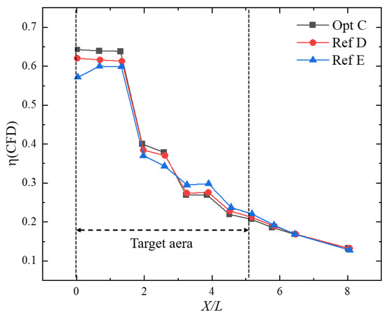
Figure 13.
Film-cooling effectiveness for different optimized configurations.
Figure 14 presents the flow fields on the section passing through the centerline of the first-row holes for the globally optimal configuration Opt C and the reference configurations Ref D and Ref E (the elliptical region denotes the recirculation zone, and the polygonal region indicates the film-covered area). It can be seen that the vortex structures formed between the first-row jet and the wall, as well as those formed between the first-row jet and the mainstream, differ markedly among the three configurations.
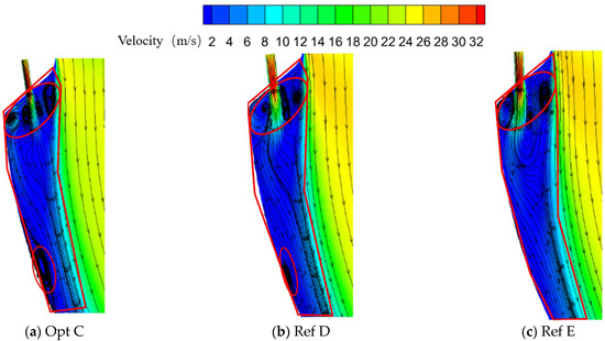
Figure 14.
Flow fields on the section through the centerline of the first-row holes for different optimized configurations.
For the vortex located between the first-row jet and the wall, Opt C places this vortex closer to the initial downstream region of the wall surface. This vortex induces a pronounced deflection of the first-row jet streamlines: the favorable pressure gradient is weakened, and a relatively strong adverse pressure gradient develops near the downstream wall, resulting in a wall-attached vortex. In contrast, under Ref D and Ref E, this vortex is smaller than that in Opt C, located further downstream, and does not exhibit a pronounced adverse pressure-gradient feature.
In the region between the first-row jet and the mainstream, Opt C generates a richer population of small-scale vortices, promoting relative motion between the mainstream and coolant and leading to more thorough mixing. By comparison, Ref D and Ref E exhibit a pair of large-scale, oppositely rotating vortices in this region, which induces mixing between the mainstream and coolant only to a limited extent.
Figure 15 shows the flow fields on the section passing through the centerline of the second-row holes for Opt C and the reference configurations Ref D and Ref E (the elliptical region denotes the recirculation zone, and the polygonal region indicates the film-covered area). Differences are observed in the vortex structures formed between the second-row jet and the wall, as well as between the second-row jet and the mainstream.
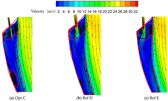
Figure 15.
Flow fields on the section through the centerline of the second-row holes for different optimized configurations.
In the region between the second-row jet and the wall, Opt C forms a pair of counter-rotating vortices, which intensifies mixing between the mainstream and coolant in this region. Moreover, a relatively strong adverse pressure gradient develops near the downstream wall, giving rise to a wall-attached vortex. In contrast, Ref D and Ref E generate only a single vortex in this region, and no pronounced adverse pressure gradient is observed near the downstream wall.
In the region between the second-row jet and the mainstream, all three configurations exhibit a pair of counter-rotating vortices. For Opt C, the vortex adjacent to the coolant side is smaller in size, whereas for Ref E, the corresponding vortex is larger. In all cases, the mainstream and coolant undergo mixing to some extent in this region.
Figure 16 presents the downstream wall temperature fields for the globally optimal configuration Opt C and the reference configurations Ref D and Ref E. The three configurations exhibit noticeable differences in streamwise and spanwise cooling effectiveness, temperature gradients, and the extent of film coverage. Opt C shows a relatively large streamwise temperature gradient and a higher cooling effectiveness in the near-hole region, together with better spanwise uniformity of cooling effectiveness. However, its streamwise effectiveness decays more rapidly, resulting in a comparatively smaller film coverage area. By contrast, Ref D and Ref E yield lower effectiveness in the near-hole region and less uniform spanwise distributions, but their streamwise effectiveness decreases more gradually, leading to a slightly wider film coverage. Nevertheless, in terms of the area-averaged effectiveness over the target region, Opt C remains the highest, followed by Ref D, with Ref E being the lowest.
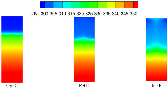
Figure 16.
Downstream wall temperature fields for different optimized configurations.
To elucidate the differences in spanwise uniformity of cooling effectiveness in the initial downstream region of the wall, cross-sectional planes were defined at , , and , where is the width of the plane containing the film holes. The spanwise flow features on these sections were then examined. Figure 17 compares the flow fields for the globally optimal configuration Opt C and the reference configurations Ref D and Ref E, showing substantial differences among the three cases on these planes.
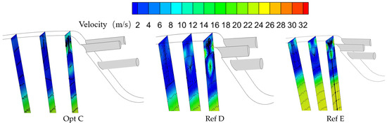
Figure 17.
Spanwise flow fields at X = 0.125L, 0.5L, and 1L downstream of the film holes.
All three configurations exhibit a pair of counter-rotating vortices on these sections. This vortex pair mainly originates between adjacent first-row holes: two neighboring jets attract each other, forming a vortex pair that drives the coolant toward the wall. The size and location of this vortex pair strongly influence the cooling performance in the near-hole region downstream of the film holes. For Opt C, the vortex pair is markedly larger and stronger than that in Ref D and Ref E; consequently, Opt C achieves better average cooling performance and improved spanwise uniformity of cooling effectiveness in the initial downstream region.
4. Conclusions
To achieve an optimized film-cooling design for the Z-profile feature in a reverse-flow combustor, this study developed an optimization framework integrating an RBF neural network, a GA, and CFD. Based on this framework, an optimization study was conducted for the Z-profile feature, leading to the following conclusions:
(1) Using a multi-parameter optimization framework that integrates CFD, an RBFNN surrogate model, and GA-based global search, an optimal design (Opt C) for the Z-type annular film-cooling configuration in a reverse-flow combustor was obtained. Within the target region (X/L = 0–5.2), the area-averaged adiabatic film-cooling effectiveness of Opt C is improved by 7.01% and 9.64% relative to the reference configurations Ref D and Ref E, respectively, demonstrating the effectiveness of coordinated multi-variable optimization in enhancing cooling performance.
(2) A quantitative analysis of the spanwise flow in the initial downstream region shows that Opt C exhibits a higher mean turbulent kinetic energy on the (X = 0.125L) plane than the reference configurations (4.467, 4.191, and 3.954 for Opt C, Ref D, and Ref E, respectively), indicating stronger turbulent fluctuations and enhanced mixing in the near-wall shear layer. This feature is conducive to the spanwise diffusion and spreading of the coolant, thereby improving wall coverage in the initial region and enhancing the uniformity of the spanwise distribution of film-cooling effectiveness.
(3) Comparative numerical results indicate that coordinated optimization of geometric parameters can markedly improve the spanwise coverage and streamwise decay characteristics of the coolant film. The optimized configuration shows superior performance in mixing control and vortex-system organization, highlighting the necessity of refined structural design under the complex flow conditions typical of combustors.
Author Contributions
Methodology, Y.L. and Y.Y.; Data curation, J.Y.; Writing — original draft, J.Y.; Project administration, W.Y.; Funding acquisition, W.Y. All authors have read and agreed to the published version of the manuscript.
Funding
This research received no external funding.
Data Availability Statement
The original contributions presented in this study are included in the article. Further inquiries can be directed to the corresponding author.
Conflicts of Interest
The authors declare no conflicts of interest.
References
- Dutta, S.; Kaur, I.; Singh, P. Review of Film Cooling in Gas Turbines with an Emphasis on Additive Manufacturing-Based Design Evolutions. Energies 2022, 15, 6968. [Google Scholar] [CrossRef]
- Olczak, D.; Jaworski, M. Review of Turbine Cooling Technologies. J. Eng. Gas Turbines Power 2023, 145, 090801. [Google Scholar] [CrossRef]
- Shiau, C.-C.; Sahin, I.; Ullah, I.; Han, J.-C.; Mirzamoghadam, A.V.; Riahi, A.; Stimpson, C. Transonic Turbine Vane Endwall Film Cooling Using PSP Measurement Technique. In Proceedings of the ASME Turbo Expo 2019: Turbomachinery Technical Conference and Exposition, Phoenix, AZ, USA, 17–21 June 2019. [Google Scholar] [CrossRef]
- Wilhelm, M.; Schiffer, H.-P. Experimental Investigation of Rotor Tip Film Cooling at an Axial Turbine with Swirling Inflow Using Pressure Sensitive Paint. Int. J. Turbomach. Propuls. Power 2019, 4, 23. [Google Scholar] [CrossRef]
- Zhang, H.; Wang, Q.; Chen, Z.; Su, X.; Yuan, X. Effects of compound angle on film cooling effectiveness considering endwall lateral pressure gradient. Aerosp. Sci. Technol. 2020, 103, 105923. [Google Scholar] [CrossRef]
- Abdelmohimen, M.A.H.; Badruddin, I.A.; Saleel, C.A.; Khan, T.M.Y.; Kamangar, S. Numerical Analysis of Film Cooling Due to Simple/Compound Angle Hole Combination. Arab. J. Sci. Eng. 2020, 45, 8931–8944. [Google Scholar] [CrossRef]
- Zhang, R.; Zhou, L.; Xing, J.; Luo, C.; Du, X. Numerical evaluation of film cooling performance of transverse trenched holes with shaped lips. Int. Commun. Heat Mass Transf. 2021, 125, 105326. [Google Scholar] [CrossRef]
- Pu, J.; Zhang, T.; Wang, J. Experimental study of combined influences of wall curvature and compound angle on film cooling effectiveness of a fan-shaped film-hole. Int. Commun. Heat Mass Transf. 2022, 130, 105834. [Google Scholar] [CrossRef]
- Li, L.; Liu, C.; Xu, Z.; Zhu, H.R.; Zhang, F. Experimental and numerical research on film cooling characteristics on the compound angle hole. Phys. Fluids 2022, 34, 125128. [Google Scholar] [CrossRef]
- Zhang, M. Determination of Film Cooling Effectiveness and Heat Transfer Coefficient Simultaneously on a Flat Plate. Energies 2022, 15, 4144. [Google Scholar] [CrossRef]
- Du, W.; Luo, L.; Wang, S.; Jiao, Y.; Sunden, B. Film Cooling in the Cutback for Trailing Edge with Different Incident Angles. J. Energy Resour. Technol. 2022, 145, 053201. [Google Scholar] [CrossRef]
- Ma, L.; Wang, M.; Chen, J.; Su, H.; Wang, J.; Yao, R. Experimental and numerical investigations on transient film cooling performances with trenched holes considering mainstream oscillation. Int. J. Heat Mass Transf. 2024, 218, 124799. [Google Scholar] [CrossRef]
- Du, K.; Li, Y.; Chen, Q.; Shan, X.; Liu, C. Experimental and numerical investigations on film cooling characteristics and hole shape improvement of turbine vane at one engine inoperative condition. Int. J. Therm. Sci. 2024, 201, 109044. [Google Scholar] [CrossRef]
- Kim, J.-H.; Kim, K.-Y. Shape optimization of a bended film-cooling hole to enhance cooling effectiveness. J. Therm. Sci. Technol. 2019, 14, JTST0011. [Google Scholar] [CrossRef]
- Yang, L.; Wang, Q.; Huang, K.; Rao, Y. Establishment of a long-short-term-memory model to predict film cooling effectiveness under superposition conditions. Int. J. Heat Mass Transf. 2020, 160, 120231. [Google Scholar] [CrossRef]
- Wang, Y.; Wang, W.; Tao, G.; Zhang, X.; Luo, S.; Cui, J. Two-dimensional film-cooling effectiveness prediction based on deconvolution neural network. Int. Commun. Heat Mass Transf. 2021, 129, 105621. [Google Scholar] [CrossRef]
- Liu, C.; Amei, B.; Yi, Z.; Dawei, C.; Junjun, G.; Ren, D. Surrogate-based optimization and experiment validation of a fan-shaped film cooling hole with a large lateral space. Appl. Therm. Eng. 2022, 207, 118145. [Google Scholar] [CrossRef]
- Maral, H.; Alpman, E.; Kavurmacıoğlu, L.; Camci, C. A genetic algorithm based aerothermal optimization of tip carving for an axial turbine blade. Int. J. Heat Mass Transf. 2019, 143, 118419. [Google Scholar] [CrossRef]
- Nguyen, N.P.; Maghsoudi, E.; Roberts, S.N.; Kwon, B. Shape optimization of pin fin array in a cooling channel using genetic algorithm and machine learning. Int. J. Heat Mass Transf. 2023, 202, 123769. [Google Scholar] [CrossRef]
- Revulagadda, A.P.; Rana, R.; Suresh, B.; Balaji, C.; Pattamatta, A. A multiobjective optimization of 3D-slot jet configuration for enhancement of film cooling in an annular combustor liner. Int. J. Heat Mass Transf. 2024, 218, 124745. [Google Scholar] [CrossRef]
- Ren, S.; Zhu, J.; Cheng, Z.; Wang, X.; Tong, Z.; Qiu, L. Multi-objective optimization of fan-shaped film hole for balancing heat transfer and thermal stress based on ANN and NSGA-II. Int. Commun. Heat Mass Transf. 2025, 165, 109045. [Google Scholar] [CrossRef]
- Belouddane, I.; Hamel, M.; Khorsi, A. Hybrid film cooling geometry analysis with OpenFOAM. Meccanica 2024, 59, 1103–1119. [Google Scholar] [CrossRef]
- Kong, X.; Zhang, Y.; Li, G.; Lu, X.; Zhu, J.; Xu, J. Simulation of flow structure and heat transfer of sweeping jet and film composite cooling on a flat plate. Appl. Therm. Eng. 2022, 213, 118741. [Google Scholar] [CrossRef]


Disclaimer/Publisher’s Note: The statements, opinions and data contained in all publications are solely those of the individual author(s) and contributor(s) and not of MDPI and/or the editor(s). MDPI and/or the editor(s) disclaim responsibility for any injury to people or property resulting from any ideas, methods, instructions or products referred to in the content. |
© 2025 by the authors. Licensee MDPI, Basel, Switzerland. This article is an open access article distributed under the terms and conditions of the Creative Commons Attribution (CC BY) license.