Abstract
In this paper, a finite-time three-axis stabilization controller for an underactuated rigid spacecraft is proposed based on well-designed hierarchical terminal sliding mode surfaces to handle the insufficiency of control effort and disturbances. Firstly, the attitude kinematic of an underactuated rigid spacecraft is parameterized by the w-z representation and the dynamic model with only two orthogonal torque inputs are presented. Secondly, based on the terminal sliding mode theory, a three-hierarchized sliding surface is established. A finite-time stable control law is derived by the Filippov equivalence theorem and the principle of sliding mode control. The finite-time stability is proved by the Lyapunov theory. Finally, the high performance of the proposed control approach is verified through numerical simulations and comparisons with state-of-the-art studies.
1. Introduction
In space missions, actuator failure is invariably unforeseeable [1]. When the number of independent control inputs of a spacecraft is fewer than the number of its degrees of freedom, the spacecraft is said to be underactuated. Meanwhile, the spacecraft is influenced by sun–moon gravitational perturbation [2]. How to control this underactuated system has always been an important and challenging topic in attitude control.
The primary issue confronted in the attitude control of underactuated spacecraft is whether the attitude system of the spacecraft can be controlled without one or two independent control inputs [3]. This problem was resolved by Crouch in 1984. Under the condition where the actuator is a thruster with merely two control inputs, Crouch [4] proposed the sufficient and necessary conditions for the global controllability of an underactuated spacecraft. Additionally, Crouch further proved that if the actuator is a flywheel, the total angular momentum of an underactuated system must be zero. On this foundation, Byrnes and Isidori [5] further demonstrated that a continuous time-invariant control law does not satisfy Brockett’s necessary conditions [6], thus the control law cannot asymptotically stabilize the attitude of underactuated spacecraft. Consequently, in the subsequent research, time-varying and discontinuous control laws were commenced for the attitude control of underactuated spacecraft.
Based on the aforementioned research on the controllability of the attitude system of underactuated spacecraft, the current control approaches can be categorized into two types in accordance with the distinct actuators: one is the underactuated spacecraft with a thruster serving as the actuator; the other is the underactuated spacecraft with a flywheel serving as the actuator. Firstly, the control of the underactuated spacecraft with the thruster as the actuator is presented. Zhang et al. [7] designed a time-varying dynamic feedback controller for such nonlinear underactuated systems by using the auxiliary states generated by time-varying oscillators similar to differential equations and constructing a new Lyapunov-like function. Lu and Meng [8] introduced an underactuated controller in the case of multiple states being driven by a single input. Firstly, based on orbit and attitude models, the input and underactuated characteristics are analyzed. Nadafi and Kabganian [9] designed a robust controller to achieve perfect attitude tracking of an underactuated spacecraft, taking into account saturation and uncertainty. Due to the non-singularity of this design, it can reduce the burden of limiting the initial conditions of the quaternion. Brewer and Tsiotras [10] used the average theory to propose two motion controllers that can stabilize a complete attitude of the underactuated satellite, so that the attitude of the underactuated satellite can achieve exponential stability. Hao et al. [11] studied the rotational decoupling properties of plane axis rotations of rigid bodies using eigenvalue analysis-based methods, and for the application of decoupling properties, applied it to the attitude redirection problem using two-dimensional control. Nadafi and Kabganian [12] proposed a non-singular attitude tracking control that does not require initial conditions to restrict quaternions. According to the Lyapunov criterion and LaSalle invariance theorem, the controller in large angle maneuvering is analyzed. Zou et al. [13] proposed an attitude stability control law for asymmetric underactuated spacecraft, ensuring that the control input is bound and small enough when the initial condition is close to the singular manifold. Tian et al. [14] developed an underactuated tracking controller incorporating an adaptive barrier function to address the underactuated attitude tracking problem of tethered spacecraft. The effectiveness and robustness of the proposed controller were validated through comprehensive simulations. Meng and Lu [15] proposed an intelligent attitude control method for underactuated spacecraft based on thrust vector control technology. Additionally, a control law was designed that utilizes an enhanced coupling strategy and an adaptive fuzzy observer. Simulation results demonstrate that this approach achieves a faster convergence rate. Zhou and Zhang [16] employed time-varying state transformation to convert the underactuated system into a linear time-varying system. Building on this framework, a smooth time-varying state feedback controller was proposed, ensuring exponential convergence of all system states. Finally, the effectiveness of the control law was validated through simulations. Wang [17] analyzed and designed the hierarchical fuzzy system and verified the effectiveness of the hierarchical system through two numerical examples. On this basis, Mon further proposed a hierarchical sliding mode control and Hwang applied it to path tracking [18]. Avanzini [19] addressed the issue of aiming at the fixed axis of the universal body along the inertial fixed direction when only two reaction wheels could exchange angular momentum with the spacecraft platform in the presence of non-zero residual angular momentum. Bai et al. [20] considered the situation where an underactuated rigid spacecraft only has two reaction wheels and studied the design of the attitude controller for the underactuated rigid spacecraft. Yao et al. [21] designed three types of fixed-time controllers to achieve local stability control of the underactuated spacecraft, where the angular velocity and attitude of the underactuated axis could not fully converge to zero. Different from the traditional sliding mode control methods of Surganova [22] and Dao [23] in robot systems, the hierarchical sliding mode control law designed in this paper mainly targets fully underactuated systems rather than systems with power loss. The fundamental difference lies in the significant gap in the controllability of the system. In addition, the control law designed in this paper has strong robustness and strict finite-time convergence characteristics.
The attitude control of an underactuated spacecraft with a flywheel serving as the actuator has also been investigated. Ismail et al. [24], Duan et al. [25], Zhang et al. [26], Alger et al. [27], Ousaloo [28], Jia et al. [29], Golzari et al. [30], and Bunryo et al. [31] employed reaction wheels as actuators in attitude control.
In conclusion, despite extensive research on the attitude control of underactuated spacecrafts, most existing studies reveal that the attitude and angular velocity do not converge to zero but instead approach another constant value. Moreover, due to the complexity of analyzing the stability of intermediate hierarchy sliding variables, hierarchical sliding mode control methods are seldom applied in the control of underactuated spacecrafts. Additionally, prior research has largely focused on achieving asymptotic stability across three axes, with relatively few studies addressing finite-time convergent controllers. To address these gaps, this paper proposes a non-singular finite-time controller for the attitude stabilization of underactuated spacecrafts, based on a hierarchical sliding mode approach:
- (1)
- A sliding surface is constructed through a non-singular terminal sliding mode method, and the hierarchical construction method is enhanced based on conventional hierarchical sliding mode control frameworks. Ultimately, a three-hierarchical non-singular terminal sliding surface is developed to ensure the stability of sliding variables at each hierarchy, thereby achieving finite-time stabilization of the spacecraft attitude.
- (2)
- Compared to some previous studies, the control law designed in this paper can accommodate larger initial attitude without imposing restrictions on the initial conditions. Moreover, good convergence and robustness can still be guaranteed under large initial attitude conditions. This characteristic aligns with practical requirements in spacecraft attitude control.
In summary, most of the existing non-singular terminal sliding mode controllers are mainly designed for full actuated systems or partially failed fault systems, and their control objective is to achieve precise trajectory tracking or stability on all axes. However, for underactuated systems, the fundamental challenge lies in the nonholonomic constraint characteristics of the system, which makes it impossible for continuous time-invariant control laws to achieve asymptotic stability. The method proposed in this paper is specifically constructed for the structural characteristics of underactuated systems. By designing a three-hierarchy sliding mode surface, it actively utilizes and manages this underactuated constraint, ultimately achieving simultaneous finite-time stability of three axes, which is difficult to directly implement with traditional single-hierarchy non-singular sliding mode methods. In addition, the designed control law features stricter finite-time convergence characteristics, higher accuracy, and lower control torque requirements.
The remainder of this paper is organized as follows. In the second section, the dynamic model of an underactuated spacecraft is presented, and the parameterized attitude kinematic model for an underactuated system is established, enabling the decoupling of the underactuated axis from the other two axes. In the subsequent section, the designs of a three-hierarchy non-singular terminal sliding variable proposed based on the theory of hierarchical sliding mode control and a corresponding hierarchical terminal sliding mode control law with finite-time convergence are presented. In the next part, the finite-time convergence and stability of the sliding variable are demonstrated. Finally, the effectiveness of the control law proposed in this paper is verified through numerical simulation and comparative experiment.
2. Mathematical Model
2.1. Dynamic Model
Considering an underactuated rigid spacecraft with a thruster as the actuator, the attitude dynamics equation represents the change law of the angular velocity vector of the spacecraft with time under the external torque given by the thruster, expressed as [32]
where
is the moment of inertia of the spacecraft;
is the diagonal matrix, dimension is
;
is the angular velocity of the spacecraft body coordinate system relative to the inertial coordinate system, dimension is ; is the control torque generated by the spacecraft thruster, dimension is ; represents the disturbance, dimension is ; represents the antisymmetric matrix of dimension is , expressed as
Since the spacecraft is underactuated, in order to lose generality, it is assumed that the control torque of the spacecraft around the Z axis is invalid, then the spacecraft dynamics equation can be transformed into the following form:
where , , , , , and is a necessary condition for the system to be controllable.
2.2. Kinematic Model
To conduct a more effective analysis of the underactuated spacecraft system, this paper employed the w-z parameter kinematics model put forward by Tsiotras in 1995 [33]. This model decouples the motion of the underactuated axis from that of the other two axes, meaning that the underactuated axis is not directly influenced by the control input.
The conversion between the spacecraft body coordinate system and the inertial coordinate system is accomplished through two successive rotations as follows:
where is the first rotation around the z axis, is the second rotation around the vector , and is obtained by the stereographic projection of
. The concrete form of the rotation matrix and is given here:
and
Next, the kinematic model of parameter w-z is introduced, because of
Thus, the kinematic model expression of parameter w-z is shown as follows:
where and represent the spacecraft’s attitude, dimension is . The control objective of this paper is to make the attitude and angular velocity of the underactuated spacecraft converge to the neighborhood of the stable point within a finite time, that is , where .
In order to enhance the understanding of the attitude kinematic model based on w-z parameters, the relationship between the attitude kinematic model based on w-z parameters and the kinematic model based on Euler angles is provided below:
3. Hierarchical Terminal Sliding Mode Finite-Time Control Law
3.1. Hierarchical Non-Singular Terminal Sliding Variable Design
Lemma 1.
Ref. [34] considers the following discontinuous control system:
where is a smooth scalar function, and its zero-level set defines the sliding surface.
If, in a neighborhood of the sliding surface , the vector fields satisfy appropriate regularity conditions and the reaching condition , holds, then there exists a unique virtual control input, termed the equivalent control , such that the system dynamics on the sliding surface are governed by the following equivalent dynamics:
where
is implicitly and uniquely determined by the equation on the sliding surface.
The design of the sliding mode control law inherently involves discontinuous functions (e.g., the sign function in the reaching law). This discontinuity leads to a vector field that is not continuous or differentiable everywhere, rendering the conventional theory of ordinary differential equations insufficient for analyzing the system’s behavior on the sliding surface. To rigorously address this challenge and derive the dynamics governing the system’s motion on the sliding manifold , we employ the Filippov equivalent control theorem.
In this section, the application of Filippov equivalence is crucial for two main reasons. Firstly, for derivation of equivalent control. It allows us to formally solve for from the equation . This equivalent control, derived for the first-hierarchical sliding variable reveals the inherent coupling between the actuated and underactuated dynamics and is fundamental to the construction of our subsequent, higher-hierarchical sliding variables. Secondly, for stability analysis of the reduced-order system. The stability proof relies on analyzing the system’s behavior constrained to the sliding surface. The Filippov framework guarantees that the dynamics on are well-defined by the equivalent system , of which finite-time convergence is then proven using Lyapunov theory.
Therefore, the use of the Filippov equivalent theory is not merely a procedural step but a foundational element that ensures the theoretical soundness of our hierarchical control design and the subsequent stability analysis for the discontinuous closed-loop system.
Firstly, define the first-hierarchical sub-sliding variable:
where , that is,
where , . Since the spacecraft is underactuated, the conventional sliding mode control fails to meet the control requirements. In this paper, a hierarchical sliding mode control approach suitable for the underactuated system is presented. The Filippov equivalent theory links discontinuous control inputs with smooth sliding mode dynamics. By substituting the equivalent control law into the system model, a continuous equivalent differential equation describing the motion of the system on the sliding mode surface can be obtained. By employing the Filippov equivalent theory (Lemma 1), take the derivative of the first two equations of Equation (13):
where represent the second derivatives of the attitude. The specific expression is
Substituting the dynamic Equation (3) and the kinematic Equation (8) can solve the equivalent control input:
Due to the complexity of the above equation, let be the molecule of and be the molecule of ; it can be further simplified to obtain
Combining the like terms of and , respectively, yields the following result:
Substituting Equations (19) and (20) into Equation (18) gives the following result:
where
In addition, and are equivalent inputs to the sliding variable , ensuring the existence of a switching manifold . The above control input only controls the sliding variable , and the sliding variable where the underactuated axis is located is not controlled, so the second hierarchy of sliding variable is defined here:
and the third hierarchy of sliding variable is defined as
where , . is as follows:
Remark 1.
Distinct from traditional sign functions, the sign function in this context is designed in the aforementioned form to ensure that both the second-hierarchy sliding variable and the bottom-hierarchy sliding variable converge to the specified sliding surface when the overall sliding variable converges to the sliding surface . For specific applications, please refer to the stability proof section.
3.2. Design of Hierarchical Terminal Sliding Mode Control Law
The construction of three hierarchies of sliding variable has been accomplished, and the interconnection among them is established. It can be concluded that the total control input of the underactuated spacecraft system is
where is the switching control law, and the derivative of is
Substituting the dynamic Equation (3) and the total control input (26) into Equation (27) yields the following:
The reaching law for the designed sliding variable is
where . Using Equations (28) and (29), the switching control law can be obtained as follows:
It can be further simplified as
where represents the control input component of the system during its convergence to . To avoid the singularity of the control law, a term is introduced to ensure that . The total control input of the system can be obtained as follows:
where .
In-depth analysis of the effect generated by this control law reveals that the control law invariably causes the sliding variable , where the underactuated axis is situated, to converge to zero first, thereby converting the control law into a degenerate control law devoid of the underactuated axis parameters and . Subsequently, the number of independent control inputs becomes equal to the number of degrees of freedom of the system, meaning that the system transforms into a full drive system. At this point, in order to sustain the stability of the entire system, we need to ensure
4. System Stability Analysis and Proof
In this section, the Lyapunov stability principle and finite-time lemma are employed to demonstrate the stability and finite-time convergence of each hierarchy of the sliding variable.
4.1. Finite-Time Convergence of Sliding Variable
Firstly, it is proved that the designed terminal sliding variable can make the system stable in finite time.
Lemma 2.
For a nonlinear system
, , where , if there is a positive definite continuous function , and , . Open the neighborhood such that satisfies
Then any function initiated from can render within a finite time
, that is, the system will reach a stable point within a finite period, and the arrival time is satisfied:
where is the initial value of the function, and if is satisfied, then the system is globally finite-time stable [35].
Theorem 1.
For the underactuated spacecraft system (3) and (8), provided that the attitude and angular velocity of the system can be maintained on the constructed sliding surface (10), (13), and (14), the system can converge to the equilibrium point along the sliding surface within a finite time, i.e., .
Proof.
Select the Lyapunov function as
where
is the Lyapunov function for each attitude component, a derivative of the above formula can be obtained:
when the system is on the sliding mode surface (13),
In this case, Equation (36) can be simplified to
Take attitude as an example because
Therefore, for ,
where . Since and , it follows from lemma 2 that the system will reach the equilibrium point in finite time when it is moving on the sliding mode.
Since the second sliding variable is composed of that converges in finite time, if the system can remain moving on the constructed sliding variable, then the second sliding variable is also finite-time stable. Similarly, the third sliding variable is finitely stable. Owing to the fact that the sliding mode surfaces of each hierarchy converge within a finite time, the attitude of the underactuated spacecraft is capable of achieving finite-time convergence. □
4.2. Stability of Overall Sliding Variable
Subsequently, the stability of the sliding variable under the designed control law is proven. The stability of the total sliding variable of the system is proved by considering the following Lyapunov function:
Take the derivative of Equation (41) and substitute the control law (32) into it:
In accordance with Equations (41) and (42), it can be deduced that and , and the equality sign holds if and only if . Based on Lyapunov’s stability theorem and Theorem 1 [36], the sliding variable is capable of converging to the equilibrium point within a finite time.
Theorem 2.
If the attitude and angular velocity can be maintained at the designed sliding variables and , when the sliding variable reaches the sliding surface of , the sliding variable and will reach the sliding surface respectively, that is, the attitude . At this point, the angular velocity .
Proof.
From Equations (41) and (42), together with the finite-time lemma, it has been demonstrated that under the action of the designed control law, the sliding variable can reach the sliding surface within a finite time. At this point, the following holds:
Further simplification of the above equation yields the following:
Due to , it follows that . Moreover, considering and , it can be demonstrated that
exists if and only if both and are satisfied simultaneously. Since it has already been established that the sliding variable can reach the sliding surface at this point, a similar argument can be made to show that exists if and only if both and hold true concurrently.
This establishes that when holds, both and are simultaneously equal to 0, indicating that the corresponding attitudes converge to 0 concurrently. Substituting these results into the kinematic model (8), and considering the derivative of attitude and attitude , it follows that the angular velocity of the system also converges to 0. The specific process is proved as follows
In summary, Section 4.1 demonstrates that all of the designed hierarchical sliding variables can reach the predetermined sliding surfaces within a finite time. Section 4.2 further establishes that, under the proposed control law, the total sliding variable can converge to the designated sliding surface . At this point, both the second-hierarchy sliding variable and the bottom-hierarchy sliding variable converge to 0. Based on these conclusions, it can be asserted that the attitude and angular velocity of underactuated spacecraft system can also converge to zero within a finite time. □
5. Simulation Results and Analysis
To verify the correctness and effectiveness of the hierarchical terminal sliding mode control law proposed in this paper and achieve the purpose of finite-time convergence, numerical simulation is conducted. The simulation is set for the underactuated spacecraft with only two independent thrusters as inputs, where the Z axis has no thrust input, that is, the Z axis is the underactuated axis. Based on existing references, we select a typical type of asymmetric underactuated spacecraft as the simulation object and set the moment of inertia as , , . To validate the effectiveness of the designed control law in achieving satisfactory control performance for both small and large initial attitudes, this study conducts two sets of simulation experiments.
5.1. Small Initial Attitude Simulation
The first set focuses on a condition with a small initial attitude. The small initial attitude is set to . In addition, the initial angular velocity is set to .
To further alleviate the buffeting issue caused by the designed hierarchical sliding mode control law, the hyperbolic tangent function is employed to substitute the sign function . Using tanh instead of the signed function sign does not affect robustness; it only affects control accuracy. Although the accuracy will be slightly reduced, it can still meet the high-precision control requirements in practical applications.
The controller parameters designed in this simulation for small initial attitude are presented as follows: , , , , , . The aforementioned parameters were utilized for numerical simulation. To further prove the advantages of the designed control law, it is compared with the control law devised by Yao [21] and the general sliding mode control law. Compared to the control law proposed by Yao and the general sliding mode control law, the control law introduced in this paper demonstrates superior advantages, and the comparison results are presented in Figure 1, Figure 2 and Figure 3.
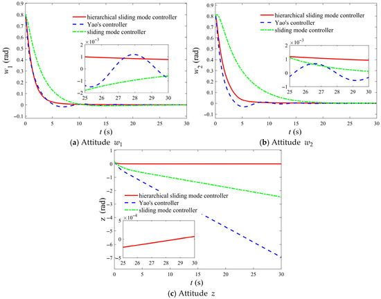
Figure 1.
Comparison of the control effects of different control laws on the attitude parameters of underactuated spacecraft under small initial attitude conditions.
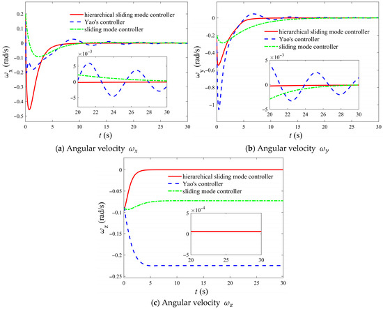
Figure 2.
Comparison of the control effects of different control laws on the angular velocity of underactuated spacecraft under small initial attitude conditions.
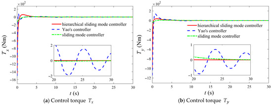
Figure 3.
Comparison of drive axis control torque under different control laws under small initial attitude conditions.
It can be observed from Figure 1 and Figure 2 that for the controller proposed in this paper, the angular velocity and attitude of the underactuated spacecraft, including the underactuated axis, converge to the stable point 0 approximately at 7 s, and the convergence process is relatively smooth, which differs from the buffeting phenomenon of general sliding mode control. Meanwhile, there exists a phenomenon that angular velocity and attitude of the underactuated axis always converge to the stable point prior to the other two axes, which reflects the hierarchical terminal sliding mode control concept designed in this paper, namely an appropriate control quantity is always selected to ensure that the sliding variable where the underactuated axis is located converges to zero first. At this point, the controller transforms into a degenerate controller that does not incorporate the angular speed and attitude of the underactuated axis, causing the system to exhibit a fully actuated state.
Compared to the control law proposed by Yao and the general sliding mode control law, the control law introduced in this paper demonstrates superior advantages. Figure 1, Figure 2 and Figure 3 also illustrates the control performance of Yao’s designed control law and the general sliding mode control law on the attitude and angular velocity. First, Yao’s controller and the general sliding mode control law are consistent with traditional controllers in that it requires an initial angular velocity of zero. In contrast, the controller proposed in this paper does not require a zero initial angular velocity, thus offering broader applicability. Furthermore, the precision of Yao’s control law and the general sliding mode control law are lower than that of the hierarchical sliding mode control law developed in this study. Specifically, the proposed method in this paper enables the angular velocity to converge with a precision of , whereas Yao’s method achieves only . Additionally, this controller secures an attitude convergence accuracy of , a significant improvement in the precision attainable with Yao’s controller. Meanwhile, the hierarchical sliding mode control law stabilizes the attitude in approximately 7 s, the control law of Yao stabilizes in approximately 10 s, while the general sliding mode control law stabilizes in close to 20 s, demonstrating the rapidity of the control law designed in this paper. Compared with the control law of Yao, the hierarchical sliding mode control law did not show an overshoot phenomenon. A comparison of the attitude and angular velocity along the underactuated axis for the three controllers further emphasizes these distinctions. The specific comparison of control performance is presented in Table 1.

Table 1.
Comparison of control effects under different control laws.
The calculation of energy consumption is quantitatively evaluated through a proxy index method. The proxy index is the total control action, that is, the integral of the absolute value of the control torque over time, which directly represents the fuel consumption. Mathematically, it is expressed as
The control law introduced by Yao and the general sliding mode control law do not ensure convergence of both the attitude and angular velocity to a stable point of zero but instead approach a constant value. In contrast, the hierarchical terminal sliding mode control law proposed here achieves convergence of both the attitude and angular velocity along the underactuated axis to a stable point of zero, ultimately reaching a stable configuration.
Furthermore, as demonstrated in Figure 3, the controller proposed by Yao, the general sliding mode control law, and the hierarchical sliding mode controller introduced in this paper are capable of rapidly and smoothly driving the control torque to zero. However, the hierarchical sliding mode controller presented in this study requires a smaller control torque, thereby providing enhanced applicability. The smaller control torque also means less energy is consumed, making it more suitable for engineering applications. The specific fuel consumption comparison is shown in Table 1. In addition, the hierarchical sliding mode control law proposed in this paper does not exhibit oscillation phenomena near the stable point, which is not possessed by Yao’s control law. Although general sliding mode control law does not show detailed oscillation either, its convergence rate is much lower than that of the hierarchical sliding mode control law.
To further verify the universality of the control law designed in this paper, a set of other small initial states were selected for simulation. The initial attitude is set to and the initial angular velocity is set to . The results are shown in Figure 4.
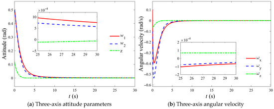
Figure 4.
Verification of the universality of control laws in small initial states.
5.2. Large Initial Attitude Simulation
In contrast to previous studies on the attitude control of underactuated spacecrafts, the control law proposed in this paper demonstrates effective performance even with a larger initial attitude. The large initial attitude is set to . The controller parameters used in this simulation are largely consistent with those employed in a condition of a small initial attitude. However, to ensure non-singularity of the controller, the singularity avoidance parameter needs to be adjusted. In this simulation, . To demonstrate the robustness of the designed control law against external disturbances, the external disturbance is set as , and .
The simulation is also compared with Yao’s control law and the general sliding mode control law, and the specific simulation results are shown in Figure 5, Figure 6 and Figure 7. The results show that, including the underactuated axis, the spacecraft’s three-axis attitude successfully converges to zero with an accuracy of . Simultaneously, the angular velocity across all three axes also converge rapidly to zero, achieving a precision of . Under conditions of large initial attitudes and identical disturbances, the controller developed in this study demonstrates advantages over the controller proposed by Yao across multiple dimensions. First, regarding robustness, the convergence accuracy of both attitude and angular velocity is significantly higher than that achieved by Yao’s controller and the general sliding mode control law, with improved disturbance rejection capabilities. In terms of convergence speed, both the hierarchical sliding mode control law and the Yao control law converge at around 6 s, which is far ahead of the 15 s of the general sliding mode control. However, in terms of overshoot, the hierarchical sliding mode control law does not have an overshoot, which is superior to the small overshoot of the Yao control law. The specific comparison of control performance is presented in Table 2. Additionally, the proposed controller ensures that the angular velocity and attitude of the underactuated axis converge to zero, whereas Yao’s controller and the general sliding mode control law only enables convergence to a constant value.
Figure 5.
Comparison of the control effects of different control laws on the attitude parameters of underactuated spacecraft under large initial attitude conditions.
Figure 6.
Comparison of the control effects of different control laws on the angular velocity of underactuated spacecraft under small initial attitude conditions.
Figure 7.
Comparison of drive axis control torque under different control laws under small initial attitude conditions.
Table 2.
Comparison of control effects under different control laws.
Furthermore, under the same disturbance, while the final control torques generated by the three controllers tend to the same level, the initial control torque required by Yao’s controller and the general sliding mode control controller is substantially higher, demanding greater energy consumption, which may limit its practicality in engineering applications. The specific fuel consumption comparison is shown in Table 2.
The convergence behavior remains largely consistent under larger initial attitude and smaller initial attitude conditions. The angular velocity and attitude stabilize and smoothly converge to zero, though the convergence process differs slightly, with the convergence accuracy being marginally lower for larger initial attitudes. Additionally, it is noticeable that the convergence speed of the underactuated axis decreases, which is attributed to the finite-time convergence nature of the control law, inherently linking the convergence time to the initial values of the angular velocity and attitude of the underactuated spacecraft. Furthermore, in contrast to the condition with smaller initial attitudes, the control torque for larger initial attitudes exhibit fluctuations, reflecting a more complex dynamic behavior than that observed in the smaller initial attitude case.
To further verify the universality of the control law designed in this paper, another set of large initial states was selected for simulation. The initial attitude is set to and the initial angular velocity is set to . In addition, to better align with the actual situation, considering the aforementioned external interference torque, Gaussian white noise interference and sensor measurement noise were added. The noise parameters were set at the
level. The results are shown in Figure 8.
Figure 8.
Verification of the universality of control laws in large initial states.
6. Conclusions
This paper investigates the attitude control problem of an underactuated spacecraft equipped with thrusters in only two directions. To achieve tri-axis stabilization of underactuated spacecraft, a kinematic model using w-z parameters was employed, and a hierarchical sliding mode control law was proposed. The global finite-time stability of the sliding variables was proven using the Lyapunov stability theorem and finite-time convergence theory. Finally, numerical simulations validated the effectiveness and correctness of the proposed control law, demonstrating that the angular velocity and attitude (including the underactuated axis) can converge rapidly and stably to the equilibrium point, regardless of whether the initial attitude is large or small, thus addressing the shortcomings in controlling the underactuated axis. Notably, the core concept of the hierarchical terminal sliding mode control framework introduced in this work—sequentially addressing underactuated constraints and achieving finite-time stability through the construction of multi-layer sliding mode surfaces—is inherently generalizable. This approach is expected to be extendable to other actuator types, such as reaction wheels (RWs) and control moment gyroscopes (CMGs). Furthermore, the proposed control structure, particularly the design principle of the hierarchical sliding mode surface, can be directly adapted to the controller design of similar systems by incorporating appropriate actuator models.
Another challenge in the attitude control system of underactuated spacecraft is robustness. Given the underactuated spacecraft’s limited ability to cope with external disturbances, inertia uncertainties, and flexible appendages, a sliding mode control method integrated with an adaptive approach to adjust system parameters is used to address issues of disturbances and uncertainties. Furthermore, considering the hierarchical structure of the system model, a regression control method is proposed to enhance the robustness of the attitude control system for underactuated spacecrafts. This approach will require further development and refinement in future work.
Author Contributions
Conceptualization, J.W.; methodology, J.W.; software, W.L.; validation, H.H.; formal analysis, J.W.; investigation, J.W.; resources, W.L.; data curation, W.L.; writing—original draft preparation, J.W.; writing—review and editing, B.Z.; visualization, H.H.; funding acquisition, H.H. All authors have read and agreed to the published version of the manuscript.
Funding
This research was funded by the Guangdong Basic and Applied Basic Research Foundation under grant2023A1515011582, the National Natural Science Foundation of China under grant 62003268.
Data Availability Statement
The data that support the findings of this study are available on request from the second author, Wenhao Lyu, upon reasonable request.
Conflicts of Interest
The authors declare no conflicts of interest. The funders had no role in the design of the study; in the collection, analyses, or interpretation of data; in the writing of the manuscript; or in the decision to publish the results.
References
- Jin, L.; Li, Y. Model Predictive Control-Based Attitude Control of Under-Actuated Spacecraft Using Solar Radiation Pressure. Aerospace 2022, 9, 498. [Google Scholar] [CrossRef]
- Zhang, Y.; Chen, K.; Guo, J.; Wei, C. Dynamics and Staged Deployment Strategy for a Spinning Tethered Satellite System. Aerospace 2025, 12, 611. [Google Scholar] [CrossRef]
- Liu, Z.; Chen, G.; Xu, S. Modeling and Control of Reconfigurable Quadrotors Based on Model Reference Adaptive Control. Aerospace 2024, 11, 687. [Google Scholar] [CrossRef]
- Crouch, P. Spacecraft attitude control and stabilization: Applications of geometric control theory to rigid body models. IEEE Trans. Automat. Contr. 1984, 29, 321–331. [Google Scholar] [CrossRef]
- Byrnes, C.I.; Isidori, A. On the attitude stabilization of rigid spacecraft. Automatica 1991, 27, 87–95. [Google Scholar] [CrossRef]
- Brockett, R.W. Asymptotic stability and feedback stabilization. Differ. Geom. Control. Theory 1983, 27, 181–191. [Google Scholar] [CrossRef]
- Zhang, K.K.; Zhou, B.; Jiang, H.; Duan, G.R. Finite-time control of a class of nonlinear underactuated systems with application to underactuated axisymmetric spacecraft. IEEE Trans. Aerosp. Electron. Syst. 2023, 59, 7061–7071. [Google Scholar] [CrossRef]
- Lu, J.; Meng, Z. Underactuated attitude-orbit coupling control for micro-satellite based on a single orbital thruster. IEEE Trans. Aerosp. Electron. Syst. 2024, 60, 2082–2092. [Google Scholar] [CrossRef]
- Nadafi, R.; Kabganian, M. Robust backstepping attitude tracking control of an underactuated spacecraft with saturation and time-variant perturbations. Proc. Inst. Mech. Eng. Part G-J. Aerosp. 2022, 236, 502–516. [Google Scholar] [CrossRef]
- Brewer, J.M.; Tsiotras, P. Exponential stabilization of the complete attitude of an underactuated spacecraft. In Proceedings of the 2022 American Control Conference (ACC), Atlanta, GA, USA, 8–10 June 2022. [Google Scholar] [CrossRef]
- Hao, J.H.; Zhang, P.F.; Ma, D.Y.; Zhang, Y.H.; Hong, F. Underactuated attitude reorientation method based on a novel decoupled characteristic of the plane-axis rotation. Aerosp. Sci. Technol. 2021, 119, 107189. [Google Scholar] [CrossRef]
- Nadafi, R.; Kabganian, M. Robust nonlinear attitude tracking control of an underactuated spacecraft under saturation and time-varying uncertainties. Eur. J. Control 2022, 63, 133–142. [Google Scholar] [CrossRef]
- Zou, A.M.; Kumar, K.D.; Ruiter, A.H. Spacecraft attitude control using two control torques. Inf. Sci. 2017, 408, 23–40. [Google Scholar] [CrossRef]
- Tian, H.; Li, A.; Wang, Y.; Wang, C.Q. Underactuated attitude tracking control of tethered spacecraft for deployment and spin-up. Adv. Space. Res. 2023, 71, 4829–4842. [Google Scholar] [CrossRef]
- Meng, Z.J.; Lu, J.J. Fuzzy gain-adapting coupling attitude control for under-actuated spacecraft. Chin. Space Sci. Technol. 2024, 44, 11–19. Available online: https://journal26.magtechjournal.com/kjkxjs/CN/10.16708/j.cnki.1000-758X.2024.0053 (accessed on 13 October 2025).
- Zhou, B.; Zhang, K.K. Smooth Time-Varying Feedback Control of Nonholonomic Systems with Applications to the Attitude Control of Underactuated Spacecraft. Guid. Navig. Control. 2024, 4, 2450004. [Google Scholar] [CrossRef]
- Wang, L.X. Analysis and design of hierarchical fuzzy systems. IEEE Trans. Fuzzy. Syst. 1999, 7, 617–624. [Google Scholar] [CrossRef]
- Hwang, C.L.; Yang, C.C.; Hung, J.Y. Path tracking of an autonomous ground vehicle with different payloads by hierarchical improved fuzzy dynamic sliding-mode control. IEEE Trans. Fuzzy. Syst. 2017, 26, 899–914. [Google Scholar] [CrossRef]
- Avanzini, G.; Zavoli, A.; De Matteis, G.; Giulietti, F. Single axis pointing for underactuated spacecraft with a residual angular momentum. Aerosp. Sci. Technol. 2022, 124, 107512. [Google Scholar] [CrossRef]
- Bai, Y.; Wu, Y.Y.; Wen, J. Attitude Stabilization Control for Underactuated Spacecraft: A Predefined-Time Method. Space: Sci. Technol. 2025, 5, 0272. [Google Scholar] [CrossRef]
- Yao, Q.; Li, Q.; Jahanshahi, H. Convergence guaranteed attitude control of underactuated spacecraft using two control torques. Adv. Space. Res. 2024, 73, 2663–2673. [Google Scholar] [CrossRef]
- Surganova, Y.E.; Mikhlin, Y.V. Stability of nonlinear normal modes in the system of coupled pendulums in a magnetic field. Int. J. Non Linear Mech. 2024, 160, 104649. [Google Scholar] [CrossRef]
- Dao, P.N.; Phung, M.H. Nonlinear robust integral based actor–critic reinforcement learning control for a perturbed three-wheeled mobile robot with mecanum wheels. Comput. Electr. Eng. 2025, 121, 109870. [Google Scholar] [CrossRef]
- Ismail, Z.; Varatharajoo, R.; Chak, Y.C. A fractional-order sliding mode control for nominal and underactuated satellite attitude controls. Adv. Space. Res. 2020, 66, 321–334. [Google Scholar] [CrossRef]
- Duan, C.; Shao, X.D.; Hu, Q.L. Attitude tracking of underactuated spacecraft based on transverse function. Acta. Aeronaut. Astronaut. Sin. 2024, 45, 628910. Available online: https://hkxb.buaa.edu.cn/EN/10.7527/S1000-6893.2024.28910 (accessed on 13 October 2025).
- Zhang, Z.; Hao, Y.A.; Jiang, B. Fault tolerant attitude control of under-actuated spacecraft: Theory and experiment. Chin. J. Aeronaut. 2023, 36, 465–474. [Google Scholar] [CrossRef]
- Alger, M.; Ruiter, A. Practical considerations using transverse function methods on underactuated reaction wheel controlled spacecraft. Acta Astronaut. 2025, 228, 101–120. [Google Scholar] [CrossRef]
- Ousaloo, H.S. Globally asymptotic three-axis attitude control for a two-wheeled small satellite. Acta Astronautica 2019, 157, 17–28. [Google Scholar] [CrossRef]
- Jia, S.; Qiu, J.; Wang, T. High-Order Fully Actuated System Approach-Based Attitude Stabilization for Underactuated Rigid and Flexible Spacecraft. IEEE Trans. Autom. Sci. Eng. 2025, 22, 15094–15105. [Google Scholar] [CrossRef]
- Golzari, A.; Pishkenari, H.N.; Salarieh, H.; Abdollahi, T. Quaternion based linear time-varying model predictive attitude control for satellites with two reaction wheels. Aerosp. Sci. Technol. 2020, 98, 105677. [Google Scholar] [CrossRef]
- Bunryo, Y.; Satoh, S.; Shoji, Y.; Yamada, K. Feedback attitude control of spacecraft using two single gimbal control moment gyros. Adv. Space. Res. 2021, 68, 2713–2726. [Google Scholar] [CrossRef]
- Celani, F.; Heydari, M.; Novinzadeh, A.B. Model-Free Adaptive Control for Attitude Stabilization of Earth-Pointing Spacecraft Using Magnetorquers. Aerospace 2025, 12, 219. [Google Scholar] [CrossRef]
- Tsiotras, P.; Longuski, J.M. A new parameterization of the attitude kinematics. J. Astronaut. Sci. 1995, 43, 243–262. [Google Scholar]
- Filippov, A.G. Application of the theory of differential equations with discontinuous right-hand sides to non-linear problems in automatic control. In Proceedings of the 1st IFAC Congress, Butterworths, London, 30 September–2 October 1961. [Google Scholar] [CrossRef]
- Chen, T.; He, X.; Lou, Y.; Liu, H.; Liang, L.; Zhang, K. Fuzzy-Adaptive Nonsingular Terminal Sliding Mode Control for the High-Speed Aircraft Actuator Trajectory Tracking. Aerospace 2025, 12, 578. [Google Scholar] [CrossRef]
- Ai, H.; Jiang, L.; Zhu, A.; Fu, X. Adaptive Neural Network-Based Fixed-Time Trajectory Tracking Control of Space Robot with Uncertainties and Input Nonlinearities. Aerospace 2025, 12, 593. [Google Scholar] [CrossRef]
Disclaimer/Publisher’s Note: The statements, opinions and data contained in all publications are solely those of the individual author(s) and contributor(s) and not of MDPI and/or the editor(s). MDPI and/or the editor(s) disclaim responsibility for any injury to people or property resulting from any ideas, methods, instructions or products referred to in the content. |
© 2025 by the authors. Licensee MDPI, Basel, Switzerland. This article is an open access article distributed under the terms and conditions of the Creative Commons Attribution (CC BY) license (https://creativecommons.org/licenses/by/4.0/).