Abstract
The air turbine starter (ATS) of an aero-engine incorporates a high-speed, high-energy rotor. An uncontained failure of the ATS could lead to catastrophic consequences, making containment capability research critically important. This study proposes a comprehensive evaluation methodology for ATS containment. A full-scale finite element model of the whole structure of an ATS was established to analyze containment characteristics and structural deformation patterns. Furthermore, an experimental method for ATS containment testing was designed to investigate the containment process and critical structural damage. By integrating simulation and experimental results, the load transfer paths and structural dynamic response of the ATS were systematically analyzed. The results demonstrate that sudden high-energy loads primarily follow two distinct transfer paths, each causing completely different structural damage behaviors. After the turbine wheel is broken, the resulting unbalanced load causes turbine shaft oscillation, which, in turn, compresses the bearings and damages their inner and outer rings. This research provides valuable guidance for the structural design of air turbine starters.
1. Introduction
To initiate the operation of gas turbine engines, an apparatus called an air turbine starter (ATS) is employed. The air turbine starter is designed to provide substantial starting torque by utilizing a small and lightweight power source. The start system must produce a sufficient amount of torque and speed for the turbine rotor and must be sufficiently light and small, which poses a challenge for the containment of the starter [1]. Typically, more uncontained failures and accidents occur on turbine engines. Uncontained engine failures can produce high-speed pieces that may impact and damage the surrounding structures and equipment. In August 1985, a Boeing 737 suffered an uncontained failure of the left engine, and a fuel tank access panel on the lower surface of the left wing was punctured, causing a large hole in the main fuel tank [2]. In 2010, uncontained engine failures occurred in two high-capacity aircraft (a Boeing 747 and an Airbus A380), significantly threatening flight safety [3]. Uncontained failures in the ATS have also occurred. In October 2007, an uncontained failure of the starter turbine of an Airbus A330-300 damaged the integrated drive generator and rendered the starter unable to start [4]. In October 2013, the ATS of an A330-302 aircraft sustained an uncontained failure, and pieces of the starter turbine wheel severed the oil sump scavenging pipe, resulting in one engine shutting down because of the lack of oil [5]. Therefore, realizing the containment of the turbine wheels is an important measure for ensuring flight safety.
The airworthiness standards of transport category airplanes in the United States (FAR 25.1461) [6] and China (CCAR 25.1461) [7] stipulate that equipment containing high-energy rotors must be able to contain any failure of a rapidly spinning rotor with high energy; i.e., sufficient containment capacity is required [8]. Therefore, researchers have begun to study the containment of some high-rotation machines and structures.
Xuan [9] adopted a combination of experimental and numerical methods to study the containment process and principles under different parameter combinations of the blade length and release speed; they determined that failure of the containment rings caused by the second impact should be given greater attention. Gálvez [10] researched the behaviors of metallic materials for jet engine turbine containment under high strain rates and high temperatures; the Johnson–Cook material model was used to fit the experimental results. In 2008, Teng [11] posed a numerical model and prediction method for the failure response of an aircraft engine containment panel obliquely impacted by a titanium turbine piece. In 2009, Stahlecker [12] developed and verified a constitutive model for dry fabrics that was used as a subroutine in LS-DYNA; this model was then used to simulate a suite of ballistic tests whose conditions were similar to an engine fan blade out (FBO) event. Sinha [13] numerically analyzed a typical FBO event and presented the results for the primary and secondary damage of an LS-DYNA simulation of this event using a full-engine model. In 2013, Yang [14] implemented a margin of safety (MS) analysis and presented fan blade-off experimental results of the PX8 engine model for engine airworthiness certification, thus providing a useful guideline for evaluating engine containment capability. In 2016, Bai [15] experimentally and numerically evaluated the ability of U-type ring containment to resist three rotor wheel pieces, demonstrating that a containment ring with an appropriate U structure has a strong containment capability. This study also provided a method for designing the groove depth of the containment ring. Kesare [16] used an explicit ANSYS AUTODYNA technique and a finite element model to numerically investigate the containment phenomena and characteristics of a turbine wheel burst. He [17] studied the containment of an engine casing for a multi-blade fan and turbine using simulations and experiments. Multi-blade effects were found making it easier for the released blade to penetrate the fan and turbine. In 2018, Buchroithner [18] developed a low-cost test rig to study the containment of high-speed rotating machines with different rotor failure modes, thereby assessing the containment capability of various machines with wheel bursts.
In 2019, Sawaikar [19] summarized the current research status of containment testing and simulations, introduced some methods used to achieve impeller bursts at target speeds, and discussed methodologies to make the simulations more accurate. Wang [20] researched the impact responses of 2618 aluminum for engine containment systems at high velocity through tests and simulations; the J-C model was used in the simulations to acquire the target responses and characteristics of the damage. Eryilmaz [21] numerically investigated the effects of multi-blade shedding in the high-pressure turbine of a large civil engine using LS-DYNA and proposed the containment requirements for multi-blade shedding in the situation of wheel burst. In 2021, He [22] numerically investigated the containment capability of four stainless steel casings (with different thicknesses) for alloy axial compressor blades; the calculation results agreed well with the experimental results. In 2023, Sepúlveda [23] developed a finite element numerical analysis method for turbine fan engine blade containment using the J-C model and analyzed the structural integrity of the Ti-6Al-4V casing after impact by a fan blade of the same material. However, these studies focused more on the containment issues of aircraft engines, and research on wheel and blade containment has mainly been conducted through component-level experiments; only a few studies have introduced numerical simulations of the whole engine structure under blade loss. Most importantly, few studies have been conducted on the containment issues of ATSs.
An ATS is a type of gas turbine starter; therefore, preventing the ATS from suffering containment failure is important because it can lead to severe damage to the engine or aircraft [24]. In 1984, Giard [25] studied the relationship between the number of turbine wheel pieces and their translational energy based on an ATS and concluded that a trisection wheel burst led to the highest translational energy of the wheel pieces. In 2010, Biswas [26] analyzed the principle of ATS failure, indicating that when a few blades of the turbine rotor wheel failed, the remaining blades failed under sudden overload, and crack initiation appeared at the blade root. In 2023, Chen [27] proposed a neck structure for an optimal turbine wheel design method using optimization algorithms; the method was verified based on experimental and simulation results. A rim burst could dramatically decrease the mass and initial kinetic energy of the pieces compared with a trisection wheel burst. Zhang [8] introduced an optimal design method for a U-type containment ring by combining simulations and genetic algorithms to enhance energy absorption and reduce weight. The results exhibited an improved containment performance and a significant weight reduction. However, all of these studies focused primarily on containment of the ATS on the component level. To date, few researchers have studied the containment of the whole ATS structure, thus neglecting the impact of the real boundary conditions of the containment problem. At the same time, the influence of the load transmission path of the overall machine structure on containment has also been ignored, and the influence mechanism of different load transfer paths on structural damage could not be clearly defined.
In summary, current domestic and international methods for evaluating the structural safety of Air Turbine Starters (ATS) primarily focus on localized components. However, due to the structural complexity of ATS, sudden high-energy loads impact not only the containment ring but also the entire turbine shaft system and planetary gear structure. Consequently, safety assessments that only consider partial ATS structures have inherent limitations. To address this limitation, this study proposes a comprehensive containment analysis method based on the full ATS structure. First, a finite element model (FEM) of the entire ATS structure was developed to assess its deformation characteristics and damage behavior. Subsequently, an aerodynamic test platform for the full ATS structure was established, and structural deformation and damage patterns at critical locations were used to validate the FEM. By integrating simulation and experimental results, this study further clarifies the transmission mechanisms and dynamic response characteristics of sudden high-energy loads. Ultimately, this research provides valuable technical references for both the structural design and safety evaluation of ATS.
2. ATS Containment Simulation
A simulation analysis method for ATS containment was proposed, and the containment process and critical structural damage were analyzed using the proposed method.
2.1. ATS Structure
Figure 1 shows the structure of the ATS. The high-pressure gas from the intake pipe drives the turbine wheel to rotate at high speed, and the turbine shaft drives the output shaft to rotate through a planetary gear set. The output shaft drives the aero-engine through the accessory gearbox. In the actual use state, in front of the intake casing, a high-pressure gas pipe is connected to the intake casing through a clamp. At the other end of the starter, the flange of the decelerator casing is connected to the outer wall of the engine accessory gearbox using a clamp. The output shaft is connected to the drive shaft in the accessory gearbox by the spine.
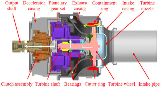
Figure 1.
ATS structure.
Turbine wheels break in service because of material fatigue. Therefore, a containment ring is installed on the outside of the turbine wheel to contain the wheel-burst pieces. The energy of a wheel piece can be absorbed through containment ring deformation, which is the key to realizing ATS containment.
The large unbalanced load caused by turbine wheel bursts causes turbine shaft bending, bearing damage, and planetary gear damage. The intake, exhaust, and decelerator casings are connected using bolts. During the wheel-burst process, some of the fragments collide directly with the external casings to create an impact load. In addition, part of the internal impact load is transferred to the casings through the shaft and planetary gears. Thus, the ATS will experience significant impact vibrations. Consequently, these can easily cause failure of the connection structure of the starter.
2.2. Finite Element Model and Boundary Conditions
The finite element models of the rotating components, including the turbine wheel, turbine shaft, bearings, planetary gear, and output shaft, are shown in Figure 2. The tangential translational energy is at its maximum when the turbine wheel is broken into three equal pieces, [7] and a containment simulation of the trisection wheel burst is conducted. Therefore, a finite element model of the turbine wheel with three equal pieces is established. For the turbine wheel, the blades and wheel are meshed using tetrahedral and hexahedral elements, respectively. The turbine shaft is then meshed using tetrahedral elements. The contact surface between the wheel and shaft has a common-node connection. In the rotor modeling process, in addition to the turbine rotor and shaft, support bearings and planetary gears were also included. By incorporating these complete shaft system components, the simulation more accurately captures the effects of high-energy load transmission on the shaft components during the turbine wheel burst [28]. Therefore, a finite element model of the bearing is established using a multi-body bearing model. The ball is meshed using tetrahedral elements, and the inner and outer rings are both meshed using hexahedral elements. The planetary gear and output shaft are meshed using tetrahedral and hexahedral elements, respectively [22,29].
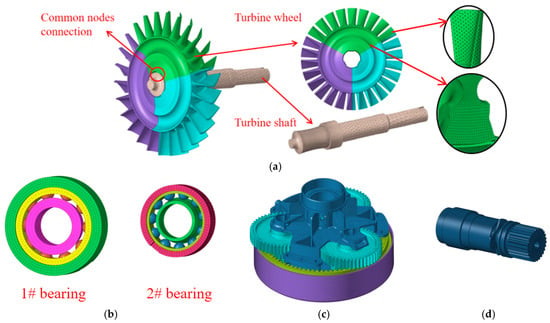
Figure 2.
Finite element models of rotating components: (a) turbine rotor; (b) bearings; (c) planetary gear; (d) output shaft.
The finite element models of the containment components are shown in Figure 3, including the containment ring, intake casing, exhaust casing, and decelerator casing. To simulate the containment process more effectively, at least two mesh layers are established in the thickness direction of the containment component. The containment ring is meshed using hexahedral elements, and four mesh layers are established in the thickness direction. The intake and decelerator casings are meshed with tetrahedral elements. The extending inner wall of the exhaust casing is an important structure for withstanding the impact load of the wheel, and, thus, the inner wall of the exhaust casing is meshed using hexahedral elements, whereas the remainder of the exhaust casing is meshed using tetrahedral elements.
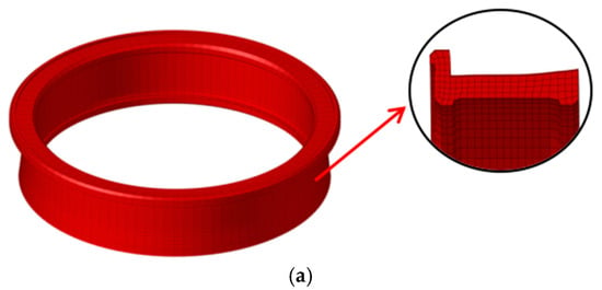

Figure 3.
Finite element models of containment components: (a) containment ring; (b) intake casing; (c) exhaust casing; (d) decelerator casing.
The finite element model of the entire ATS is shown in Figure 4; the number of elements is 1,741,112. In an actual installation, the intake casing is connected to the rigid air intake pipe by a clamp; therefore, an axial displacement constraint is applied to the flange of the intake casing. The decelerator casing is connected to the aero-engine accessory gearbox by a clamp; therefore, a fixed constraint is applied to the flange of the decelerator casing. The intake, exhaust, and decelerator casings are connected using nine long bolts. A solid model of the bolt is adopted because this model can fully reflect the bolt deformation and the interaction between the bolt and hole [30]. An automatic single-surface contact is defined between the bolt cylinder surface and the bolt hole. A free boundary is adopted for the containment ring. An automatic single-surface contact and global eroding contact is defined for the contact components. The dynamic process time for the impact calculated by the simulation is set to 2 ms, which is sufficient to capture the complete process of impact following the burst of the turbine wheel [8].
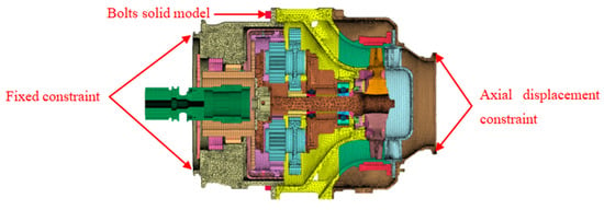
Figure 4.
Finite element model of the whole ATS.
For a certain type of ATS, the working speed of the turbine is 60,000 r/min. According to the ATS containment design requirement, the experimental speed should be 1.2 times the working speed. Therefore, the turbine speed is set to 72,000 r/min for the simulation. In the ideal case, if the turbine wheel pieces fly off simultaneously, no unbalanced load is generated on the shaft; therefore, the shaft or its backup bearings will not be severely damaged. However, in the actual situation, the three wheel pieces cannot be ejected simultaneously. Transient analysis was conducted using 0.03 ms time steps, with staged wheel fragment release events triggered at consecutive step intervals (Δt = 0.03 ms), replicating the temporal progression of the wheel burst. Thus, three wheel pieces are ejected successively at 0.03, 0.06, and 0.09 ms, respectively.
2.3. Material Model
The Johnson–Cook model is selected as the material model for the contact components because it considers the effect of the strain rate on the material. The Johnson–Cook constitutive relation [31] is expressed as follows:
where A, B, C, n, and m are material constants; σe is the equivalent von Mises stress; is the equivalent plastic strain; is the dimensionless strain rate; and is the homologous temperature. The Johnson–Cook fracture criterion is based on damage evolution and is defined as follows:
where is the increment in the equivalent plastic strain that occurs during integration, and is the fracture strain. Failure is assumed to occur through element erosion when D equals unity.
There are five material parameters to be determined in the J-C failure model, namely, D1~D5, which need to be fitted and obtained through test data under different stress states, different strain rates and different temperature conditions.
Parameters D1, D2 and D3 in the J-C failure model mainly express the influence of the failure strain of the material base and the stress state on the failure strain. The stress state in the model is characterized by the triaxial stress, which is a dimensionless parameter reflecting the degree of triaxial stress at a certain point within the material. The triaxial stress of notched specimens can be approximately calculated by the Bridgman empirical equation [32]:
In the equation, is the initial diameter of the notch section, and is the initial radius of the notch.
Under the reference strain rate () and reference temperature (), the J-C failure model can be expressed as:
From the above Equation (4), the failure strain of the material was measured at room temperature and under different stress triaxial conditions. Then, by drawing the relationship curve between the failure strain and the triaxial stress, the values of parameters D1, D2 and D3 can be fitted.
Parameter D4 expresses the influence of strain rate on failure strain in the J-C failure model. At the reference temperature, the J-C failure model of the material can be expressed as:
When D1, D2 and D3 are known, the value of D4 can be fitted by the relationship curves of the failure strain and logarithmic strain rate of the material at room temperature, the same stress state and different strain rates.
Parameter D5 expresses the influence of temperature on failure strain in the J-C failure model. Under the reference strain rate, the J-C failure model of the material can be expressed as:
When D1, D2 and D3 are known, the failure strain of the material under the same stress state and different temperatures can be measured. By fitting the relationship curve between the failure strain and temperature, D5 can be obtained.
The J-C model parameters for the contact components used in the calculations are listed in Table 1. Partial material parameters were referenced from the relevant literature, while the remaining parameters were obtained from prior experimental data in the laboratory.

Table 1.
J-C model material parameters for the contact components [27,33,34,35].
2.4. Containment Ability Analysis
2.4.1. Containment Process
The ATS containment process for the trisection turbine wheel burst is shown in Figure 5. As in the simulation, the first wheel piece begins to burst at t = 0.03 ms, after which it is ejected under centrifugal force. At t = 0.06 ms, the second wheel piece is ejected, and the extending inner wall of the exhaust casing is impacted by the first wheel piece and severely deformed, while the turbine shaft head tends to sway under the unbalanced load. At t = 0.15 ms, the inner wall of the exhaust casing breaks under the impact of the wheel pieces, the turbine wheel pieces first impact the containment ring, and the turbine shaft head is bent significantly. Simultaneously, the turbine wheel piece breaks the cutter ring. Notably, the flight trajectory of the turbine wheel piece has changed somewhat. The inner ring of the bearing on the turbine shaft near the turbine wheel is damaged under the compression of the turbine shaft. At t = 0.3 ms, the wheel pieces continue to fly radially and break the inner wall of the exhaust casing. Subsequently, the wheel pieces further impact the containment ring, which is significantly deformed, and the blades in the wheel are broken. Simultaneously, under the compression of the turbine shaft, the inner ring of the bearing breaks, and both the bearing ball cage and the bearing outer ring are damaged to some extent. At t = 1.35 ms, the bending deformation of the shaft decreases, and the wheel pieces are stopped between the containment ring and turbine nozzle. Thus, the impact process is complete. The simulation is halted at t = 2 ms. The results show that in addition to the wheel damage, shaft bending, containment ring deformation, casing damage, bearing damage, and fracture damage also occur on the cutter ring and turbine nozzle under the impact load. The containment ring is not broken during the impact process, indicating that the containment ring structure has sufficient containment ability.
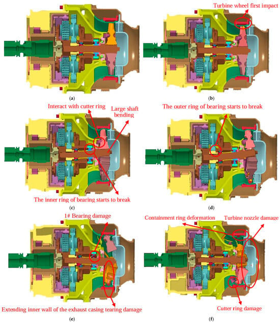
Figure 5.
ATS containment process. (a) t = 0.00 ms; (b) t = 0.06 ms; (c) t = 0.15 ms; (d) t = 0.30 ms; (e) t = 1.35 ms; (f) t = 2.00 ms.
2.4.2. Structural Deformation and Damage
The results within 0~1.35 ms representing the main impact process are selected to analyze the damage to key components. The damage and deformation processes of the containment ring during the simulation are shown in Figure 6. Figure 6 shows that at t = 0.03 ms, the turbine wheel begins to burst, and the turbine wheel pieces first impact the containment ring at t = 0.15 ms. During the entire impact process, the blades suffer severe bending or fracture damage; however, the containment ring is not broken. This implies that the containment ring has a sufficient containment ability.
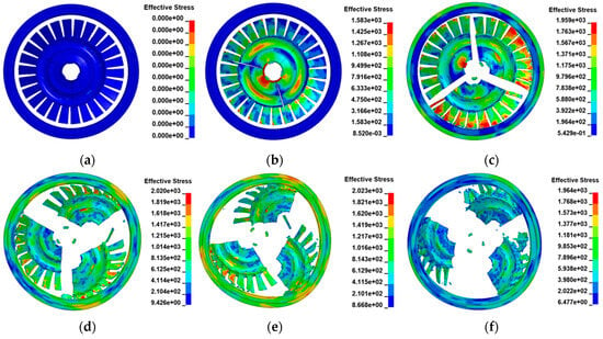
Figure 6.
Process of the turbine. Wheel pieces impacting the containment ring at t = (a) 0.00; (b) 0.03; (c) 0.15; (d) 0.30; (e) 0.42; and (f) 1.35 ms.
Figure 7 shows the various energy change processes of the turbine disk and the ring. As shown in the figure, the energy changes rapidly within t = 0 to 0.48 ms. After t = 0.48 ms, the energy of each component basically remained unchanged, and the shock process came to an end. In the numerical simulation, the kinetic energy of 1/3 turbine disk before and after impact was Ea = 23.6 kJ and Ek = 1.19 kJ, respectively, with a decrease of 94.96% in kinetic energy. The energy absorbed by the retaining ring is Ec = 22.41 kJ. Obviously, the vast majority of the kinetic energy of the wheel fragments is absorbed by the containment ring, thus achieving the containment effect.
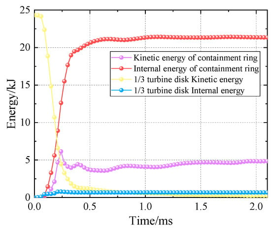
Figure 7.
Energy change and deformation in the containment process.
The damage and deformation processes of the shaft during the simulation are shown in Figure 8. Figure 8 shows that under the large unbalanced loads caused by the wheel burst, the shaft head sways, causing visible bending deformation of the turbine shaft. Simultaneously, the connecting surface between the turbine wheel and shaft is pulled by a large centrifugal load and is thereby broken to form a rough surface.
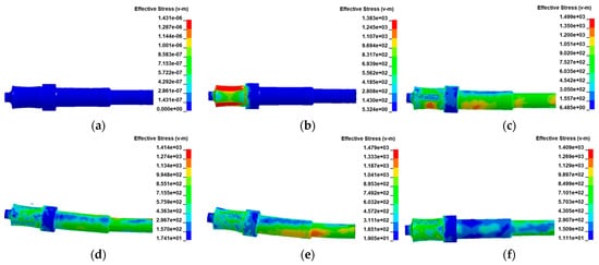
Figure 8.
Damage and deformation processes of the turbine shaft at t = (a) 0.00; (b) 0.03; (c) 0.15; (d) 0.30; (e) 0.42; and (f) 1.35 ms.
The damage and deformation processes of the bearing near the turbine wheel during the simulation are illustrated in Figure 8. Figure 9 shows that the bearing on the turbine shaft near the turbine wheel bears the main load during the containment process. First, the deformed turbine shaft compresses the inner ring of the bearing, which wears and breaks during impact with the balls. Subsequently, the retainer is broken under the pressure of the deformed turbine shaft and bearing balls. Finally, the outer ring of the bearing is severely damaged under the pressure of the deformed turbine shaft and bearing balls.
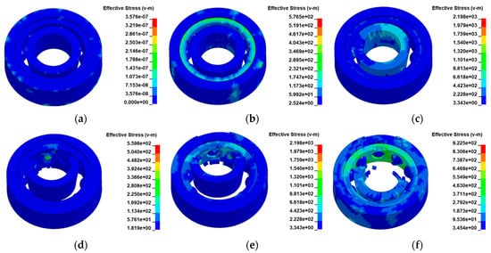
Figure 9.
Damage and deformation processes of the bearing near the turbine wheel at t = (a) 0.00; (b) 0.03; (c) 0.15; (d) 0.30; (e) 0.42; and (f) 1.35 ms.
3. ATS Containment Test
To investigate the ATS containment ability and vibration response of ATS casings, an ATS containment experiment was designed, and an ATS containment test platform was established. A turbine wheel cutting method was proposed to realize turbine wheel trisection bursts.
3.1. ATS Containment Experiment Design
The proposed ATS containment experimental design is as follows: First, a speed sensor is placed on the turbine shaft to obtain the wheel burst speed. Second, to capture the containment process, a trigger string is attached to the surface of the containment ring. Once the trigger string is cut by the impact of the wheel pieces, a high-speed camera automatically records the data. Third, a strain gauge layout scheme is proposed to obtain the containment ring response. Fourth, an acceleration sensor layout scheme is proposed to obtain the ATS casing vibration response. Finally, to observe the damage caused by flying pieces to the components near the ATS, an aluminum ring is designed around the ATS. It is worth attention that completed three turbine disk rupture tests to verify the accuracy of the cutting method before the ATS containment experiment, Detailed test methods are provided in the relevant references [8].
An ATS containment test platform is established based on the ATS containment experimental design, as shown in Figure 10. In accordance with the actual installation of the ATS on the aero-engine, the flange of the decelerator casing is connected to a mounting bracket through a clamp; the mounting bracket is connected to a mounting plate using bolts. The intake casing is connected to a high-pressure gas source pipe. To observe the damage caused by flying pieces to components near the ATS, an aluminum ring is installed around the ATS. On both the left and right sides of the intake pipe, two inspection windows are installed in the wall of the explosion-resistant enclosure, and two high-speed cameras are placed at the same horizontal height to obtain a full view of the enclosure. A total of six radial acceleration sensors are installed on the casings, which are arranged as follows: one sensor (#1) on the decelerator casing (located in section A-A), two sensors (#2 and #3) on the exhaust casing (located in section B-B), two sensors (#4 and #5) on the intake casing at the radial position corresponding to the containment ring (located in section C-C), and one sensor (#6) on the intake casing at the position of the inflow (located in section D-D). Using the axis of the bolt at the top of section A-A as the angular reference line, in the section where only one sensor is placed, the sensor is located at a phase angle of 30°, whereas in the section with two sensors, the sensors are located at phase angles of 30° and 120°.
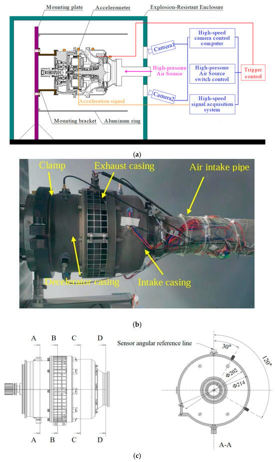
Figure 10.
ATS containment test platform: (a) schematic diagram; (b) installation photograph; (c) layout of the vibration measuring point positions.
3.2. Turbine Wheel Cutting Method
To cause a trisection turbine wheel burst at the designed speed, a turbine wheel cutting method is proposed. Radial and centrifugal slots are cut in the turbine wheel, as shown in Figure 11.
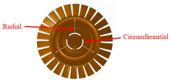
Figure 11.
Turbine wheel cutting method.
The force situation of a regular trisection wheel piece with a uniform cross-section is shown in Figure 12. The centrifugal load of the wheel piece is expressed as follows:
where σ1 is the average tensile stress on the circumferential joint surface A1 (mm2), and σ2 is the average tensile stress on the circumferential joint surface A2 (mm2). F1 can be obtained through integration as follows:
where r is the radius of the centrifugal slot, h is the wheel thickness, and θ is the angle (radians) of the circumferential load-bearing section. According to the average stress criterion, the wheel is assumed to burst when the average stresses on the radial and circumferential sections of the wheel simultaneously reach the ultimate strength, σb. Therefore, substituting Equation (7) into Equation (8), the force balance equation can be obtained as follows:
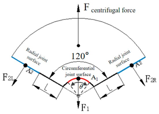
Figure 12.
Force diagram of the trisection wheel.
The centrifugal force of the wheel pieces can be expressed as
where M is the mass of the trisection wheel (g), Rc is the centroid radius (mm), and ω is the wheel speed (rad/s).
Combined with Equations (7) and (8), the relationship between the radical joint surface area and the circumferential slot angle θ can be obtained as follows:
According to the geometric relationship, the following geometric equation can be obtained:
Combining Equations (11) and (12), the relationship between the radial slot length, L(mm), and circumferential slot angle θ, can be obtained as follows:
where Rw is the radius of the turbine wheel. To break the turbine wheel simultaneously along the radial and circumferential directions, the stresses should be similar at the radial and circumferential slot edges. Combining the stress calculation and Equation (9) yields a circumferential slot angle θ = 90° and radial slot length L = 30.3 mm.
3.3. Containment Experimental Results
Figure 13 is the rotational speed versus time curve. Figure 12 shows that, initially at t = 0 ms, the airflow initiates turbine rotation, and the rotational speed increases rapidly under the power of the airflow. Between t = 0 and 0.95 ms, the turbine speed increases rapidly to 68,500 r/min. Subsequently, the speed increases slowly between t = 0.95 and 4.74 ms until it reaches the wheel-burst value (72,800 r/min), at which point the wheel bursts, and the wheel pieces impact the containment ring and cut off the trigger wire, sending a signal to the control system to halt the airflow. In this process, oscillations occurred due to the airflow driving the turbine. Between t = 4.74 and 5.30 ms, the speed rapidly drops to 0 r/min, and the turbine shaft stops rotating. Figure 12 also shows that the error between the experimental speed (72,800 r/min) and the design speed (72,000 r/min) is 1.1%, confirming the validity of the turbine wheel cutting method.
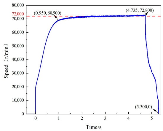
Figure 13.
Rotational speed versus time curve.
Notably, although the total time from the initiation of turbine rotation by the airflow to the stopping of the turbine shaft is 5.3 ms, the entire impact damage process of the air turbine starter persists for 2 ms, which can be verified by the simulation calculations.
After the burst of the turbine wheel, the pieces and sparks generated by the impact on the containment ring, turbine nozzle, intake casing, and aluminum ring overflow from the exhaust port, as shown in Figure 14. Figure 14 shows that as the turbine wheel first starts to burst, weak sparks appear owing to the impact. Subsequently, a large number of sparks appear, and some pieces are ejected instantly, indicating that the turbine wheel pieces have already begun to impact the containment ring. Next, numerous pieces impact the aluminum ring, generating large amounts of sparks. Finally, the number of sparks gradually decreases, and a large amount of dust is generated. At this point, the impact process is complete, and the aluminum ring is not broken. Based on the sequence of sparks generated at the different circumferential angles, the three turbine wheel pieces can be inferred to be ejected at different times. Therefore, setting different ejection times for the turbine wheel pieces in the simulation is reasonable.

Figure 14.
High-speed camera recordings of the containment process: (a) turbine wheel burst; (b) turbine wheel pieces impact the containment ring; (c) turbine wheel pieces impact the aluminum ring; (d) sparks decrease and dust appears.
Figure 15 is the damage to the turbine wheel after removing the air intake pipe. Figure 15 shows that the turbine wheel bursts into three pieces, and the blades in the turbine wheel are broken. Notably, all of the pieces are located in the ATS.
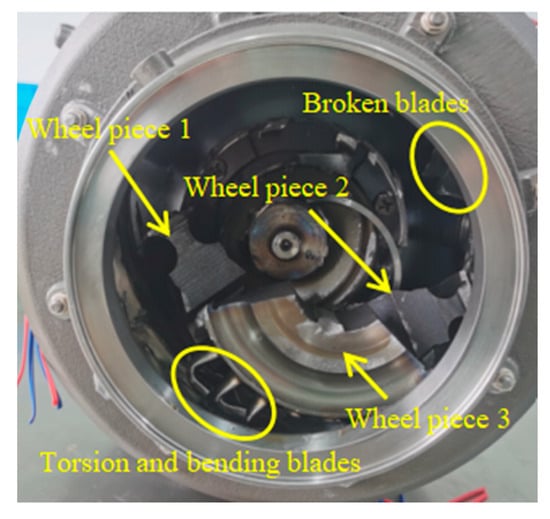
Figure 15.
Damage to the turbine wheel after removing the air intake pipe.
4. Discussion and Analysis
4.1. Component Damage
Figure 16, Figure 17, Figure 18, Figure 19 and Figure 20 compare the simulation and experimental results for the component damage, illustrating that the simulation and experimental results are consistent.
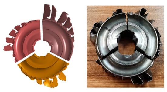
Figure 16.
Comparison of the simulation and experimental results for the damage situation of the turbine wheel.
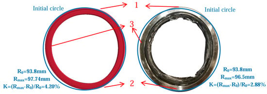
Figure 17.
Comparison of the simulation and experimental results for the damage situation of the containment ring.
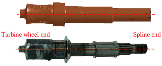
Figure 18.
Comparison of the simulation and experimental results for the damage situation of the turbine shaft.
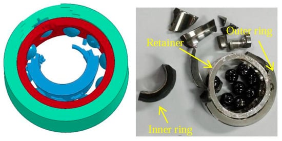
Figure 19.
Comparison of simulation and experimental results for the damage situation of bearing #1.
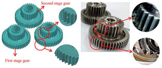
Figure 20.
Comparison of the simulation and experimental results for the damage situation of the planetary gears.
Figure 16 shows that both results exhibit burr fracture surfaces at the connection between the turbine wheel and shaft. A smooth fracture surface is observed between any two of the three wheel pieces. Moreover, the blades exhibit varying degrees of breakage, loss, torsion, and bending damage.
Figure 17 shows that the containment ring does not break, indicating its sufficient containment ability. The containment ring groove shows no obvious deformation, which verifies that the containment ring has a good ability to constrain the turbine wheel pieces in the axial direction. Bulges and plastic deformations are evident at positions 1 and 2 on the containment ring, which are formed by the impact of the first two wheel pieces on the containment ring. Position 3 exhibits a smaller plastic deformation than the other two positions because when the third wheel piece comes into contact with the containment ring, the containment ring has already undergone significant elastic–plastic deformation, thus allowing it to absorb some of the impact energy. In the simulation results, the outside radius of the containment ring is 93.8 mm, and the maximum outer circle radius of the containment ring after deformation is 97.74 mm. The maximum deformation rate is thus K = 4.2%. In the experimental results, the radius of the containment ring is 93.8 mm, and the maximum outer circle radius after impact is 96.5 mm. The radial deformation rate of the containment ring is K = 2.88%. These two results are in good agreement.
Figure 18 shows that under a large unbalanced load, the turbine shaft exhibits obvious bending deformation, the shaft head sways, and the joint surfaces between the wheel and shaft are coarsely fractured. From the overall deformation trend, the deformation at the end near the turbine wheel is the largest, and the closer it is to the spline, the smaller the deformation will be. In the experimental results, obvious compression marks appear on the position of bearing #1 near the turbine wheel because the unbalanced load during the wheel burst process causes significant radial deformation of the shaft, resulting in severe compression damage between the shaft and the inner ring of bearing #1. This indicates that bearing #1 bears the main load of the rotor shaft.
Figure 19 shows that under the squeeze of the bent turbine shaft, the inner ring of bearing #1 is compressed to deform and is damaged, the retainer undergoes significant wear and tear, and the outer ring of the bearing also suffers a certain degree of damage. If the wheel pieces detach from the turbine shaft and are ejected simultaneously, no unbalanced load is generated, and the damage to the turbine shaft and bearings is relatively small.
Figure 20 shows that the meshing surfaces of the first-stage planetary gears exhibit tooth surface wear and extrusion damage. The load causing the damage to the gears is mainly transferred through the engagement of the spline on the shaft. Minimal tooth surface damage is observed on the second-stage planetary gears. In particular, in the simulation results, nearly no damage to the second-stage planetary gears is evident. Overall, no severe damage is observed. The impact load transmitted from the shaft to the planetary gears contains a small amount of energy that is not absorbed by the first-stage gears. This is effectively absorbed by the meshing of the secondary-stage gears and the outside ring gear. The main reason for this is that the three planetary gears have the same structure and are evenly distributed around the driving gear, which can balance the inertial forces of the planetary gears with the driving and ring gears. In addition, the number of meshing teeth is sufficient to effectively dissipate the large impact load energy after the turbine wheel bursts. Ultimately, the load transferred to the output shaft is small.
In a word, the damage situation of the air turbine starter components obtained from simulation calculations and experiments is basically consistent. It can be inferred that the abrupt imposition of high-energy loads induces shaft misalignment, subsequently generating excessive compressive forces on both bearings and planetary gear trains. This failure mechanism primarily stems from alterations in the load transfer path within the air turbine starter system’s kinematic chain.
4.2. Load Transfer Path Analysis
The disparity in load transfer paths leads to variations in damage behavior. Figure 21 shows the two primary load transfer paths. In load transfer path 1, the centrifugal impact load from the wheel burst is first transferred to the extending inner wall of the exhaust casing. Subsequently, a part of the load is transferred to the outer wall of the exhaust casing. However, the majority of the load is transferred to the containment ring and then to the turbine nozzle and intake casing through the bolts and flange successively. In load transfer path 2, the unbalanced load resulting from the wheel burst in the shaft is transferred to the planetary gear set primarily through the two bearings, and part of the load is transmitted through spline meshing. The load is then transferred to the clutch assembly via a rotating transmission structure. Finally, it is transferred to the output shaft through the clutch assembly.
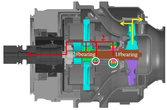
Figure 21.
Two main load transfer paths.
The calculation results for the first 0.15 ms are clear and sufficient to exhibit the stress distribution patterns of the main load transfer process.
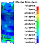
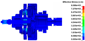
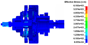
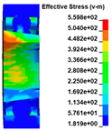
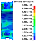
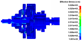
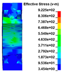
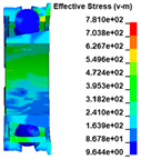
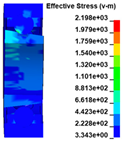
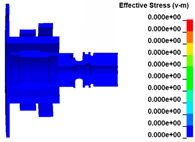
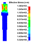
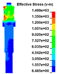
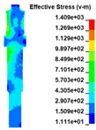
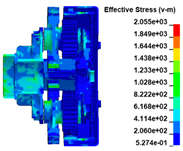
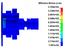
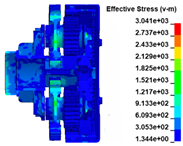
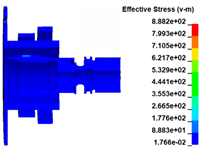
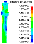
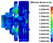
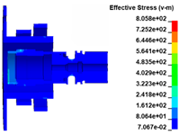
The stress distribution in the structures of load transfer path 1 is shown in Figure 22. Figure 17 shows that at t = 0.03 ms when the turbine wheel pieces are ejected, the material at the joint between the turbine wheel and shaft generates significant stress under a large centrifugal load, reaching the strength limit of the material. When the blades collide with the extending inner wall of the exhaust casing at t = 0.06 ms, the huge impact load causes a corresponding stress on the inner wall of the exhaust casing. As the degree of impact increases, the impact load increases gradually, and the stress level on the structure increases continuously. Subsequently, obvious stress distributions appear on the turbine nozzle and intake casing at t = 0.09 ms, indicating that the load on the inner wall of the exhaust casing is transferred to the nozzle and intake casing through the bolts and flange. The process between t = 0.12 and 0.15 ms is the main impact of the turbine wheel pieces on the containment ring. During this period, the stress level on the containment ring increases continuously, indicating that the impact load is further transferred to the containment ring. Subsequently, a portion of the load is successively transferred to the nozzle and intake casing through the aforementioned bolts and flange.
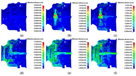
Figure 22.
Stress distribution in the structures of load transfer path 1 at t = (a) 0.00; (b) 0.03; (c) 0.06; (d) 0.09; (e) 0.12; and (f) 0.15 ms.
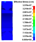
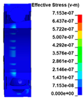
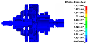
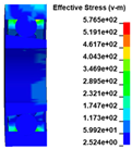
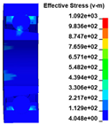
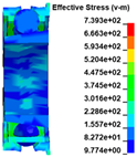
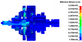
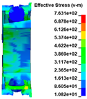
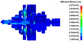
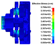
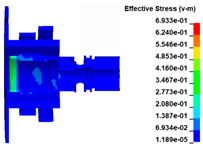
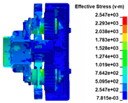
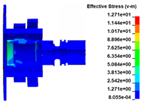
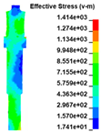
The stress distribution in the structures of load transfer path 2 is listed in Table 2. Table 2 indicates that when the turbine wheel pieces are ejected at t = 0.03 ms, a large stress is generated on the head of the shaft owing to the tearing effect of the wheel on the material under the action of centrifugal force. Simultaneously, an unbalanced load is generated on the shaft head, bending and deviating it from the equilibrium position. Owing to the initial compression load, stress is generated on the bearings, and the planetary gear set is initially subjected to a load from the bearings and spline. At t = 0.06 ms, as the shaft bending increases further, the stress distribution spreads toward the shaft end. The stress distribution on the planetary gear set also spreads backward. At t = 0.09 ms, the shaft is obviously bent and deformed, which compresses the inner ring of bearing #1 and generates significant stress on that bearing. From the stress distribution levels of the two bearings, bearing #1 can be observed to bear a greater load than bearing #2. The load on the planetary gear set is transferred further backward. At t = 0.12 ms, the load on the inner ring of the bearing is nearly transferred to the outer ring. The load on the entire planetary gear set is nearly transferred to the planetary gears. At t = 0.15 ms, under the compression load, the inner ring of bearing #1 starts to break. The load on the gears is further transferred to the rotating transmission structure and then to the output shaft through the clutch assembly. Throughout the process, the load on the output shaft is small because the gears dissipate most of the load energy.

Table 2.
Stress distribution in the structures of load transfer path 2.
4.3. Structural Dynamic Response
Figure 23 shows the acceleration versus time curves for different measurement points. To clearly display the vibration response of the entire experimental process, the vibration response of the casings is analyzed based on the acceleration–time curve for 0–8 ms. Table 2 lists the peak accelerations and times of occurrence for the measurement points. Figure 22 and Table 3 reveal that the intake casing (radial position corresponding to the containment ring) exhibits the highest vibration, with an average peak acceleration of 85,987 g. This is attributed to the vibration being transferred from two directions. The first vibration transmission direction arises from the wheel pieces directly impacting the extending inner wall of the exhaust casing, thus causing large vibrations in the exhaust casing. The vibration of the exhaust casing is transferred forward to the intake casing (radial position corresponding to the containment ring) through the bolts. This load transfer principle belongs to the load transfer path 1.
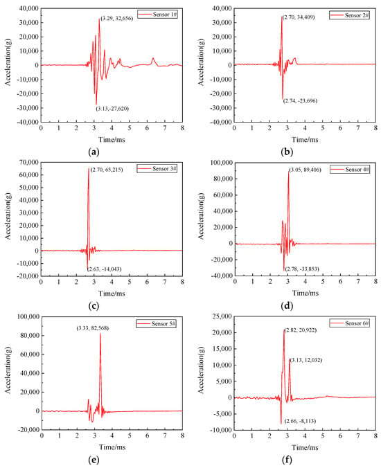
Figure 23.
Acceleration versus time curves for the casings: acceleration sensor (a) #1; (b) #2; (c) #3; (d) #4; (e) #5; and (f) #6.

Table 3.
Peak acceleration at each measuring point and corresponding peak time.
The simulation and experimental comparison of ATS vibration response are shown in Figure 24. Taking the simulation time of 2 ms as the time axis, the vibration signals extracted on the time axis of 2.5 ms to 4.5 ms were tested. The comparison results are shown in Figure 24. The results show that the vibration response trends of the key parts obtained through simulation and experiments are basically consistent, and the peak error of the vibration response is within 2.9% to 4.7%, as show in Figure 24.


Figure 24.
Simulation and experimental comparison of Vibration Response of ATS (a) Decelerator casing 1#; (b) Exhaust casing 2#; (c) Exhaust casing 3#; (d) Intake casing 4#; (e) Intake casing 5#; (f) Intake casing 6#.
The second direction of vibration transmission occurs when the wheel pieces impact the extending inner wall of the exhaust casing and the containment ring, thus generating significant vibration at the connection position. Subsequently, the vibration is transferred to the intake casing (radial position corresponding to the containment ring) through the bolts and flanges. The superposition of the vibrations in the two directions results in the maximum vibration of the intake casing (the radial position corresponding to the containment ring). The intake casing (position of inflow) has an average peak acceleration of 20,922 g, which is lower than that of the intake casing (radial position corresponding to the containment ring). This is because the vibration at the intake casing (position of the inflow) is mainly transferred from a single direction: the aforementioned vibration generated at the connection position between the extending inner wall of the exhaust casing and the intake casing is directly transferred forward, causing vibration at the position of the inflow on the intake casing. The exhaust casing exhibits the second-highest level of vibration, with an average peak acceleration of 49,812 g. This is due to the direct impact of the wheel pieces shattering the extending inner wall of the exhaust casing, thus generating significant vibration. The decelerator casing exhibits slightly lower vibration levels than the exhaust casing, with an acceleration peak of 32,656 g. This is because the vibration on the decelerator casing is transferred from the exhaust casing, and the vibration is attenuated by 34% during transmission. This load transfer principle belongs to the load transfer path 2.
Figure 23 and Table 3 also reveal that during the containment process of the starter, the wheel pieces first shatter the extending inner wall of the exhaust casing, and the vibration is initially transferred to the exhaust casing (average peak time of 2.70 ms) and subsequently to the decelerator casing (average peak time of 3.29 ms). Next, the wheel pieces impact the containment ring and shatter the guide vanes of the nozzle, resulting in the transfer of vibration from the connection location between the nozzle and the intake casing in both the forward and backward directions. The vibration is transferred forward to the position of the inflow on the intake casing at 2.82 ms and backward to the radial position corresponding to the containment ring of the intake casing at 3.19 ms (average peak time). These conclusions also partially verify the correctness of the load transfer path outlined in Section 4.1.
5. Conclusions
This study discusses the simulation of the ATS (Air Turbine Starter) whole-machine containment using simulation analysis methods, with more complex constraint settings applied in the full-structure simulation. A test for ATS containment was designed, and both the containment process and critical structural damage were obtained experimentally. The experimental results showed good agreement with the simulation results, thereby verifying the reliability of the simulation analysis method. Based on these experimental and simulation results, the load transfer paths and structural dynamic responses were analyzed to provide further guidance for ATS design. This approach is novel, differing from traditional component-level and specimen-level simulations. The key conclusions of this study are summarized as follows:
(1) This study successfully designed and implemented an ATS containment test and corresponding simulation analysis. A test bench was built for the test, where the turbine rotor was driven by airflow, and the turbine wheel was cut according to a predefined cutting plan to burst at the designed burst speed. Post-test observations showed that the containment ring underwent plastic deformation but remained unpierced. The turbine wheel pieces suffered impact damage: most blades were bent, twisted, or even detached, with only a few damaged blades remaining on the turbine wheel. The supporting bearings of the turbine shaft were damaged, and the planetary gears exhibited tooth surface wear and extrusion damage. These results confirm that the starter has excellent wheel-piece containment capability, and the experimental results are highly consistent with the simulation results.
(2) If all wheel pieces detach from the turbine shaft and are ejected simultaneously, no unbalanced load is generated, and the damage to the turbine shaft and bearings is relatively minor. In practice, however, the three pieces of the trisected burst turbine wheel are ejected sequentially: they first penetrate the extended inner wall of the exhaust casing, then impact the containment ring, causing significant elastic deformation of the containment ring. Concurrently, an unbalanced load is induced on the turbine shaft, leading to shaft oscillation and bending. The turbine shaft then squeezes the bearings, resulting in damage to the inner and outer rings of the bearings. This damage process gives rise to distinct patterns in load transfer paths.
(3) The starter exhibited two primary load transfer paths. Path 1 is responsible for containing high-energy pieces from the burst wheel, while Path 2 resists the large unbalanced load generated during the burst process and transmits it to the casings and output components. For Path 1: the centrifugal impact load from the wheel burst is first transferred to the extended inner wall of the exhaust casing; a portion of this load is then transferred to the outer wall of the exhaust casing, while the majority is transferred to the containment ring, and subsequently to the turbine nozzle and intake casing via bolts and flanges, successively. For Path 2: the unbalanced load induced by the wheel burst on the shaft is mainly transferred to the planetary gear set through two bearings, then transmitted to the clutch assembly via a rotating transmission structure, and finally transferred to the output shaft through the clutch assembly.
Load transfer paths are critical to the overall containment performance of an air turbine starter. Future research can focus on the following aspects:
(1) Quantitatively analyze the load transfer efficiency and stress distribution of the paths. Through simulation analysis, clarify the impact energy absorption efficiency of key components and the stress distribution law, providing a reference for the design of new ATS structures and the optimization of load transfer paths.
(2) Investigate the identification method for sudden high-energy load transmission paths. By adjusting the stiffness of key structures, observe the variation law and damage behavior of load transmission paths; use load sensitivity analysis to screen out the path that plays a decisive role in containment.
Author Contributions
Data curation, P.Z. and L.C.; Formal analysis, P.Z. and W.C.; Funding acquisition, L.C. and W.J.; Methodology, H.X.; Project administration, L.C. and W.J.; Resources, W.C. and Z.F.; Software, P.Z.; Supervision, H.X.; Writing—original draft, P.Z.; Writing—review and editing, P.Z. and W.J. All authors have read and agreed to the published version of the manuscript.
Funding
This work has been supported by National Natural Science Foundation of China (52405165), Postdoctoral Fellowship Program of CPSE (GZC20232263) and Aeronautical Science Foundation of China (20240028076002).
Data Availability Statement
The raw/processed data required to reproduce these findings cannot be shared at this time as the data also forms part of an ongoing study.
Acknowledgments
This project was supported by Aviation Key Laboratory of Science and Technology on Aero Electromechanical System Integration and AVIC Jincheng Nanjing Engineering Institute of Aircraft Systems.
Conflicts of Interest
The authors declare no conflicts of interest.
Nomenclature
| A | initial yield stress |
| B | strain hardening coefficient |
| C | strain rate constant |
| n | strain hardening exponent |
| m | temperature constant |
| D | damage parameter |
| σb | ultimate strength |
| σe | von Mises equivalent stress |
| equivalent plastic strain | |
| dimensionless strain rate | |
| T * | homologous temperature |
| increment in the equivalent plastic strain that occurs during integration | |
| fracture strain | |
| D1~D5 | failure constant |
| , | average tensile stress on the circumferential joint surface |
| A1, A2 | area of joint face |
| r | radius of the centrifugal slot |
| h | wheel thickness |
| angle of the circumferential load-bearing section | |
| M | mass of the trisection wheel |
| Rc | centroid radius |
| Rw | radius of the turbine wheel |
| wheel speed | |
| L | radial slot length |
References
- Pascoe, A. Start systems for aero gas turbines. Aircr. Eng. Aerosp. Technol. 2005, 77, 448–454. [Google Scholar] [CrossRef]
- US. Department of Transportation. The Potential for Fuel Tank Fire and Hydrodynamic Ram From Uncontained Aircraft Engine Debris; Report No. DOT/FAA/AR-96/95; Office of Aviation Research: Washington, DC, USA, 1997.
- Australian Transport Safety Bureau. Aviation Occurrence Statistics: 2001 to 2010; Report No. AR-2011-020; Australian Transport Safety Bureau: Canberra, Australia, 2011.
- Australian Transport Safety Bureau. Uncontained Engine Starter Failure-General Electric CF6-80E1-A3–Darwin Aerodrome; Report No. AO-2007-052; Australian Transport Safety Bureau: Canberra, Australia, 2007.
- Australian Transport Safety Bureau. In-Flight Engine Shut down Involving Airbus A330-302 B-18358; Report No. AO-2013-172; Australian Transport Safety Bureau: Canberra, Australia, 2013.
- AA Federal Aviation Regulations. Airworthiness Standards: Aircraft Engines; Federal Aviation Administration: Washington, DC, USA, 1984.
- CARR-25-R4; Airworthiness Standards for Transport Aircraft. Civil Aviation Administration of China: Beijing, China, 2011.
- Zhang, Y.; He, Z.; Xuan, H.; Liu, J.; Guo, X.; Mi, D.; Fang, Z. Study on the Optimal Design Method of the Containment Ring for an Air Turbine Starter. Aerospace 2023, 10, 624. [Google Scholar] [CrossRef]
- Xuan, H.J.; Wu, R.R. Aeroengine turbine blade containment tests using high-speed rotor spin testing facility. Aerosp. Sci. Technol. 2006, 10, 501–508. [Google Scholar] [CrossRef]
- Gálvez, F.; Cendón, D.; Enfedaque, A.; Sánchez-Gálvez, V. High strain rate and high temperature behaviour of metallic materials for jet engine turbine containment. J. Phys. IV 2006, 134, 269–274. [Google Scholar] [CrossRef]
- Teng, X.; Wierzbicki, T. Gouging and Fracture of Engine Containment Structure under Piece Impact. J. Aerosp. Eng. 2008, 21, 174–186. [Google Scholar] [CrossRef]
- Stahlecker, Z.; Mobasher, B.; Rajan, S.D.; Pereira, J.M. Development of reliable modeling methodologies for engine fan blade out containment analysis. Part II: Finite element analysis. Int. J. Impact Eng. 2009, 36, 447–459. [Google Scholar] [CrossRef]
- Sinha, S.K.; Dorbala, S. Dynamic loads in the fan containment structure of a turbofan engine. J. Aerosp. Eng. 2009, 22, 260–269. [Google Scholar] [CrossRef]
- Yang, B. Blade containment evaluation of civil aircraft engines. Chin. J. Aeronaut. 2013, 26, 9–16. [Google Scholar] [CrossRef]
- Bai, C.; Xuan, H.; Huang, X.; He, Z.; Hong, W. Containment ability and groove depth design of U type protection ring. Chin. J. Aeronaut. 2016, 29, 395–402. [Google Scholar] [CrossRef][Green Version]
- Kesare, P.; Chhapkhane, N.; Kumar, S.P. Determination of Impact Force for Turbine Housing Containment. Int. J. Eng. Tech. Res. 2016, 5, 612–615. [Google Scholar] [CrossRef]
- He, Q.; Xie, Z.; Xuan, H.; Liu, L.; Hong, W. Multi-blade effects on aero-engine blade containment. Aerosp. Sci. Technol. 2016, 49, 101–111. [Google Scholar] [CrossRef]
- Buchroithner, A.; Haidl, P.; Birgel, C.; Zarl, T.; Wegleiter, H. Design and testal Evaluation of a Low-Cost Test Rig for Flywheel Energy Storage Burst Containment Investigation. Appl. Sci. 2018, 8, 2622. [Google Scholar] [CrossRef]
- Sawaikar, P. A Review Paper on: Containment Test and Impeller Burst Simulation using Explicit Dynamics. Int. J. Res. Appl. Sci. Eng. Technol. 2019, 7, 144–151. [Google Scholar] [CrossRef]
- Wang, C.; Suo, T.; Li, Y.; Xue, P.; Tang, Z. High-velocity impact responses of 2618 aluminum plates for engine containment systems under combined actions of projectile form and oblique angle. Chin. J. Aeronaut. 2019, 32, 1428–1441. [Google Scholar] [CrossRef]
- Eryilmaz, I.; Guenchi, B.; Pachidis, V. Multi-blade shedding in turbines with different casing and blade tip architectures. Aerosp. Sci. Technol. 2019, 87, 300–310. [Google Scholar] [CrossRef]
- Zekan, H.E.; Guo, X.; Xuan, H.; Shan, X.; Fan, X.; Chen, C.; Hong, W. Characteristics and mechanisms of turboshaft engine axial compressor casing containment. Chin. J. Aeronaut. 2021, 34, 10. [Google Scholar] [CrossRef]
- Sepúlveda, H.; Valle, R.; Pincheira, G.; Prasad, C.S.; Salas, A.; Medina, C.; Tuninetti, V. Dynamic numerical prediction of plasticity and damage in a turbofan blade containment test. Proc. Inst. Mech. Eng. Part L J. Mater. Des. Appl. 2023, 237, 2551–2560. [Google Scholar] [CrossRef]
- Guo, R.; Ji, Y. Remaining useful life prediction for bearing of an air turbine starter using a novel end-to-end network. Meas. Sci. Technol. 2023, 34, 2578–2588. [Google Scholar] [CrossRef]
- Giard, J.R. Air turbine starter turbine wheel containment. SAE Trans. 1984, 93, 459–463. Available online: https://www.jstor.org/stable/44467159 (accessed on 6 August 2025).
- Biswas, S.; Ganeshachar, M.D.; Sridhar, B.R.; Ramachandra, S. Failure analysis of an air turbine starter. J. Fail. Anal. Prev. 2010, 10, 259–263. [Google Scholar] [CrossRef]
- Chen, L.; Xuan, H.; Jia, W.; Liu, J.; Fang, Z.; Zheng, Y. Neck Structure Optimal Design of the Turbine Wheel for Containment Design of the Air Turbine Starter. Aerospace 2023, 10, 802. [Google Scholar] [CrossRef]
- Cakmak, O.; Sanliturk, K.Y. A dynamic model of an overhung rotor with ball bearings. Proc. Inst. Mech. Eng. Part K J. Multi-Body Dyn. 2011, 225, 310–321. [Google Scholar] [CrossRef]
- He, Q.; Xie, Z.; Xuan, H.; Hong, W. Ballistic testing and theoretical analysis for perforation mechanism of the fan casing and fragmentation of the released blade. Int. J. Impact Eng. 2016, 91, 80–93. [Google Scholar] [CrossRef]
- Bai, C.; Xuan, H.; Mi, D.; Zhu, Z. Modeling method of connecting bolts in centrifugal compressor containment structure. J. Aerosp. Power 2019, 34, 313–320. [Google Scholar] [CrossRef]
- Johnson, G.R.; Cook, W.H. A constitutive model and data for metals subjected to large strains, high strain rates and high temperatures. In Proceedings of the Seventh International Symposium on Ballistics, Hague, The Netherlands, 19–21 April 1983. [Google Scholar]
- Johnson, G.R.; Cook, W.H. Fracture characteristics of three metals subjected to various strains, strain rates, temperatures and pressures. Eng. Fract. Mech. 1985, 21, 31–48. [Google Scholar] [CrossRef]
- Fan, X. Numerical Simulation and Structural Optimization of U-section Containment Rings. Master’s Thesis, Zhejiang University, Hangzhou, China, 2021. [Google Scholar]
- Yu, M.; Wang, J.; Xuan, H.; Xiong, W.; He, Z.; Qu, M. Simulation and Experimental Study of Gas Turbine Blade Tenon-Root Detachment on Spin Test. Aerospace 2024, 11, 629. [Google Scholar] [CrossRef]
- Zhang, Y.; He, Z.; Liu, C.; Wang, M.; Xuan, H.; Qu, M.; Fang, Z. Research on the explosion release method and damage mechanism of titanium alloy fan blade. J. Mech. Sci. Technol. 2023, 37, 13. [Google Scholar] [CrossRef]
Disclaimer/Publisher’s Note: The statements, opinions and data contained in all publications are solely those of the individual author(s) and contributor(s) and not of MDPI and/or the editor(s). MDPI and/or the editor(s) disclaim responsibility for any injury to people or property resulting from any ideas, methods, instructions or products referred to in the content. |
© 2025 by the authors. Licensee MDPI, Basel, Switzerland. This article is an open access article distributed under the terms and conditions of the Creative Commons Attribution (CC BY) license (https://creativecommons.org/licenses/by/4.0/).
