Abstract
As a core component of an aero-engine, the aerodynamic performance of the nacelle is essential for the overall performance of an aircraft. However, the direct design of a three-dimensional (3D) nacelle is limited by the complex design space consisting of different cross-section profiles and irregular circumferential curves. The deep manifold learning-assisted geometric multiple dimensionality reduction method combines autoencoders (AE) with strong capabilities for non-linear data dimensionality reduction and class function/shape function transformation (CST). A novel geometric dimensionality reduction method is developed to address the typical constraints of nacelle parameterization. Low-dimensional latent variables are extracted from the high-dimensional design space to achieve a parametric representation of 3D nacelle manifolds. Compared with traditional parametric methods, the proposed geometric dimensionality reduction method improves the accuracy and efficiency of geometric reconstruction and aerodynamic evaluation. A multi-objective optimization framework is proposed based on deep manifold learning to increase the efficiency of 3D nacelle design. The Pareto front curves under drag divergence constraints reveal the correlation between the geometry distribution and the surface isentropic Mach number distribution of 3D nacelles. This paper demonstrates the feasibility of the proposed geometric dimensionality reduction method for direct multi-objective optimization of 3D nacelles.
1. Introduction
The aerodynamic design of civil aircraft is becoming increasingly critical with respect to fuel consumption, pollution emissions, and other performance indicators. As an essential component of an aero-engine, the aerodynamic performance of its nacelle has a direct and sensitive impact on the aircraft [1,2] Therefore, research on efficient aerodynamic design of nacelles has received much attention, and numerous outstanding aerodynamic specialists have made significant contributions to nacelle design in recent years [3,4,5,6,7,8,9].
An essential issue of nacelle design is the geometric dimensionality reduction method. Choosing a geometric dimensionality reduction method with enough flexibility, simplicity, and smoothness to describe the complex 3D geometry of a cylindrical-like nacelle is crucial for developing a nacelle aerodynamic design method. The most common and traditional nacelle design method simplifies the optimization of 3D nacelle geometry into individual optimizations of one or more two-dimensional (2D) cross-sections, which are described by a proper parametric method (e.g., Hicks-Henne [10], CST [11] and B-Spline [12]). As shown in Figure 1, these 2D cross-sections are usually chosen as typical circumferential profiles, e.g., at the angle of 0, 90, and 180 [13]. For example, Wang et al. [14] describe the 2D cross-sections using the parametric section (PARSEC) method. They replace the original geometry profiles of the corresponding cross-sections by laminar flow designs to rapidly improve the local laminar length on the external surface of the nacelle. The results show that the local transition position of the nacelle is obviously delayed. However, for non-axisymmetric nacelles, this simplified method only designs the selected cross-sections, whereas other cross-sections are obtained by interpolation. The measure of some 2D cross-sections is zero in 3D space, and it is difficult to adequately impose geometric constraints for each profile due to the inseparable connection between cross-sections during optimization [15]. The geometric constraints may differ significantly between different cross-sections, and the relationship between geometry and aerodynamic performance is nonlinear. Therefore, this method cannot provide an accurate, efficient and global description of a complete 3D nacelle geometry.
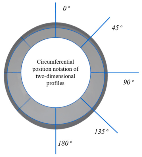
Figure 1.
Typical cross-section of nacelle external profile for tradition nacelle design.
In order to evaluate the global aerodynamic performance more accurately, the geometric dimensionality reduction method in a 3D view was gradually valued and developed. In general, 3D nacelle nacelle optimization is very expensive. Therefore, researchers have explored 3D geometric dimensionality reduction methods for nacelles to improve the implementability of 3D nacelle optimization. Wang et al. [15] propose a nacelle inlet design approach that introduces more 3D geometric considerations. This method selects the dimensions for subsequent optimization according to a top-down order of importance with mathematical orthogonality instead of random picking aided by experience. Although this method reduces the dependence on the designer’s experience in the 3D design space, it is still essentially a 2D cross-section design method, and the issue of interpolation in other domains beyond the designed cross-section remains. Li et al. [16] develop the free-form deformation (FFD) method for arbitrary space geometry based on a non-uniform rational B-spline (NURBS) basis function. They employ this method for the global parameterization of the nacelle-pylon geometry, conducting an optimization of the DLR-F6 wing-body-pylon-nacelle, significantly reducing the shock wave strength around the pylon surface. He et al. [17] propose CYFFD (cylindrical free-form deformation) for designing axisymmetric and non-axisymmetric nacelles by adding coordinate transformation and a virtual frame strategy, which can capture the unique circumferential and radial deformation characteristics and ensure the continuity of derivatives and curvature on the frame boundary. They conduct a parametric fitting test of the nacelle by applying CYFFD. The results show that the fitting method is effective and has a strong parametric capability for non-axisymmetric nacelles. The above studies made significant contributions to the development of geometric dimensionality reduction methods for 3D nacelles. However, there is still potential for further improvement in describing the 3D nacelle geometry globally, flexibly and efficiently.
In the selection of geometric dimensionality reduction methods, accuracy of the global representation and computational effort are an unavoidable contradiction. In the case of 3D design, more design parameters are often chosen to describe the physical properties of the 3D nacelle more accurately, but this may lead to the curse of dimensionality and reduce design efficiency. If the number of design parameters is reduced to improve the feasibility of an optimal design, this may reduce the potential nacelle design space. In order to solve the above problem with artificial intelligence technology, intelligent tools provide a new option for geometric dimensionality reduction. Intelligent tools efficiently extract low-dimensional latent variables from a high-dimensional aerodynamic shape design space [3] to ensure global geometric control and reconstruction accuracy.
Manifold learning recovers the low-dimensional manifold structure from high-dimensional sampled data; that is, it finds a low-dimensional parameterization in the high-dimensional space and solves the corresponding mapping for achieving dimensionality reduction or data visualization. Principal Component Analysis (PCA) is a typical manifold learning algorithm, and Wang et al. [18] have used this method in dimensionality reduction of the airfoil. In addition, deep learning techniques, such as variational encoders (VAE) [19] and generative adversarial networks (GANs) [20], have been tried for their ability to learn low-dimensional representations from complex and highly distributed data. In previous nacelle designs, deep learning techniques have been employed in the construction of surrogate models for optimization processes [6,7,8,9] and can provide the inspiration for geometric dimensionality reduction of a 3D nacelle. Compared to traditional dimension reduction methods, deep learning methods can employ a compact set of variables and the prior experience to model the highly complex variability of the design [21]. Chen et al. [21] developed a new parametric method based on Bézier-GAN, which employs latent code and noise variables to encode major and minor geometry variations. This method intelligently reduces the design space by filtering out unrealistic airfoil shapes. The design results show that the application of the Bézier-GAN parametric method accelerates the convergence and achieves better design results. Du et al. [22] propose an intelligent parametric method by coupling B-Spline and a generative adversarial network (GAN). The BSpline-GAN model is trained to generate the airfoil geometry, thus automatically reducing the original design space while maintaining a sufficient range of design freedom. The above studies improve the effectiveness of parametric methods in the airfoil, which make a great contribution to the development of geometric dimensionality reduction methods combined with deep learning technology.
Compared to the wing, the nacelle has a higher geometric complexity and a more apparent 3D aerodynamic effect. In the design process of a 3D nacelle, the geometry of the individual cross-sections needs to be designed, and the structure of the circumferential curve needs to be considered. The circumferential curve may behave irregularly due to constraints such as ground clearance. Therefore, it is necessary to develop a 3D parametric method that can accurately and efficiently describe a general complex 3D nacelle geometry. In the field of aerodynamic design, the currently developed parametric method using manifold learning combined with GAN [21,22] is basically a generative method, which cannot extract information from geometry to latent feature variables. Especially in the multi-objective optimization of a 3D nacelle, an efficient and accurate 3D geometric dimensionality reduction method is of great significance in the optimization process.
In addition, a specialized and complete optimization framework often plays a crucial role in addressing the specific problem [23,24]. Compared with improving only one part of the optimization process, constructing a specific optimization framework enhances the coherence and pertinence of the application. In this study, several complex elements, e.g., 3D configuration and multi-objective design, constitute a complex optimization problem. In order to improve the efficiency and feasibility of direct 3D nacelle design, an aerodynamic optimization framework based on deep manifold learning-assisted geometric multiple dimensionality reduction is proposed. The main contributions of this paper are as follows:
- (a)
- To address the difficulty of keeping balance between efficiency and accuracy of 3D nacelle parametric methods, the proposed method combines the traditional CST method with an auto-encoder to achieve a high-fidelity and efficient multiple dimensionality reduction of 3D nacelle geometry;
- (b)
- To address the lack of an efficient multi-objective optimization design method in direct 3D nacelle design, a novel aerodynamic design framework is developed based on a genetic algorithm and the proposed geometric dimensionality reduction method;
- (c)
- Taking the laminar flow area and drag coefficient as design objectives, Pareto front curves are given under different drag divergence constraints. The geometric distribution and the surface isentropic Mach number distribution of 3D nacelles with different aerodynamic performance are analyzed to provide experience for the subsequent aerodynamic design of a 3D nacelle.
The content of this paper is organized as follows. Section 2 describes the CFD validation and mesh analysis. Section 3 introduces the proposed geometric multiple dimensionality reduction method for a 3D nacelle. Section 4 introduces the novel 3D nacelle aerodynamic optimization framework and analyzes the optimization results. Section 5 gives some conclusions and prospects.
2. CFD Validation and Mesh Analysis
In this paper, the design object is a high bypass ratio nacelle model, whose drag accounts for about 5% of the total aircraft drag with great aerodynamic design significance [25]. The flow field of the nacelle is simulated via ANSYS Fluent. In our previous work, CFD validation was conducted [3]. Here, the simulation conditions are set as follows. The incoming Mach number is 0.85, the inlet flow is 407 kg/s, the Reynolds number is 4.4592 × 10⁷, the fan area is 5.14 m2, the attack angle is 5°, and the temperature is 216.7 K. The Reynolds-Averaged Navier–Stokes (RANS) model is selected for the steady numerical simulation. The turbulence intensity is 0.1%, the turbulent viscosity ratio is 10%, and the viscosity coefficient is 1.7894 × 10⁻⁵. No-slip boundary condition is used for the mesh surface, pressure outlet condition is chosen for the aip surface, and Pressure Far-Field is used for the far-field boundary. Target Mass Flow is 407 (kg/s). The incoming flow is an ideal gas that obeys the Sutherland formula. Since the transition position from laminar flow to turbulence is concerned, the transition SST four-equation model is selected as turbulence model. The drag of nacelle is expressed as follows [26]:
where is the lateral force on the inlet flow pipe, is the lateral force on the wake and is the aerodynamic drag on the nacelle housing. The inlet flow pipe is the flow pipe enclosing the inlet streamline of the engine, the outlet flow pipe is the flow pipe enclosing the outlet streamline of the engine, and nacelle housing is the shell mounted on the engine core component. The drag coefficient of nacelle is expressed as follows:
where is the density of the far field, is the velocity of the far field and is surface area of the wing of 197 m2 as the reference area.
The mesh independence verification is shown in Figure 2. The number of grid nodes increases gradually from Figure 2a–d. The total number of the fine mesh is 10,105,400. The comparison of the drag coefficient of a three-dimensional nacelle using different mesh is shown in Table 1. As a result, mesh b (total number is 5,506,500) was selected. Compared with the fine mesh, the difference in drag coefficient of the nacelle is 2.20%, which is in good agreement with the results of fine mesh. The selected mesh in the axial view and far field is shown in Figure 3.
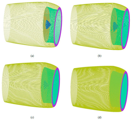
Figure 2.
Mesh for 3D nacelle with decreasing element size: (a) mesh a; (b) mesh b; (c) mesh c; (d) mesh d.

Table 1.
Drag coefficient of three-dimensional nacelle.
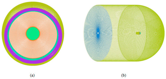
Figure 3.
Mesh topology of mesh b: (a) axial view; (b) far field.
3. Geometric Multiple Dimensionality Reduction Based on Deep Manifold Learning
In recent years, deep learning has become a widely used and effective method for extracting features [27,28,29,30]. In this paper, a novel geometric multiple dimensionality reduction method based on deep manifold learning for 3D nacelles is proposed. This method combines autoencoders and CST to construct a low-dimensional non-linear parametric representation of the complex 3D nacelle geometry and to reconstruct the 3D geometry from latent variables. This section introduces the above geometric multiple dimensionality reduction method for a 3D nacelle.
3.1. The Concept of Deep Manifold Learning
In the early stage of development of dimensionality reduction algorithms, the main idea of projection-based dimensionality reduction methods is to project the original data into the low-dimensional feature space to achieve dimensionality reduction [31]. Two classical methods based on projection are Principal Component Analysis(PCA) [32] and Linear Discriminant Analysis (LDA) [33], but both algorithms have difficulty in revealing the inherent nonlinear structure of the data for complex space [34]. With the development of deep learning technology, a dimensionality reduction algorithm based on deep manifold learning has been realized and developed.
The dimensionality reduction of manifold learning is shown in Figure 4. is the manifold satisfying geometric constraint , is the manifold satisfying geometric constraint . and are open sets. For the two open set, two mappings exist, , . The parameter fields and are presented as the feature space. The transformations between the local coordinates exist, and the descriptions of the nacelle parameters in different manifold systems can be transformed into each other. The transformation from the manifold to the coordinates is the core of the dimensionality reduction method. The inverse transformation , i.e., the transformation from local coordinates to the manifold is the core of the reconstruction of manifold.
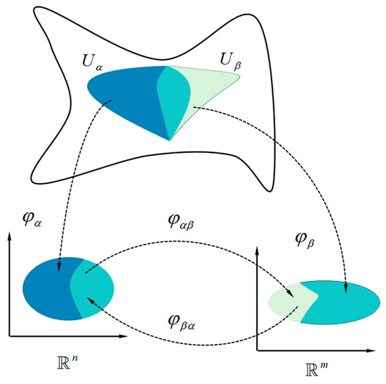
Figure 4.
The concept of manifold learning.
3.2. Autoencoders (AE)
In this paper, AE are chosen as the core section of the parametric method for achieving dimensionality reduction and reconstruction of 3D nacelle manifold due to the strong deep learning capabilities. Autoencoders (AE) [35] are the unsupervised architecture of Deep Neural Networks (DNNs), which are designed to learn an alternative representation of input data through the process of data compression and reconstruction. Data processing involves two main steps: compression and reconstruction through one or more hidden layers, i.e., encoding and decoding, respectively. AE have been used as a special deep learning technique in many situations, including dimensionality reduction, feature extraction, and data denoising. Due to the excellent capability in nonlinearity, versatility, and robustness for dimensionality reduction, AE have been widely used in image processing, face recognition, drug discovery, and biomedical imaging.
AE are employed as the essential tool in the proposed 3D nacelle parameterization to define a reversible, non-linear, low-dimensional parameterization process for high-dimensional input information [36]. The basic structure of AE is divided into four layers shown in Figure 5: input layer, output layer, hidden layers, and embedding layer, arranged in hourglass-like shape [37]. The central layer, called the embedding layer, defines the low-dimensional latent parameter domain. The output layer has the same dimension as the input layer associated with the 3D geometry of the nacelle. The part of the network that connects the input to the latent parameter domain is called the encoder, and the part connecting the output to the latent parameter domain is called the decoder. Through appropriate training, AE can extract the low-dimensional latent features of the flow field by deep learning from the high-dimensional design space. Corresponding to the process of deep manifold learning in Figure 5, the parametric mapping of nacelle manifolds (Encoder) is , and the reconstruction mapping of manifolds (Decoder), i.e., the inverse mapping, is .
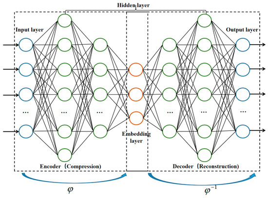
Figure 5.
The structure of AE for deep manifold learning.
In the 3D parametric framework, and , corresponding to encoder and decoder, respectively, are expressed as follows:
where denotes the errors of the input and output which are denoted by Mean Squared Error (MSE) in this paper.
3.3. Geometric Multiple Dimensionality Reduction of Three-Dimensional Nacelle
In this paper, a 3D nacelle geometric multiple dimensionality reduction method with combined CST and AE is proposed, which improves the existing framework of 3D nacelle parameterization and design. Different from the traditional parametric method based on typical cross-sections, this method can better demonstrate the 3D aerodynamic effects of the nacelle, making the direct design of 3D nacelle more efficient.
The geometric multiple dimensionality reduction is introduced in Figure 6. The data points describing the 3D geometry of the nacelle are represented by two dimensions: axial and circumferential coordinate. In the geometric multiple dimensionality reduction, axial dimensionality reduction is conducted by CST and the parameter matrix is generated after axial dimensionality reduction. Then, the circumferential dimensionality reduction is conducted by deep manifold learning and achieved by the encoder of AE. Then the parameters of 3D nacelles are obtained. The network structure of the encoder and decoder is symmetric. Through the decoder and the nacelle reconstruction, the 3D nacelle manifold is obtained. The traditional design of a nacelle is based on typical two-dimensional cross-sections, thus only the axial dimensionality reduction of two-dimensional cross-sections is needed. CST is an effective method for dimensionality reduction of the axial two-dimensional cross-section of nacelle [13,38,39]. The process of secondary dimensionality reduction employing AE is a new paradigm of dimensionality reduction for the complex geometry by deep manifold learning. Manifold learning assumes that the data in high-dimensional space distributes in a manifold of lower dimensions. Based on this assumption, data analysis and dimensionality reduction are carried out. The nacelle geometry with the design constraint has apparent 3D features, and the profiles of different longitudinal cross-sections also have the specific geometric law, which makes it possible to represent the geometry of the high-dimensional nacelle with low-dimensional parameters based on manifold learning.
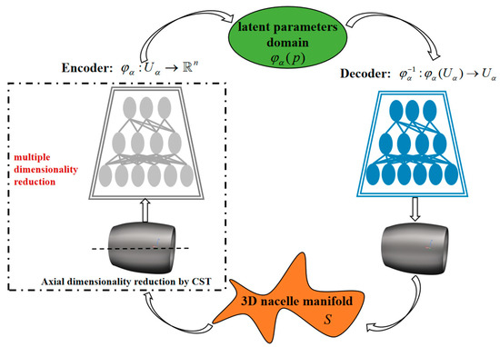
Figure 6.
The framework of geometric multiple dimensionality reduction method.
The specific method of geometric multiple dimensionality reduction is described as follows. In the axial dimensionality reduction, CST method includes category function and shape function . The geometry of axial cross-section can be expressed by combining the two functions as:
where and are the coordinates of the axial profile on the X-axis and Z-axis, is the chord length of the axial profile, is the coordinates of the trailing edge of the axial profile with respect to the Z-axis. The category function is defined as:
where and directly determine the category of geometric shapes. According to the geometric characteristics of the nacelle axial profile, the values are and .
The shape function is defined using the form of weighted sum based on n-order Bernstein polynomial:
where is the coefficient of Bernstein polynomial, and is the weight factor of corresponding items.
The 77 × 163 data points are extracted to complete the nacelle outer profile description. Since the nacelle studied in this paper has a symmetric mirror configuration, the amount of data points can be reduced to 38 × 163. After axial CST dimensionality reduction, the axial direction is represented by 6 CST parameters, that is, after axial CST dimension reduction, the data points are reduced from 38 × 163 to 38 × 6. If the data is concatenated by rows or columns to form a vector, the dimension of this vector is 228. Then a secondary dimensionality reduction by AE is conducted. The encoder and decoder of AE is trained on 50,000 nacelle samples which have been accumulated in the previous work of the research group. Here, 45,000 samples are in the training set, and 5000 samples are in the test set. The training sets are as follows: batch_size = 64, learning rate = 2 × 10⁻³, weight_decay = 1× 10⁻⁵. The training setting of AE is shown in Table 2. The number of layers of the neural network are determined through numerical experiments. The AE’s structure of the two parametric methods are the same. The structure of the Encoder and Decoder is symmetric. The activation function is Rectified Linear Unit (ReLU) [33], and the number of nodes in the three-layer neural network is 1024, 512, and 64, respectively. In conclusion, the process of 3D nacelle multiple dimensionality reduction is shown in Table 3.

Table 2.
The training setting of AE.

Table 3.
The process of 3D nacelle multiple dimensionality reduction.
Figure 7 shows the convergence curves of AE. The X axis represents the epoch for training and the Y axis represents the loss function. Here, the loss function is the value of MSE (Mean Square Error). The black curve is the convergence process of dimensionality reduction only using AE. The red curve is the convergence process of the multiple dimensionality reduction (MDR). The axial dimensionality reduction by CST is firstly conducted before AE in MDR to improve efficiency. The results indicate that MDR has a faster convergence rate and smaller error than only using AE.
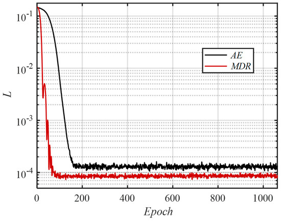
Figure 7.
Convergence curves of AE.
Figure 8 shows the counters of geometric reconstruction error of the 3D nacelle by AE and MDR. Figure 8a,c,e show the geometric reconstruction error of the 3D nacelle by using only AE trained for 10 epochs, 50 epochs, and 500 epochs. The surface of the 3D nacelle is clearly not smooth, and a large geometric error exists after training for 10 epochs. Figure 8c shows the geometric reconstruction error of the 3D nacelle by applying AE trained for 50 epochs. The surface of the 3D nacelle still has a relatively large error. Figure 8e shows the geometric reconstruction error by applying AE trained for 500 epochs. Corresponding to Figure 7, the convergence has reached 500 epochs, and the geometric error in the 3D nacelle reconstruction is small. Figure 8b,d,f show the geometric reconstruction error of the 3D nacelle by using MDR trained for 10 epochs, 50 epochs, and 500 epochs. Compared with Figure 8a,c,e, when trained for the same epochs, the smoothness of the 3D nacelle surface is better, and the geometric errors are smaller when applying MDR for geometric dimensionality reduction. Results also illustrate the high geometric accuracy and excellent surface quality of employing the well-trained MDR.
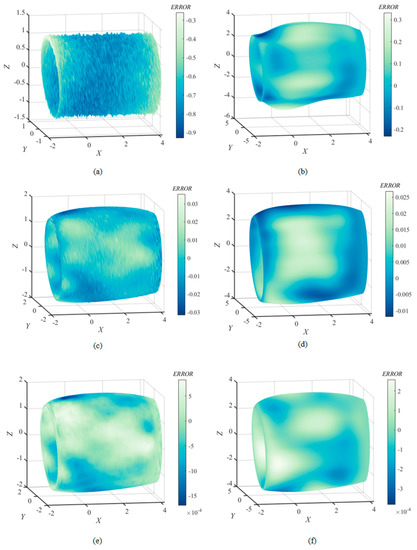
Figure 8.
Geometric reconstruction error of 3D nacelle: (a) 10 epochs using only AE; (b) 10 epochs using MDR; (c) 50 epochs using only AE; (d) 50 epochs using MDR; (e) 500 epochs using only AE; (f) 500 epochs using MDR.
3.4. Geometric Multiple Dimensionality Reduction Method Verification
The traditional nacelle parametric method based on typical cross-sections is employed to describe the nacelle shown in Figure 9. The traditional nacelle parametric method simplifies the 3D nacelle geometry into several individual 2D cross-sections and describes each 2D cross-section by CST. Here, five typical cross-sections are selected, each with six CST parameters, for a total of 30 parameters.
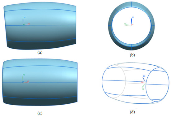
Figure 9.
Traditional nacelle parameterization based on typical cross-sections: (a) side view; (b) front view; (c) vertical view; (d) three-dimensional skeleton diagram.
In this section, the geometric reconstruction and aerodynamic accuracy of the novel proposed 3D nacelle parametric method are compared with the traditional typical cross-section parametric method. Figure 10 indicates the geometry reconstruction error distribution of three parametric methods. Among them, 16 parameters are selected in the parametric method only using AE, and 16 parameters are selected in the MDR. In terms of geometric reconstruction of the 3D nacelle, the geometry reconstruction error of the parametric method based on MDR is much smaller than that of the parametric method based on AE and the traditional typical cross-section parametric method. Moreover, the geometric surface of the nacelle only using AE is rough and unsuitable for performing aerodynamic simulations. Figure 11 indicates the isentropic Mach number (Ma) error distribution of the parametric method based on MDR and traditional typical cross-section parametric method. The results show that the aerodynamic accuracy of the parametric method based on MDR is much higher than that of the traditional parametric method.
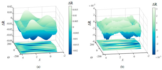
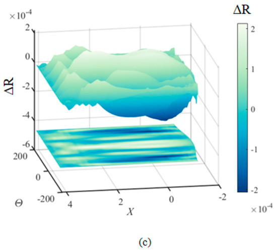
Figure 10.
Distribution of geometry reconstruction error: (a) traditional typical cross-section parametric method; (b) parametric method based on AE; (c) parametric method based on MDR.
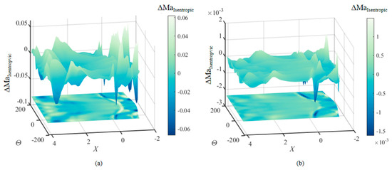
Figure 11.
Distribution of isentropic Ma error: (a) traditional typical cross-section parametric method; (b) parametric method based on MDR.
The quantitative description of the geometry and aerodynamic error are presented in Table 4 and Table 5. The relative error is calculated as the basis of the original nacelle described by measuring the point matrix for the original geometric surface. Table 5 shows the average geometry and isentropic Ma error of the traditional typical cross-section parametric method and the parametric method based on MDR, demonstrating the superiority of the novel proposed parametric method in terms of geometry and aerodynamic accuracy. Table 5 shows the drag coefficient and error of traditional typical cross-section parametric method and the parametric method based on MDR. Compared with the drag coefficient of the original nacelle, the relative error employing the traditional typical cross-section parametric method reaches 3.414%, while the relative error employing the parametric method based on MDR is only 0.142%. The above results illustrate that the parametric method of deep manifold learning describes the 3D nacelle geometry more accurately and appropriately for conducting the subsequent aerodynamic design.

Table 4.
Average error of traditional and proposed parametric methods.

Table 5.
Drag coefficient and relative error of parametric methods.
4. Aerodynamic Optimization of Three-Dimensional Nacelle
4.1. D Nacelle Aerodynamic Optimization Framework Based on Deep Manifold Learning
The traditional genetic algorithm involves three genetic operators, i.e., mutation, crossover, and selection. In this paper, the novel aerodynamic optimization framework is developed based on the geometric multiple dimensionality reduction method and genetic algorithm for the direct 3D nacelle design as shown in Figure 12 and introduced as follows:
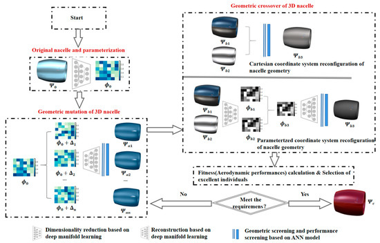
Figure 12.
Aerodynamic optimization framework of 3D nacelle design.
Step 1: Parameterization of original nacelle by multiple dimensionality reduction. The original nacelle configuration is defined as . Using the multiple dimensionality reduction method, the parameter representation of 3D nacelle is defined as .
Step 2: Geometric mutation of 3D nacelle. Parameters of the original nacelle are disturbed and used to generate new nacelles through the decoder. The mutation is to add an amount to each parameter. Geometric screening and aerodynamic screening are carried out for mutational geometry. Aerodynamic screening is realized by dynamically trained ANN model for aerodynamic evaluation. Then the nacelles meeting the screening conditions are evaluated by CFD.
Step 3: Geometric crossover of 3D nacelle. Optimal individuals are randomly selected from the existing population. These individuals are reconfigured in two dimensions: Cartesian coordinate system reconfiguration of nacelle geometry and parameterized coordinate system reconfiguration of nacelle geometry, respectively. Geometric screening and aerodynamic screening are carried out for the reconstructed configurations. Aerodynamic screening is realized by dynamically trained ANN model for aerodynamic evaluation. Then the nacelles meeting the screening conditions are evaluated by CFD.
Step 4: Selection of excellent individuals. The fitness calculation of 3D nacelle is conducted by CFD, and excellent individuals are selected.
Step 5: Determine whether the convergence is satisfied. If so, the optimization process ends; If not, the cycle of mutation is repeated.
The pseudocode of the proposed optimization algorithm (Algorithm 1) is as follows:
| Algorithm 1 3D Nacelle Aerodynamic Optimization Framework |
| 1: I = 0; //Evolutionary population generation; 2: Initialize ; //Initializing the population; 3: = MDRd (); //Multiple dimensionality reduction; 4: while (not Terminate-Condition) do //If the termination condition is not met, the loop { 5: I ++; //loop; 6: //Mutation; 7: = Mutation (); //Disturb to obtain new nacelle parameters; 8: screening(MDRc ()); //Acquisition of new nacelle configurations by mutation, and geometric and performance screening, MDRc: Multiple dimensionality reconfiguration; 9: Fitness (); //Select excellent individuals from the existing population; 10: // Crossover; 11: = MDRd ();// MDRd: Multiple dimensionality reduction; 12: screening ([Crossover (), MDRc (Crossover ())])// Acquisition of new nacelle configurations by crossover, and geometric and performance screening, MDRc: Multiple dimensionality reconfiguration; 13: Fitness (); Select excellent individuals from the existing population; } 14: end while 15: return |
4.2. Dynamic Training and Assisted Optimization of ANN Model for Aerodynamic Performance Evaluation
The aerodynamic optimization of 3D nacelle in the direct design requires a large number of numerical calculations of the flow field, which is computationally costly. Therefore, in order to adequately improve the data utilization, it is necessary to use a data-driven approach to construct an aerodynamic surrogate model for aiding the 3D direct design.
According to the characteristics of the direct design (shown in Figure 12), the 3D nacelle aerodynamic direct design based on deep manifold learning requires continuous iterations of the geometric configuration, and an aerodynamic performance evaluation model is required to evaluate the new nacelles, thus the 3D nacelles with excellent aerodynamic performance are screened. Since the amount of data in the database varies in each stage of the optimization process, especially in the initial stage of the optimization, the database size is small and insufficient to support accurate aerodynamic performance evaluation. The dynamically trained ANN model for aerodynamic evaluation is constructed and assisted the optimization of 3D nacelle. The ANN model is retrained for each 100 expansion of the data amount to update the network and improve the prediction accuracy. The ANN model screens out the nacelles with excellent aerodynamic performance in the optimization process, which reduces meaningless calculations and improves design efficiency. The specific process is shown in Figure 13, and the ANN performance screening conditions are introduced in Equation (12).
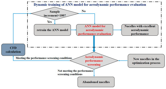
Figure 13.
Dynamic training and assisted optimization of ANN model.
4.3. Optimization Problem Description
In this section, the direct 3D nacelle design based on deep manifold learning is conducted. The design requirement is to reduce the drag coefficient and increase the laminar flow ratio . The design condition is and the attack angle is 5°. The optimization problem can be stated as follows:
where is the drag coefficient of the configuration , is the laminar flow ratio of the configuration , is the geometric space of the nacelle that satisfies the constraint, is the drag divergence Mach number, and is the constraint of drag divergence Mach number. Here, the value of is 0.89. The drag divergence Mach number is the critical Mach number when the slope of drag divergence curve is equal to 0.01, i.e., . Here, the critical slope is valued as 0.01. In the engineering design, several discrete Mach number conditions are often performed to estimate the drag divergence Mach number. In order to provide continuous gradient information for optimization, a continuous drag divergence criterion is defined as :
In order to meet the drag divergence constraint and improve the efficiency of optimization, a penalty function based on the drag divergence criterion is introduced:
where is a penalty factor and here. The above optimization problem Equation (8) is modified as follows:
In Section 4.2, the conditions for applying ANN model to aerodynamic performance screening are as follows:
For the multi-objective aerodynamic optimization problem in this paper, the Pareto front curve is expected to be solved. Figure 11 shows an illustration of the Pareto front curve. Assuming that is a feasible solution to the multi-objective optimization problem (Equation (10)), there is no in the feasible domain that satisfies . Then is considered to be a Pareto optimal solution. In Figure 14, A and B are Pareto-optimal solutions which are not dominated by any solution. All Pareto optimal solutions constitute the set of Pareto optimal solutions, and these solutions are mapped by the objective function to construct the Pareto front shown in Figure 14. In this paper, two Pareto front curves are expected to be derived for the two conditions, i.e., the drag divergence Mach number greater than 0.88 and the drag divergence Mach number greater than 0.89.
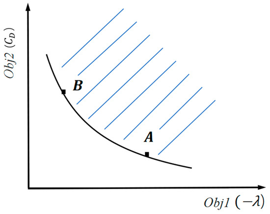
Figure 14.
The illustration of the Pareto front curve.
4.4. Optimal Results and Discussion
Figure 15 shows the distribution of all 3D nacelles in the design process. According to Equation (10), the criterion space is spanned by the drag coefficient , the laminar flow ratio , and the drag divergence criterion . The laminar flow ratio is the ratio of surface laminar flow area to total area. There are 3100 nacelle configurations in the figure, and their spatial 3D positions represent their aerodynamic performance. The color in the surface represents the distribution of the surface isentropic Mach number. In this diagram, the overall distribution of 3D nacelles in aerodynamic space is beneficial for studying the relationship between the surface isentropic Mach number distribution and aerodynamic performance. The Pareto front of the 3D nacelle can be obtained through the above optimization process corresponding to the design specifications. Furthermore, relatively continuous nacelle CFD calculations with a specific gradient are obtained for the above aerodynamic indicators, which contributes to further exploring the correlation between the aerodynamic performance, isentropic Mach number, and 3D nacelle geometry.
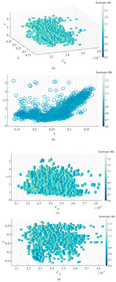
Figure 15.
3D nacelles distribution in design process: (a) three-dimensional view; (b) front view; (c) side view; (d) vertical view.
Figure 16 shows Pareto front curves of the 3D nacelle design. The Pareto front is the set of optimization solutions for another aerodynamic performance to the current optimum condition maintaining a constant drag coefficient or laminar flow ratio with the constrained drag divergence Mach number. The Pareto front could illustrate the design potential of the 3D nacelle in multi-objective optimization. The Pareto front 1 represents the set of optimization solutions when the drag divergence Mach number is greater than 0.88. The Pareto front 2 represents the set of optimization solutions when the drag divergence Mach number is greater than 0.89. It can be seen that the drag divergence constraint has a significant influence on the design potential of the laminar flow ratio and drag coefficient, specifically, the relaxation of the drag divergence constraint has a positive effect on the reduction of the drag coefficient and the improvement of the laminar flow ratio. The left domain of the Pareto front is the drag-dominated design of the nacelle, and the upper domain of the Pareto front is the laminar-dominated design. For the drag-dominated nacelle, the isentropic Mach number of the surface shows that when the drag is low to a specific value, the axial single shock wave distribution of the surface is destroyed and develops into the double shock wave. The double shock wave distribution is beneficial to reduce the drag of the 3D nacelle and improve the drag divergence performance. However, as the first shock wave of the double shock wave configuration is closer to the inlet, the strong inverse pressure gradient directly interrupts the laminar flow, which is unfavorable to maintaining the laminar flow. This phenomenon is more evident when the drag divergence Mach number constraint is greater than 0.89. The design limit for a drag-dominated nacelle is the drag of 2.2 × 10⁻³, corresponding to the laminar flow ratio of 20%. Nacelles with too large laminar flow ratio correspond to a higher drag loss and are not recommended in engineering. The Pareto front provides a reference for the subsequent determination of drag divergence performance, laminar flow performance, and drag performance.
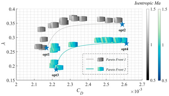
Figure 16.
The Pareto front curves of 3D nacelle multi-objective design.
As shown in Figure 16, opt1 and opt2 are the drag-dominated and laminar-dominated solutions in Pareto front curve 1, respectively. Opt3 and opt4 are the drag-dominated and laminar-dominated solutions in Pareto front curve 2, respectively. In each optimization result in Figure 17, (Ⅰ) represents the geometry of the 3D nacelle. The maximum radius of opt1 and opt2 are smaller than that of opt3 and opt4. The maximum radius of the laminar-dominated nacelle is greater than that of the drag-dominated nacelle with the uniform drag divergence constraint, which allows the flow to accelerate more slowly at the front of the nacelle, effectively delaying the emergence of the adverse pressure region and benefiting the delay of the laminar transition. In addition, the extension of the surface favorable pressure region length also leads to a stronger shock wave intensity. Therefore, the maximum laminar flow length and minimum drag could not be achieved simultaneously.
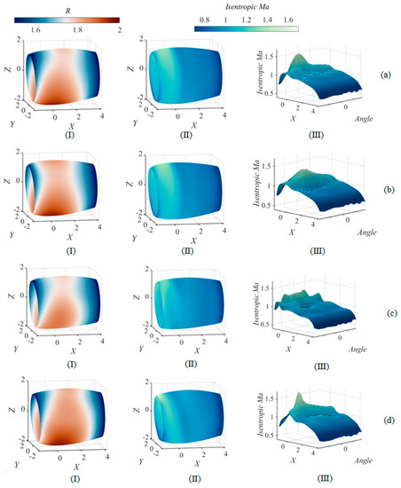
Figure 17.
Geometry and flow field analysis of 3D nacelle optimization results: (a) opt1; (b) opt2; (c) opt3; (d) opt4.
In each optimization result in Figure 17, (II) represents the isentropic Mach number distribution in the physical view of the 3D nacelle surface, and (III) represents the isentropic Mach number distribution of the 3D nacelle surface after decomposition in the column coordinate. Table 6 shows characteristic values of the optimal 3D nacelle flow fields. The results show that the shock wave intensity of the laminar-dominated nacelle is greater than that of the drag-dominated nacelle. When the drag divergence Mach number is greater than 0.88 (Pareto front 1), the suction spike strength at the leading edge of the laminar-dominated nacelle is lower than that of the drag-dominated nacelle. The suction spike strength is the surface pressure profile at the minimum value of the pressure at the leading edge, which has a significant effect on laminar flow. When the drag divergence Mach number is greater than 0.89 (Pareto front 2), although the suction spike strength at the leading edge of the laminar-dominated nacelle is relatively high, it only occurs in the narrow region near the 0° cross-section. However, in the flow field of the drag-dominated nacelle, the suction spike strength at the leading edge appears over a wide region, which is unfavorable for the maintenance of laminar flow.

Table 6.
Characteristic values of optimal 3D nacelle flow fields.
5. Conclusions
To address the issue of 3D nacelle aerodynamic multi-objective optimization in engineering, a novel aerodynamic optimization framework based on deep manifold learning-assisted geometric multiple dimensionality reduction is proposed in this paper. The CST method and AE are combined to construct the low-dimensional non-linear parametric representation of the complex 3D nacelle geometry and to reconstruct the 3D geometry from latent variables.
Different from the commonly used geometric dimensionality reduction method based on typical 2D cross-sections of the 3D nacelle, a parameter matrix is first generated by CST along the axial direction, and the secondary dimensionality reduction by AE is conducted based on deep manifold learning. The geometric multiple dimensionality reduction method improves the accuracy and efficiency of 3D geometric reconstruction and aerodynamic performance evaluation and provides the means to analyze the aerodynamic design law of 3D nacelle under fixed constraints.
Based on the proposed multiple dimensionality reduction method of a 3D nacelle, a novel 3D nacelle direct multi-objective optimization framework is developed. The method considers 3D aerodynamic effects in the 3D nacelle direct design process and optimizes the 3D nacelle geometry by mutation, crossover, and selection. In order to improve data utilization during the direct design process, the ANN model for aerodynamic performance evaluation is dynamically trained and assists the optimization of the 3D nacelle. The optimization results illustrate Pareto Front curves of the 3D nacelle under drag divergence constraints. The geometric distribution and the surface isentropic Mach number distribution of 3D nacelles with different aerodynamic performance are analyzed. Moreover, the Pareto front illustrates the design potential of the 3D nacelle in drag divergence performance, laminar flow performance, and drag performance. The results demonstrate the feasibility of the proposed method in the direct multi-objective optimization of 3D nacelles.
In future work, the geometric dimensionality reduction method and aerodynamic design method for coupling engine pylon and nacelle will be further investigated in the engineering design.
Author Contributions
Conceptualization, G.S.; methodology, C.W. and L.W.; Formal analysis, C.W., L.W. and C.C.; software, C.W. and Y.H.; Investigation, C.W. and L.W.; writing—original draft preparation, C.W. and L.W.; writing—review and editing, C.C., G.S., Y.H. and S.Z. All authors have read and agreed to the published version of the manuscript.
Funding
This research received no external funding.
Conflicts of Interest
The authors declare that they have no conflict of interest in this work.
References
- Robinson, M.; MacManus, D.G.; Christie, R.; Sheaf, C.; Grech, N. Nacelle design for ultra-high bypass ratio engines with CFD based optimisation. Aerosp. Sci. Technol. 2020, 113, 106191. [Google Scholar] [CrossRef]
- Kim, H.; Lee, M. Flow simulation of a supersonic airplane with installed engine nacelle. Aerosp. Sci. Technol. 2021, 117, 106900. [Google Scholar] [CrossRef]
- Wang, C.; Wang, S.; Wang, L.; Cao, C.; Sun, G.; Li, C.; Yang, Y. Framework of nacelle inverse design method based on improved generative adversarial networks. Aerosp. Sci. Technol. 2022, 121, 107365. [Google Scholar] [CrossRef]
- Tejero, F.; Christie, R.; MacManus, D.; Sheaf, C. Non-axisymmetric aero-engine nacelle design by surrogate-based methods. Aerosp. Sci. Technol. 2021, 117, 106890. [Google Scholar] [CrossRef]
- Tang, Z.; Zhang, M.; Hu, X. Optimal shape design and transition uncertainty analysis of transonic axisymmetric natural laminar flow nacelle at high Reynolds number. Aerosp. Sci. Technol. 2022, 121, 107345. [Google Scholar] [CrossRef]
- Yao, Y.; Ma, D.; Yang, M.; Zhang, L.; Guo, Y. Adaptive-surrogate-based robust optimization of transonic natural laminar flow nacelle. Chin. J. Aeronaut. 2021, 34, 36–52. [Google Scholar] [CrossRef]
- Fang, X.; Zhang, Y.; Li, S.; Chen, H. Transonic Nacelle Aerodynamic Optimization Based on Hybrid Genetic Algorithm. In Proceedings of the 17th AIAA/ISSMO Multidisciplinary Analysis and Optimization Conference, Washington, DC, USA, 13–17 June 2016. [Google Scholar]
- Li, S.; Zhong, Y. A Turbofan-Engine Nacelle Shape Design and Optimization Method for Natural Laminar Flow Control. In Proceedings of the ASME Turbo Expo: Turbine Technical Conference and Exposition, Seoul, Republic of Korea, 13–17 June 2016. [Google Scholar]
- Zhong, Y.; Li, S. A 3D Shape Design and Optimization Method for Natural Laminar Flow Nacelle. In Proceedings of the ASME Turbo Expo: Turbine Technical Conference and Exposition, Charlotte, NC, USA, 26–30 June 2017. [Google Scholar]
- Hicks, R.; Henne, P. Wing design by numerical optimization. J. Aircraft 1977, 5, 407–412. [Google Scholar]
- He, W.; Liu, X. Improved aerofoil parameterisation based on class/shape function transformation. Aeronaut. J. 2019, 123, 310–339. [Google Scholar] [CrossRef]
- Vuruskan, A.; Hosder, S. Impact of Turbulence Models and Shape Parameterization on Robust Aerodynamic Shape Optimi-zation. J. Aircraft. 2019, 56, 1099–1115. [Google Scholar] [CrossRef]
- Wang, S.; Sun, G.; Li, C. Natural Laminar Flow Optimization of Transonic Nacelle Based on Differential Evolution Algorithm. J. Aerosp. Eng. 2019, 32, 06019001. [Google Scholar] [CrossRef]
- Wang, S.; Sun, G.; Chen, W.; Zhong, Y. Database self-expansion based on artificial neural network: An approach in aircraft design. Aerosp. Sci. Technol. 2017, 72, 77–83. [Google Scholar] [CrossRef]
- Wang, S.; Cao, C.; Wang, C.; Wang, L.; Sun, G. A Nacelle Inlet Design Approach with More Three-Dimensional Geometric Con-sideration. Aerosp. Sci. Technol. 2021, 112, 106621. [Google Scholar] [CrossRef]
- Li, J.; Gao, Z.; Huang, J.; Zhao, K. Aerodynamic design optimization of nacelle/pylon position on an aircraft. Chin. J. Aeronaut. 2013, 26, 850–857. [Google Scholar] [CrossRef]
- He, X.; Bai, J.; Li, L.; Yang, T.; Zhang, Y. CYFFD Parameterization Method for Cylindrical Components of Aircrafts. J. Northwest. Polytech. Univ. 2018, 36, 1027–1036. [Google Scholar] [CrossRef]
- Wang, X.; Wang, S.; Tao, J.; Sun, G.; Mao, J. A PCA–ANN-based inverse design model of stall lift robustness for high-lift device. Aerosp. Sci. Technol. 2018, 81, 272–283. [Google Scholar] [CrossRef]
- Kingma, D.; Welling, M. Auto-Encoding Variational Bayes. arXiv 2014, arXiv:1312.6114v11. [Google Scholar]
- Goodfellow, I.; Pouget-Abadie, J.; Mirza, M.; Xu, B.; Warde-Farley, D.; Ozair, S.; Courville, A.; Bengio, Y. Generative Adversarial Nets. In Proceedings of the 28th Conference on Neural Information Processing Systems (NIPS), Montreal, QC, Canada, 7–12 December 2014; pp. 2672–2680. [Google Scholar]
- Chen, W.; Chiu, K.; Fuge, M.D. Airfoil Design Parameterization and Optimization Using Bézier Generative Adversarial Networks. AIAA J. 2020, 58, 4723–4735. [Google Scholar] [CrossRef]
- Du, X.; He, P.; Martins, J.R. Rapid airfoil design optimization via neural networks-based parameterization and surrogate modeling. Aerosp. Sci. Technol. 2021, 113, 106701. [Google Scholar] [CrossRef]
- Agarwal, D.; Marques, S.; Robinson, T. Aerodynamic Shape Optimisation Using Parametric CAD and Discrete Ad-joint. Aerospace 2022, 9, 743. [Google Scholar] [CrossRef]
- Yao, W.; Marques, S.; Robinson, T.; Armstrong, C.; Sun, L. A reduced-order model for gradient-based aerodynamic shape op-timisation. Aerosp. Sci. Technol. 2020, 106, 106120. [Google Scholar] [CrossRef]
- Faust, G.K.; Mungur, P. Nacelle Design; General Electric Company: Cleveland, OH, USA, 1987; pp. 17–20. [Google Scholar]
- Yufei, Z.; Haixin, C.; Song, F.; Miao, Z.; Meihong, Z. Drag prediction method of powered-on civil aircraft based on thrust drag bookkeeping. Chin. J. Aeronaut. 2015, 11, 1023–1033. [Google Scholar]
- Wu, H.; Liu, X.; An, W.; Lyu, H. A generative deep learning framework for airfoil flow field prediction with sparse data. Chin. J. Aeronaut. 2022, 35, 470–484. [Google Scholar] [CrossRef]
- Sun, X.; Cao, W.; Liu, Y.; Zhu, L.; Zhang, W. High Reynolds number airfoil turbulence modeling method based on machine learning technique. Comput. Fluids 2022, 236, 105298. [Google Scholar] [CrossRef]
- Zhu, L.; Zhang, W.; Sun, X.; Liu, Y.; Yuan, X. Turbulence closure for high Reynolds number airfoil flows by deep neural networks. Aerosp. Sci. Technol. 2021, 110, 106452. [Google Scholar] [CrossRef]
- Wu, H.; Liu, X.; An, W.; Chen, S.; Lyu, H. A deep learning approach for efficiently and accurately evaluating the flow field of supercritical airfoils. Comput. Fluids 2020, 198, 104393. [Google Scholar] [CrossRef]
- Harsanyi, J.C.; Chang, C.I. Hyperspectral image classification and dimensionality reduction: An orthogonal subspace projection approach. IEEE Trans. Geosci. Remote Sens. 1994, 32, 779–785. [Google Scholar] [CrossRef]
- Cheng, X.; Chen, Y.R.; Tao, Y.; Wang, C.Y.; Kim, M.S.; Lefcourt, A.M. A novel integrated PCA and FLD method on hyperspectral image feature extraction for cucumber chilling damage inspection. Trans. ASAE 2004, 47, 1313. [Google Scholar] [CrossRef]
- Bandos, T.V.; Bruzzone, L.; Camps-Valls, G. Classification of hyperspectral images with regularized linear discriminant analysis. IEEE Trans. Geosci. Remote Sens. 2009, 47, 862–873. [Google Scholar] [CrossRef]
- Ma, L.; Crawford, M.M.; Tian, J. Local manifold learning-based k-nearest-neighbor for hyperspectral image classification. IEEE Trans. Geosci. Remote Sens. 2010, 48, 4099–4109. [Google Scholar] [CrossRef]
- Bourlard, H.; Kamp, Y. Auto-association by multilayer perceptrons and singular value decomposition. Biol. Cybern. 1988, 59, 291–294. [Google Scholar] [CrossRef]
- Omata, N.; Shirayama, S. A novel method of low-dimensional representation for temporal behavior of flow fields using deep autoencoder. AIP Adv. 2019, 9, 015006. [Google Scholar] [CrossRef]
- He, X.; He, Q.; Chen, J.-S. Deep autoencoders for physics-constrained data-driven nonlinear materials modeling. Comput. Methods Appl. Mech. Eng. 2021, 385, 114034. [Google Scholar] [CrossRef]
- Christie, R.; Heidebrecht, A.; Macmanus, D. An Automated Approach to Nacelle Parameterization Using Intuitive Class Shape Transformation Curves. J. Eng. Gas Turbines Power 2017, 139, 062601. [Google Scholar] [CrossRef]
- Cao, F.; Hu, X.; Zhang, M.; Tang, Z. Transonic natural laminar flow nacelle optimization design at high Reynolds number. J. Aerosp. Power 2021, 36, 1729–1739. [Google Scholar]
Disclaimer/Publisher’s Note: The statements, opinions and data contained in all publications are solely those of the individual author(s) and contributor(s) and not of MDPI and/or the editor(s). MDPI and/or the editor(s) disclaim responsibility for any injury to people or property resulting from any ideas, methods, instructions or products referred to in the content. |
© 2023 by the authors. Licensee MDPI, Basel, Switzerland. This article is an open access article distributed under the terms and conditions of the Creative Commons Attribution (CC BY) license (https://creativecommons.org/licenses/by/4.0/).