Abstract
This study introduces the BIM (building information modeling)-GIS (geographic information system) conceptual mapping (B2GM) standard ISO N19166 and proposes a mapping mechanism. In addition, the major issues concerning BIM-GIS integration, and the considerations that it requires, are discussed. The B2GM is currently being standardized by the spatial-information international standardization organization TC211. Previous studies on BIM-GIS integration seem to focus on the integration of different types of model schemas and on the implementation of service interfaces. B2GM concerns the clear definition of the conditions and methods for mapping the object information required from the user’s use-case viewpoint for city-scale mapping. The benefits of the B2GM approach are that the user is able directly control the BIM-GIS linkage and integration process in order to acquire the necessary objection information. This can reveal cases of possibly unclear BIM-GIS integration outside the black box in an explicit and standard way, so that the user can distinctively predict the final output obtainable from the BIM-GIS integration. This study examined B2GM in terms of its development background, components, and several utilization examples, as well as the levels and considerations of the integration of different BIM-GIS models.
1. Introduction
The integration of data through geographic information system (GIS)-based building information modeling (BIM) has emerged as an important area of research for the mining of valuable information that can support decision-making.
In particular, in order to realize smart city services such as facilities including effective building and energy management, we need to consider the information perspective, which can be represented by considering use cases related to services and combining the BIM and GIS information that we want to use, including information on the building and infrastructure objects in a city. We also need to consider other heterogeneous data models, such as facility management (FM) database systems. These databases can be legacy systems.
There have been some attempts to harvest the rich information in BIM and use it in GIS, but there is no established way to map the information elements between the two worlds. A proper mapping method is clearly required. From the viewpoint of GIS, there are many benefits related to using BIM information in GIS applications. Some examples are:
- Indoor service implementation, such as emergency management (for example, directing and finding evacuation paths in a fire situation);
- Outdoor–indoor linking services, such as seamless navigation; and
- Effective facility/energy/environment management considering objects related to BIM based on GIS.
However, an unclear BIM-GIS model integration method may cause the following problems.
- Difficulty for the user to predict the model integration results.
- In the model integration process, the information necessary for the execution of the use-case may be deleted.
- Information unnecessary for the execution of use-case may be retained. The unnecessary information may make the management of the integrated model difficult and may increase the time and cost of management.
- Erroneous integrated noise information may lead to bad results in the execution of services or in decision-making.
The problems mentioned may cause the user to hesitate to use the BIM-GIS model integration information. To solve this problem, the user should be able to define the BIM-GIS integration process in a standardized way [1] from the point of view of use, and the results should be clearly predictable.
Previous studies related to BIM-GIS integration often suggest the development of integrated models needed for specific usecases. This approach fixes the integration method or part of the integration process for the realization of a specific use case, such as an information query method using an ontology model [2,3,4,5,6], a web-service-based model for integration system development [7,8], data transformation methods using commercial tools [9,10,11,12], and a model schema development method [13,14,15,16,17]. These references will be examined in more detail through a literature review.
This study proposes the BIM-GIM integration method based on B2GM (19166), which is a standard under ISO/TC211. B2GM enables flexible information mapping and integration considering the relevant problems. B2GM focuses on the clear definition of conditions and processes to map the object information necessary from the user’s use-case viewpoint onto the city scale. The proposed method includes the BIM-GIS element, geometry, and a property set mapping method including the external dataset. Considering the standardization of the BIM-GIS mapping requirements, the BIM and GIS models to be mapped were generalized and expressed if possible. In the case studies and the survey, the BIM-GIS integrated information type, utilization and level were analyzed.
2. Materials and Methods
To develop the conceptual mapping, related current research trends were studied and their characteristics were analyzed to compare and investigate the respective technologies in relation to the present study like Figure 1.
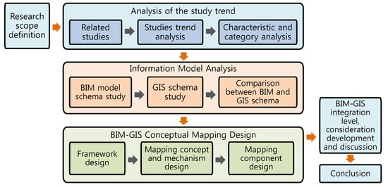
Figure 1.
Research flow.
The research progress situation and limits were reviewed through the examination of the existing literature. The scope of the literature survey was limited to the following keywords and purposes.
- The literature surveyed includes BIM, GIS and similar keywords.
- The purpose of research includes integration and linkage, standardization, and service development.
Based on the literature review and the analysis of information models such as BIM and GIS, B2GM was designed to solve the integration problems. After comparing solutions that are similar to the B2GM concept, the benefits will be discussed. Finally, the BIM-GIS integration level, considerations and conclusions of the study are derived.
3. Results
3.1. Overview of Recent Research Trends
For the GIS and BIM categories, standard models are proposed to support interoperability. Their respective model schema structures are different, making their integration difficult. Diverse approaches are used for the research on GIS-BIM integration, but this chapter summarizes the research contents from the perspectives of ontological modeling, integrated web services, schema mapping, and schema expansion and development.
1. Ontological modeling
Interoperability implementation based on ontological models enables data integration at the conceptual level. A method was proposed by which, after the extraction of IFC and GIS information, an RDF (resource description framework) model was created to ask questions [2]. In addition, a study was conducted to propose a method by which, after defining an RDF dictionary about the IFC wall structure, information is requested through SPARQL, and the results are expressed [3]. To apply this method, the components of the heterogeneous model composition should be converted to a triple structure.
A study was conducted to propose a semi-automatic ontological method for geospatial integration [4]. It proposed heterogeneous data inter-model mapping operators and modeling tools for data integration.
For the integration of GIS and CAD data, a study was conducted by applying the ontological modeling method [5]. It suggested that the use of the automated query interpreter (AQI) method makes a semantic interoperation between data models and processes possible. This method is operated by asking ontological questions about individual heterogeneous data and finally integrating the inquiry results. Yet another study was conducted on BIM-GIS integration based on RDF [6]. It converts IFC and GML (geography markup language) into RDF and expresses it in a graph model.
2. Integrated web service
Data extraction in BIM, GIS and other heterogeneous models can be provided as a web service in order to obtain the data required for the development of applications. The web services phase 4 (OWS-4) of the GIS standardization non-government council Open Geospatial Consortium (OGC) is currently developing IFC for GIS (IFG) in order to express BIM data in CityGML. IFC conversion to geography markup language (GML) and GML conversion to IFC are possible through a concept similar to extensible stylesheet language (XSLT) [7]. In addition, a study was conducted on the method of using web services to demonstrate building models in GIS [8].
3. Data mapping
BIM can be converted to another model, but with limitations. This conversion is a mapping-based process and usually consists of several mapping conditions and rules.
There was a study where the IFC-based partial model was used in a co-work (teamwork) environment in connection with the mapping method [9]. It indicated that it is complicated and inconvenient to use approaches such as STEP (STandard for the Exchange of Product model data) tools and express data management (EDM), which are known as schema-based modeling tools. Instead, it proposed the mapping of source model elements into target model elements using the EXPRESS-X mapping schema. For mapping, STEP-P21 [10] implements interoperability using the IFC inter-printer. STEP-P21, known as the STEP physical file format, provides a clear text encoding method for information exchange, and the ISO 10303-21 clear text encoding of the exchange structure is the standard. This method, however, can be used only with in-depth knowledge of the STEP-P21 specifications, and it does not handle the methods of importing heterogeneous datasets into IFC and binding and mapping them.
Yet another method of schema mapping is the information extraction technology using the generalised model subset definition schema (GMSD)-based partial model and the partial model query language (PMQL) [11]. GMSD was designed based on the object-oriented language concept, and is classified into the object filing division and the attribute view definition division. This method is similar to the SQL SELECT text and IFC IfcPropertySet.
A study was conducted on mapping using ETL (extract, transform, and load) [12]. Using the ESRI commercial ETL software, it extracted the BIM data required for the implementation of a use case of landscaping planning.
4. Schema extension and development
Attempts were made to resolve problems arising from the BIM-GIS schema difference by developing a new common schema. The IFC-CityGML schema structure difference was analyzed using the unified building model (UBM) for the purpose of proposing a new schema in a bid to resolve such problems [13]. There was a study on extending the BIM model using the application domain extension (ADE) method [14].
To implement GIS-based use cases such as site selection and fire management in the construction category, a study was conducted to propose a method of incorporating BIM information into GIS [15]. To convert data from IFC to the ESRI schema structure, the said study developed the persistent schema level model view schema. A method was proposed to convert this information into transient temporary object model data, incorporate it into the GIS geographical data model, and store it in ESRI’s shapefile and geodatabase structure [16]. The results of the study were verified by interviewing experts regarding the ISO 9126-1 quality factors. A study was conducted to demonstrate a flood model using ADE [17]. Most studies on ADE should focus on the implementation of the data required for special use cases, thus limiting their scope.
3.2. Research Review Analysis
The research reviewed above can be divided into the following categories.
As shown in Table 1, most of studies on BIM-GIS model integration focus on the ontological model, schema expansion, the development of web services and applications, and the development of commercial-solution-based data extraction modules. This study focuses on the distinctive definition method for the conditions and processes to map the external data necessary from the user’s use-case viewpoint, as well as the BIM object information in the GIS model.

Table 1.
Analysis of research.
3.3. Analysis of Standard Models
3.3.1. Overview
The BIM and GIS schemas have different development purposes, concepts and structures, thus making it difficult to integrate data if specific criteria are not given. This chapter analyzes the schema structure to be considered from the BIM-GIS integration viewpoint. The existing BIM and GIS commercial data format has a binary structure and is not open. Thus, based on IFC and CityGML, which are the representative standard models of BIM and GIS, the schema structure and features are analyzed herein.
3.3.2. IFC Standard Model
IFC is a data exchange format that was developed to describe building information. This format is neural and open. The IFC format was developed for the purpose of data exchange in 1995 by IAI (International Alliance Interoperability), a council formed in 1995 mainly by AEC (architecture, engineering and construction) companies in the U.S. and Europe. It has been developed and maintained in buildingSMART.
IFC has now evolved into the IFC4 version, and it is described in the EXPRESS language, which is based on the entity relationship model, a model that can describe object-oriented structures.
In IFC4, classes are defined by being extended into the kernel package (which defines the key object classes), into the three basic extended packages (i.e., control, product and process) extended from the kernel, and into the five AEC/FM common packages (i.e., building services, components, absence of buildings, management factors, and facility objects) extended from the extended packages.
IFC4 consists of eight packages in the AEC/FM domain in individual common packages, and of 21 resource packages resulting from the basic object types (e.g., the quantity and material used to define the attributes of the construction elements) defined and classified by kind.
IFC describes the information schema in the EXPRESS language based on the object-oriented concept. Focusing on the interoperation of architectural information to enable the reuse of the information, it provides a total of over 700 objects, including various architectural elements, materials, and processes, which are extended from the kernel objects.
IFC is used together with IFD (International Framework for Dictionaries, ISO 12006-3) and with IDM (Information Delivery Manual, ISO 29481-1:2010), an IFC information exchange method. Here, IDM aims to define the construction project process and to provide guidelines for the inter-process information exchange required when using BIM. IDM is defined in terms of BPMN (business process model and notation) and ER (exchange requirement), which are part of BPM (business process management) technologies, to tailor the universal IFC to the mutual process relevancy, type of consumption information, information exchange method, etc.
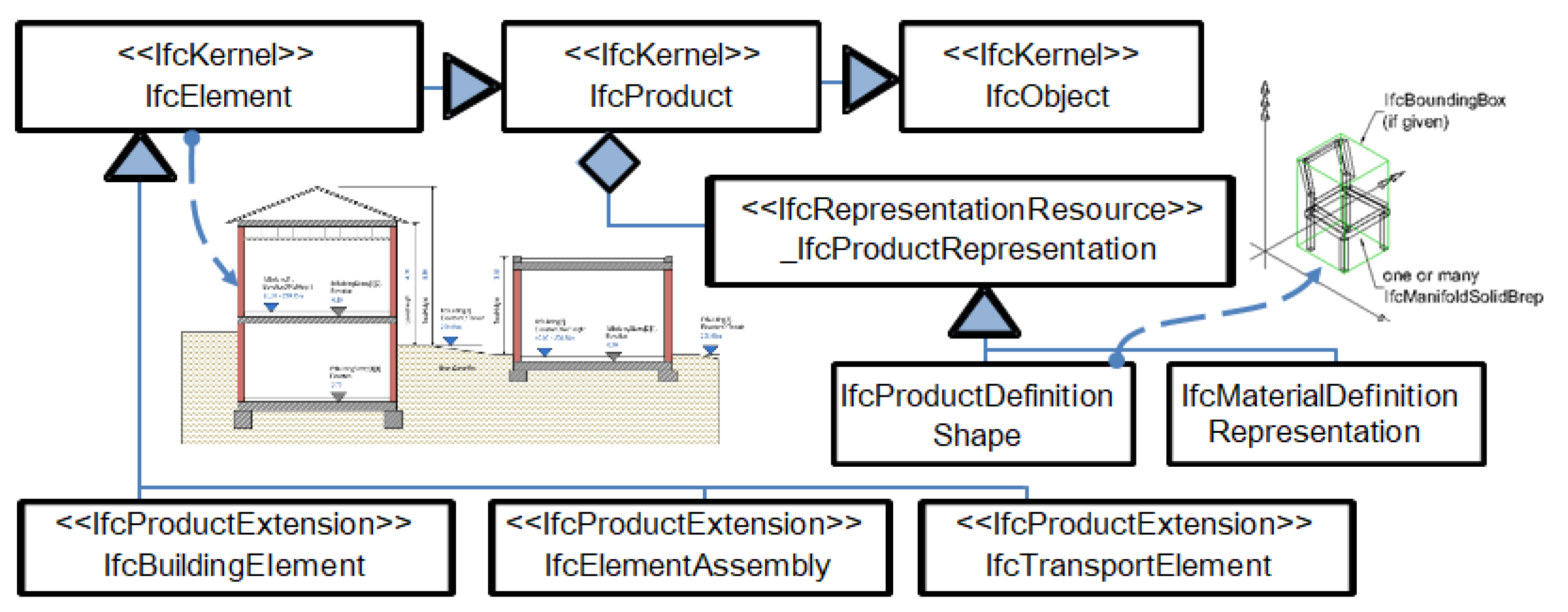
IFC provides the phase information that connects IfcProject to IfcBuildingStorey, thus enabling the search for hierarchically-related information like Figure 2.
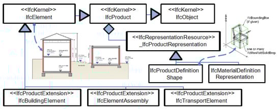
Figure 2.
Major structure expression of IFC (BuildingSmart).
3.3.3. CityGML Standard Model
CityGML is a GIS-based open object information model developed by OGC (Open Geospatial Consortium). It is the ISO TC211 standard and a GML-based application schema that functions as an information interoperation format in city object models. GML based on abstract specification was developed by OGC.
CityGML was developed to more efficiently develop three-dimensional spatial modeling by strengthening models, which GML lacks; it defines materials, features and models, as well as their mutual phase relationships. GML, based on object-based classes, defines the geometry (expressing geometric models), the features (expressing geographic features), and the definition class (defining the material dictionary).
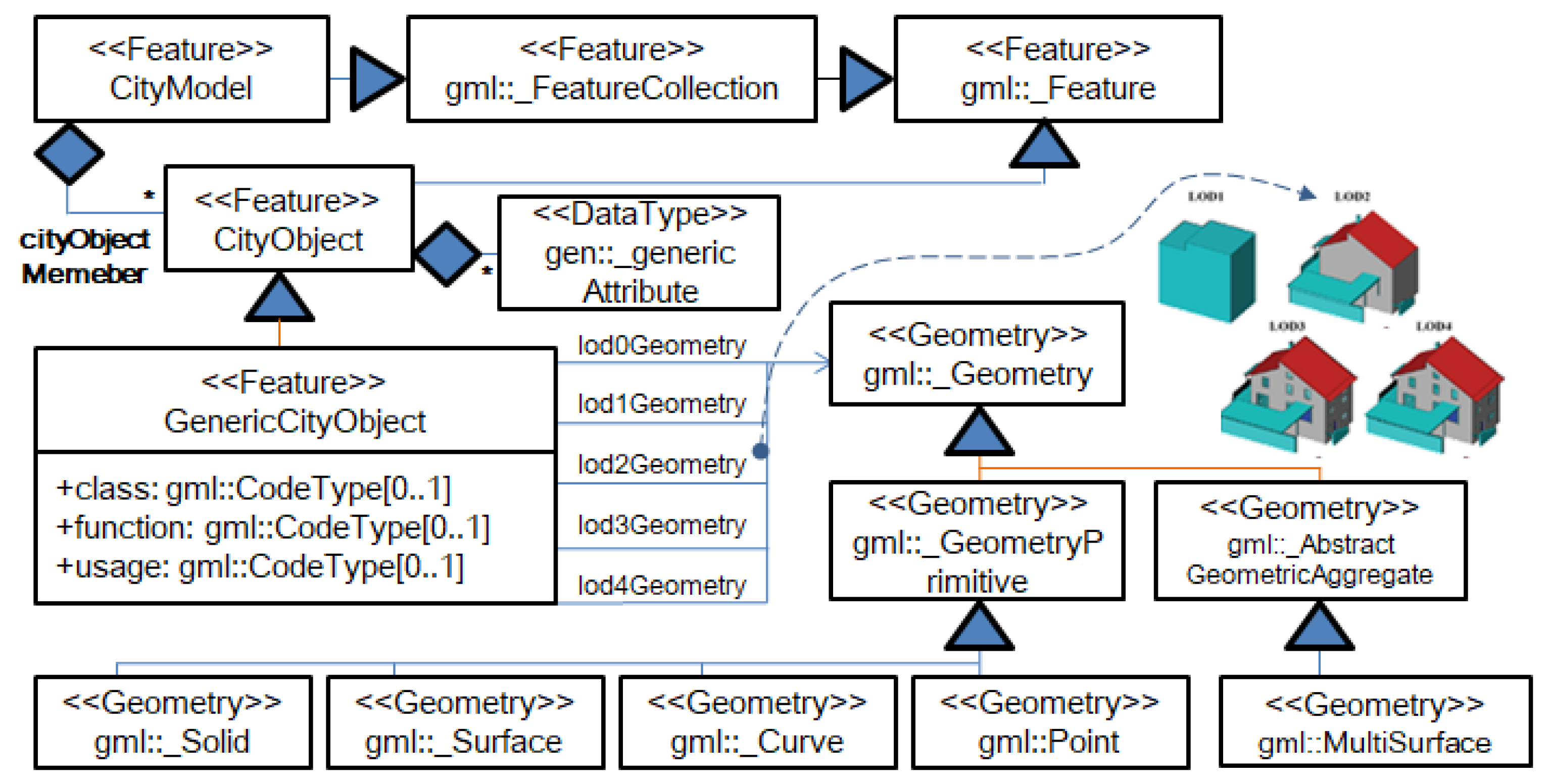
CityGML was developed with a focus on the object information model of city infrastructure. By considering the abstraction and performance of the model, it can express LOD (level of detail) information like Figure 3. CityGML bases its schema hierarchy structure design on features. It uses CityObject, derived from the features, to extend the geographical feature models into facilities, transport means, water resources, terrain, etc.; in order to express these shapes, it extends the geometry. CityModel is provided in order to be able to handle many city objects, and this class is derived from FeatureCollection, where the feature is the basic class [18]. FeatureCollection uses the composite design pattern as an object container so that it can manage many city objects [19]. This serves a role similar to IFC’s relationship with IfcRelContainedInSpatialStructure. To effectively demonstrate many city facilities, CityGML divides the detailed shape expression levels into LOD 0–5. This is significantly different from IFC’s shape expression method. At individual detailed levels, the geometry expression is defined as from lod0Geometry to lod4Geometry. Recently, to resolve the ambiguity of the CityGML LOD, the CityGML 3.0 concept was proposed [20].
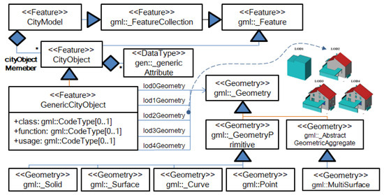
Figure 3.
CityGML LOD model.
3.3.4. Comparison of a Building and the GIS Standard Model
Based on the aforementioned surveyed schema structure, the differences in the application purpose, development method, basic concept, shape definition structure, and LOD were examined. Table 2 outlines the analyzed differences between the IFC and CityGML schemas.
Table 2.
Comparison of the standard schema characteristics between IFC and LandXML.
3.4. B2G Conceptual Mapping
3.4.1. Overview
The BIM-to-GIS conceptual mapping (B2GM) proposed herein focuses on mapping the facility model (including buildings) on the city scale from BIM. To help implement the mapping technology from the ISO standardization perspective, B2GM defines the requirements and logical mapping mechanisms for the physical implementation of heterogeneous data models.
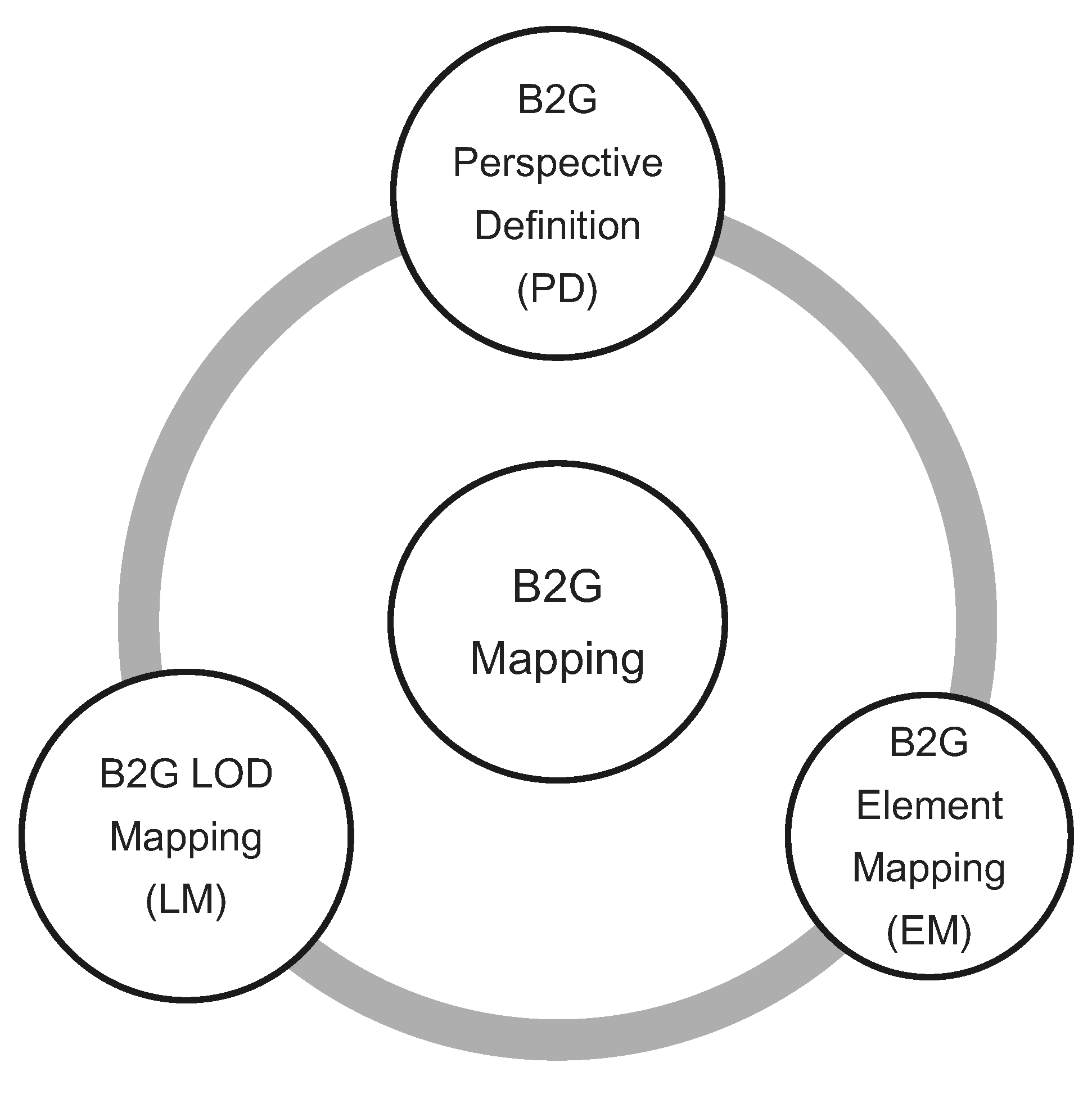
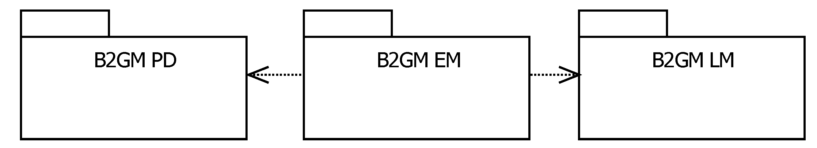
These mechanisms consists of three components that have specific purposes, such as (1) BIM-to-GIS element mapping (B2G EM); (2) BIM-to-GIS LOD mapping (B2G LM); and (3) BIM-to-GIS perspective definition (B2G PD).
- B2G EM supports element mapping from the BIM model to the GIS model. As the BIM model and GIS model schema are different, B2GM EM needs mapping rules determining how to transform from BIM model to a GIS model element.
- B2G LM supports LOD definition and generation from a BIM model to a GIS model. “LOD”, as defined in the GIS model, consists of LODs to represent the geometry information depending on an object in GIS. The LOD models defined a visualization mechanism and classes, which is similar to the concept of B-Rep based on a surface. However, there are no LOD objects in BIM objects in the BIM standard model. To represent BIM object in GIS, LOD information needs to be extracted from the BIM model considering each LOD concept in the GIS model. It can be defined by the LOD mapping rule set.
- B2G PD supports the perspective of information representation depending on the specific use cases, such as the urban facility management (UFM). “Perspective” depends on the use case. For example, when we manage urban facilities, the required data should be collected from the various data sources, including BIM models, and be transformed and presented in a user-specific way. PD defines a data view to extract the needed data and transform the information from the various data sources.
3.4.2. Framework
The B2GM defines the conceptual framework and mechanisms for the mapping of information elements from building information modeling (BIM) to geographic information systems (GIS) in order to access the necessary information based on specific user requirements. The main purpose of B2GM is to define the basic mapping requirement between BIM and GIS, including the external dataset.
B2GM uses existing international standards such as geography markup language (GML) (ISO 19136:2007), CityGML (OGC 12-019) and Industry Foundation Classes (IFC) (ISO 16739:2013).
It is applicable to information query services such as urban facility management operation. BIM object visualization in GIS and other application services that require query processing depending on the relationship between BIM and GIS objects, either in the real or virtual world, will be able to use the mechanisms to map the required information elements between the two systems.
Figure 4 presents a conceptual overview of the B2G mapping and the relationship of the mapping mechanisms.

Figure 4.
B2GM conceptual overview.
It is impossible to perfectly integrate the physical mapping of myriads of BIM and GIS models considering the various actual limitations. Thus, B2GM focuses on providing the concept and method that can conceptually define the information required for BIM-GIS heterogeneous model mapping.
B2GM considers the following:
- Perspective information representation, depending on specific use cases, such as user facility management: “Perspective” depends on the use case to extract the needed data. PD consists of three parts to extract the needed external FM data.
- Element mapping from BIM to the GIS model: As there are differences between the BIM model and the GIS model schema, B2G EM needs the mapping rule to determine the transformation from the BIM to a GIS model element.
- LOD definition and mapping from the BIM to the GIS model: The LOD models define a visualization mechanism. However, there is no LOD concept in BIM objects of the BIM model standard. To represent BIM geometry in GIS, LOD needs to be extracted from the BIM model considering each LOD.
- Connection-oriented approach: For all the elements involved in the mapping, the mapping source is specified. Thus, if the integrated model needs to be renewed, the defined B2GM mechanism can synchronize the data.
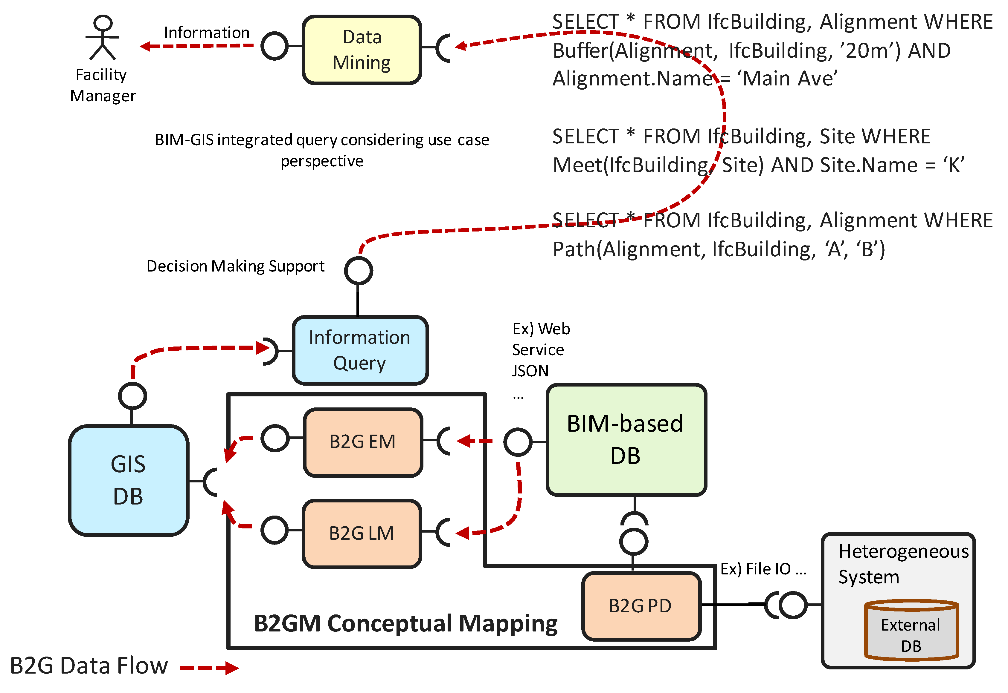
Figure 5 shows the process whereby, using B2GM PD, LM, and EM, the heterogeneous-data models are integrated so that the necessary information can be extracted from a specific use-case perspective.
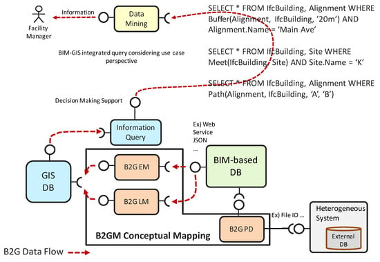
Figure 5.
Database integration and query based on B2GM.
3.4.3. Conceptual Mapping Mechanism
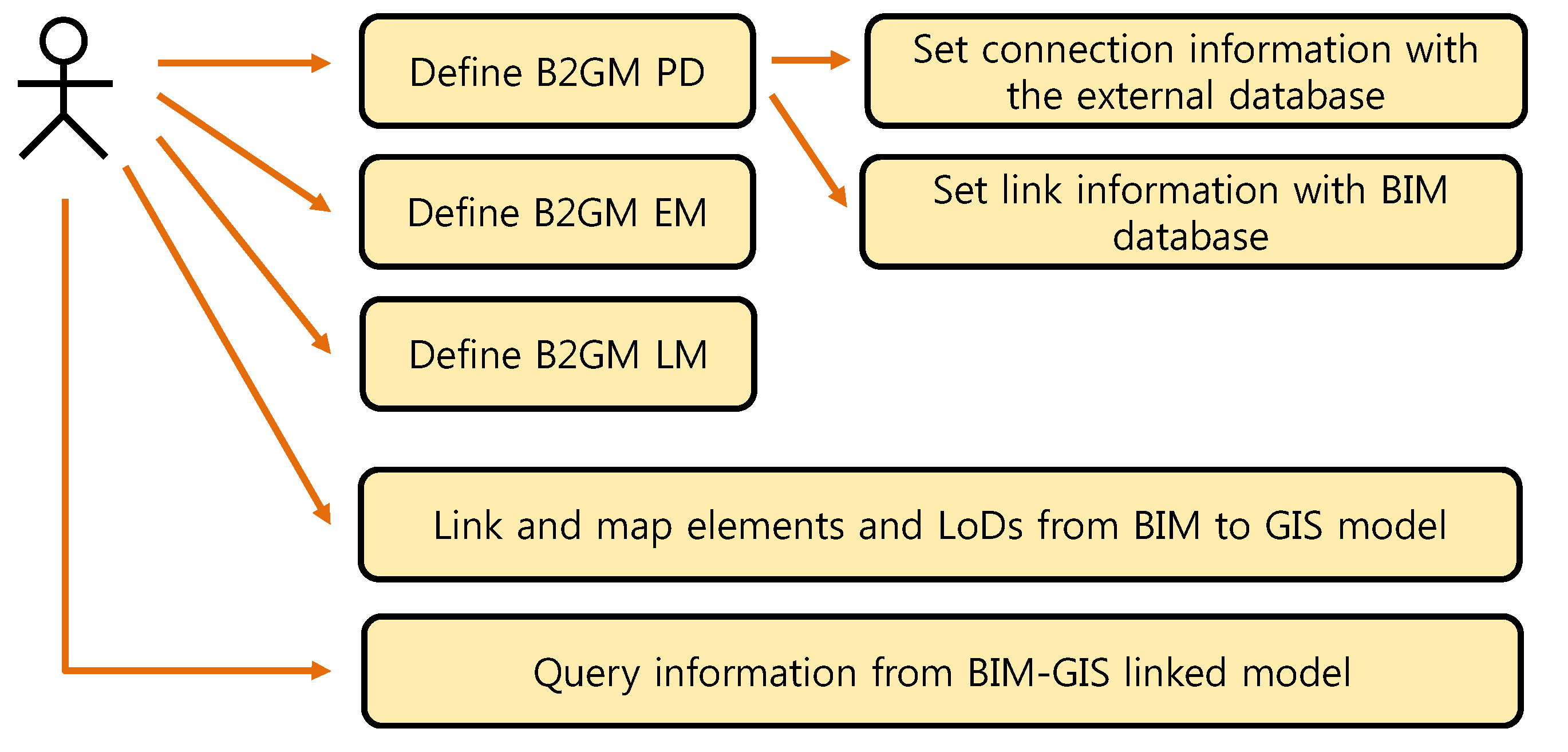
By using the mapping framework, it is possible to query the information from the linked database that utilizes the mapped BIM information. Figure 6 shows use cases for querying information that includes both GIS and BIM information elements from an integrated database.
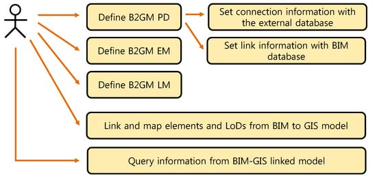
Figure 6.
B2GM use cases.
As mentioned above, it is impossible to define mapping mechanisms considering the myriads of physical BIM and GIS models, and it is also difficult to standardize them. B2GM conceptually defines the mapping requirements; thus, the BIM and GIS models do not need to be generalized.
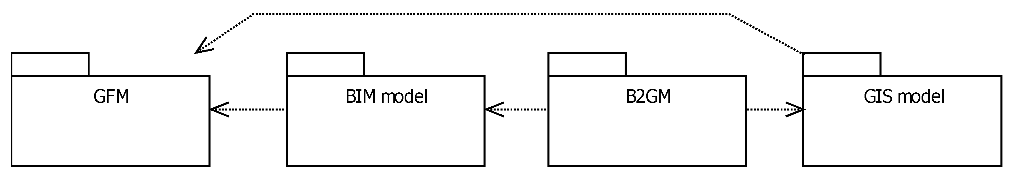
To generalize the BIM and GIS models, the packages were defined as in Figure 7. The geometries of the BIM and GIS models should be able to define the B-rep by referring to GFM (general feature model). The BIM and GIS models, if they meet the package requirements shown in Table 3, can define the B2GM mapping requirements.
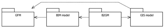
Figure 7.
BIM and GIS concept model and B2GM package diagram.
Table 3.
Package requirements.
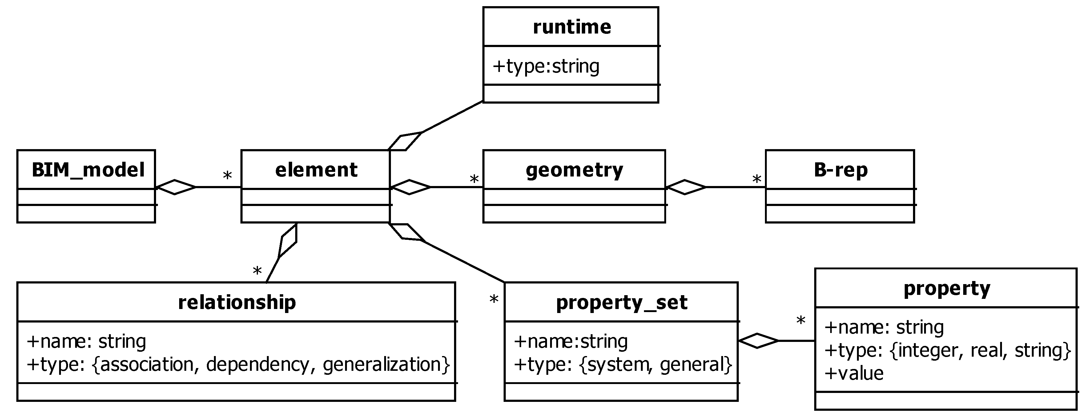
The BIM and GIS model class structures reflecting the requirements described in Table 3 can be expressed as shown in Figure 8 and Figure 9. The B2GM packages have the relationships shown in Figure 10 and Table 4. Each package must meet the requirements described in Table 2 to perform the mapping function.

Figure 8.
BIM DB conceptual model.
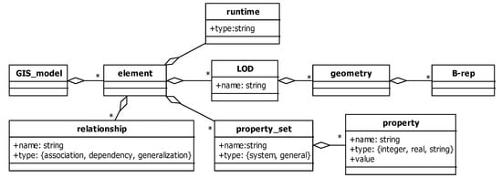
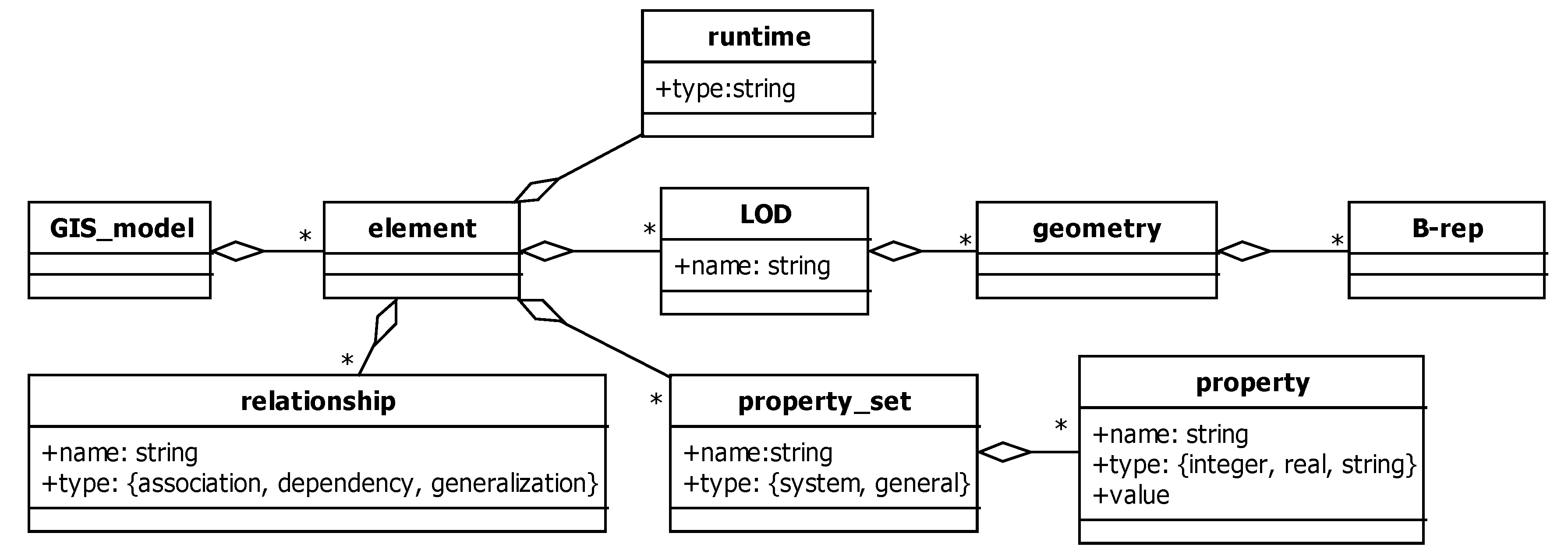
Figure 9.
GIS DB conceptual model.

Figure 10.
GIS DB conceptual model.
Table 4.
B2GM package requirements.
3.5. B2G PD
3.5.1. Overview
B2GM PD supports the method of perspective information representation depending on the specific use cases, such as a facility management (FM). The B2GM PD structure used BPD (BIM perspective definition) from previous related research [21]. BPD research focuses only on the external data mapping required from the BIM perspective. PD is a concept similar to MVD (model view definition) from buildingSMART, but focuses on the definition of the BIM data-binding requirements for mapping BIM into GIS.
To define the information perspective for binding and using BIM, GIS and external data sets such as FM data, B2GM PD includes methods to determine which data is needed for the use-case from the BIM model, how to extract and integrate the data between BIM-GIS and an external data set, and how to represent the integrated information. Each method uses data view, logic view and style view.
3.5.2. Mechanism
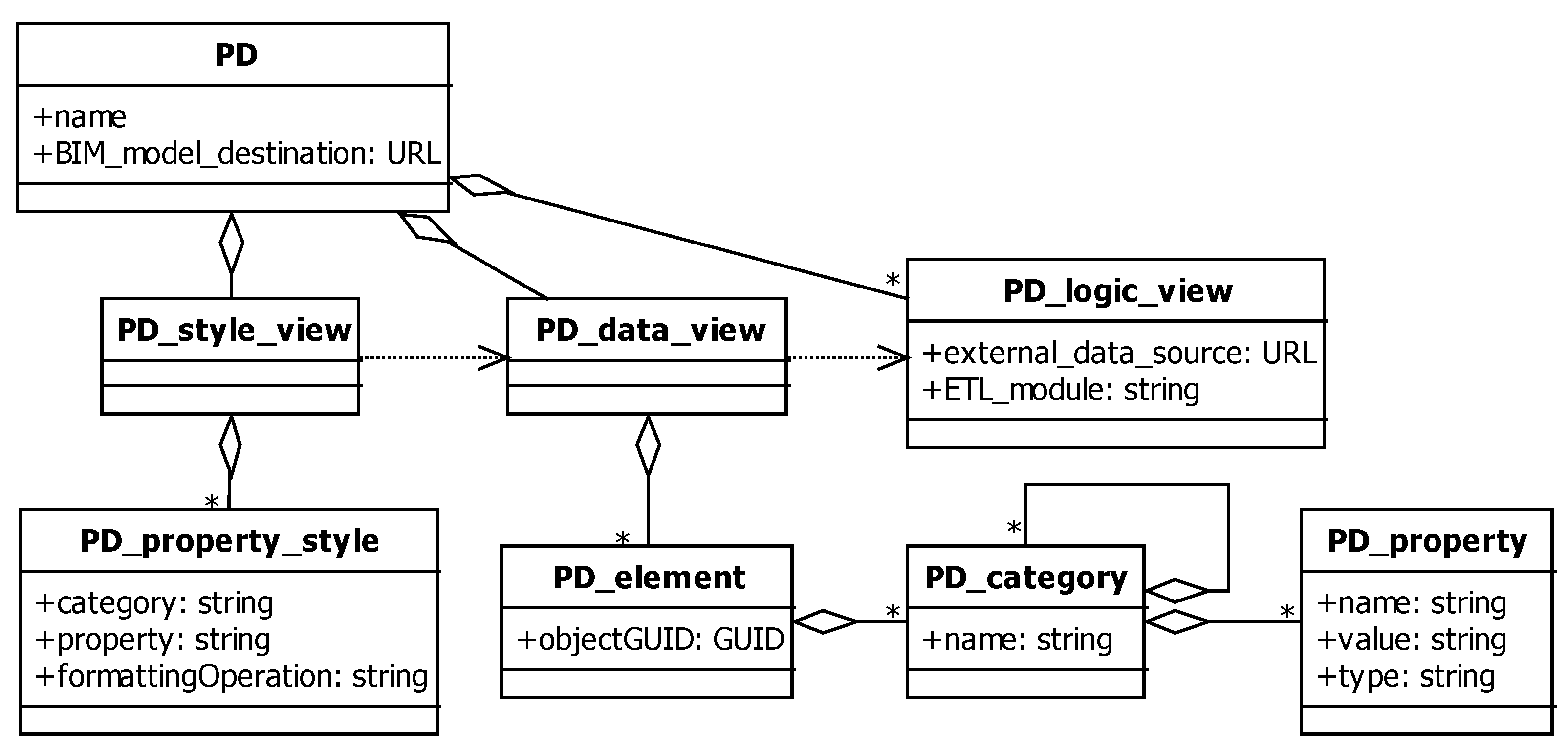
To map the information required from the user perspective into the BIM model, PD should have a BIM model destination in the form of a URL (uniform resource locator). The PD views have been divided into stages of information processing, such as DataView according to perspective, LogicView for information conversion, and StyleView for information expression in order to acquire the information viewed using each perspective.
- Data view: Defines the data view, which expresses the extracted data as BIM object properties. Properties are combined with BIM objects defined with a primary key (PK), such as objectGUID (object globally unique identifier). Properties are expressed by category, name, value, and type. The property to be extracted is formalized into the categories property name, property value, and property type using metadata and scripts. Types are defined as integer, real, and character string.Property = {Category, Name, Value, Type}
- Logic view: As this is the part that extracts and converts data, it is applied using the ETL concept. To process BIM-based FM, the aggregated FM data in the dispersed DB must be extracted, converted, and stored in a form that can be easily used. This process is carried out in the ETL. Through extracting and refining data from various geospatial sources, and converting data and storing it in the DB, the extracted property data can be used to extract or analyze information that supports the perspectives of different project stakeholders. Data must have a defined PK such as objectGUID to be combined with BIM objects.
- Style view: The style view is the formatting method by which the data is displayed on the user interface. Formatting can be expressed in XML form. For instance, it can include a formatting operator designed to convert the data to the unit of measurement required from the user’s perspective.
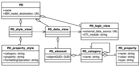
Figure 11.
B2G PD concept diagram (UML).
Table 5.
P2G PD class description.
3.6. B2G EM
3.6.1. Overview
To transform the elements from the BIM model to the GIS model, it is necessary to define the object mapping mechanism in terms of how to transform from BIM to GIS model elements. B2G EM can handle a rule set related to the object mapping mechanism from the viewpoint of specific use cases.
3.6.2. Mechanism
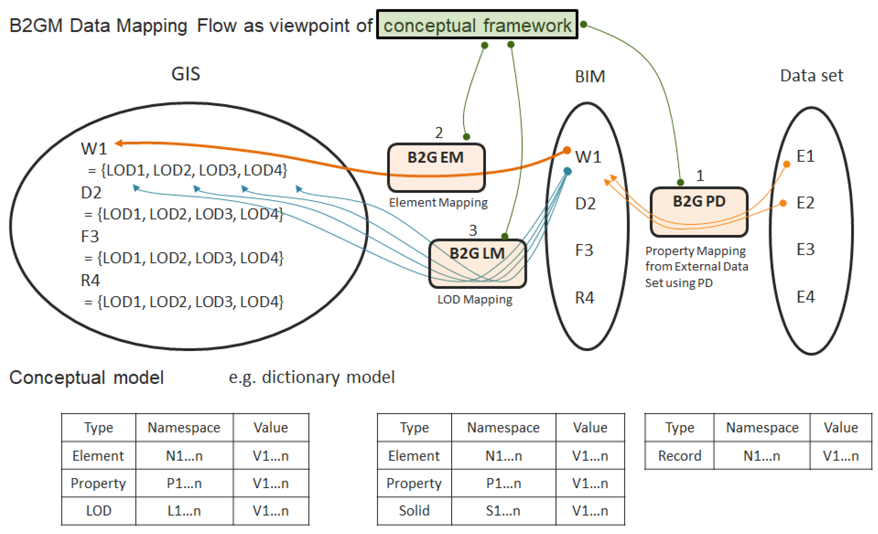
B2G EM defines the rule set related to how to transform from BIM model to GIS model elements such as buildings, floors, walls, windows, etc., as described in Figure 12.
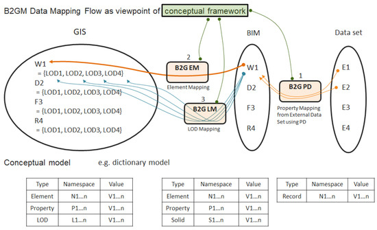
Figure 12.
B2G EM-based element transform concept and relationship between B2GM EM and B2G LM (e.g., dictionary model such as RDBMS).
To implement the transformation of the elements from the BIM model to the GIS model, the LOD mapping method needs to be considered. For example, a wall in BIM DB can be mapped to a wall in LOD2 or LOD3 of a GIS model depending on the specific use-cases. For this reason, it is necessary to consider the method for transforming LODs from the BIM model to the GIS model, which is B2G LM, when we carry out the B2G EM.
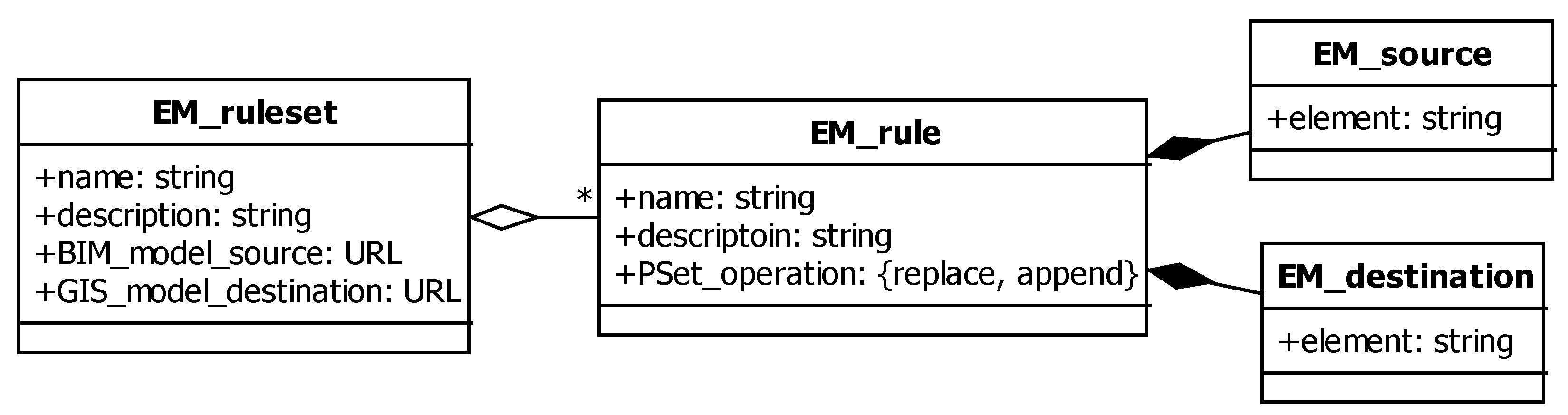
The B2G EM concept can be represented using UML, as shown in Figure 13.
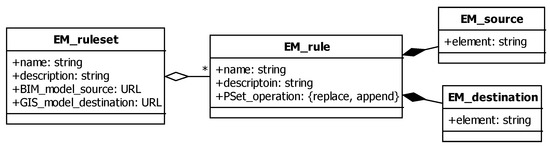
Figure 13.
B2G EM concept diagram (UML).
The mapping source and destination of B2GM EM are defined as URL so that for element attribute data synchronization and source data change it can propagate to the destination, as shown in Figure 14.
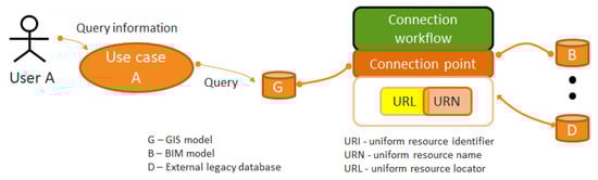
Figure 14.
Information connection approach for element data synchronization, propagation-enabled.
3.7. B2G LM
3.7.1. Overview
B2G LM defines the method for transforming LODs from the BIM to the GIS model. In the GIS model, there is an LOD schema for representing the level of details, which have the purpose of decreasing the information complexity and improving the information visualization performance, such as rendering.
The GIS model LOD schema supports various LODs when representing geometric information, depending on the object on GIS. The LODs defines the visualization mechanism and information, which is similar to the B-Rep structure. However, there is no LOD schema in the BIM model. To represent a BIM object in GIS, the LOD information needs to be extracted from the BIM model. It can be defined by the LOD mapping rule set.
3.7.2. Mechanism
Before mapping the LOD from the BIM to GIS model, we should consider the mechanism that determines how to generate LOD information from the BIM model’s geometry. B2G LM defines the mapping rule to transform LODs from the BIM to the GIS model. In the GIS model, there is LOD schema for representing level of details, which have the purpose of decreasing the information complexity and improving the information visualization performance, such as rendering.
To generate the BIM model LOD, we should define the LOD information to transform it into the LOD of the GIS model element. This LOD information definition method can be a rule set including simple solid operators such as extrusion, projection, etc., such as the B2G LM ruleset operator.
Table 6 shows the operator required for the definition of the B2GM LM ruleset. LOD, extracted from BIM, is created from the perspective of the LOD required for GIS, using the LM ruleset operator in Table 6. Figure 15 shows the class diagram that defines the LOD mapping (LM) rule.
Table 6.
B2G LM rule set operators.
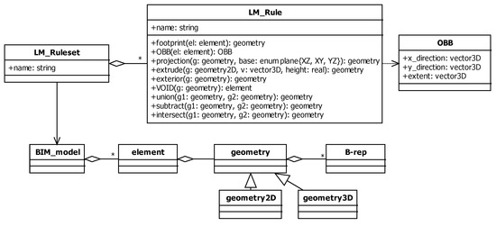
Figure 15.
B2G LM concept diagram (UML).
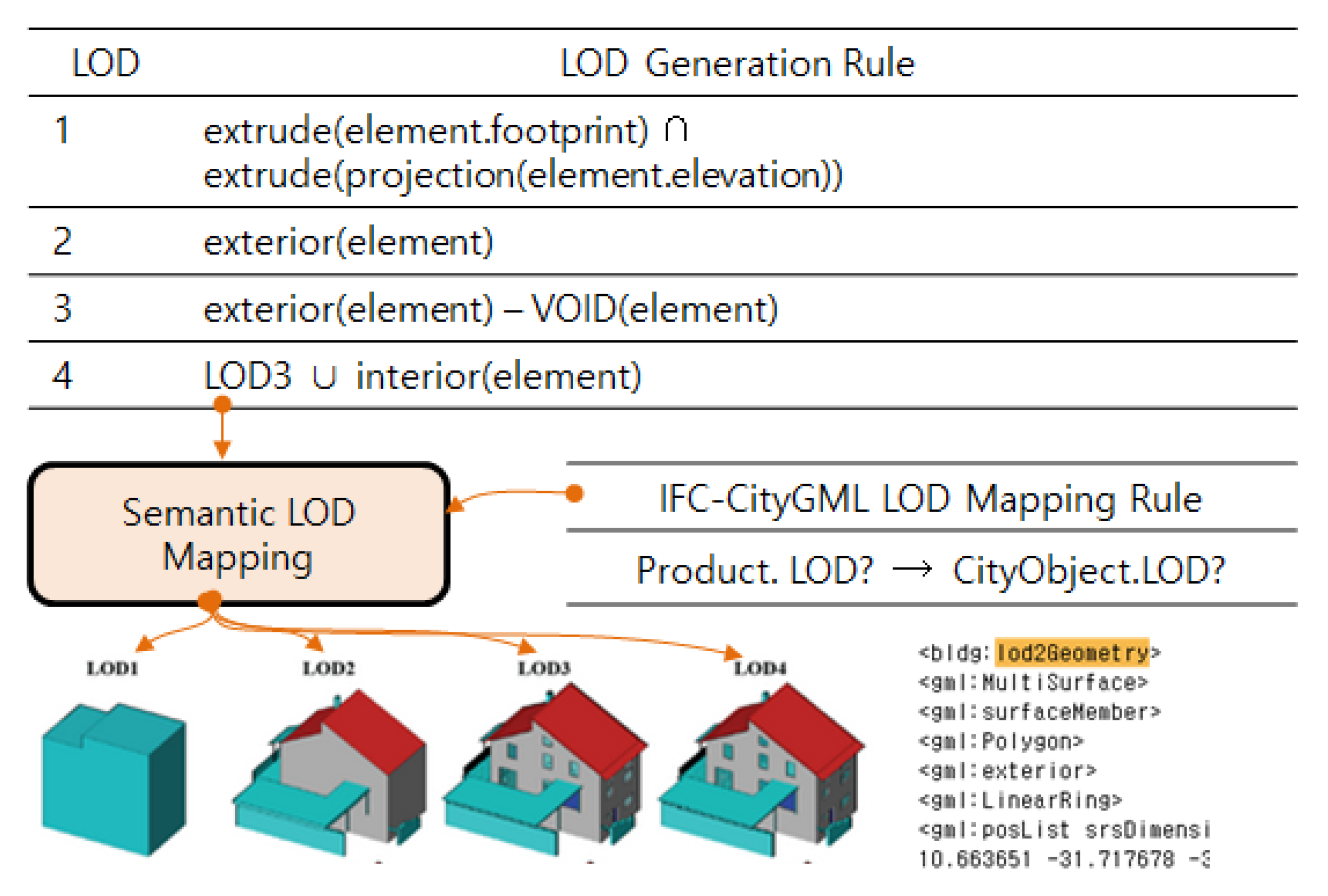
By using the rule set and operators, the method for generating each LODs of the GIS element from the geometric representation of the BIM geometry can be defined.
In example, to define LOD from IFC to CityGML semantically, a set of mapping rules is required. The rule set for B2G LM consists of rules, including operators such as simple solid modelling functions and set operators (union ∪, intersect ∩), as described in Figure 16.
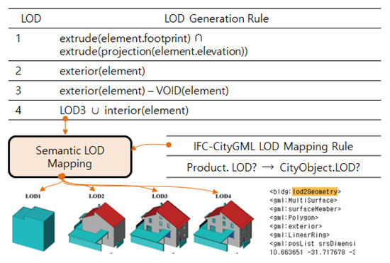
Figure 16.
B2G LM rule set concept.
4. Case Studies and Discussion
B2GM, which supports BIM-GIS model integration, has thus far been described in terms of its concept, structure, and operation mechanism. B2GM is not a perfect solution that supports the integration of heterogeneous models. As mentioned earlier, it is not easy to perfectly map and integrate heterogeneous models, for various reasons. Instead of perfect BIM-GIS integration, it may be practical to define the integration level to make it fit into use-cases before system implementation, and to define the integration mapping mechanism.
Together with the integration requirements considered in B2GM, to derive the BIM-GIS integration level and considerations, the existing BIM-GIS integration solutions were examined in this study in terms of their strengths and weaknesses, and the difference between these and the proposed B2GM [1] was analyzed. Through the survey of previous literature, individual studies were surveyed. This case study targets solutions that support the BIM-GIS linkage or integration method from the platform viewpoint. Thus, the considerations for BIM-GIS integration were also examined.
Table 7 shows a comparison of the BIM-GIS integration solutions thus far studied.
Table 7.
Comparison of the BIM-GIS integration technology characteristics.
The following considerations can be confirmed from the overall research trends and related studies:
C1—The model integration levels may be different according to the use-case. The types of BIM-GIS integration data are varied to support individual BIM-GIS integration solutions. This is because only the data required in the use cases that individual solutions intend to support are integrated.
C2—Inter-model integration can be considered from the lowest level, shape, and model integration to high-level semantic integration.
C3—Model integration entails diverse overhead costs. For instance, the integrated model may cause problems such as heaviness, slow processing, data loss, unnecessary data input, and re-work costs.
C4—Several commercial software solutions involve the model integration process as a black box. It is difficult for the users, however, to guess the data integration process occurring inside a black box, and the corresponding integrated model quality level.
C5—If the heterogeneous-model integration method and process are opened as a white box and can be standardized, they can be constructed and reused as libraries in similar model integration projects. In addition, this can facilitate the checking and management of the quality of the model integration output. If this is not standardized, costs will continue to be incurred to execute the detailed design required for model integration and to implement the solution.
C6—Model integration does not necessarily mean the method of physically combining data at the schema level. For instance, linkage models such as topology manage only the data source references required for model integration, and filter the necessary data used; thus, it can reduce the efforts to ensure data consistency and synchronization between models. Physical model integration does not need to handle this process in the system, thus facilitating data management and utilization, but should handle data consistency and synchronization problems.
B2GM has benefits related to each consideration, as shown in Table 8.
Table 8.
B2GM benefits and solutions related to consideration.
The heterogeneous-model integration level should be able to be defined on a use-case-driven basis. High-level model integration, unnecessary for use-cases, may entail unnecessary costs and cause unnecessary problems. For instance, If BIM-GIS integration is required for the development of spatial-information services for the operation of a smart city, the integration level should be defined in the requirements before the integration process is executed. Before implementing the integrated model output, the user should be able to forecast it and to inspect the quality not only of the model integration output but also of the integration process.
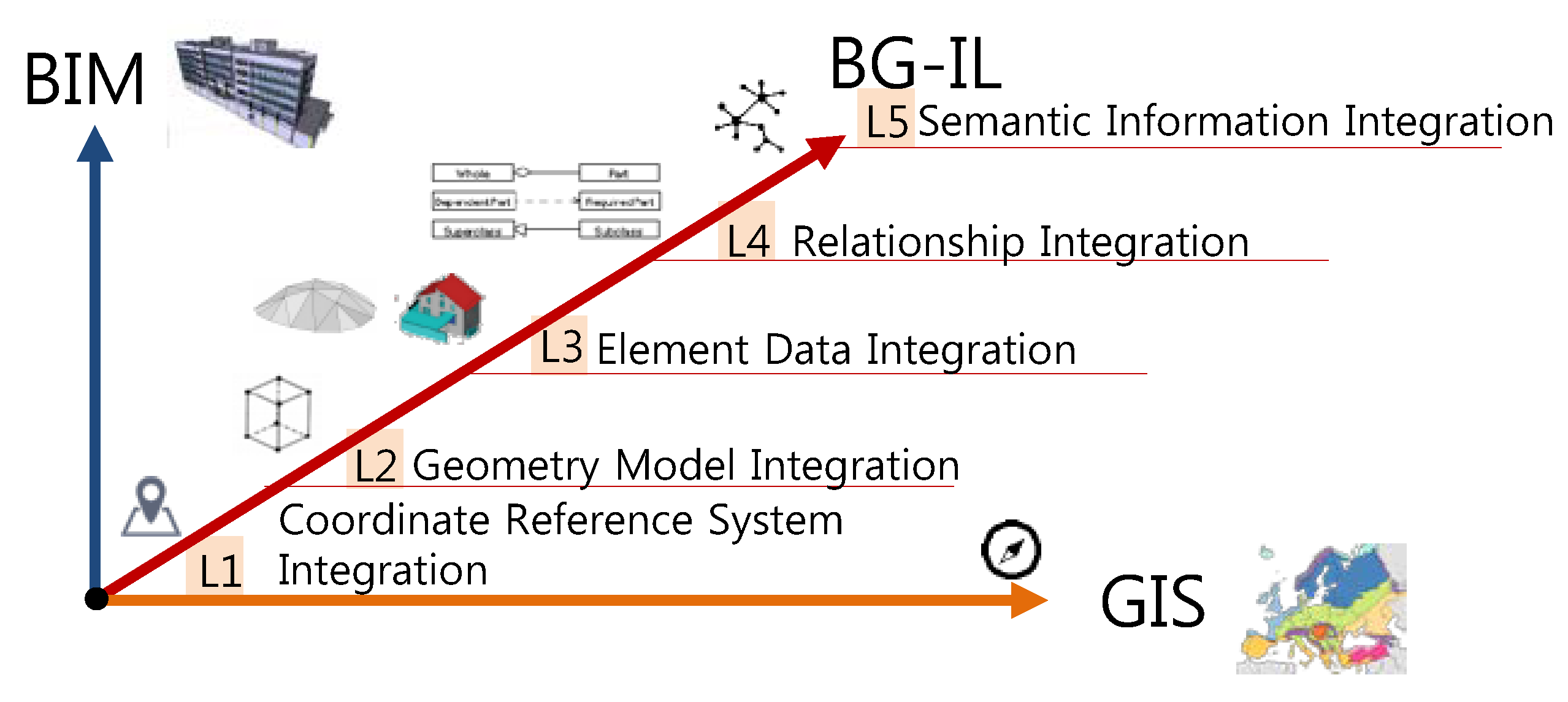
From this perspective, the following illustrates the BG-IL (BIM-GIS integration level) division.
In BG-IL, the upper level must include the lower level. For instance, in urban facility management use cases, the facility management history attribute is more important than the shape information, as only certain cases may require shape information. In this case, efforts to integrate the shape information are not necessarily needed. Figure 17 shows the BG-IL expression, and Table 9 shows examples of implementable use cases according to BG-IL.
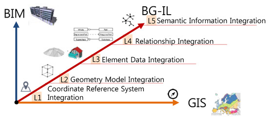
Figure 17.
B2G LM rule set and concept.
Table 9.
BG-IL definition.
Table 10 shows the use-cases available in BG-IL, but there may be a large deviation in the requirements for the information required between the use-cases at each level. For instance, the corresponding related historical information is needed to analyze and manage the facility energy. With only the basic attributes of building elements (e.g., name, area, volume, boundaries, etc.), such use-cases cannot be implemented.
Table 10.
BG-IL use-case examples.
BG-IL does not mean the completeness of model integration. As mentioned, the level of integration should be properly defined according to the use-case perspective. In some use-cases, element data integration may be more important than geometry and coordinate reference system integration. For example, in applications such as facility management, attribute information is more important than geometry information.
To check the level of integration, the reference cases in Table 7 were analyzed. For the analysis, 34 practitioners with BIM or GIS experience for more than five years were interviewed. The interviewed occupations were city, architecture and maintenance.
As the results show, most solutions related to the cases have a lower level of relationship and semantic integration. In general, relationship and semantic integration are more difficult than coordinate system and geometry integration.
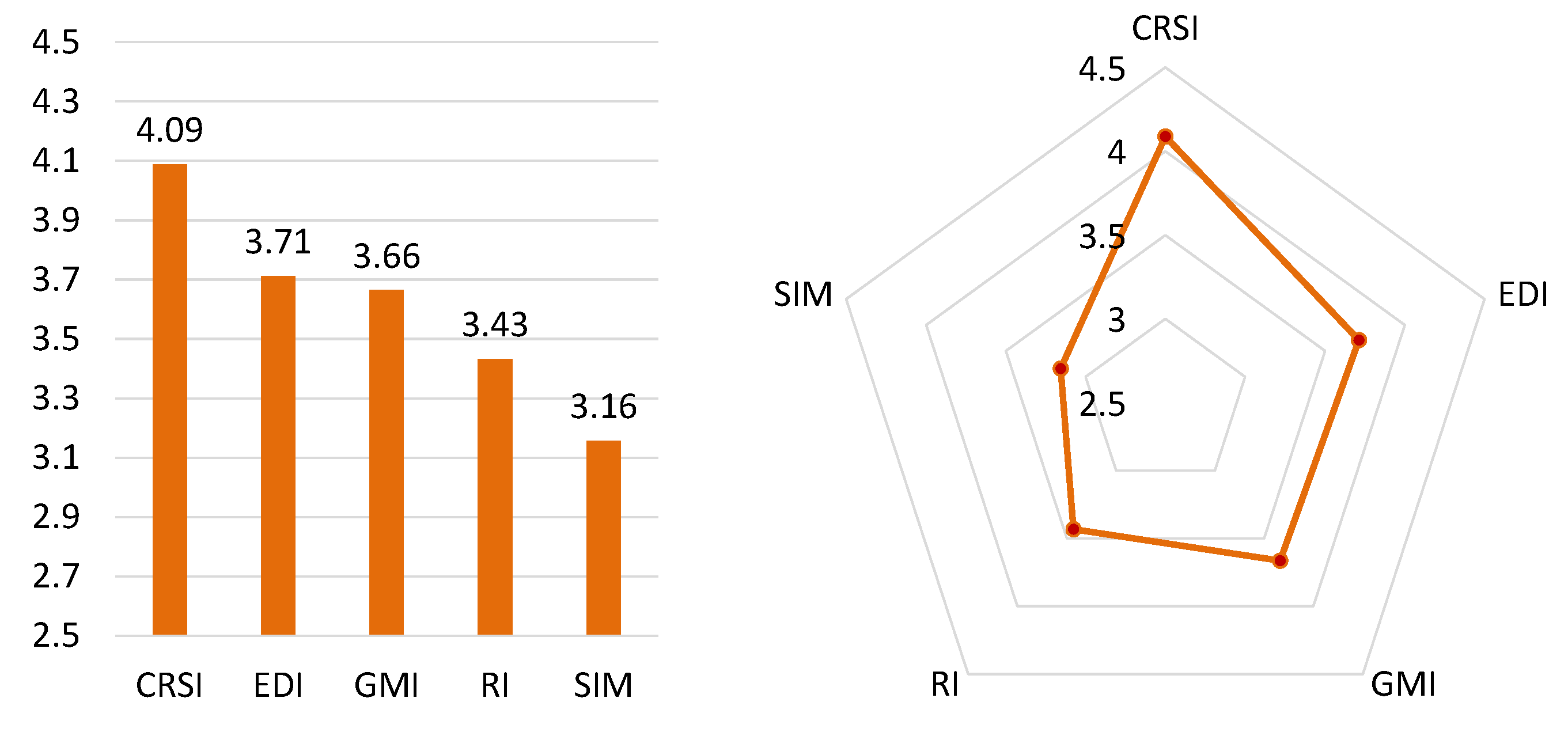
This is because the relationship and semantics have a great deal of variability depending on the use perspective. Developing an integrated model that can represent all use perspectives is very difficult. This is why semantic integration is defined as the highest level of integration. Also, this result shows that the BIM-GIS integrated model use case is still biased toward a specific purpose. In addition, the effects on B2GM was also investigated. The participants in the interview responded that B2GM was beneficial in the order of LoD, element, legacy data, and use perspective integration. However, respondents are expected to benefit from data integration similar to the results in Figure 18.
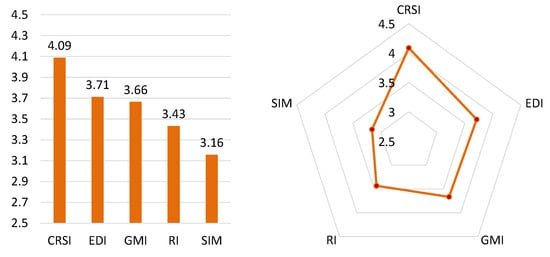
Figure 18.
BIM-GIS model integration level survey results.
Another aspect of the results can mean that users are exploring how to use the BIM-GIS integration model, or that the focus of the use case is one-sided due to the lack of integration level. Standards organizations such as ISO/TC211 will discuss these issues regarding BIM-GIS integration method development, such as B2GM.
5. Conclusions
Decision-making based on BIM-GIM use-cases such as smart city services and city integration models is becoming increasingly important. This study proposes a method designed to clearly define the BIM-GIS integration process. The unclear integration of different-types of model methods may cause the user to hesitate to use the outputs of integration. B2GM defines the integration conditions and processes between different-type models using a formal method, so as to create a white box. This approach helps the user to check that nothing has been omitted before using the integrated model. In addition, the possibility can be reduced that the object information required for the execution of the use-cases may not be obtained or that wrong services may be executed due to noise.
To handle the problems surrounding the integration of BIM (building information modeling) and GIS (geographic information system) heterogeneous models, the relevant research trends were surveyed and their characteristics were analyzed. The methods of schema integration, extension, linkage, etc. have their respective limitations, and it is not easy to integrate heterogeneous models. According to the use-case, the necessary model integration levels and procedures may vary. BIM-GIS conceptual mapping (B2GM), instead of integrating heterogeneous model schemas, attempts to standardize the BIM-GIS model integration process to make it fit the user’s requirements from the use-case perspective. B2GM divides the heterogeneous process into PD, EM, and LM, and links and maps BIM models on the city scale.
The case analysis and discussion analyzed the research trends, derived considerations for heterogeneous-model integration based on the experience gained from the B2GM research, and defined the integration level (i.e., BG-IL). In addition, examples of applicable use-cases according to the integration level were presented. It was thus confirmed that clearer model integration goals and strategies need to be derived.
In the future, considering the insights obtained from this study, research will be conducted on a method of clearly describing the BIM-GIS model integration levels and information used. It is thus expected that the model integration levels and level of detail (LOD) of the integrated output at the requirement definition level will be clearly described, and that the quality of information models can be properly managed.
Acknowledgments
This research was supported by a grant (18AUDP-B127891-02) from the Architecture & Urban Development Research Program funded by the Ministry of Land, Infrastructure and Transport of the Korean government.
Conflicts of Interest
The authors declare no conflicts of interest.
References
- International Organization for Standardization. ISO/AWI 19166 Geographic Information—BIM to GIS Conceptual Mapping (B2GM); ISO TC211; International Organization for Standardization: Geneva, Switzerland, 2016. [Google Scholar]
- Karan, E.P.; Irizarry, J. Developing a spatial data framework for facility management supply chains. In Construction Research Congress 2014@, Construction in a Global Network; ASCE: Reston, VA, USA, 2014; pp. 2355–2364. [Google Scholar]
- Beetz, J.; Coebergh, W.; Botter, R.; Zlatanova, S.; De Laat, R. Interoperable data models for infrastructural artefacts—A novel IFC extension method using RDF vocabularies exemplified with quay wall structures for harbors. In eWork and eBusiness in Architecture, Engineering and Construction; CRC Press: Boca Raton, FL, USA, 2014; p. 354. [Google Scholar]
- Cruz, I.F.; Sunna, W.; Chaudhry, A. Semi-automatic ontology alignment for geospatial data integration. In Geographic Information Science; Springer: Berlin/Heidelberg, Germany, 2004; pp. 51–66. [Google Scholar]
- Peachavanish, R.; Karimi, H.A.; Akinci, B.; Boukamp, F. An ontological engineering approach for integrating CAD and GIS in support of infrastructure management. Adv. Eng. Inform. 2006, 20, 71–88. [Google Scholar] [CrossRef]
- Hor, A.H.; Jadidi, A.; Sohn, G. BIM-GIS integrated geospatial information model using semantic web and RDF graphs. ISPRS Ann. Photogramm. Remote Sens. Spat. Inf. Sci. 2016, 3, 73. [Google Scholar] [CrossRef]
- The Web Site for City GML: An Information Model for Exchange and Storage of Virtual 3D City Models. 2006. Available online: http://www.citygml.org/ (accessed on 24 April 2018).
- Hagedorn, B.; Döllner, J. High-Level Web Service for 3D Building Information Visualization and Analysis. In Proceedings of the 15th Annual ACM International Symposium on Advances in Geographic Information Systems, Seattle, WA, USA, 7–9 November 2007; p. 8. [Google Scholar]
- Nour, M. Manipulating IFC Sub-models in Collaborative Teamwork Environments. In Proceedings of the 24th CIB W-78 Conference on Information Technology in Construction, Maribor, Slovenia, 27–29 June 2007. [Google Scholar]
- Li, Y. Development Architecture for Industrial Data Management; KTH Royal Institute of Technology: Stockholm, Sweden, 2013. [Google Scholar]
- Scherer, R.J. Product-model-based Collaboration. In Proceedings of the 24th CIB W78 Conference, Maribor, Slovenia, 27–29 June 2007. [Google Scholar]
- Schaller, J.; Gnaedinger, J.; Reith, L.; Freller, S.; Mattos, C. GeoDesign: Concept for Integration of BIM and GIS in Landscape Planning. J. Digit. Landsc. Archit. 2017, 2, 102–112. [Google Scholar]
- El-Mekawy, M.; Östman, A.; Hijazi, I. An evaluation of IFC-CityGML unidirectional conversion. Int. J. Adv. Comput. Sci. Appl. 2012, 3, 159–171. [Google Scholar] [CrossRef]
- Sebastian, R.; Böhms, M.; Van den Helm, P. BIM and GIS for Low-Disturbance Construction. In Proceedings of the 13th International Conference on Construction Applications of Virtual Reality, London, UK, 30–31 October 2013. [Google Scholar]
- Isikdag, U.; Underwood, J.; Aouad, G. An investigation into the applicability of building information models in a geospatial environment in support of site selection and fire response management processes. Adv. Eng. Inform. 2008, 22, 504–519. [Google Scholar] [CrossRef]
- Pickard, R. ArcView Shape Files: A Read/Write OCX, Help File. 2004. Available online: http://arcscripts.esri.com/details.asp?dbid=11810/ (accessed on 24 April 2018).
- Amirebrahimi, S.; Rajabifard, A.; Mendis, P.; Ngo, T. A data model for integrating GIS and BIM for assessment and 3D visualisation of flood damage to a building. Locate 2015, 15, 10–12. [Google Scholar]
- Open Geospatial Consortium. Available online: https://www.citygml.org/files/CityGML_2_0_0_UML_diagrams.pdf (accessed on 24 April 2018).
- Johnson, R.; Vlissides, J.; Helm, R.; Gamma, E. Design Patterns: Elements of Reusable Object-Oriented Software; Pearson Education; Addison-Wesley: Boston, MA, USA, 1994. [Google Scholar]
- Löwner, M.-O.; Gröger, G.; Benner, J.; Biljecki, F.; Nagel, C. Proposal for a new LOD and multi-representation concept for CityGML. Remote Sens. Spat. Inf. Sci. 2016, 4, 3–13. [Google Scholar] [CrossRef]
- Kang, T.W.; Choi, H.S. BIM perspective definition metadata for interworking facility management data. Adv. Eng. Inform. 2015, 29, 958–970. [Google Scholar] [CrossRef]
- Kang, T.W.; Hong, C.H. A study on software architecture for effective BIM/GIS-based facility management data integration. Autom. Constr. 2015, 54, 25–38. [Google Scholar] [CrossRef]
- Kang, T.W.; Choi, H.S. BIM-based data mining method considering data integration and function extension. KSCE J. Civ. Eng. 2017, 1–12. [Google Scholar] [CrossRef]
- Dimopoulou, E.; Tsiliakou, E.; Kosti, V.; Floros, G.; Labropoulos, T. November. Investigating integration possibilities between 3D modeling techniques. In Proceedings of the 9th 3DGeoInfo Conference, Dubai, UAE, 11–13 November 2014; pp. 1–16. [Google Scholar]
- Moghadam, S.T.; Lombardi, P.; Mutani, G.; Osello, A.; Ugliotti, F.M. BIM-GIS modelling for sustainable urban development. In Proceedings of the Towards Post-Carbon Cities (SBE16), Turin, Italy, 18–19 February 2016; pp. 18–19. [Google Scholar]
- Kim, H.; Chen, Z.; Cho, C.S.; Moon, H.; Ju, K.; Choi, W. Integration of BIM and GIS: Highway cut and fill earthwork balancing. In Proceedings of the Computing in Civil Engineering, Austin, TX, USA, 21–23 June 2015; pp. 468–474. [Google Scholar]
- Deng, Y.; Cheng, J.C.; Anumba, C. Mapping between BIM and 3D GIS in different levels of detail using schema mediation and instance comparison. Autom. Constr. 2016, 67, 1–21. [Google Scholar] [CrossRef]


© 2018 by the author. Licensee MDPI, Basel, Switzerland. This article is an open access article distributed under the terms and conditions of the Creative Commons Attribution (CC BY) license (http://creativecommons.org/licenses/by/4.0/).