Abstract
Minimally Invasive Surgery (MIS) is one of the main aims of modern medicine. It enables surgery to be performed with a lower number and severity of incisions. Medical robots have been developed worldwide to offer a robotic alternative to traditional medical procedures. New approaches aimed at a substantial decrease of visible scars have been explored, such as Natural Orifice Transluminal Endoscopic Surgery (NOTES). Simple surgical tasks such as the retraction of an organ can be a challenge when performed from narrow access ports. For this reason, there is a continuous need to develop new robotic tools for performing dedicated tasks. This article illustrates the design and testing of a new robotic tool for retraction tasks under vision assistance for NOTES. The retraction robots integrate brushless motors to enable additional degrees of freedom to that provided by magnetic anchoring, thus improving the dexterity of the overall platform. The retraction robot can be easily controlled to reach the target organ and apply a retraction force of up to 1.53 N. Additional degrees of freedom can be used for smooth manipulation and grasping of the organ.
1. Introduction
Surgical procedures have advanced over the past years and many solutions have been proposed with the aim of reducing the invasiveness of current medical techniques [1]. Minimally Invasive Surgery (MIS) provides the same quality of surgery with smaller incisions compared to an open approach, thus reducing trauma for the patient and consequently improving acceptability and cosmetics as well as reducing recovery times. Laparoscopy is currently considered the MIS technique par excellence, and is performed using long instruments that are introduced in the abdomen through dedicated accesses. From a medical viewpoint, laparoscopy requires high skills, due to the intrinsic technical limitations that result in the loss of hand-eye coordination and reduced dexterity.
Robotic surgery has been introduced in the clinical practice to make difficult surgical tasks (i.e., suturing tasks) easier for the surgeon, recovering hand-eye coordination and dexterity. The Da Vinci surgical robot was the first example of medical robot that was successfully applied to the medical practice [2]. Through a dedicated console, the surgeon can intuitively and precisely control the laparoscopic tools, while a stereoscopic 3D camera provides images of the surgical scenario. Despite its unquestionable advantages, the Da Vinci system is bulky, difficult to set up in the operating room and expensive. Above all, the same number of incisions (i.e., the same level of invasiveness) is required for a robotic laparoscopic surgery and a surgery performed in traditional laparoscopy. Other more compact robots have been developed for approaching traditional laparoscopy with a robot, but they still have the major limitation of requiring the same number of incisions as in traditional laparoscopy [3,4,5].
In order to reduce the invasiveness of minimally invasive procedures, Natural Orifice Transluminal Endoscopic Surgery (NOTES) was introduced in 2004 [6]. NOTES has attracted growing interest because it eliminates abdominal incisions in the diagnosis and treatment of abdominal pathologies, by combining endoscopic and surgical techniques. Nowadays, NOTES procedures can be performedclinically using conventional or modified endoscopes [7,8], hence exploiting the flexibility of such instruments for reaching the surgical target from different natural orifices. On the other hand, the main drawbacks are related to their low dexterity, reduced force generation, and poor mechanical stability, thus making the surgical procedure extremely challenging [9]. In order to overcome stability limitations, miniaturized robotic systems have been proposed worldwide, that can be introduced in the body and driven to the surgical target, exploiting magnetic coupling between internal and external magnets [10,11,12]. These robotic platforms have undergone experimental trials on live animals and have shown promising potential to become clinical realities.
Although these solutions allow the successful anchoring of the robotic system to the abdominal wall, the fine control of the Degrees of Freedom (DOFs) has been only partially demonstrated during research studies [13]. For this reason, other robotic systems have been proposed, such as [14,15], in which dedicated miniaturized surgical tools have been proposed to perform basic surgical tasks in NOTES. Other solutions exploit advanced endoscopic robots, such as [16], or dexterous miniature robots with integrated motors [17,18]. As demonstrated in experimental trials on animals, these robotic systems allow tissue manipulation and the performance of simple surgical tasks, but they cannot be used to retract an organ or tissue while manipulating it. Therefore, the retraction task is typically performed through an additional incision to allow triangulation [19]. Several solutions have been proposed and tested on real working scenarios in order to perform retraction tasks by exploiting magnets as in [20,21,22,23,24]. Although the use of magnets improves the stability of the robotic device and allows the retraction of organs, it is generally difficult to accurately steer the internal robot.
In this work, we present the design of a novel miniature modular robot for retraction tasks in MIS. The robot combines the advantages of magnetic anchoring for positioning and anchoring purposes; furthermore it is integrated with motors to enable two active DOFs, thus improving the dexterity of the platform. The design of the robot took inspiration from preliminary works and was optimized to allow its use on bench applications in cooperation with a camera robot already developed [25]. The retraction robot was equipped with a magnetic anchoring system in order to add basic movement functionalities, as described further below.
2. Materials and Method
2.1. Medical Rationale
The role of modern medical practice is moving increasingly closer to the concept of early diagnosis, making it possible to fight diseases at their early stage and to enable minimally invasive surgical approaches when needed. Early diagnosis allows the therapeutic and surgical treatment of diseases, with lower risks and greater chances of successful outcomes. The concept we propose is based on modular robotic units aiming to provide current NOTES with smaller and less complicated devices capable of performing basic surgical tasks on relatively small operating areas (i.e., low forces, small workspace required).
The aim of this work is to identify specific basic tasks that can be usefully performed during NOTES, and to adapt the robotic modules to them. Each robot is provided with specific functionalities that participate in the complete surgery all together. In previous work [25], we proposed the basic design of the modules by describing the development and manufacturing of a camera robot, paving the way to the development of other modules to be used during surgical NOTES procedures.
2.2. Retraction Robot
In this work, we describe another essential module for surgical procedures, which was tested in terms of generated force and possible motion in the surgical scenario.
The retraction robot, having a diameter of 12 mm and a total length of 52 mm including the magnetic base, was designed with a serial kinematic chain, since it can be more easily introduced through a surgical trocar compared to a parallel robot. The diameter and the length of the robot allow introduction through an esophageal access port, as demonstrated in [17]. Since the main goal of the devised task is to retract a tissue to allow its manipulation by another tool (i.e., an endoscope or another robotic unit), we made the technical choice to internally integrate the robot with two motors for one single pitch DOF in addition to the opening/closing mechanisms of the gripper. The retraction robot relies on three additional external DOFs for the correct positioning of the robot in the abdomen, as described further below. Camera and retraction robot 3D sketches are shown in Figure 1.
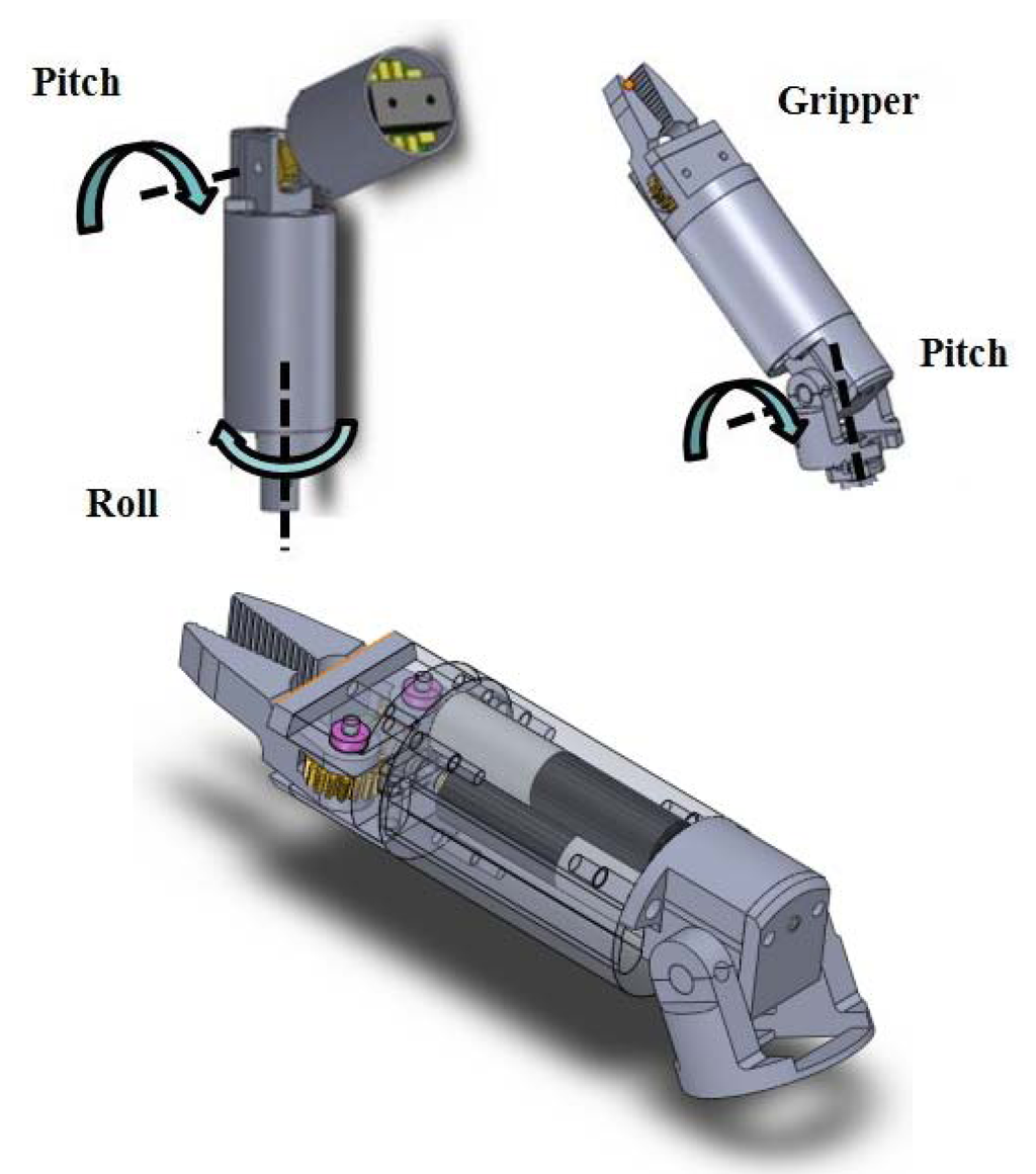
Figure 1.
(Top-Left) 3D sketches of the camera robot and their Degrees of Freedom (DOFs). (Top-Right) 3D sketches of the retraction robot. (Bottom) Detail of the retraction robot and embedded motors.
Brushless micromotors SBL04 (Namiki, Akita, Japan) with 1:337 reduction ratio were selected as actuators for the rotational DOFs, due to the large generated torque (up to 5.7 mNm) compared to the small size (4 mm in diameter and 17.4 mm in length including the gearbox). These motors can be easily controlled in two directions by using commercial boards mounted in a circuit architecture with buttons (for activating one motor) and switches (for choosing the motion direction).
The actuators inside the robot determine the design of the robot itself, since the proximal link motors must withstand a high torque; consequently, a high reduction ratio mechanism must be considered. The design of the mechanisms for the pitch joint consists of a helical gear mounted on a worm gear. This is used to transmit motion between the axis of the motor and the orthogonal pitch joint axis with a high reduction ratio that makes the system non-backdrivable.
The retraction robot has two DOFs: a pitch actuated joint and an end-effector consisting of an opening/closing mechanism for the gripper. Its workspace is thus one-dimensional as its task is to pull the retracted tissue towards the abdominal wall in order to expose the target site. The motion range of the pitch DOF is −180°; 180°. Although the retraction unit only provides 2 internal DOFs, a full tridimensional workspace can be swept by moving the robot magnetically attached to the abdominal wall; the abdominal wall can be also pushed, in order to gain additional mobility due to the magnetic coupling. The assembled retraction robot is shown in Figure 2.
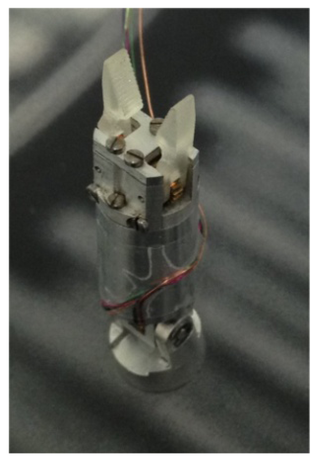
Figure 2.
Assembled prototype of the retraction robot.
2.3. Camera Robot
The camera robot consists of a 2 DOFs robotic unit, conceived to enable vision during NOTES. The camera robot design is based on a roll/pitch module linked to a passive support that holds the vision system.
Vision System
The vision system was integrated in the distal part of the camera robot. It includes a camera, necessary for each MIS technique, and a source of illumination to optimize the lighting conditions in a dark environment, such as the abdominal cavity.
The camera (Misumi Electronics corp., New Taipei City, Taiwan) has a frame rate of 30 fps (frame per second) and resolution of 320 × 240 pixels. It is 10 mm in length and 8.6 mm in diameter and has a power consumption of 100 mA at 3.3 V. These features are compatible with the devised application in terms of frame rate and resolution (they are sufficient for the proposed tasks), dimensions (the camera can be easily integrated in the robotic module) and power supply and consumption (there are no critical energetic constraints because the camera is wire-supplied from an external power source at 3.3 V). Appropriate lighting conditions are guaranteed by a PCB integrating four white LEDs (light emission diodes) by Nichia Corporation. It was properly designed and positioned close to the camera on the same plane in order to avoid artifacts of the image, such as shadows and highlights. Each LED has dimensions of 2 × 1.2 × 1.3 mm3 and a power consumption of 10 mA at 3.3 V. LEDs were dimensioned and integrated on a circular PCB having an external diameter of 12 mm, corresponding to the robot diameter, and an internal diameter of 8.6 mm, corresponding to the camera diameter, thus ensuring stability of the vision system inside the robot which is very important for the quality of the images during video acquisition. The camera sends the video to an external frame grabber that connects the camera with the USB of the PC and sends the images. The video streaming is displayed on the user interface allowing real-time control of the robotic modules.
2.4. Anchoring and Positioning of the Modules
In this work, we describe another essential module for a surgical procedure which was testedin terms of generated force and possible motion in the surgical scenario. The proposed design is inspired from previous work [25], and it was optimized to obtain a basic unit capable of performing retraction tasks.
2.4.1. Anchoring Frame
In order to provide stable adhesion of the camera module to the abdominal wall and guarantee accuracy and precision in surgical tasks, a dedicated anchoring frame was used. The magnetic attraction force between the internal frame and an external hand-held magnetic module was exploited. The anchoring frame was conceived to host, in the future, up to three miniature robots for vision and tissue manipulation. The possibility of docking the camera robot to the anchoring frame has been demonstrated in [26]. While the docking of vision and manipulators modules is essential for enabling a reliable position control of multi-DOFs robots, the two internal DOFs retraction robots do not need to be attached to the same frame. Although the attachment of the retraction robot to the anchoring frame would not represent an issue in terms of technical and medical efforts, this would limit its tissue retraction effectiveness. For this reason, we preferred to directly link this robot to the abdominal wall by using an additional magnet in order to provide additional DOFs. This allows the robot to move in the whole abdominal cavity, thus improving the ability to reach all interested areas by moving the external magnets and pushing/stretching the insufflated abdomen as needed, without any problems for the patient. A possible application of the retraction robot is highlighted by the red circle in Figure 3, where the retraction robot is used for exposing the target point in the gallbladder (black circle), lifting part of the liver and thus allowing operation of the other modules.
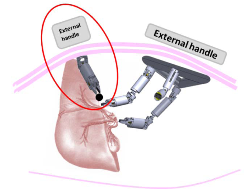
Figure 3.
Possible working scenario of the retraction robots for exposing the gallbladder during Natural Orifice Transluminal Endoscopic Surgery (NOTES) cholecystectomy.
2.4.2. Anchoring and Positioning of the Modules
In order to enable the anchoring and positioning of the retraction robot in the working scenario, a magnetic system was used to attach the robot to the phantom abdominal wall. As the thickness increases, it is sufficient to increase the dimension of the external magnets to have a proper anchoring force. Neodymium-Ferrum-Boron (NdFeB) N52 magnets with diametric magnetization were used as internal and external magnets. The retraction robot was equipped with a cylindrical magnet placed on its base, having dimensions of 9.5 mm in diameter and 6 mm height. This module is anchored tothe abdominal wall through a coupling with a larger cylindrical external magnet (51 mm in diameter and 25 mm height), which can be easily handled by the user to position and orient the retraction robot’s three external DOFs. The external magnets were integrated in plastic handles in order to allow movement of the robotic modules and avoid magnetic attraction between them.
In order to assess whether the magnetic anchoring could effectively hold the retraction robot during basic retraction tasks, magnetic simulation was performed to quantify the attraction force between the internal and external magnets. The magnetic link in the current configuration was simulated with Finite Element Method (FEM) using COMSOL Multiphysics, as shown in Figure 4. In particular, a mesh consisting of 200,000 elements was considered adequate for the devised scenario.
The magnetic attraction force was calculated to support up to 160 g, considering an abdominal wall thickness of 25 mm (i.e., the typical thickness considered for a normal patient). This value is compatible with basic retraction tasks, e.g., in cholecystectomy, the retractor robot could be used for exhibiting the gallbladder or the appendix by retracting part of the liver, while the removal tasks could be performed by using other miniaturized robots. Even if the total weight of the liver can be up to 1.5 kg, the retraction robot is not expected to retract the entire organ, but will be used for exposing the gallbladder.
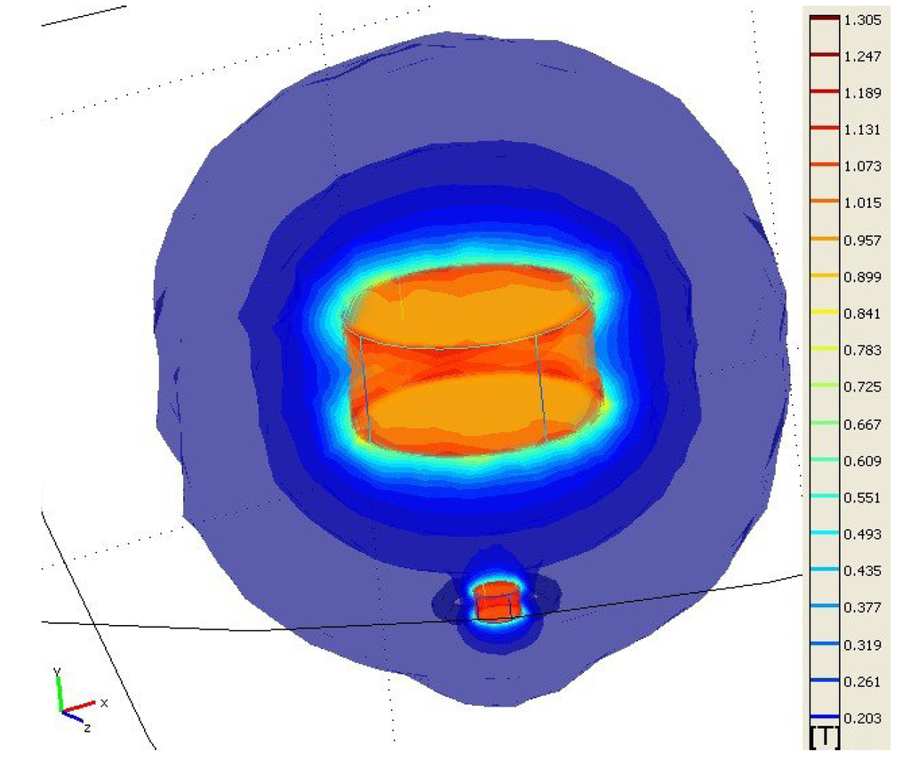
Figure 4.
Finite Element Method (FEM) simulation showing the magnetic flux density (T) for the magnetic anchoring of the retraction robot.
3. Experiment
The aim of this experiment was to demonstrate possible use of the robot for basic grasping and motion tasks by directly observing the real-time video streaming from the camera robot. Quantitative tests were also carried out to characterize the performance of the retraction robot.
Force experiments were performed to evaluate maximum lifting force and gripping force. A commercial six-axis load cell (Nano17, ATI, Industrial Automation, Apex, NC, USA) having a resolution of 3.18 mN was used. The maximum measured lift force was 1.53 N whereas the maximum force of the gripper was 5.3 N. Some snapshots from the experimental session are reported in Figure 5. The weight of the robot (12 g) slightly affects the maximum lift force.
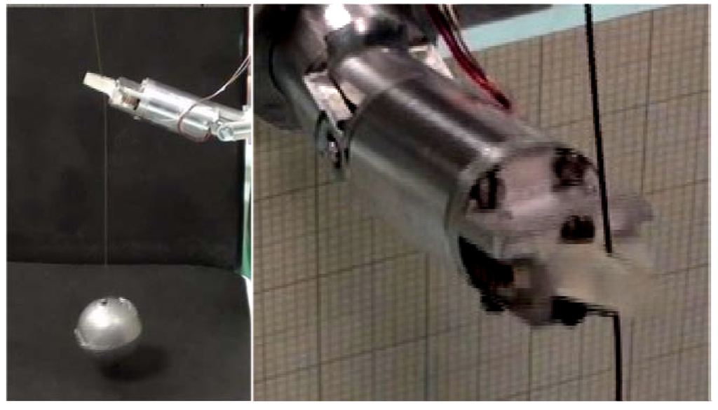
Figure 5.
(Left) Retraction robot during lifting experiments; (Right) Detail of the gripper.
Afterwards, a simulated scenario was set to demonstrate the feasibility of a simple procedure. The procedure consisted of introducing all the robotic components for performing NOTES through an esophageal access port into the abdominal cavity, as in Figure 6. Once all the components were set-up, the retraction robot was used to grasp a tissue under vision assistance provided by the camera robot. The procedure we describe was performed by a user driving the retraction robot and an assistant user following the scene with the camera robot. The activation of both robots was performed by activating the corresponding buttons and switches, in an open loop control closed by the user looking at the real-time video streaming on a PC screen. Once all the components were placed in the abdomen in a starting position, the camera robot was moved in order to frame the retraction robot moving in the direction of a circular target, where a tissue simulator was placed. The retraction robot was then activated in order to grasp the object and release it in a second circular target placed on the other side of the abdomen. The video streaming on the screen allowed the used to steer the retraction robot toward the target in a smooth and intuitive way.
The quantitative tests and the experimental procedure on bench are shown in the companion video.
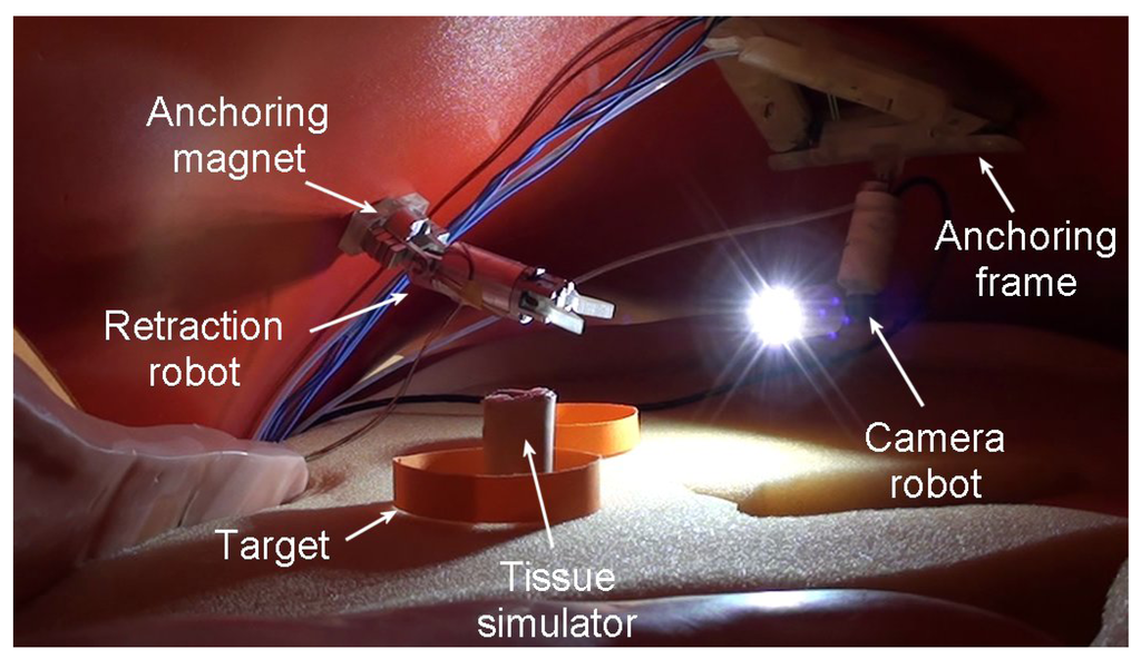
Figure 6.
Simulated abdominal scenario with all the robotic units.
4. Discussion
The design of the retraction robot is a further step in the development of a complete intracavitary robotic platform for dedicated tasks in NOTES. This work has demonstrated the cooperation between two robotic units performing a simple retraction and grasping task.
The camera robot was docked to an anchoring frame following a well-established procedure, while the retraction robot was tested for the first time in a simulated scenario consisting of a human phantom torso. The camera robot was activated to view the entire procedure, while the user was able to move the retraction robot in correspondence of the target to grasp the tissue simulator. After driving the retraction robot toward the final target, the tissue simulator was successfully released. Despite the retraction robot has a low number of internal DOFs, additional mobility can be obtained by actively positioning the robot through the magnetic link.
The camera robot workspace was sufficient to visualize the working area and follow the entire procedure. The retraction robot’s external DOFs were sufficient for positioning the robot close to the target, while the internal DOF and the gripper were able to pitch the object successfully. Force tests were performed to assess the maximum force generated by the retraction robot, which was 1.53 N. The gripping force was also evaluated, showing a maximum grip force of 5.3 N. These force values are compatible with the lifting and grasping of tissues performed to expose organs, as for example the gallbladder during cholecystectomy. The magnetic link between the robot and an external magnet was evaluated by means of FEM simulations, showing the reliability of anchoring for basic retraction tasks. Moreover, in case of practical needs (i.e., for obese patients), the handle can be pushed against the insufflated abdomen so as to enhance the magnetic coupling with the retraction robot. On the other hand, in order to augment the magnetic coupling force, the dimensions of the external magnets can be increased as well. These force values are compatible with other systems commonly used in current NOTES procedures, as reported in Table 1. In addition, the retraction robot introduces additional flexibility thanks to the embedded active DOFs. Moreover, the external handle can be used without problems on the abdomen since it is embedded in a soft case, thus improving safety during the contact with the patient.

Table 1.
Maximum force sustained by different retraction systems [20].
| Retraction System | Main Features | Sustained Force |
|---|---|---|
| Single-channel gastroscope (linear) | clinical tool | 3236 mN |
| Single-channel gastroscope (retroflexed) | clinical tool | 1392 mN |
| Double-channel colonoscope (linear) | clinical tool | 2373 mN |
| Double-channel colonoscope (retroflexed) | clinical tool | 1245 mN |
| Pure magnetic system [20] | research tool, pure magnetic | 882 mN |
| Retraction robot | research tool, magnets for anchoring and embedded motors for internal DOFs | 1530 mN |
It is worth noting that, whenever needed, the retraction robot, in cooperation with an array of robots, can be used as an independent robotic tool for dedicated tasks in NOTES, and is able to perform essential surgical tasks such as manipulation, vision and cutting. The main goal of retraction tasks is to retract an organ in order to expose the underlying tissues and allow another robot to perform dedicated manipulation, as shown in Figure 3. For this reason, we made the choice of integrating two motors to provide basic manipulation and smooth grasping and to provide the robot with a compact size in order to be used in a real scenario.
The workspace is one-dimensional since the only task consists of pulling the retracted tissue towards the abdominal wall in order to expose the target site. The motion range of the pitch DOF is ±180°, while the maximum pulling and grasping forces are 1.53 N and 5.3 N, respectively. The retraction robot reachable workspace can be enhanced thanks to the motion of the external magnetic handle. In fact, thanks to the magnetic link, the retraction robot relies on three additional external DOFs for the correct positioning of the robot in the abdomen. In addition, the handle can be pushed against the insufflated abdomen for the approximation of the target tissue with the robot. Retraction robot and anchoring frame external handles can be used without problems on the abdomen since they are embedded in soft cases that limit magnetic interferences. In a real scenario, both handles will supposedly be held in position by medical assistants, who will move the handles according to the surgeon’s indications.
5. Conclusion
In this paper, the suitability of the retraction robot for NOTES has been successfully demonstrated. With the retraction robot, a specific task of lifting a target object in a simulated scenario, under visual assistance of a camera robot has been performed. The users were able to control the camera robot and the internal and external DOFs of the retraction robot in order to localize an object and move toward the target position. The retraction robot can be indeed considered as a further essential device within the scenario of an array of robots performing dedicated surgical tasks in NOTES. In addition, the retraction robot could be also used as is in the clinical scenario. Future evaluation of the robot in vivo will be performed, once the effectiveness on bench has been successfully demonstrated.
Acknowledgements
This work was supported by the ARAKNES FP7 European Project no. 224565.
Authors Contributions
Arianna Menciassi and Paolo Dario inspired the idea of array of robots for augmenting the kinematic of endocavitary surgery. Giuseppe Tortora defined the scenario including a dedicated robot for retractions tasks for minimally invasive surgery and a camera robot for visualizing images. Giuseppe Tortora and Tommaso Ranzani designed the retraction robot and performed force experiments and simulations. Iris De Falco was involved in the integration of the camera and in the experimental testing of the overall platform. Giuseppe Tortora wrote the paper.
Conflicts of Interest
The authors declare no conflict of interest.
References
- Forgione, A. In vivo microrobots for natural orifice transluminal surgery. Current status and future perspectives. Surg. Oncol. 2009, 18, 121–129. [Google Scholar] [CrossRef]
- Alterovitz, R.; Desai, J.P. Surgical robotics. IEEE Robot. Autom. Mag. 2009, 16, 16–17. [Google Scholar] [CrossRef]
- Lum, M.J.H.; Friedman, D.C.W.; Rosen, J.; Sankaranarayanan, G.; King, H.; Fodero, K., II; Leuschke, R.; Sinanan, M.N.; Hannaford, B. The RAVEN: Design and validation of a telesurgery system. Int. J. Robot. Res. 2009, 28, 1183–1197. [Google Scholar] [CrossRef]
- Yamashita, H.; Iimura, A.; Aoki, E.; Suzuki, T.; Nakazawa, T.; Kobayashi, E.; Hashizume, M.; Sakuma, I.; Dohi, T. Development of endoscopic forceps manipulator using multi-slider linkage mechanisms. In Proceedings of the 1st Asian Symposium on Computer Aided Surgery, Ibaraki, Japan, 28 April 2005.
- Hagn, U.; Konietschke, R.; Tobergte, A.; Nickl, M.; Jörg, S.; Kübler, B.; Passig, G.; Gröger, M.; Fröhlich, F.; Seibold, U.; et al. DLR MiroSurge: A versatile system for research in endoscopic telesurgery. Int. J. Comput. Assist. Radiol. Surg. 2010, 5, 183–193. [Google Scholar]
- Scott, D.J.; Tang, S.J.; Fernandez, R.; Bergs, R.; Goova, M.T.; Zeltser, I.; Kehdy, F.J.; Cadeddu, J.A. Completely transvaginal NOTES cholecystectomy using magnetically anchored instruments. Surg. Endosc. 2007, 21, 2308–2316. [Google Scholar] [CrossRef]
- Yeung, B.P.M.; Gourlay, T. A technical review of flexible endoscopicmultitasking platforms. Int. J. Surg. 2012, 10, 345–354. [Google Scholar] [CrossRef]
- Reavis, K.M.; Melvin, W.S. Advanced endoscopic technologies. Surg. Endosc. 2008, 22, 1533–1546. [Google Scholar] [CrossRef]
- Loeve, A.; Breedveld, P.; Dankelman, J. Scopes too flexible...and too stiff. IEEE Pulse 2010, 1, 26–41. [Google Scholar] [CrossRef]
- Lehman, A.C.; Dumpert, J.; Wood, N.A.; Redden, L.; Visty, A.Q.; Farritor, S.; Varnell, B.; Oleynikov, D. Natural orifice cholecystectomy using a miniature robot. Surg. Endosc. 2009, 23, 260–266. [Google Scholar] [CrossRef]
- Joseph, R.A.; Salas, N.A.; Donovan, M.A.; Reardon, P.R.; Bass, B.L.; Dunkin, B.J. Single-site laparoscopic (SSL) cholecystectomy in human cadavers using a novel percutaneous instrument platform and a magnetic anchoring and guidance system (MAGS): Reestablishing the “critical view”. Surg. Endosc. 2012, 26, 149–153. [Google Scholar] [CrossRef]
- Kobayashi, T.; Gotohda, T.; Tamakawa, K.; Ueda, H.; Kakizoe, T. Magnetic anchor for more effective endoscopic mucosal resection. Jpn. J. Clin. Oncol. 2004, 24, 118–123. [Google Scholar]
- Di Natali, C.; Ranzani, T.; Simi, M.; Menciassi, A.; Valdastri, P. Transabdominal active magnetic linkage for robotic surgery: Concept definition and model assessment. In Proceedings of the IEEE ICRA, St. Paul, MN, USA, 14–18 May 2012.
- Tortora, G.; Salerno, M.; Ranzani, T.; Tognarelli, S.; Dario, P.; Menciassi, A. A modular magnetic platform for natural orifice transluminal endoscopic surgery. In Proceedings of Engineering in Medicine and Biology Society conference (EMBC), Osaka, Japan, 3–7 July 2013.
- Tortora, G.; Dario, P.; Menciassi, A. Array of robots augmenting the kinematics of endocavitary surgery. IEEE/ASME Trans. Mechatron. 2014. [Google Scholar] [CrossRef]
- Abbott, D.J.; Becke, C.; Rothstein, R.I.; Peine, W.J. Design of an endoluminal NOTES robotic system. In Proceedings of the IROS, San Diego, CA, USA, 29 October–2 November2007.
- Lehman, A.C.; Wood, N.A.; Farritor, S.; Goede, M.R.; Oleynikov, D. Dexterous miniature robot for advanced minimally invasive surgery. Surg. Endosc. 2011, 25, 119–123. [Google Scholar] [CrossRef]
- Phee, S.J.; Kencana, A.P.; Huynh, V.A.; Sun, Z.L.; Low, S.C.; Yang, K.; Lomanto, D.; Ho, K.Y. Design of a master and slave transluminal endoscopic robot for natural orifice transluminal endoscopic surgery. J. Mech. Eng. Sci. 2010, 224, 1495–1503. [Google Scholar] [CrossRef]
- Dominguez, G.; Durand, L.; de Rosa, J.; Danguise, E.; Arozamena, C.; Ferraina, P.A. Retraction and triangulation with neodymium magnetic forceps for single-port laparoscopic cholecystectomy. Surg. Endosc. 2009, 23, 1660–1666. [Google Scholar] [CrossRef]
- Ryou, M.; Thompson, C.C. Magnetic retraction in natural-orifice transluminal endoscopic surgery (NOTES): Addressing the problem of traction and countertraction. Endoscopy 2009, 41, 143–148. [Google Scholar] [CrossRef]
- Park, P.O.; Bergstrom, M.; Ikeda, K. Experimental studies oftransgastric gallbladder surgery cholecystectomyand cholecystogastric anastomosis (videos). Gastrointest. Endosc. 2005, 61, 601–606. [Google Scholar] [CrossRef]
- Kume, M.; Miyazawa, H.; Abe, F.; Iwasaki, W.; Uchinami, H.; Shibata, S.; Sato, T.; Yamamoto, Y. A newly designed magnet-retracting forceps for laparoscopic cholecystectomy in a swine model. Minim. Invasive Ther. Allied Technol. 2008, 17, 251–254. [Google Scholar] [CrossRef]
- Steinemann, D.C.; Limani, P.; Clavien, P.A.; Breitenstein, S. Internal retraction in single-port laparoscopic cholecystectomy: Initial experience and learning curve. Minim. Invasive Ther.Allied Technol. 2013, 22, 171–176. [Google Scholar] [CrossRef]
- Cho, Y.B.; Park, C.M.; Chun, H.K.; Yi, L.J.; Park, J.H.; Yun, S.H.; Kim, H.C.; Lee, W.Y. Transvaginal endoscopic cholecystectomy using a simple magnetic traction system. Minim. Invasive Ther. Allied Technol. 2011, 20, 174–178. [Google Scholar]
- Tortora, G.; Dimitracopoulos, A.; Valdastri, P.; Menciassi, A.; Dario, P. Design of miniature modular in vivo robots for dedicated tasks in minimally invasive surgery. In Proceedings of the AIM, Budapest, Hungary, 3–7 July 2011.
- Tognarelli, S.; Salerno, M.; Tortora, G.; Quaglia, C.; Dario, P.; Menciassi, A. An endoluminal robotic platform for Minimally Invasive Surgery. In Proceedings of the IEEE RAS/EMBS BioRob Conference, Rome, Italy, 24–27 June 2012.
© 2014 by the authors; licensee MDPI, Basel, Switzerland. This article is an open access article distributed under the terms and conditions of the Creative Commons Attribution license (http://creativecommons.org/licenses/by/3.0/).