Abstract
The recent global pandemic has posed unprecedented challenges to public health systems and has highlighted the critical need for effective, contactless disinfection strategies in shared environments. This study investigates the use of autonomous robotics to enhance disinfection efficiency and safety in public spaces through the development of a custom-built mobile spraying platform. The proposed robotic system is equipped with an integrated 3D object pose estimation framework that fuses RGB-based object detection with point cloud segmentation to accurately identify and localize high-contact surfaces. To facilitate autonomous operation, both local and global motion planning algorithms are implemented, enabling the robot to navigate complex environments and execute disinfection tasks with minimal human intervention. Experimental results demonstrate the feasibility of the proposed disinfection robotic system.
1. Introduction
The COVID-19 pandemic, which claimed the lives of millions worldwide [1], highlighted the critical importance of effective disinfection in preventing disease transmission. While the pandemic has subsided, the need for regular and efficient disinfection remains essential in a wide range of public environments, such as hotels, offices, transport hubs, and other high-traffic areas. Pathogens can spread through respiratory droplets or via contact with contaminated surfaces [2], where one infected individual touching a surface can indirectly transmit microorganisms to many others. High-contact public objects such as rubbish bins, benches, and bike racks are particularly prone to contamination and can act as vectors for rapid disease spread if not properly disinfected. Consequently, frequent and effective cleaning of these surfaces is a key measure in maintaining public hygiene and reducing the risk of infectious disease transmission, both during outbreaks and in everyday life.
The development of autonomous robotic systems for disinfecting frequently touched objects in public spaces is a promising strategy to reduce the transmission of infectious diseases and mitigate their societal disruption [3]. Deploying such robots reduces the risk of human exposure to pathogens and enables consistent, repeatable disinfection procedures tailored for various categories of objects. In addition, robotic disinfection offers advantages in efficiency in terms of both time and resource usage when compared to manual cleaning. These systems can also operate during off-peak hours or scheduled downtimes, minimizing interference with routine public activities [4]. One widely adopted approach involves mobile robots equipped with ultraviolet (UV) light sources, which are primarily used for disinfecting indoor environments such as hospital rooms and care facilities. The UV radiation effectively inactivates viruses by damaging their DNA and RNA structures [5]. Robotic systems employing UV-based disinfection, such as those described in [6,7], can disinfect surfaces that are directly exposed to the radiation, with effectiveness depending on factors such as dose, exposure duration, and wavelength. However, studies show that UV radiation might cause skin irritation and permanent damage to the eyes [8], which makes them unsuitable for use in crowded places. As a result, UV-based robots are generally limited to confined environments such as hospital rooms, airplanes, and public restrooms [4,9]. Furthermore, these systems often require manual cleaning steps such as spraying or wiping to complement the UV disinfection and ensure thorough sanitation. The need for high-intensity UV sources also implies a substantial power requirement and typically necessitates operation at close proximity to surfaces. These factors collectively constrain the compactness, mobility, and flexibility of UV-based disinfection robots, limiting their applicability in dynamic, outdoor, or densely populated public settings.
Disinfection of public areas using sprayed disinfectant solutions offers an intuitive, cost-effective, and practical alternative to UV-based methods. A readily available and human-safe alcohol-water solution has been shown to inactivate viruses within minutes [10]. Spray-based disinfection systems can operate safely in both indoor and outdoor environments, even in the presence of people, thereby enabling more flexible deployment scenarios with minimal health concerns. Unlike UV light disinfection, which typically requires stationary exposure of each surface for an extended duration, a spraying robot can disinfect a surface almost instantaneously and proceed to the next target. This significantly improves operational efficiency in terms of both time and energy consumption. Despite its advantages, the development of an autonomous mobile spraying robot presents several technical challenges. Key capabilities include real-time object detection, 3D pose estimation, autonomous navigation and motion planning. In real-world deployments, the robot must accurately identify the target object, estimate its pose and relative distance, and continuously track it in order to position itself appropriately for effective spraying. Furthermore, the robot must navigate safely through dynamic environments, avoiding collisions with humans and other obstacles while reaching the disinfection target. Finally, precise path planning and execution are essential for both the mobile base and the spray mechanism to ensure thorough and consistent surface coverage. Meeting these requirements is critical for the robot to perform effective, autonomous disinfection in complex and unstructured environments.
The design and control of spraying robots presents a compelling research challenge that has attracted attention primarily in the domains of agriculture and industrial painting. In [11], the authors investigate the mechanical design of a nozzle specifically for pesticide spraying applications. A vision-guided agricultural spraying robot based on QR code detection and line-following for blind spraying is proposed in [12]. In [13], a mobile spraying system is developed using a color detection-based vision system for disease detection and treatment. However, this system lacks 3D object pose estimation capabilities and does not incorporate autonomous navigation. Further, ref. [14] presents an RGB-D-based object segmentation approach for a paint spraying robot. While effective in object detection, the study does not include details on robotic design, navigation strategies, or planning algorithms. Similarly, ref. [15] explores stereo vision for autonomous pesticide spraying, yet omits discussion of navigation and path planning. In the context of livestock farming, ref. [16] introduces a crawler-type spraying robot equipped with an embedded tank and spray module. The robot navigates along predefined paths marked by magnetic nails, while RFID tags are used to denote specific waypoints. Localization is achieved via onboard sensors that detect magnetic alignment and RFID readings. Although this system is simple and reliable, it is limited to highly structured environments and fixed disinfection routines. Its rigidity makes it vulnerable to even minor changes in navigation paths or target locations. A gecko-inspired wall-climbing robot for disinfection in hospital environments is presented in [17]. This robot is designed to sanitize vertical surfaces, which are often overlooked during routine cleaning. Another example is given in [18], where a Toyota Human Support Robot (HSR), equipped with a lightweight custom spray module and onboard perception and computing, is used to clean and disinfect various types of door handles. The system employs a deep learning-based framework for object detection and manipulation. However, the approach is limited by its reliance on extensive training data and mechanical constraints, and it would require significant extension to handle a broader range of objects with varying geometries and surface characteristics.
In this paper, we present the design, development, and control of a mobile manipulation robotic system capable of autonomously spraying surfaces with a disinfectant solution. The mechanical design of the complete system is detailed, comprising an Unmanned Ground Vehicle (UGV) as the mobile base, a robotic manipulator, and a custom-designed spraying mechanism. An efficient 3D object pose estimation method based on YOLOv4 and point cloud data segmentation is presented, and it does not require prior training for point cloud segmentation. The system is designed to operate in both structured environments, where the map and object locations are known, and exploratory scenarios, in which the robot autonomously searches for objects that meet predefined criteria (e.g., high-contact surfaces frequently touched by humans). The effectiveness of the proposed robotic platform is demonstrated through a series of experiments and field trials, particularly focusing on the disinfection of public benches. Results show that the system can reliably and autonomously perform surface disinfection tasks in real-world public settings. The main contributions of this work are summarized as follows:
- The design, integration and experimental validation of a complete autonomous disinfection robotic system capable of performing targeted surface spraying in both indoor and outdoor environments, demonstrating the feasibility of the proposed approach in real-world public settings.
- The development of a lightweight, custom-designed pump-spray module and sensing configuration specifically tailored for autonomous disinfection applications.
- The introduction of a vision-based perception framework that combines YOLOv4 object detection with point cloud segmentation for real-time 3D pose estimation without requiring dedicated point cloud training.
- The implementation of a comprehensive ROS-based software architecture enabling autonomous navigation, motion planning and disinfection task execution.
The remainder of this paper is organized as follows: Section 2 describes the mechanical design, sensory system, and software architecture of the robot. Section 3 outlines the object detection and 3D pose estimation methods. Section 4 presents the robot navigation strategies. Experimental results are reported in Section 5, and conclusions, along with directions for future research, are discussed in Section 6.
2. Disinfection Robotic System Design
2.1. Hardware System
The disinfection robot is built upon a customized version of the Clearpath Husky unmanned ground vehicle (UGV) [19]. The platform measures 990 × 670 × 390 mm and weighs approximately 50 kg. It is a four-wheel skid-steering vehicle powered by a 24 V DC system. The integrated power management system supplies power to both the robotic arm and the onboard electronics. The Husky platform can reach a maximum linear velocity of 1 m/s and operate continuously for up to three hours on a single charge, making it a suitable mobile base for disinfection tasks. The payload capacity is up to 75 kg, which is sufficient to carry the manipulator, sensing modules and two 18L tanks of disinfectant solution. The differential drive configuration allows for zero-radius turning, making it suitable for both indoor and outdoor navigation on uneven surfaces. To extend the reachability of the sprayer nozzle, a Kinova Gen2 robotic arm [20] is integrated into the system, providing four additional degrees of freedom. In addition to the UGV and robotic manipulator, the system comprises a navigation module, object recognition sensors, a spray mechanism, and computational units. An overview of the proposed disinfection robot is presented in Figure 1. The hardware system of the proposed disinfection robot consists of three main subsystems, as shown in Figure 2, where all key components and their interconnections are illustrated together with their model names.
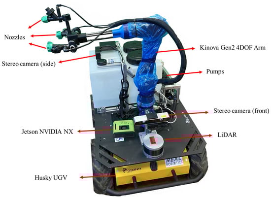
Figure 1.
The disinfection robotic system prototype.
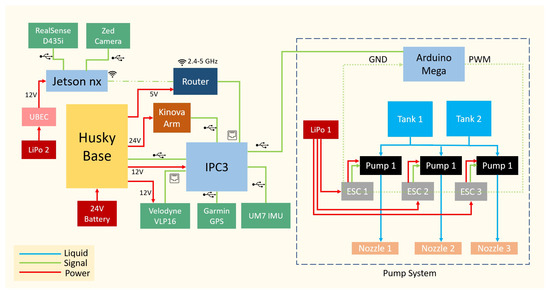
Figure 2.
Disinfection robot hardware system.
- Navigation/manipulation subsystem: This subsystem integrates the Clearpath Husky UGV base, a Kinova Gen2 robotic arm, and a Velodyne VLP-16 3D LiDAR (360° horizontal FOV, 100 m range, 10 Hz scan rate) for mapping and localization. Positioning is supported by a Garmin 18x LVC GPS receiver (2 m nominal accuracy) and a UM7 inertial measurement unit (3-axis accelerometer, gyroscope, and magnetometer). A 24 V battery and power management circuit supply the main propulsion and actuation modules. An industrial onboard computer (IPC3) running Linux coordinates navigation and control tasks.
- Computer vision subsystem: This subsystem includes an Intel RealSense D435i RGB-D camera and a ZED stereo camera, both connected to an NVIDIA Jetson Xavier NX module that handles image acquisition and real-time visual computation. A wireless router enables communication between the onboard units and the ground station.
- Spray subsystem: This subsystem consists of two 18 L chemical tanks and three diaphragm pumps, each coupled with an electronic speed controller (ESC) and a nozzle for spraying. An Arduino Mega microcontroller regulates the pump actuation through PWM control signals. The spray system is powered by a dedicated 12 V LiPo battery (LiPo 1) and communicates with the main computer through the IPC3 interface.
2.1.1. Spraying Module
Based on the guideline published by Centers for Disease Control and Prevention (CDC), one can consider the use of a solution containing at least 70% alcohol to disinfect frequently touched surfaces [21]. According to UKRI, the alcohol-based solution can inactivate SARS-CoV-2 virus particles by disrupting the structure of the proteins on the surface of the virus [22]. However, for this process to be effective, the alcohol solution needs to stay on the surface for several minutes to fully inactive the virus [10]. Based on the aforementioned studies, a spraying system capable of spraying 1.5 L/min of disinfection solution through three nozzles for maximum coverage is designed. The nozzles are connected to three pumps, which each has the maximum flow rate of 0.5 L/s. They can be controlled by a PWM signal received from a microcontroller, which is connected to the onboard main PC. The amount of disinfectant deposited on the target surface can be estimated using therelationship
where D is the deposition rate, Q is the effective flow rate of the pumps, v is the linear velocity of the mobile base and W is the effective spray footprint width at the chosen nozzle-to-surface distance.
Up to 36 L of disinfectant can be carried on the robot, allowing for long deployments. Two 18 L tanks were chosen rather than one larger tank as this reduces the liquid movement while the robot is in motion. They are made of medium density polyethylene (MDPE), which does not react to the disinfectant solution and one-way valves in the lids allows air to enter the system as the liquid is emptied. The tanks were raised above the pumps so that the pumps would be primed via gravity before being activated, and no air pockets would remain trapped in this part of the system. The two tanks are connected to the three pumps in parallel ensuring equal liquid distribution and resilience to a single component failure. Push fit pipe connectors were used to for rapid reliable connection of tubes.
Carbon fiber rods and 3D printed brackets were used to construct the spraying attachment. This created a lightweight, yet modular structure allowing for coverage adjustment if required. Polylactic acid (PLA) was used to prototype these parts however this can be changed to an inert polymer, such as polypropylene (PP) or nylon for longer term use. To further increase the coverage of the spraying system, for effective disinfection of large objects and easy adjustment, the nozzles are attached to a Kinova 4–DOF robotic arm. The robotic arm has the maximum reach of 75 cm and the payload of up to 3.5 kg, which easily supports the weight of the nozzles. Using the arm, the spraying robot can potentially cover the entire object in a single pass, considerably reducing the required time and material.
2.1.2. Sensory Modules
For smart operations in unknown environments sensing is a necessary component. To achieve autonomy in the disinfection robot, the robot is equipped with onboard stereo cameras and processing units, a LiDAR and an Inertial Measurement Unit (IMU) to provide sensory information for planning, navigation and spraying. The robot’s sensory system architecture is illustrated in Figure 3. The robot is equipped with two stereo cameras. The front camera is chosen to be a ZED stereo camera and there is also an Intel RealSense D435i attached to the side of the robot. Table 1 list the relevant specifications for both cameras.
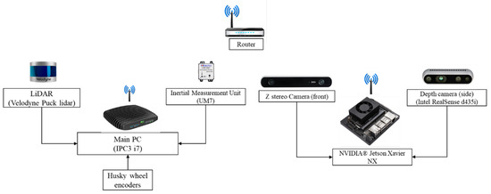
Figure 3.
Disinfection robot sensory system including the stereo cameras, LiDAR, GPS and IMU.

Table 1.
Key specifications of the cameras used in the disinfection robot.
ZED stereo camera (front camera) has a longer range of operation. This is an important advantage, which allows the robot to detect objects at a longer range and get the depth information more accurately guiding the robot to move towards the object. On the other hand, the side camera (Intel RealSense D435i) has a lower range of operation, which is enough for close-range operation during the spraying. It should be noted that the cameras are directly connected to a Jetson NX Xavier board (6-core NVIDIA Carmel ARM®v8.2 processor and 8 GB RAM) in charge of the image processing due to its powerful Graphics Processing Unit (GPU) given the compact build and low power consumption. The robot is also equipped with a 3D Velodyne LiDAR with the maximum 100 m operating range, which provides point cloud data to be used for navigation, mapping and obstacle avoidance. The LiDAR is placed in front of the robot and has at least 180 degree horizontal field of view without occlusion and it was decided not to be elevated to better detect low height obstacles.
2.2. Software System
The software architecture of the disinfection robot is built upon the Robot Operating System (ROS), which provides a modular and distributed framework suitable for managing multiple sensors and actuators. The ROS master (in charge of naming and registration) is hosted on the IPC3 onboard computer, which interfaces with the LiDAR, Husky motor drives, IMU and robotic arm. The stereo cameras are connected to an NVIDIA Jetson Xavier NX module, which handles image acquisition, object detection, and 3D pose estimation. A simplified overview of the software architecture, including the ROS nodes, messages and services, is illustrated in Figure 4.
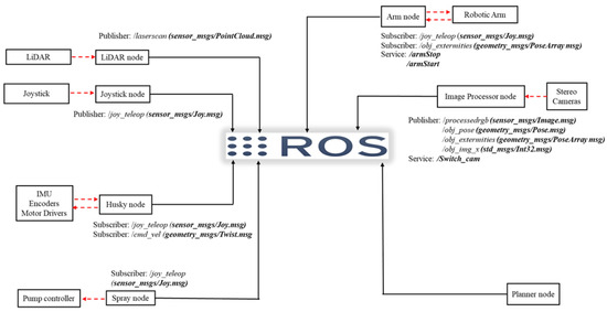
Figure 4.
Disinfection robot software system.
As shown in Figure 4, whether the node is connected to a physical device, such as the Joystick node or it only subscribes to published topics, such as the Planner node, it should be in constant communication with the ROS master. For example, the LiDAR node connected to the Velodyne LiDAR gets the information from the physical device and notifies the ROS master that it is ready to send data on the topic laserscan, of type PointCloud2 defined in the sensormsgs library. In the meantime, the Image Processor node also notifies the master that it wants to subscribe to that topic. Now that the topic has both a subscriber and a publisher the master notifies them, and they can communicate. This is also true for all the nodes registered with the ROS master, which enables them to easily share data.
The robot can operate in two modes: manual and autonomous. While operating in the manual mode the Bluetooth joystick publishes a message of type /Joy on /joyteleop topic, which is subscribed by the robotic arm, Husky and the pump controller. This allows the operator to fully control the robot in case manual operation is required. On the other hand, in the automatic mode, the robot only relies on the sensory information provided to the robot by the means of onboard sensing devices. The Image Processor node receives the RGB frames, point cloud and depth image directly from the cameras using the Stereolabs ZED SDK and Intel RealSense SDK 2.0 and detects the object of interest, obtain its location and orientation and send the result as a /PoseArray message to the planner node. The planner node uses the received information from the Image Processor node and the point cloud data from the LiDAR to generate a path for the robot and sends the commands to Husky and the robotic arm to be executed. The detailed operation of the Image processing node (Visual perception) and the Planner node (Motion planning) will be discussed in the next sections.
3. Visual Perception
Autonomous object detection is a critical capability for enabling the disinfection robot to operate effectively in unknown environments. To ensure precise spraying, it is not only necessary to identify objects of interest, but also to estimate their 3D position and orientation from onboard sensor data.
The object detection and segmentation tasks are handled by an NVIDIA Jetson Xavier NX module, which features a Volta GPU with 384 CUDA cores and 48 Tensor cores. The system processes RGB images captured by both the ZED stereo camera and the Intel RealSense D435i, using direct access through their respective SDKs rather than ROS nodes to reduce computational overhead. YOLOv4 [23] is employed to perform object detection, and its output, bounding boxes and class confidences, is published as a ROS message for subsequent planning and control. To infer the object’s pose required for motion planning, a point cloud segmentation algorithm is applied to the region defined by the bounding box.
3.1. Object Detection
Object detection, the task of identifying a specific object (matching) or a class of objects (labeling) within an image and determining their location, has long been a core challenge in computer vision [24]. This task is particularly difficult because objects within the same category (e.g., benches) can vary significantly in texture, color, and size. Moreover, environmental factors such as lighting conditions heavily influence detection accuracy. Combined with the sheer number of object classes and the requirement for large annotated datasets, object detection in images or video frames remains a non-trivial problem. The advent of Convolutional Neural Networks (CNNs) has dramatically transformed the field of object detection [25]. These advances, coupled with the availability of extensive labeled datasets such as MS COCO [26] and the high computational performance of modern GPUs [27], have enabled robust and scalable object detection systems.
Real-time object detection, crucial for autonomous robotic applications in unknown environments, has been made feasible through platforms such as You Only Look Once (YOLO) [23]. YOLO treats object detection as a regression problem and processes the entire image in a single pass, making it significantly faster than traditional sliding-window approaches. YOLOv4, for example, can efficiently localize objects in an image by outputting rectangular bounding boxes that tightly enclose each detected object [28]. Although retraining the CNN may be necessary for detecting specific object classes, the use of pre-trained models on datasets like MS COCO is often sufficient for common objects such as benches and chairs. This reduces the computational overhead associated with training large networks from scratch. Figure 5 illustrates the object detection results produced by YOLOv4, including bounding boxes and associated confidence scores.
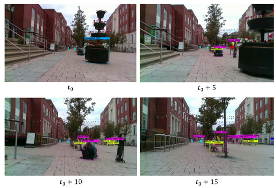
Figure 5.
Realtime object detection employing YOLOv4 trained on MS COCO data set using ZED camera (front camera).
Figure 5 presents four output frames captured during experiments in a public area. YOLOv4 successfully detected benches occupied by people and even those located at a greater distance. Despite occasional loss of detection due to lighting changes or vibrations, the algorithm demonstrated overall satisfactory performance. For each detection, YOLOv4 outputs a bounding box and assigns a confidence score indicating the likelihood of correctness. Key practical factors influencing real-time YOLOv4 performance include image frame size, GPU computational power, and the depth of the CNN model. When operating under limited computational resources, such as on the Jetson Xavier NX, one practical alternative is Tiny-YOLO, a lightweight version that sacrifices some accuracy for greater efficiency. A noteworthy practical observation was the instability caused by operating multiple Intel RealSense cameras on the same system. In experiments using two RealSense cameras, the data streams froze after a few minutes on the Jetson Xavier NX, due to SDK-related issues. In contrast, using a combination of ZED and RealSense cameras proved more stable, enabling prolonged operation without freezing.
Once an object is detected, the region enclosed by its bounding box is cropped and passed to the segmentation module for further processing. This step significantly reduces the computational burden compared to segmenting the entire point cloud. In the case of multiple detections, the object closest to the camera determined using depth information is selected. If depth information is unavailable due to occlusion or limited sensor range, the system defaults to the first detected object. Additionally, the horizontal offset between the center of the bounding box and the image center contains valuable spatial information. This offset is extracted and published as a ROS message, which can then be utilized for navigation and motion planning purposes.
3.2. Point Cloud Segmentation
For tasks requiring precise operations, such as targeted spraying, it is insufficient to merely infer the object’s location in a 2D image frame. Instead, the object’s full 3D pose, comprising both its position and orientation relative to the camera, must be estimated using sensor data. While the bounding box obtained from the YOLOv4 platform provides useful spatial constraints, the RGB image alone is only suitable for object detection and visualization. It cannot support accurate pose estimation, especially under the assumption that the object’s 3D model is unknown. Therefore, a dedicated point cloud segmentation algorithm is required to estimate the 3D pose.
The proposed segmentation pipeline is illustrated in Algorithm 1. The process begins by cropping the raw point cloud using the bounding box coordinates generated by YOLOv4. This focuses the computation on a smaller region of interest. A local search algorithm is then applied, initializing from the detected object center within a predefined spherical region. To eliminate outliers, the algorithm verifies that each point in the region has at least a minimum number of neighboring points within a specified radius. This segmentation process is implemented using a CUDA-based parallel algorithm, allowing simultaneous evaluation of multiple points and leveraging the massive parallelism of modern GPUs. On a 200 × 200 input image, the algorithm achieved an execution time of just 1 millisecond when running on an NVIDIA Quadro M2000M GPU, demonstrating its suitability for real-time applications.
| Algorithm 1 Pose Estimation Using Pointcloud Segmentation |
| Require: Point cloud , bounding box , pixel coordinate , search radius , noise threshold Ensure: Position , orientation
|
minimum points Ensure: Mask , filtered point cloud
|
Figure 6 illustrates a result produced by the segmentation algorithm. The camera used was the RealSense D435i and the chair was positioned 1.5 m away from the camera. Note that in this test, the camera was positioned at a height that made the chair’s backseat appear in the middle of the camera’s frame, similar to the side camera attached to the robot. Figure 6a shows that some of the points from the background is still picked up around the edges, however as seen in Figure 6b, the point cloud is unaffected by this. Figure 6b also shows a few outliers (points that are not connected to the chair) that have not been filtered out, this could be improved by imposing stricter conditions on the number of neighboring points and the distance between them, which will increase the computation burden.
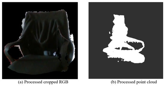
Figure 6.
Set of processed RGB and pointcloud.
The algorithm also generates a binary mask representing the object’s shape. This mask is used to extract the external contours of the object. From these contours, the extremities are identified and used to estimate the object’s orientation relative to the camera. Specifically, the yaw and pitch angles are derived from the horizontal and vertical extremities, respectively. The roll angle is estimated by computing the orientation of the minimum-area bounding rectangle around the contours. However, due to the way the neural network defines the bounding box, typically enclosing the entire object tightly and vertically, the resulting rectangle often aligns with the image axes. This causes the estimated roll to default to either 0 or 90 degrees, which may not be accurate. Nevertheless, this limitation is not critical, as the yaw angle is the most relevant for the disinfection robot’s operation. To calculate the yaw, the two horizontal extremities are used to construct a vector between them. The yaw angle is defined as the angle between this vector and the Y-Z plane of the camera’s coordinate frame. Let be the normal vector of the Y-Z plane. Then the angle can be calculated using the following equation:
Similarly, the pitch angle can be estimated using the vector formed by the vertical extremities, following the same approach but with respect to the X-Y plane, whose normal vector is . All vectors, planes, and angles are defined within the camera’s coordinate frame.
Figure 7a shows a processed RGB input, where the object’s edges are enclosed with a green border (region of interest) and the extremities are marked with white circles. The chair was 2 m away and the camera used was a RealSense D435i positioned at a 1.5 m height. The extremities were obtained such that they remain within a certain range of the object, this is to prevent cases in which the extremities would lie on the seat of the chair, which did not always provide valid depth values. The estimated error of the Yaw angle measurement is around 4 degrees, because of the existing noise in the Pointcloud data. Although this was an acceptable error range for the spraying robot, for more precise spraying, more accurate estimation might be required. The maximum processing speed in this case obtained to be around 15 FPS (Frames per Second) processing speed on the Nvidia Jetson Xavier NX.
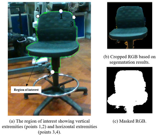
Figure 7.
Segmentation algorithm output.
The proposed method relies on a basic local search algorithm, which, due to its spherical search region and the assumption that only the target object is present within that region, may fail to fully capture the object’s extent or to reliably distinguish between adjacent objects. As a result, the segmentation may be incomplete or inaccurate in cluttered environments. To improve robustness and generalization, a more advanced clustering algorithm, such as DBSCAN [28], can be employed. DBSCAN is capable of identifying objects with arbitrary shapes and effectively separating nearby clusters, leading to more accurate segmentation. However, adopting this approach would require an additional post-processing step to distinguish and select the cluster corresponding to the object of interest. Compared to deep neural network–based pose estimation methods, such as PoseCNN [29], both the current method and the clustering-based alternative offer significant advantages in terms of efficiency and deployability. Specifically, they do not require training on large-scale 3D datasets and can be executed efficiently on embedded platforms equipped with CUDA-enabled GPUs.
It is also important to note that in low-light conditions or when viewing poorly textured objects, the ZED camera exhibited reduced depth accuracy, and in extreme cases failed to produce valid depth measurements. In contrast, the Intel RealSense camera demonstrated greater reliability under such conditions, primarily due to its built-in infrared (IR) emitter, which enhances depth sensing performance compared to the passive stereo approach used by the ZED camera.
4. Robot Navigation
The navigation module comprises two core submodules: motion planning (Section 4.1) and motion control (Section 4.2).
4.1. Motion Planning
Prior to initiating a disinfection mission, the environment must be digitally mapped and its unique features identified. The mapping process is performed by manually driving the robot or issuing low-velocity commands that guide it through the majority of the operational area. The quality of the resulting map is influenced by several factors, including the robot’s speed, the scanning frequency of the LiDAR sensors, and the presence of dynamic elements such as people or moving objects. Empirically, a body-frame velocity of approximately 0.1–0.2 m/s, combined with minimal movement around the robot and multiple mapping passes, was found to produce high-quality maps. These maps serve as a reliable reference for robot localization and navigation, significantly reducing the impact of odometry drift during long-duration tasks. To generate the map, the slamgmapping ROS node from the gmapping package is employed. Gmapping uses the laser scans from the lidar sensor in addition to the transforms relating the robotbase, odometry, laser, …, etc. The transform between the robot baselink and lidar sensor can be published as part of the robot transform or as a static transform. The transform between the map and odometry frame is automatically generated. The mapping node publishes the map data, including parameters like resolution and dimension, and the map that is presented by an occupancy grid. After generating the map, we execute two phases of map processing to enable our path planning: 1. Targets annotation and scoring and 2. Connected free spaces around each target. An illustration is provided in Figure 8.
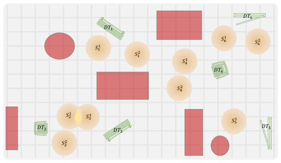
Figure 8.
Illustration of annotated map.
Obstacles within the grid are classified as either disinfection targets or general environmental obstacles, denoted as and respectively, and are represented using sparse two-dimensional arrays.Each obstacle is assigned a cost value reflecting its potential hazard, allowing the path planner to generate routes that maximize the distance from sensitive objects or areas with high likelihood of human movements. For each disinfection target , a set of connected free spaces is defined. These are navigable regions from which an obstacle-free path exists to the corresponding target. For simplicity in 2D representation, each space is modeled as a circular area with radius , where and are selected based on the robot’s physical dimensions and the detection range limitations of the perception system. To avoid ambiguity during path planning, connected spaces associated with the same target are constrained to be non-overlapping. However, free spaces corresponding to different targets are allowed to overlap, which may improve planning flexibility. A score is associated to every space based on the target orientation with respect to that location, type of the target, distance from other connected and unconnected spaces time required to disinfect the target, and the number of targets with obstacle free trajectories from that location. For example, spaces shared by multiple targets are associated with higher utility. In contrast, targets requiring longer time to disinfect reduce the score of the space.
The path planning task can be formulated as a constrained optimal coverage problem. In the case of two disinfection targets, the total operation time can be expressed as:
depending on which target is visited first. Here, denotes the travel time between locations i and j, and represents the average time required to disinfect target i. The disinfection time is assumed to be constant for a given type of target, and thus an average value is used in planning. When handling multiple targets n, the objective becomes minimizing the total mission time required to disinfect all targets. This is influenced by both target locations and the utility scores associated with candidate positions on the map. The problem can be approached using dynamic programming techniques. For a static environment with a fixed floor plan and stationary targets, an optimal policy can be computed as a baseline. This policy can then be dynamically updated during execution if the robot’s planned path is obstructed by moving obstacles in the operational area. The motion planner communicates the selected next target and the corresponding goal region (a connected free space near the target) in the map frame. The control module then receives this information and handles the local navigation and disinfection execution accordingly.
4.2. Robot Control
This section presents the control strategy that enables the robot to autonomously navigate from an arbitrary initial position on the map to the next disinfection target, as determined by the planning module. The control node operates based on real-time feedback from the state estimator, vision system, and LiDAR sensor. The control node is designed to fulfil four key objectives: avoiding obstacles in the environment, driving the robot to free space adjacent to the target, executing a target search manoeuvre, and performing a final approach toward the disinfection target. A representative navigation scenario involving a single target is illustrated in Figure 9.
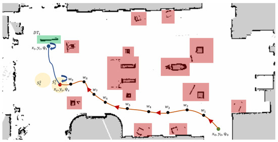
Figure 9.
Single target navigation example.
The robot begins at an initial pose , where represents its position and is its orientation. The center of the free-space region near the target is denoted by , while the target’s pose is represented by . Although the annotated map and the approximate target location are known in advance, the precise relative position of the target with respect to the robot is subject to uncertainty. Consequently, while the robot is globally controlled within the map frame, it also relies on onboard sensing particularly visual feedback for local motion planning and target refinement. To drive the robot from to , a constrained, obstacle-free trajectory is generated, defined by a sequence of waypoints that ensure both safety and smoothness. A customized version of the ROS movebase package is developed, which integrates pre-generated map data with onboard sensor inputs for both global and local planning. Each location on the map is treated as a global goal, and local motion control toward these goals is governed by odometry feedback from the localization module. Coordinate transformations between the map, odometry and base-link frames are essential for converting planned trajectories into meaningful velocity control commands. For simplicity, the low-level control commands consist of forward linear velocity in the robot’s body frame and yaw rate. The robot typically maintains a baseline constant velocity, which may be reduced near obstacles or in narrow passages where only direction adjustments are permitted. For safety, the system can override planner outputs by reducing speed or stopping entirely if a fast-moving obstacle is detected. The trajectory is defined by a sequence of waypoints connecting the initial pose to the region around the target. Each waypoint represents an intermediate position in the global map, selected to ensure obstacle avoidance and smooth navigation along the planned path. These waypoints are dispatched to the global planner using the ROS action library. The Husky platform receives body-frame velocity commands to initiate motion. During execution, odometry feedback is used to determine waypoint completion: a waypoint is considered reached when the robot’s current position satisfies the proximity condition
where denotes the Euclidean norm. is a predefined threshold and generally is set to 0.15 m, which provided a good balance between navigation precision and motion stability. Once this condition is met, the control loop halts and the next waypoint is issued.
When the robot reach , the first phase of the approach is completed, and the robot is now is in the neighbourhood of the disinfection target. From this position, it is assumed that the target can be detected using visual feedback from the onboard stereo camera system. In this phase, the final orientation at is not constrained, as the robot performs a scanning routine to locate the precise target position. This is achieved by applying an open-loop rotational velocity command to the mobile base (Husky). The robot rotates in place until the stereo vision system detects the target. Once the target is identified, the control switches to a closed-loop scheme, using the centroid of the detected object in the image frame to align the robot’s heading toward the target. The robot then proceeds toward the target at a constant forward velocity. Upon detecting valid depth data for the object at pose , a local PID controller is engaged to precisely guide the robot from to the final disinfection position . This control loop relies on continuous visual feedback, including the object’s center and estimated orientation. Once the robot reaches the vicinity of the object, it aligns itself at the center of the object and begins the disinfection process. If the target object is spatially large relative to the effective coverage width of the disinfection spray, the robot moves along the length of the object to ensure full coverage. During this operation, the manipulator control node is activated to initiate spraying while the robot moves along the target. Upon completion of the disinfection task confirmed via feedback from both the vision system and the manipulator controller, the navigation module receives a completion signal. Control authority is then handed back to the planner module, which proceeds to issue the next disinfection target.
5. Experimental Results
This section presents real-world experimental tests of the disinfection robotic system in indoor and outdoor public spaces. The robot autonomously disinfected various frequently touched objects, with particular emphasis on sitting benches as representative targets due to their common presence and frequent human interaction. The robot did not rely on pre-stored target coordinates. All disinfection targets were detected online through visual perception, and navigation and spraying were executed accordingly.
5.1. Indoor Disinfection Operation
Indoor experiments were conducted in the foyer of the School of Mechanical Engineering at the University of Leeds. The environment includes various structural and functional elements such as a service counter, multiple doors, stairways, chairs, and tables, providing a representative semi-structured indoor setting. A sitting bench with dimensions m was randomly repositioned across different trials to introduce variability and assess the system’s adaptability. The objective of this test is to comprehensively validate the system’s autonomous capabilities, encompassing pre-processing of the environment map, path planning, vehicle control, dynamic obstacle avoidance, and vision-based perception for environment understanding and task execution.
A 2D map of the environment, as shown in Figure 9, was generated using the gmapping package in ROS, which integrates LiDAR scan data with odometry and pose estimation [30]. Configuration details and parameter tuning guidelines for the package can be found in [31]. Starting from an initial pose, the robot was driven around the area at a constant speed of 0.1 m/s. The resulting map, saved using the ROS map server, was subsequently processed offline for semantic annotation and task planning. For experimental evaluation, three categories of convex regions of interest were defined: obstacles, targets (a single target in this experiment), and free areas surrounding the targets. Each obstacle was enclosed within a rectangular bounding box defined by four corner points: . The pose of the target object was modeled as a set of random variables with Gaussian distributions, capturing the uncertainty in position and orientation due to sensor noise and localization inaccuracies. The mean and variance parameters were estimated from the corresponding sensor data streams. In the implementation, the mean values of all sensor noise distributions were assumed to be zero, while the variance parameters were empirically estimated from stationary data samples collected prior to each experiment. Specifically, the IMU angular velocity and linear acceleration variances were approximately and , respectively, whereas the GPS positional variance was about 0.25 m2. These values were used as the noise parameters in the sensor fusion module. The target was treated as a special type of obstacle with attractive rather than repulsive properties, and was also defined using four corner points forming a bounding box. To account for uncertainty in the target’s orientation, it was assumed that the angular deviation could vary within a range around the expected yaw angle , i.e., . This uncertainty was addressed locally by a vision-based orientation estimation module. The free areas around the target were defined as circular zones with a diameter of 1.5 m. In the specific scenario under consideration, two candidate non-overlapping free regions, denoted as and , were identified to support task planning (see Figure 9).
In the initial phase of navigation, robot motion is planned within a global inertial frame using a pre-constructed static map. Based on the robot’s initial pose, the planner node selects a target location, denoted as . Robot localization relative to the map is performed using the adaptive Monte Carlo localization (AMCL) algorithm, as implemented in ROS [32,33]. AMCL integrates the known static map, real-time lidar scans, the robot’s transform tree, and its initial pose to estimate the current position. In this experiment, the initial pose is assumed to be known and is directly provided to the AMCL node as the initial state of the particle filter. The resulting pose estimate is utilized for both local and global motion planning. The ROS movebase package serves as an interface between the navigation goal and the robot’s low-level control system, generating velocity commands to drive the mobile platform [34]. Two control inputs are computed: the translational velocity along the robot’s x-axis in the body frame and the angular velocity about the vertical axis . These control inputs are depicted in Figure 10a and Figure 10c, respectively. In this experiment, the forward velocity is held constant unless a nearby obstacle necessitates deceleration. The robot’s motion from the initial location to a region adjacent to the disinfection target is primarily governed by adjusting its heading through angular velocity control. This process corresponds to the time interval in Figure 10.
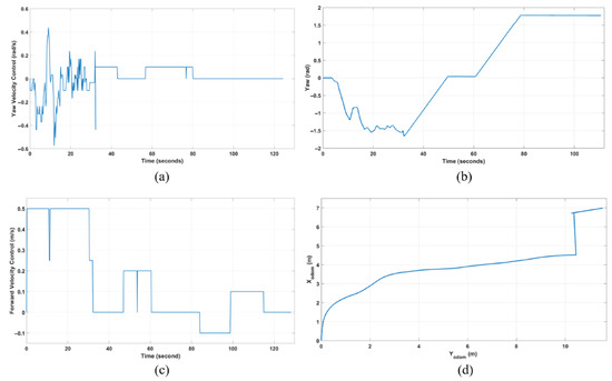
Figure 10.
Indoor experiment control inputs and outputs of the UGV, (a,b) shows the control inputs, (c) yaw output, and (d) robot path.
Once the robot reach area near the target object, the second navigation phase to search for the target starts. In this phase, the robot performs in-place rotation until the target is detected using RGB vision feedback. Once the target is identified and the robot is approximately centered with respect to it, the third phase begins: target approach. As the robot advances toward the target (Figure 11b,e), the reliability of both the depth data and the segmented point cloud (Figure 11a) improves. Empirical trials indicate that the vision-based depth and segmentation data become consistently reliable when the robot is within approximately 3 m of the object. The estimated relative position and orientation of the target bench, obtained via point cloud segmentation as described in Section 3, are illustrated in Figure 12. The 2D position of the target is then used for local path planning and velocity control to guide the robot to its operational position. The parking phase is started when the robot is at some distance from the target, which is determined based on the physical size of the object and the reachability of the onboard manipulator. In this experiment, the parking phase begins at a 1-m distance from the target. The robotic manipulator, equipped with a spray nozzle, is configured to operate laterally, aligned with the robot’s body-frame -axis. At this stage, the vision input is switched to the side-mounted depth camera, enabling the robot to rotate in place and align itself with the target’s orientation. The orientation is estimated from the processed side-camera data and used to refine the robot’s alignment (Figure 10). A maximum allowable relative orientation error of 0.05 radians is set in this experiment to ensure precise alignment. The estimated relative pose and extremities of the target object (Figure 12) are continuously updated as the robot approaches. The vertical extremities are employed to define the motion range of the end-effector, ensuring complete coverage of the target surface. The horizontal extremities serve as independent spatial references for determining the start and end positions of the ground robot and spray system during the disinfection process.
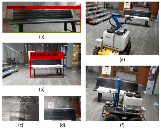
Figure 11.
Vision based approach and target disinfection, (a) detected object boundaries and extremities from segmented point cloud. (b) Object detection and classification using YOLO. (c) Comparison between exposed and covered portion of the bench after operating. (d) Robot camera view during target spray. (e) Final approach toward the target. (f) Robot disinfecting the target.
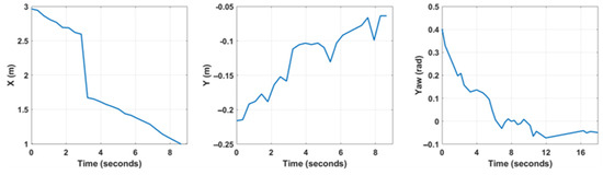
Figure 12.
Estimated target pose during final approach and alignment.
Once the robot is aligned with the target object, it advances toward one edge of the object. Prior to initiating the disinfection process, both the robotic manipulator and the disinfectant pump system are initialized. The UGV then moves at a constant speed toward the opposite edge of the object, as illustrated in Figure 11f. Although the pump system is capable of operating at variable speeds, a constant spray rate is used in this experiment. This is because the target object exhibits a uniform shape, and the UGV maintains a consistent distance from its surface throughout the operation. During the disinfection process, the robotic manipulator extends toward the bench, and the spray nozzle executes a sinusoidal motion along the vertical axis to ensure full surface coverage. This motion is achieved by coordinating two joints of the robotic arm. The positions of the manipulator joints and the end-effector during the spraying operation are depicted in Figure 13. Upon reaching the far edge of the object, the pump system is deactivated and the robotic manipulator retracts to its standby position. At this point, the disinfection task is considered complete, and the robot is ready to proceed to the next designated target. Surface coverage results are presented in Figure 11c, which highlights the areas of the bench that have been sprayed versus those left uncovered. It is worth noting that in this experiment, the back side of the bench was excluded from the disinfection plan, based on the assumption that it is rarely touched in public environments.
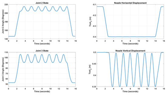
Figure 13.
Manipulator joint states and end-effector position.
5.2. Outdoor Disinfection Operation
The outdoor disinfection experiment was conducted in a public green park, where three target benches were selected for testing. Prior to deployment, the operational area of the park was mapped, and the approximate locations of the three disinfection targets, denoted as , were recorded, as illustrated in Figure 14. The robot initiates the operation from an arbitrary pose . Based on this initial state, the path planner generates a sequence of target poses within the global map frame. Each target pose is associated with a corresponding circular region . The selection of these regions considers three main criteria: (1) the grid-based distance from the robot’s initial pose, (2) the existence of at least one obstacle-free path from the region to the target, and (3) sufficient proximity to enable reliable vision-based target detection. The three benches vary in both size and shape. Figure 14 shows the detection results with high confidence. The estimated boundaries of the targets are highlighted in green contours, while their centers and extremities are marked with red and blue dots, respectively. Although the estimated center and extremities are influenced by the robot’s relative orientation to the target, the errors remain within acceptable limits, which can be compensated for by the robot’s final alignment procedure and the spray system’s effective coverage. During the disinfection process, the left and right extremities of the bench are used to trigger the start and stop of the spraying operation. Meanwhile, the top and center points are employed to determine the vertical range of motion for the robotic manipulator’s end-effector, ensuring full vertical coverage of the bench surface.
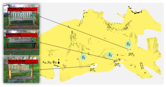
Figure 14.
Outdoor map for the disinfection mission covering three targets and objects detection.
Unlike the indoor trial, both control inputs are allowed to vary throughout the outdoor operation, subject to an upper limit on the forward velocity, as illustrated in Figure 15a,b. These control inputs are generated by a PID controller, which guides the robot during navigation and disinfection tasks. The navigation process is structured into tasks and sub-tasks. Tasks correspond to the sequence of targets determined by the high-level planning module, while sub-tasks define the five operational phases required to approach and disinfect each individual target. For the mission example shown in Figure 14, given the specified starting pose and target locations, the planner generates the sequence , based on obstacle-free areas and relative proximity to the initial robot position. The local planner then executes the following five-phase procedure for each target:
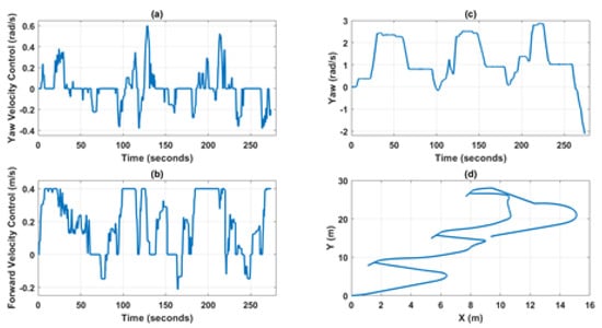
Figure 15.
Outdoor experiment control inputs and outputs of the UGV, (a,b) shows the control inputs (c) yaw output, and (d) robot path.
First, The robot moves from its current pose to the designated area associated with . Upon arrival at , the robot searches for and aligns itself with the detected target. Then, the robot advances toward the target center until it reaches the predefined operational distance. A fine-tuned parking routine is executed to correct any residual orientation error. Finally, the robot performs the spraying operation along the longitudinal axis of the object.
Upon completion of disinfection for a given target, the robot’s current pose is used as the starting point for navigating to the next designated area (e.g., ), and the process is repeated. After completing all tasks, the robot either returns to its initial starting position or proceeds to a predefined final location. The cyclic structure of this operation is evident in the robot’s trajectory, as depicted in Figure 15d. In this experiment, the robot operates within a bounded area of approximately m, and the complete disinfection mission is accomplished in approximately 4.5 min. The overall operation time is significantly affected by safety constraints on velocity, particularly when maneuvering near targets to ensure safe and accurate disinfection.
6. Conclusions
This paper presented the development and evaluation of an autonomous robotic system for disinfection operations in indoor and outdoor public environments. The robot is capable of autonomously locating frequently touched objects and performing surface disinfection. Both the mobile manipulation platform and the configuration of the sensing modules were customized to meet the specific requirements of the disinfection task. The system integrates an in-house-designed pump-spray module tailored for autonomous spraying applications. A vision-based target detection and classification pipeline was introduced, with particular emphasis on the use of point cloud segmentation. The effectiveness and limitations of this approach were analyzed in various environmental conditions. Experimental results from laboratory settings and real-world field trials demonstrate that the proposed method can operate efficiently on a compact onboard computing platform. The software framework, implemented primarily using the Robot Operating System (ROS), incorporates both standard and custom-developed packages for perception, planning, and control. A comprehensive framework for executing disinfection operations in real-world scenarios was proposed and successfully implemented on the developed robotic system. The experimental results validate the effectiveness of the proposed solution in performing reliable and repeatable surface spraying tasks.
Future work would proceed along two main directions: (1) the development of a custom-designed mobile robotic platform with enhanced kinematic capabilities to address reachability issues and enable more precise manipulation near target surfaces and (2) the integration of advanced sensing and planning strategies. In particular, encoding 3D models of common targets will be investigated to improve detection robustness under varying environmental conditions. Moreover, future research will focus on improving the adaptability and responsiveness of the motion planning system. By incorporating real-time re-planning across different phases of the operation, the system can better handle environmental disturbances and uncertainties, thereby reducing mission completion time and minimizing potential disruptions caused by the robot’s actions.
Author Contributions
Conceptualization, M.Z.S., L.H., B.K. and R.C.R.; methodology, M.Z.S., L.H. and M.J.K.; software, M.Z.S., M.J.K. and W.H.; validation, M.Z.S., W.H., M.M., P.M., N.F. and T.W.; formal analysis, M.Z.S. and L.H.; investigation, M.Z.S., M.J.K., W.H., M.M. and P.M.; resources, T.W., B.K. and R.C.R.; data curation, M.Z.S. and M.M.; writing—original draft preparation, M.Z.S. and L.H.; writing—review and editing, L.H., B.K. and R.C.R.; visualization, M.Z.S., M.J.K. and W.H.; supervision, B.K. and R.C.R.; project administration, R.C.R.; funding acquisition, R.C.R. All authors have read and agreed to the published version of the manuscript.
Funding
This work was supported by the Engineering and Physical Sciences Research Council (EPSRC), [Grant No. EP/N010523/1].
Data Availability Statement
The original contributions presented in the study are included in the article. Further inquiries can be directed to the corresponding author.
Conflicts of Interest
The authors declare no conflicts of interest.
References
- Hopkins, J. COVID-19 Map. 2022. Available online: https://coronavirus.jhu.edu/map.html (accessed on 25 November 2025).
- WHO. Transmission of SARS-CoV-2: Implications for Infection Prevention Precautions. 2020. Available online: https://www.who.int/news-room/commentaries/detail/transmission-of-sars-cov-2-implications-for-infection-prevention-precautions (accessed on 25 November 2025).
- Yang, G.Z.; Nelson, B.J.; Murphy, R.R.; Choset, H.; Christensen, H.; Collins, S.H.; Dario, P.; Goldberg, K.; Ikuta, K.; Jacobstein, N.; et al. Combating COVID-19—The role of robotics in managing public health and infectious diseases. Sci. Robot. 2020, 5, eabb5589. [Google Scholar] [CrossRef] [PubMed]
- Begić, A. Application of service robots for disinfection in medical institutions. In Proceedings of the International Symposium on Innovative and Interdisciplinary Applications of Advanced Technologies; Springer: Cham, Switzerland, 2017; pp. 1056–1065. [Google Scholar]
- Kovach, C.R.; Taneli, Y.; Neiman, T.; Dyer, E.M.; Arzaga, A.J.A.; Kelber, S.T. Evaluation of an ultraviolet room disinfection protocol to decrease nursing home microbial burden, infection and hospitalization rates. BMC Infect. Dis. 2017, 17, 186. [Google Scholar] [CrossRef] [PubMed]
- Jones, J.L.; Mack, N.E.; Nugent, D.M.; Sandin, P.E. Autonomous Floor-Cleaning Robot. U.S. Patent 6,883,201, 26 April 2005. [Google Scholar]
- Hu, D.; Zhong, H.; Li, S.; Tan, J.; He, Q. Segmenting areas of potential contamination for adaptive robotic disinfection in built environments. Build. Environ. 2020, 184, 107226. [Google Scholar] [CrossRef] [PubMed]
- WHO. COVID-19 Mythbusters. 2020. Available online: https://www.who.int/emergencies/diseases/novel-coronavirus-2019/advice-for-public/myth-busters#virus (accessed on 25 November 2025).
- Mackenzie, D. Ultraviolet light fights new virus. Engineering 2020, 6, 851. [Google Scholar] [CrossRef] [PubMed]
- Moorer, W. Antiviral activity of alcohol for surface disinfection. Int. J. Dent. Hyg. 2003, 1, 138–142. [Google Scholar] [CrossRef] [PubMed]
- Kalantari, D.; Shayanmehr, M.; Refigh, A. Evaluation of the spray generated by a greenhouse spraying robot. Agric. Eng. Int. CIGR J. 2014, 16, 55–60. [Google Scholar]
- Wang, P.; Wang, P.; Geng, C. A combined visual navigation method for greenhouse spray robot. In Proceedings of the 2019 IEEE 9th Annual International Conference on CYBER Technology in Automation, Control, and Intelligent Systems (CYBER), Suzhou, China, 29 July–2 August 2019; pp. 604–608. [Google Scholar]
- Sharma, S.; Borse, R. Automatic agriculture spraying robot with smart decision making. In Proceedings of the International Symposium on Intelligent Systems Technologies and Applications, Sinaia, Romania, 2–5 August 2016; Springer: Cham, Switzerland, 2016; pp. 743–758. [Google Scholar]
- Wang, Z.; Jing, F.; Fan, J.; Liu, Z.; Tian, Y.; Gao, Z. Object Pose Estimation Based on RGB-D Sensor for Cooperative Spray Painting Robot. In Proceedings of the 2019 IEEE 9th Annual International Conference on CYBER Technology in Automation, Control, and Intelligent Systems (CYBER), Suzhou, China, 29 July–2 August 2019; pp. 311–316. [Google Scholar]
- Xia, C.; Li, Y.; Chon, T.S.; Lee, J.M. A stereo vision based method for autonomous spray of pesticides to plant leaves. In Proceedings of the 2009 IEEE International Symposium on Industrial Electronics, Seoul, Republic of Korea, 5–8 July 2009; pp. 909–914. [Google Scholar]
- Feng, Q.C.; Wang, X. Design of disinfection robot for livestock breeding. Procedia Comput. Sci. 2020, 166, 310–314. [Google Scholar] [CrossRef]
- Cepolina, F.E.; Muscolo, G.G. Design of a robot for hygienization of walls in hospital environments. In Proceedings of the ISR/Robotik 2014; 41st International Symposium on Robotics, Munich, Germany, 2–3 June 2014; pp. 1–7. [Google Scholar]
- Ramalingam, B.; Yin, J.; Rajesh Elara, M.; Tamilselvam, Y.K.; Mohan Rayguru, M.; Muthugala, M.; Félix Gómez, B. A human support robot for the cleaning and maintenance of door handles using a deep-learning framework. Sensors 2020, 20, 3543. [Google Scholar] [CrossRef] [PubMed]
- Clearpath. Husky-unmanned ground vehicle. In Technical Specifications; Clearpath Robotics: Kitcener, ON, Canada, 2013. [Google Scholar]
- Kinova. Kinova Gen2. 2018. Available online: https://www.kinovarobotics.com/product/gen2-robots (accessed on 25 November 2025).
- CDC. Cleaning and Disinfection for Households. 2020. Available online: https://stacks.cdc.gov/view/cdc/88412/cdc_88412_DS1.pdf (accessed on 25 November 2025).
- UKRI. Disinfecting Surfaces for Coronavirus: Does It Reduce Infection? 2020. Available online: https://coronavirusexplained.ukri.org/en/article/pub0006/ (accessed on 25 November 2025).
- Redmon, J.; Divvala, S.; Girshick, R.; Farhadi, A. You only look once: Unified, real-time object detection. In Proceedings of the IEEE Conference on Computer Vision and Pattern Recognition, Las Vegas, NV, USA, 27–30 June 2016; pp. 779–788. [Google Scholar]
- Liu, L.; Ouyang, W.; Wang, X.; Fieguth, P.; Chen, J.; Liu, X.; Pietikäinen, M. Deep learning for generic object detection: A survey. Int. J. Comput. Vis. 2020, 128, 261–318. [Google Scholar] [CrossRef]
- Krizhevsky, A.; Sutskever, I.; Hinton, G.E. Imagenet classification with deep convolutional neural networks. In Proceedings of the Advances in Neural Information Processing Systems 25 (NIPS 2012), Lake Tahoe, NV, USA, 3–6 December 2012; Volume 25, pp. 1097–1105. [Google Scholar]
- Lin, T.Y.; Maire, M.; Belongie, S.; Hays, J.; Perona, P.; Ramanan, D.; Dollár, P.; Zitnick, C.L. Microsoft coco: Common objects in context. In Proceedings of the European Conference on Computer Vision, Zurich, Switzerland, 6–12 September 2014; Springer: Cham, Switzerland, 2014; pp. 740–755. [Google Scholar]
- Kirk, D. NVIDIA CUDA software and GPU parallel computing architecture. In Proceedings of the 6th International Symposium on Memory Management, Montreal, QC, Canada, 21–22 October 2008. [Google Scholar]
- Birant, D.; Kut, A. ST-DBSCAN: An algorithm for clustering spatial–temporal data. Data Knowl. Eng. 2007, 60, 208–221. [Google Scholar] [CrossRef]
- Xiang, Y.; Schmidt, T.; Narayanan, V.; Fox, D. Posecnn: A convolutional neural network for 6d object pose estimation in cluttered scenes. arXiv 2017, arXiv:1711.00199. [Google Scholar]
- Grisetti, G.; Stachniss, C.; Burgard, W. Improved techniques for grid mapping with rao-blackwellized particle filters. IEEE Trans. Robot. 2007, 23, 34–46. [Google Scholar] [CrossRef]
- Abdelrasoul, Y.; Saman, A.B.S.H.; Sebastian, P. A quantitative study of tuning ROS gmapping parameters and their effect on performing indoor 2D SLAM. In Proceedings of the 2016 2nd IEEE International Symposium on Robotics and Manufacturing Automation (ROMA), Ipoh, Malaysia, 25–27 September 2016; pp. 1–6. [Google Scholar]
- Fox, D.; Burgard, W.; Dellaert, F.; Thrun, S. Monte carlo localization: Efficient position estimation for mobile robots. In Proceedings of the Sixteenth National Conference on Artificial Intelligence and Eleventh Conference on Innovative Applications of Artificial Intelligence, Orlando, FL, USA, 18–22 July 1999. [Google Scholar]
- Pfaff, P.; Burgard, W.; Fox, D. Robust monte-carlo localization using adaptive likelihood models. In Proceedings of the European Robotics Symposium 2006, Palermo, Italy, 16–18 March 2006; Springer: Berlin/Heidelberg, Germany, 2006; pp. 181–194. [Google Scholar]
- ROS. move_base Package, ROS Navigation. 2016. Available online: http://wiki.ros.org/move_base (accessed on 25 November 2025).


Disclaimer/Publisher’s Note: The statements, opinions and data contained in all publications are solely those of the individual author(s) and contributor(s) and not of MDPI and/or the editor(s). MDPI and/or the editor(s) disclaim responsibility for any injury to people or property resulting from any ideas, methods, instructions or products referred to in the content. |
© 2025 by the authors. Licensee MDPI, Basel, Switzerland. This article is an open access article distributed under the terms and conditions of the Creative Commons Attribution (CC BY) license (https://creativecommons.org/licenses/by/4.0/).