Review

An Overview of Contrasting Experimental Results on Dynamics of Kinesin-1 Molecular Motors: Insight into the Underlying Mechanism

Laboratory of Soft Matter Physics, Institute of Physics, Chinese Academy of Sciences, Beijing 100190, China
Biomolecules 2025, 15(10), 1453; https://doi.org/10.3390/biom15101453
Submission received: 8 September 2025 / Revised: 3 October 2025 / Accepted: 11 October 2025 / Published: 14 October 2025

Abstract

The conventional kinesin (kinesin-1) molecular motor is a prototypical member of the kinesin superfamily. It can processively step on microtubules toward the plus end by hydrolyzing ATP molecules, performing the biological function of shuttling cargos in cells. Its dynamics have been thoroughly studied using various methods including biochemical measurement, single molecule imaging, single molecule optical trapping, and so on. While most of the experiments yielded consistent results on the dynamics of the motor, a lot of conflicting experimental results have also been presented. Here, a brief review is given of the diverse conflicting experimental results. Furthermore, a model for the chemomechanical coupling of the motor is briefly reviewed, which can consistently and quantitatively explain these conflicting experimental results in addition to the other experimental results. A consistent explanation of the diverse conflicting experimental results with the same model is an essential criterion for determining the correctness of the model.

1. Introduction

Kinesin proteins constitute a large superfamily of molecular motors, which can be categorized into 14 families and an uncategorized family called the ‘orphan kinesin’ [1,2,3,4,5]. Kinesin-1 was the first-found member of the superfamily [6,7] and has been thoroughly studied [8,9,10,11,12]. In this review, unless otherwise pointed out, we concentrate on the wild type (WT) kinesin-1 motor, which is simply called the ‘kinesin motor.’ The kinesin motor has a homodimeric form consisting of a pair of identical motor domains (also called ‘heads’) that are linked together by a long coiled-coil stalk through their two flexible neck linkers (NLs), with each NL having 14 amino acids [13]. After landing on microtubule (MT), powered by ATP binding and hydrolysis, the kinesin motor can step along MT toward the plus end with a velocity of about 800 nm/s for a long distance of about 1 μm before dissociation [14,15], performing the biological function of shuttling cargos in cells [1,2,3,4,5]. An interesting and important issue for the kinesin motor is how the chemical energy arising from the ATP binding and hydrolysis is converted to the mechanical energy of the directional motion (i.e., the mechanism of chemomechanical coupling). To address the issue, in addition to structural studies [13,16,17,18,19,20,21], the dynamics of the motor have also been investigated in great detail by using various methods, including biochemical measurement [22,23,24,25], single molecule imaging [26,27,28,29], single molecule optical trapping [14,15,30,31,32,33,34,35,36,37,38,39], coarse-grained and atomistic molecular dynamics (AMD) simulation [40,41,42,43,44,45,46,47], theoretical modeling and analysis [48,49,50,51,52,53,54,55,56,57,58], etc.
It was definitively determined that the dimeric kinesin motor processively steps along an MT filament in a hand-over-hand way and rarely takes sideways steps [59,60]. It takes either forward steps or backward steps with the size of about 8 nm that is equal to the period of tubulins on an MT filament [28,29,30,39]. Under no load and a small backward (minus-end-directed) load, the motor mainly steps forward and occasionally steps backward [14,15,30,31,32,33,34,35,36,37,38,39]. As the backward load increases, the number of the forward steps decreases while that of the backward steps increases. Under a backward load of about 6–8 pN—the stall force—the motor steps forward and backward with the same probability, with no net movement [31,32,33,34,35,36,37,38]. Under a backward load larger than the stall force, the motor mainly steps backward [36,61,62]. Both the forward and backward steps require ATP binding and hydrolysis [30,34,36,61].
However, it is perplexing that a plethora of contrasting experimental results have been presented on the dynamics of the kinesin motor. Here, we present a brief review on the contrasting experimental results. Furthermore, we briefly review a model for the chemomechanical coupling of the kinesin, which can consistently explain these contrasting experimental results as well as other experimental results. A consistent explanation of the diverse contrasting experimental data using the same model is crucial to the mechanism of the chemomechanical coupling of the kinesin.

2. ATP Binding Occurs in One-Head-Bound or Two-Heads-Bound State

It is known that during the processive motion, the kinesin dimer alternates between one-head-bound (1HB, with one head bound to MT) and two-heads-bound (2HB, with both heads bound to MT) states [26,27,28,29,39,63,64,65]. The directional motion is powered by ATP binding and hydrolysis [30,34,36,61]. Thus, an interesting issue is whether ATP binding occurs in the 1HB or 2HB state. Three independent experiments have been performed to address the issue [26,27,28].
In one experiment, Isojima et al. [27] attached a gold particle (20 nm or 40 nm) to a cysteine amino acid (S55C) at the rear position of one head of the human kinesin dimer via two polypeptide chains. They imaged the particle using the total internal reflection dark-field microscopy to measure the lifetimes of the 1HB and 2HB states of the dimer in a stepping cycle versus ATP concentration. They found that as the ATP concentration decreases, the lifetime of the 1HB state increases largely, whereas that of the 2HB state remains unchanged (Figure 1a). This indicates that ATP binding occurs in the 1HB state.
In another experiment, Mickolajczyk et al. [26] attached a 30 nm gold particle to the center right of one head of the Drosophila kinesin dimer via a short linker of the contour length of only 2.91 nm. They imaged the particle using the interferometric scattering microscopy to measure the lifetimes of the 1HB and 2HB states of the dimer in a stepping cycle versus ATP concentration. They found that as the ATP concentration decreases, the lifetime of the 1HB state increases slightly, whereas that of the 2HB state increases largely (Figure 1b), which is contrary to that observed by Isojima et al. [27]. The experimental results measured by Mickolajczyk et al. [26] indicate that ATP binding occurs mainly in the 2HB state.
In the third experiment, Wolff et al. [28] labeled an approximately 1 nm–sized fluorophore to a solvent-exposed cysteine located at the C-terminal end of the α6 helix on one head. They employed the interferometric MINFLUX microscope to measure the lifetimes of the 1HB and 2HB states of the dimer in a stepping cycle versus ATP concentration. They found that as the ATP concentration decreases, the lifetime of the 1HB state increases largely, whereas that of the 2HB state remains constant (Figure 1c), which is similar to that observed by Isojima et al. [27].
Taken together, the experimental results by Isojima et al. [27] and those by Wolff et al. [28] indicated that ATP binding occurs in the 1HB state. On the contrary, the experimental results by Mickolajczyk et al. [26] indicated that ATP binding occurs mainly in the 2HB state.

3. Velocity Versus Backward Load Has a Sigmoid or Linear Form

As the kinesin motor performs the biological function of shuttling cargo, it is constructive to determine the dependence of the motor’s velocity upon the load acting on the motor. The load dependence of the velocity was usually determined using the single molecule optical trapping techniques, where a large-sized bead is attached to the motor’s stalk. Two types of the trap have been utilized in the experiments. One type is termed as the ‘fixed trap,’ where the trap is kept stationary during the processive motion of the motor [15,68]. For the fixed trap, the load on the motor changes as the motor processively moves. The other type is termed as the ‘movable trap,’ which can be achieved by controlling the position of the trap utilizing acoustic optical deflectors during the processive motion of the motor to ensure a constant load on the motor as the motor processively moves [69]. Using both types of the trap, the dependence of the motor’s velocity on the load has been extensively studied [32,33,34,35,36,37,38,39,70,71,72,73]. In this section, we briefly review the contrasting experimental results about the velocity versus backward load. Throughout, the backward (forward) load is defined as having the positive (negative) value.
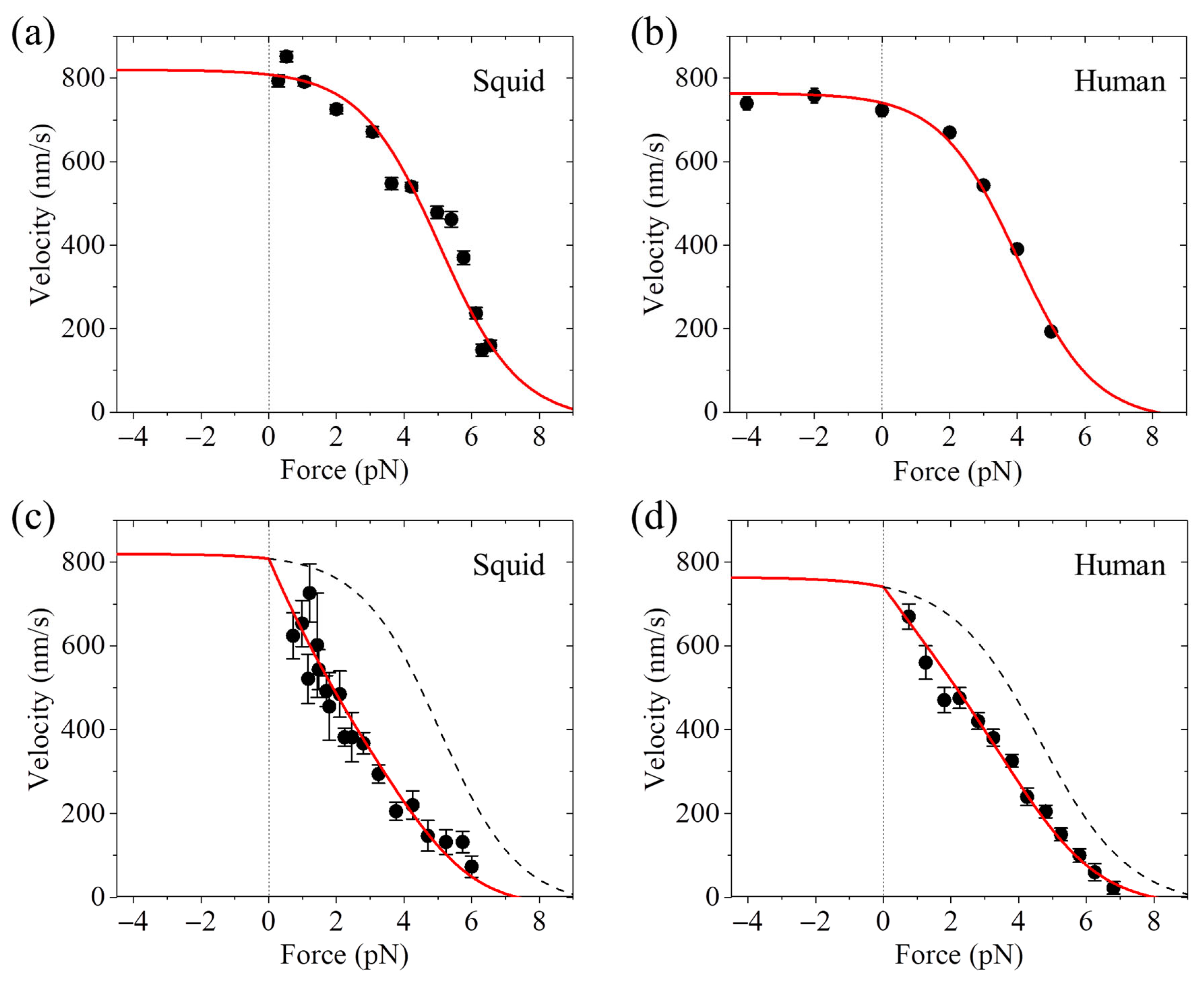
Using the movable trap, it was generally obtained that the motor’s velocity decreases slowly with the increase in the backward load when the load is small, decreases quickly when the load has the medium and large values, and decreases slowly again when the load is near the stall force [33,35,37,70]; namely, the relation between the velocity and backward load exhibits a sigmoid form (Figure 2a,b). In contrast, using the fixed trap, it was generally obtained that the velocity decreases almost linearly with the increase in the backward load when the load is smaller than the stall force [32,34,39,71,72,73]; namely, the relation between the velocity and backward load exhibits a nearly linear form (Figure 2c,d). In particular, the same research group of Block et al. [33,72] evidently showed that the same squid optic lobe kinesin has the sigmoid form of the velocity versus backward load determined using the movable trap (Figure 2a), whereas it has the nearly linear form determined using the fixed trap (Figure 2c). For the same human kinesin, using the movable trap, Andreasson et al. [37] determined the sigmoid form of the velocity versus the backward load (Figure 2b), whereas using the fixed trap, Kaseda et al. [71] determined the nearly linear form (Figure 2d).
In short, using the movable optical trap, it was determined that the relation between the velocity and backward load generally has a sigmoid form [33,35,37,70], as shown in Figure 2a,b. In contrast, using the fixed optical trap, it was determined that the relation between the velocity and backward load generally has a nearly linear form [32,34,39,71,72,73], as shown in Figure 2c,d.

4. Velocity Is Independent of or Decreases with or Increases with Forward Load

In this section, we briefly review the contrasting single molecule optical trapping results on the relation between the velocity and forward load.
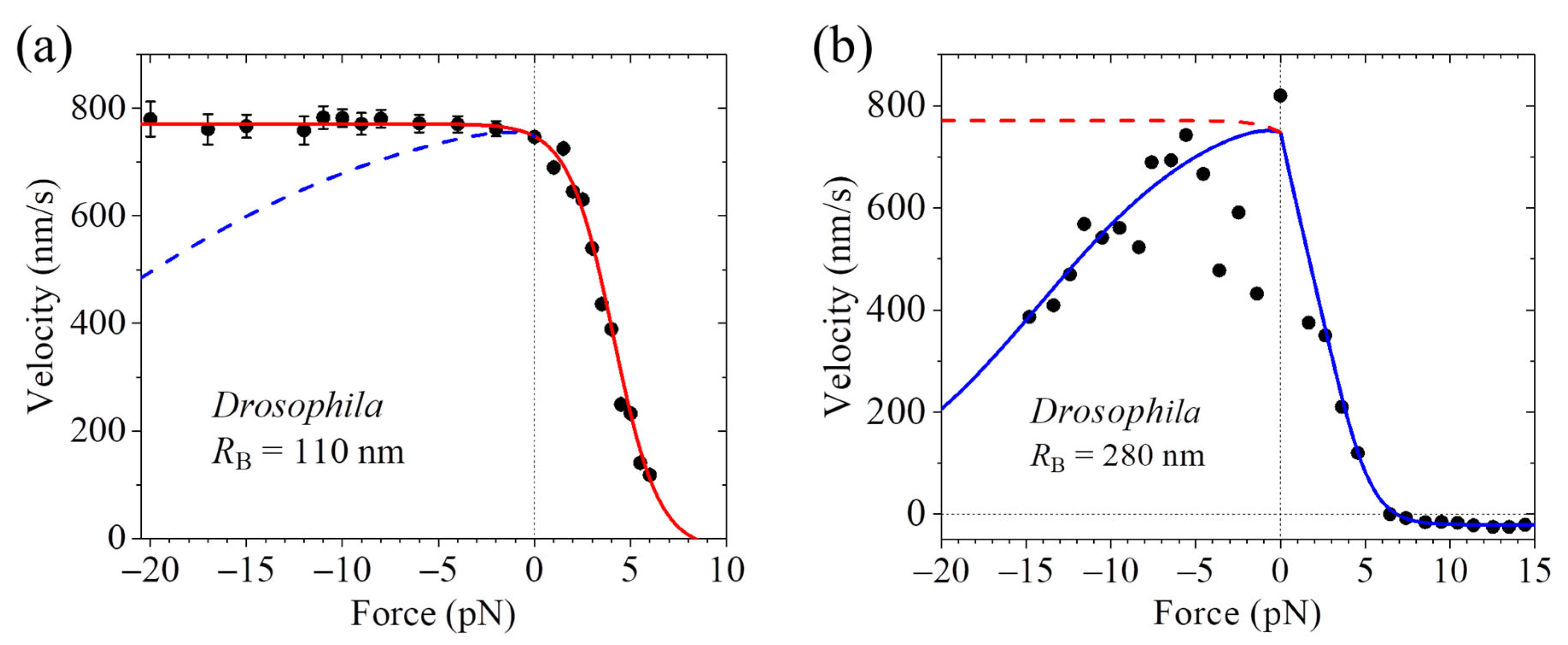
Some optical trapping assays obtained that the motor’s velocity is nearly independent on the forward load [37]. On the contrary, other optical trapping assays obtained that as the magnitude of the forward load increases, the velocity decreases slowly when the magnitude of the forward load is small and decreases quickly when the magnitude of the forward load is large [36,70]. In particular, for the same Drosophila kinesin, the assays by Andreasson et al. [37] obtained that the velocity is nearly independent on the forward load (Figure 3a), and by contrast, the assays by Carter and Cross [36] obtained that the velocity decreases as the magnitude of the forward load increases (Figure 3b).
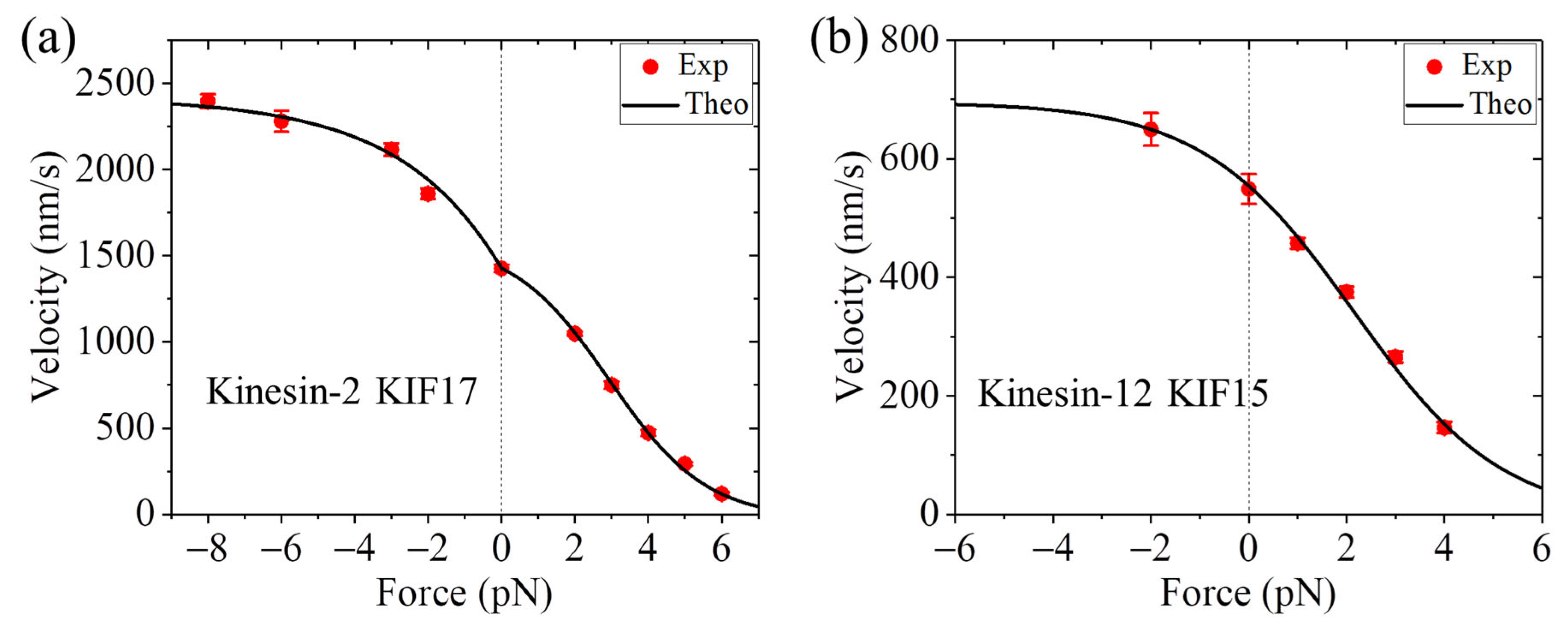
Additionally, it is noted that some optical trapping assays obtained that while for the human kinesin motor, the velocity is nearly independent on the forward load, for the corresponding mutant motor with the NL in each head being extended by adding six additional amino acids, the velocity increases as the magnitude of the forward load increases [37] (Figure 4). Interestingly, some optical trapping assays obtained that for some WT members of other kinesin families, such as KIF17 dimer of kinesin-2 family and KIF15 dimer of kinesin-12 family, the velocity also increases as the magnitude of the forward load increases [75,76] (Figure 5).
In summary, some optical trapping assays obtained that the velocity of the WT kinesin motor is nearly independent on the forward load [37], as shown in Figure 3a, whereas others obtained that the velocity of the WT kinesin motor decreases as the magnitude of the forward load increases [36,70], as shown in Figure 3b. The optical trapping assays obtained that while for the WT human kinesin motor, the velocity is nearly independent on the forward load, for the corresponding mutant motor with the NL extension, the velocity increases as the magnitude of the forward load increases [37], as shown in Figure 4. The optical trapping assays obtained that for some WT members of other kinesin families, such as KIF17 dimer of kinesin-2 family and KIF15 dimer of kinesin-12 family, the velocity also increases as the magnitude of the forward load increases [75,76], as shown in Figure 5.

5. Kinesin Pauses for a Short or Long Time upon Reaching Roadblocks

In cells, during the processive motion of a kinesin motor on MT, other MT-associated proteins can often bind to the MT, which act as roadblocks affecting the dynamics of the kinesin motor. Consequently, a lot of in vitro experimental studies have been performed on the dynamics of the kinesin motors with the presence of stationary roadblocks on MTs [79,80,81,82,83,84,85].
Most experimental results indicated that upon reaching the roadblock of a small size (e.g., the rigor-binding mutant of kinesin), the kinesin motor dissociates from MT after pausing for a short time of a few tens or hundreds of milliseconds [79,80,81], which is evidently shorter than the residence time of about 1 s on MT during the processive stepping in the absence of the roadblock [37]. The experimental results indicated that upon reaching the boundary of the tau cohesive islands, the kinesin motor also dissociates from MT rapidly, similar to reaching the small roadblock [86]. On the contrary, some experimental results indicated that upon reaching the roadblock of a large size (e.g., the 20 nm quantum dot, avidin, etc.), the kinesin motor can pause for a long time before dissociation, which is evidently longer than the residence time of about 1 s on MT in the absence of the roadblock [83,84,85].
Collectively, the experimental results indicated that different-sized roadblocks on the front tubulin have very different effects on the detachment of the kinesin motor from MT. The small roadblock accelerates the detachment [79,80,81,86], whereas the large roadblock hinders the detachment [83,84,85], which is counterintuitive.

6. Velocity Decreases Sensitively with or Depends Insensitively on the Solution Viscosity

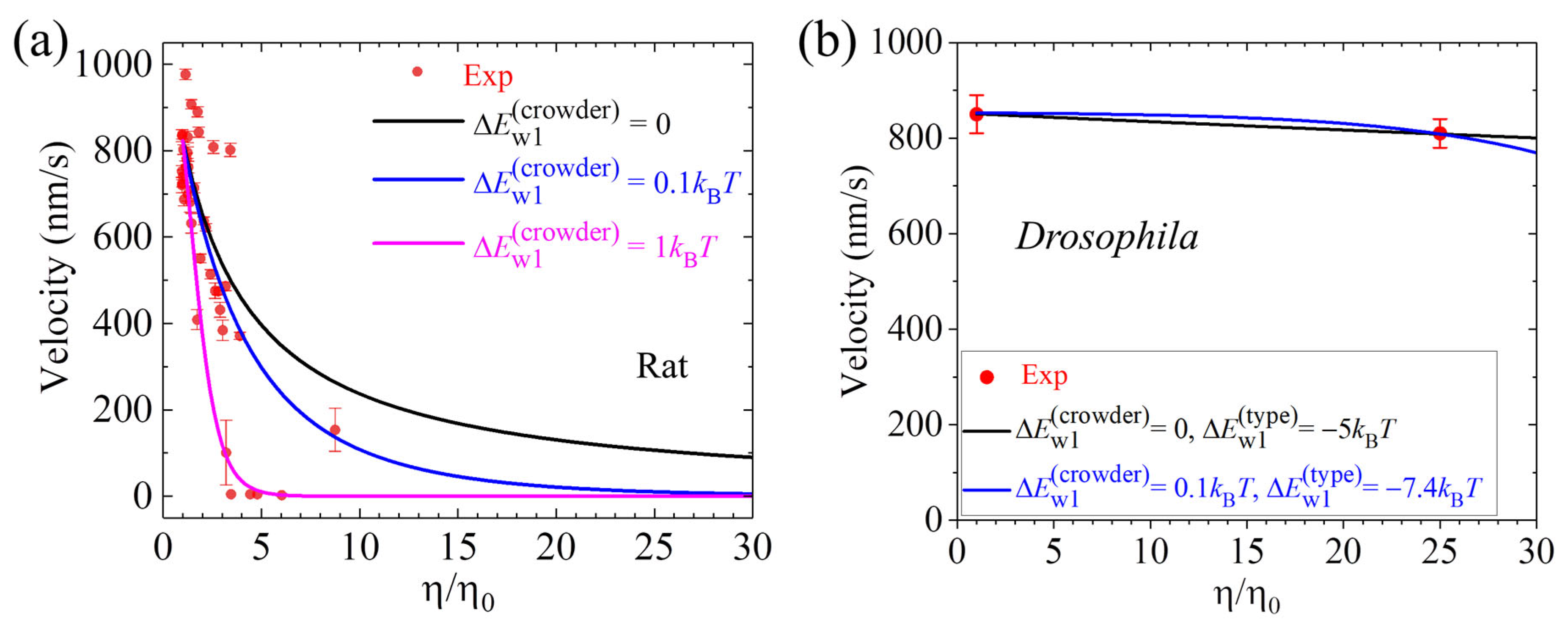
The influence of the solution viscosity on the velocity of the kinesin motor has been experimentally investigated by two research groups [87,88]. In the experiments by Sozanski et al. [87], the effective solution viscosity was varied by making use of various types, sizes, and/or concentrations of small molecular crowders including polyethylene glycol, dextrans, tetraethylene glycol, sucrose, and bovine serum albumin (BSA). In the experiments of Nettesheim et al. [88], the effective solution viscosity was varied by varying the concentration of BSA. Sozanski et al. [87] observed that, in general, the velocity of the rat kinesin significantly decreases as the effective viscosity increases (Figure 6a). For instance, increasing the viscosity by only about 3 times can decrease the velocity by about 1.6–8 times (Figure 6a). In contrast, Nettesheim et al. [88] observed that increasing the viscosity by 25 times has only a slight influence on the velocity of the Drosophila kinesin (Figure 6b).
Together, the experimental results of Sozanski et al. [87] showed that the velocity of the rat kinesin motor decreases sensitively with the increase in the effective viscosity, as shown in Figure 6a. In contrast, the experimental results of Nettesheim et al. [88] showed that the velocity of the Drosophila kinesin motor is insensitive to the increase in the effective viscosity, as shown in Figure 6b.

7. A Model Can Consistently Explain the Contrasting Experimental Results

In the literature, many models for the chemomechanical coupling of the kinesin motor have been presented, as reviewed elsewhere [56]. In general, those models can be categorized into two types. In one type of the models, it was proposed that the forward stepping of the motor is driven mainly by the NL docking caused by the ATP binding in the leading head [37,48,49,50,51,52], and thus these models were usually termed as the ‘NL-docking’ models [56]. In the other model, it was proposed that the stepping of the motor is achieved mainly by the Brownian ratchet mechanism, with the NL docking playing an assisting role [56,66,67,74,77,78], and thus this model was termed as the ‘Brownian Ratchet’ model [56]. In the NL-docking models, the dependence of the motor’s velocity on the load was explained to arise mainly from the dependence of the motor’s ATPase rate on the load [37,48,49,50,51,52]. Thus, with the NL-docking models, it is difficult to explain the contrasting results about the dependencies of the velocity on the backward load and on the forward load. It is also difficult to explain the decrease in the velocity with the increase in the solution viscosity, because the experimental data indicated that the ATPase rate is independent on the viscosity [87,88]. The counterintuitive experimental results showing that after reaching the large roadblock the pausing time of the motor before dissociation is much longer than after reaching the small roadblock are also difficult to explain.
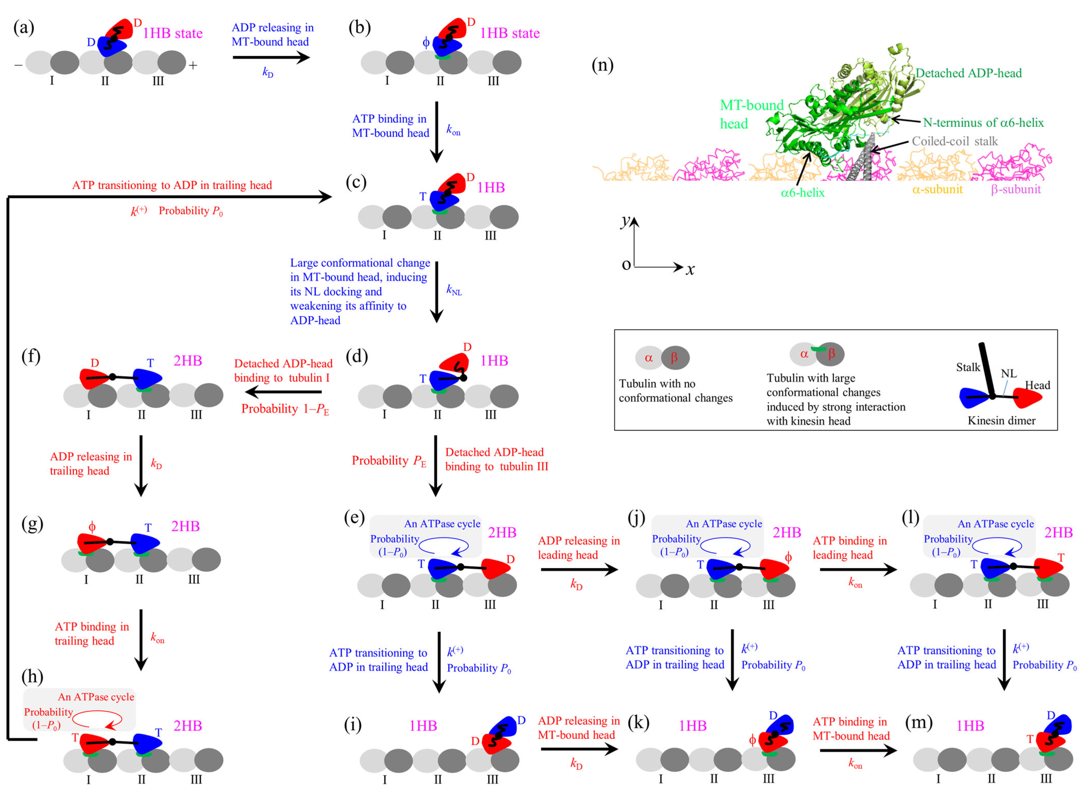
By contrast, it is noted that the Brownian Ratchet model can consistently explain the contrasting experimental results, as demonstrated before [66,67,74,77,78,89]. The model can be schematically shown in Figure 7 (see Appendix A for main elements, on the basis of which the model is set up). Because the rate of ATP transitioning to ADP in the leading head of its NL in the backward orientation is much lower than that in the trailing head of its NL in the forward orientation, for clarity, ATP transitioning to ADP in the leading head is not shown in Figure 7.
Let us start with one ADP-head binding to tubulin II with weak affinity Ew2 (defined in Appendix A) and the detached ADP-head having a high affinity for the MT-bound head (Figure 7a). The high affinity prevents the detached head from binding to MT. Activated by MT [91], ADP releases from the MT-bound head (Figure 7b). After ATP binding (Figure 7c), a large change in the conformation of the ATP-head, which is associated with the docking of its NL onto the head and the great reduction of its affinity for the detached head, takes place (Figure 7d). The detached head can with a probability PE diffuse forward rapidly (with a timescale of 1 μs) and bind to tubulin III with affinity Ew2 (Figure 7e) while with probability 1–PE diffuse backward and bind to tubulin I with affinity Ew2 by overcoming the energy barrier resulting from the large change in the conformation of the ATP-head and its NL docking (Figure 7f).
In Figure 7f, ADP releases from the trailing head (Figure 7g), followed by ATP binding (Figure 7h). After ATP transitioning to ADP in the trailing head, driven by the internal force resulting from the NL stretching and by overcoming the weak affinity Ew1 (Ew1 << Ew2, see Appendix A) for the local tubulin I, the ADP-head with probability P0 can detach and diffuse rapidly (with a timescale of 1 μs) to the intermediate (INT) position (Figure 7c). Accordingly, with probability 1–P0 the ADP-head cannot detach from or after detachment can rebind to tubulin I, followed by ADP releasing and ATP binding.
In Figure 7e, after ATP transitioning to ADP in the trailing head, with probability P0 the ADP-head can detach and diffuse rapidly to the INT position (Figure 7i), followed by ADP releasing from the MT-bound head (Figure 7k). In Figure 7e, ADP releases from the leading head (Figure 7j), followed by ATP binding (Figure 7l). In Figure 7j, after ATP transitioning to ADP in the trailing head, with probability P0 the ADP-head can detach and diffuse rapidly to the INT position (Figure 7k), followed by ATP binding to the ϕ-head (Figure 7m). In Figure 7l, after ATP transitioning to ADP in the trailing head, with probability P0 the ADP-head can detach and diffuse rapidly to the INT position (Figure 7m). Figure 7m is the same as Figure 7c, except that the motor makes a forward step in Figure 7m.
As the AMD simulation showed, in the 1HB state prior to the occurrence of the large change in the conformation of the MT-bound ATP-head, the detached ADP-head is at the leftward-, forward- and upward-biased position of the MT-bound head (Figure 7n) [90]. In the following, we briefly review how the model can consistently and quantitatively explain the contrasting experimental results. For convenience of writing, unless otherwise pointed out, from now on, the 1HB state refers to the one prior to the occurrence of the large change in the conformation of the MT-bound ATP-head.

7.1. Explanation of the Conflicting Experimental Results on ATP Binding in 1HB or 2HB State

The conflicting experimental results on ATP binding in the 1HB or 2HB state are briefly explained as follows [66]. Under no load, we have PE  1 and P0  1. The conflicting experimental results are due to distinct effects of the labeling on the interaction between the two heads in the 1HB state. In the experiment of Isojima et al. [27], the attachment of the particle to the amino acid at the rear position of one head via two polypeptide chains has no interference effect on the interaction between the two heads in the 1HB state, where the detached head is at the forward- and upward-biased position of the MT-bound head (Figure 7n). Thus, based on the pathway (Figure 7), the experimental results by Isojima et al. [27] can be theoretically reproduced (Figure 1a) [66,67]. In the experiment of Wolff et al. [28], the labeling of the 1 nm fluorophore at α6-helix C-terminus of one head also has no interference effect on the interaction between the two heads in the 1HB state. Thus, the experimental results by Wolff et al. [28] can also be theoretically reproduced (Figure 1c) [66]. In the experiment of Mickolajczyk et al. [26], the 30 nm particle that is attached to the center right of one head via a short linker of the contour length of only 2.91 nm can interfere with the interaction between the two heads in the 1HB state. The reduction in the affinity between the two heads can result in the detached ADP-head in the 1HB state of Figure 7k to bind to MT prior to ATP binding to the MT-bound head. Thus, this leads to ATP binding mainly in the 2HB state. With this consideration, the experimental results by Mickolajczyk et al. [26] can be theoretically reproduced [66] (Figure 1b).

7.2. Explanation of the Contrasting Experimental Results on Velocity Versus Backward Load

The contrasting experimental results on the velocity versus backward load are briefly explained as follows [74]. Because in the optical trapping assays, the trap is kept stationary using the fixed trap whereas the trap can be movable using the movable trap, it is expected that the fluctuation of the trap relative to the bead for the fixed trap is generally smaller than that for the movable trap, inducing the deviation of the position of the kinesin-bead complex relative to the trap from the equilibrium position for the former to be small than that for the latter. This results in that the force-sensitivity distance for the ADP-head to diffuse from the rear tubulin to the INT position (e.g., the transition from Figure 7e–i) for the fixed trap is larger than that for the movable trap, giving P0 < 1 for the former and P0  1 for the latter under the backward load. P0 can be approximately written as P 0 = exp β F Δ 1 , where β 1 = k B T is the Boltzmann constant times the absolute temperature, F is the backward load, and Δ 1 is the force-sensitivity distance, with Δ 1 0 for the movable trap and Δ 1 having a non-zero small value ( 1 nm) for the fixed trap [74]. P0 < 1 leads to the velocity decreasing quicker with the backward load than P0  1. Thus, while the velocity versus backward load with P0  1 has the sigmoid form (Figure 2a,b), with P0 < 1 has the nearly linear form (Figure 2c,d) [74].

7.3. Explanation of the Contrasting Experimental Results on Velocity Versus Forward Load

The contrasting experimental results on the velocity of kinesin-1 versus forward load are briefly explained as follows [74]. Under no or forward load, we have PE  1 and P0  1. In the optical trapping assays, MT is fixed to the stage surface and the kinesin with its stalk attached to the large-sized bead is bound to MT. The contrasting experimental results are due to distinct positions of the kinesin on MT. One case (Case I) is that the motor is on the left side of MT (viewed in the plus-ended direction) and the other case (Case II) is that the motor is on the upper side, where the bottom side contacts the stage surface (Figure 8). In the 1HB state, since the detached head is at the forward-biased position of the MT-bound head (Figure 7n), the backward and forward loads on the stalk acts mainly on NLs of the detached and MT-bound heads, respectively. The structural studies demonstrated that the large change of the conformation of the head in ATP state relative to that in ϕ state involves a large-scale rotation of α6 helix relative to α4 helix binding to MT, with α6-helix C-terminus moving leftward for a large distance [17,18,19,20,44,92]. Thus, for Case I (Figure 8a), the forward load on the bead, giving a rightward component (z-component) of the load on the stalk that points rightward, can reduce the rate (kNL) of the leftward movement of α6-helix C-terminus; namely, the large change in the conformation of the MT-bound ATP-head and its NL docking [74]. In contrast, for Case II (Figure 8b) the forward load, giving no rightward component (z-component) on the stalk that points upward, has no effect on kNL [74]. Therefore, for Case I, the decrease in kNL with the forward load results in the decrease in the velocity, whereas for Case II, the velocity is nearly independent on the forward load (Figure 3) [74].
The experimental results that the velocity of the WT human kinesin-1 is nearly independent on the forward load, whereas that of the mutant one with the extended NLs increases with the forward load, are briefly explained as follows [77]. For the mutant kinesin-1, we still have PE  1 under no or forward load. However, due to the NL extension, the internal force between the two heads in the 2HB state becomes nearly zero, leading to P0 < 1 under no load. Thus, for Case II the velocity increases with the forward load because P0 increases with the forward load (Figure 4) [77]. Additionally, under no load, PE  1 and P0  1 for the WT kinesin-1 give nearly one ATP consumed per step whereas PE  1 and P0 < 1 for the mutant kinesin-1 give multiple ATPs consumed per step [77], which are consistent with the experimental results [93,94]. As for the mutant kinesin-1, for the kinesin-2 KIF17 and kinesin-12 KIF15, it is also considered that P0 < 1 under no load, although PE  1 under no or forward load [78]. Thus, the velocities of KIF17 and KIF15 also increase with the forward load for Case II (Figure 5) [78].

7.4. Explanation of the Conflicting Experimental Results on Pausing Time upon Reaching Roadblocks

The conflicting experimental results on kinesin pausing for a short or long time upon reaching a roadblock are briefly explained as follows. It was shown that with the front tubulin III in Figure 7 being occupied by a small roadblock, the residence time of the kinesin motor on MT is determined mainly by the occurrence probability of the event that ATP transitioning to ADP in the MT-bound head takes place before the detached ADP-head binding to the rear tubulin I [95]. If the event occurs, the period (called Period I) occurs when the MT-bound head has the very weak affinity Ew1 for the local tubulin and the other head is detached from MT, during which the motor can dissociate easily from MT (Figure 9). The conflicting experimental results arise from different-sized roadblocks on the front tubulin having different interference effects on the location of the detached head relative to the MT-bound head in the 1HB state.
The small roadblock has no interference effect on the location of the detached head relative to the MT-bound head in the 1HB state (Figure 9a) [95]. Before NL docking of the MT-bound head (Figure 9a), due to the very low rate of ATP transitioning to ADP, Period I can occur with a low rate (Figure 9, transition from Figure 9a–e). After NL docking of the MT-bound head (Figure 9b), due to the high rate of ATP transitioning to ADP, Period I can occur with a high rate (Figure 9, transition from Figure 9b–e). Hence, the kinesin motor has a short residence time on MT. By contrast, the large roadblock can have an interference effect on the relative location of the detached ADP-head to the MT-bound head in the 1HB state (Figure 9a’), because the detached head is at the forward- and upward-biased position of the MT-bound head. Consequently, in the 1HB state, the detached ADP-head cannot have the high affinity for the MT-bound head (Figure 9a’) and thus the detached ADP-head can bind to the rear tubulin before the large change in the conformation of the MT-bound ATP-head associated with its NL docking (Figure 9b’). Due to the very low rate of ATP transitioning to ADP in the MT-bound head prior to its NL docking, Period I can occur with a low rate (Figure 9, transition from Figure 9a’–d’). Hence, the kinesin motor has a long residence time on MT.

7.5. Explanation of the Conflicting Experimental Results on Dependence of Velocity Upon Solution Viscosity

The conflicting experimental results on the velocity versus solution viscosity are briefly explained as follows [89]. The experimental results indicated that the presence of the small crowders in the solution has little influence on the ATPase activity of the kinesin motor [87,88]. Under no load, we have PE  1 in either absence or presence of the crowders. As noted above, we have P0  1 under no load in the absence of the crowders. The presence of the crowders increases the effective viscosity [87,88]. Moreover, the crowders can alter slightly the interaction of the head with MT, with the affinity Ew1 being increased by a few kBT. Either the increase in the viscosity or the increase in the affinity Ew1 can induce P0 < 1. Thus, the experimental results by Sozanski et al. [87] showing that the velocity of the rat kinesin decreases significantly as the effective viscosity increases can be explained (Figure 6a) [89]. By considering that the affinity Ew1 for the Drosophila kinesin is smaller than that for the rat kinesin, the experimental results by Nettesheim et al. [88] showing that increasing the viscosity by 25 times has only a slight influence on the velocity of the Drosophila kinesin can also be explained (Figure 6b) [89].

7.6. Explanation of Other Experimental Results

The model can also explain well other experimental results about the dynamics of the kinesin motors [55,56,57,58,77,78,96]. For instance, the experimental results about dependencies of the run length and dissociation rate on both backward and forward loads for members of different families such as kinesin-1, kinesin-5 Eg5, kinesin-12 KIF15, kinesin-2 KIF17, kinesin-2 KIF3AB, etc., were explained [78]. The perplexing experimental results about bidirectional motions of some kinesin-5 dimers such as S. cerevisiae Cin8 and Kip1 and S. pombe Cut7, with the direction depending on the experimental condition albeit with the NL always docking in the forward orientation [97,98,99,100,101], were explained [102]. The puzzling experimental results for orphan kinesin PAKRP2 having a long NL of 32 amino acids in each head, which like kinesin-1 can also move hand-over-hand by hydrolyzing one ATP per step [103], were explained [104]. The experimental results about some families of kinesin dimers such as kinesin-1, kinesin-2, and kinesin-5 moving on MT in the predominant 2HB state under saturating ATP concentrations [17,39,65,105], whereas others such as kinesin-3 and kinesin-13 moving in the predominant 1HB state [106,107,108], were explained [67,109]. The experimental results about the dynamics of motors with various mutations, such as the deletion or mutation of the N-terminus cover strand contributing to the NL docking in kinesin-1 [35], the NL extension in kinesin-1 [37], the NL mutation in kinesin-1 [110], the swapping of NL in kinesin-2 with that in kinesin-1 [111], the joining of the stalk and neck of kinesin-14 Ncd to the head of kinesin-1 [112], the replacement of the head of kinesin-1 with that of Ncd [113], etc., were explained [77]. The perplexing experimental results showing that the transport of cargo by two or multiple kinesin monomers with short truncated stalks connecting to the cargo behaves as efficiently as that by one or multiple kinesin dimers [114,115] were explained using the similar model [116].

8. Concluding Remarks and Future Perspectives

Here, a brief review of diverse contrasting experimental results about the dynamics of the kinesin motor is presented. The contrasting experimental results include (1) those on whether ATP binding occurs in the 1HB or 2HB state, (2) those on whether the velocity versus backward load has a sigmoid or linear form, (3) those on whether the velocity decreases with or is nearly independent on or increases with the forward load, (4) those on whether the motor pauses for a short or long time upon reaching a stationary roadblock, and (5) those on whether the velocity decreases sensitively with or is insensitive to the increase in the solution viscosity. Furthermore, a model for the chemomechanical coupling of the kinesin motor (Figure 7) is briefly reviewed, which can consistently explain these contrasting experimental results as well as other experimental results. A consistent explanation of the diverse contrasting experimental results with one model is an essential criterion for determining whether the model is correct or not for the chemomechanical coupling mechanism of the kinesin motor.
A peculiar characteristic for the model of Figure 7 is that for the WT kinesin motor, while under no or low backward loads, approximately one ATP is consumed per forward step; under the medium or large backward loads, multiple ATPs are consumed per forward step. Based on the model of Figure 7, for the rat kinesin motor, the reduced velocity under the increased viscosity and under no load (Figure 6a) is due to the increased futile chemomechanical cycles or increased number of ATPs hydrolyzed per forward step. Based on the model of Figure 7, it is predicted that after reaching a roadblock, multiple ATPs are hydrolyzed before dissociation and, moreover, after reaching the large roadblock, much more ATPs are hydrolyzed than after reaching the small roadblock. To further confirm the validity of the model of Figure 7, it is hoped to test these predictions through future experiments.

Funding

No funding.

Institutional Review Board Statement

Not applicable.

Informed Consent Statement

Not applicable.

Data Availability Statement

Data sharing is not applicable to this article as no datasets were generated or analyzed during the current study.

Acknowledgments

No GenAI tools were used during the manuscript preparation.

Conflicts of Interest

The author declares no conflicts of interest.

Abbreviations

ADPadenosine diphosphate
AMDatomistic molecular dynamics
ATPadenosine triphosphate
ATPaseadenosine triphosphatase
BSAbovine serum albumin
ϕnucleotide free
INTintermediate
MTmicrotubule
NBPnucleotide-binding pocket
NLneck linker
1HBone-head-bound
2HBtwo-heads-bound
WTwild type

Appendix A. Main Elements in the Model of Figure 7

The main elements, which are derived from the published structural, biochemical, and AMD simulation studies and on the basis of which the model of Figure 7 is set up, are summarized as follows.
Interaction between kinesin head and MT—The head in ϕ and ATP (ATP representing both ATP and ADP.Pi) states shows a strong interaction, whereas in the ADP state shows a weak interaction with MT [12,117,118]. The strong interaction induces large conformational changes, whereas the weak interaction induces little conformational changes of the local tubulin on MT, as shown by cryo-electron microscopic structural studies [21,119] and by AMD simulation studies [120]. The ADP-head shows a much weaker affinity (Ew1) for the tubulin having the large conformational changes than the affinity (Ew2) for the tubulin having little conformational changes, as indicated by AMD simulation studies [120,121]. Thus, it is expected that after ATP transitioning to ADP in the MT-bound head, there exists a short time tr (with the timescale of 10 μs) when the ADP-head shows affinity Ew1 for the local tubulin and in time tr the local tubulin returns elastically to the normally unchanged form, with the affinity of the ADP-head for the local tubulin transitioning from Ew1 to Ew2 [55,104]. The evidence that kinesin binding can induce the conformational changes of MT, in turn affecting the affinity of kinesin for the MT, is also supported by the fact that the kinesin binding can affect the binding of other kinesins to the MT [119,122,123,124] and particularly the velocity and run time of a kinesin-4 motor can be largely influenced by other distant kinesins on the MT [125], which can be explained by the propagation of the MT conformational changes along the MT [126].
Nucleotide-dependent conformation of the kinesin head and its interaction with the partner head—In ADP and ϕ states, the head possesses the conformation, having an open nucleotide-binding pocket (NBP) and an NL incapable of docking onto the head, as indicated by structural and experimental studies [17,18,127,128,129], and with the head showing a large affinity for the partner ADP-head, as indicated by AMD simulation studies [90]. In the ATP state, the NBP closing and a large change in the conformation of the head can take place, so that NL becomes capable of docking onto the head, as indicated by structural and experimental studies [17,18,127,128,129], and the affinity of the head for the partner ADP-head decreases largely, as indicated by AMD simulation studies [90]. NL driven in the backward orientation inhibits the NBP closing and the large change in the conformation of the ATP-head [130,131].
ATPase activity of kinesin head—The rate of ATP transitioning to ADP in the head of its NL in the forward orientation is much larger than that of its NL not in the forward orientation, which is supported by the following structural and experimental evidence. The structural studies indicated that NL in the forward orientation clashes with a nucleotide-binding motif (a P-loop subdomain) in the ϕ-orientation, implying that the P-loop subdomain is in the ATP-like orientation [20], which should significantly increase the rate of ATP transitioning to ADP. This is in accordance with the experimental results showing that the mutation or deletion of the NL of the kinesin-1 or kinesin-3 KIF1A head significantly reduces the ATPase rate while it has no effect on the ADP-release rate [20,132], because after ATP binding, NL docks rapidly in the forward orientation. Moreover, the rate of ATP transitioning to ADP in the head is independent on the force acting on its NL. This is consistent with the experimental evidence that extending NLs has little effect on the ATPase rate of the kinesin-1 dimer [93] and the ATPase rate of the truncated kinesin-1 monomer is nearly equal to that of the dimer [24,133,134], because extending NLs largely reduces the stretching force on the NLs of the dimer in the 2HB state [37,55,135] and no stretching force is present on the NL of the monomer.

References

  1. Lawrence, C.J.; Dawe, R.K.; Christie, K.R.; Cleveland, D.W.; Dawson, S.C.; Endow, S.A.; Goldstein, L.S.B.; Goodson, H.V.; Hirokawa, N.; Howard, J.; et al. A standardized kinesin nomenclature. J. Cell Biol. 2004, 167, 19–22. [Google Scholar] [CrossRef] [PubMed]
  2. Vale, R.D. The molecular motor toolbox for intracellular transport. Cell 2003, 112, 467–480. [Google Scholar] [CrossRef] [PubMed]
  3. Miki, H.; Okada, Y.; Hirokawa, N. Analysis of the kinesin superfamily: Insights into structure and function. Trends Cell Biol. 2005, 15, 467–476. [Google Scholar] [CrossRef] [PubMed]
  4. Hirokawa, N.; Noda, Y.; Tanaka, Y.; Niwa, S. Kinesin superfamily motor proteins and intracellular transport. Nat. Rev. Mol. Cell Biol. 2009, 10, 682. [Google Scholar] [CrossRef]
  5. Iino, R.; Kinbara, K.; Bryant, Z. Introduction: Molecular motors. Chem. Rev. 2020, 120, 1–4. [Google Scholar] [CrossRef]
  6. Vale, R.D.; Reese, T.S.; Sheetz, M.P. Identification of a novel force-generating protein, kinesin, involved in microtubule-based motility. Cell 1985, 42, 39–50. [Google Scholar] [CrossRef]
  7. Brady, S.T. A novel brain ATPase with properties expected for the fast axonal transport motor. Nature 1985, 317, 73–75. [Google Scholar] [CrossRef]
  8. Howard, J. The movement of kinesin along microtubules. Annu. Rev. Physiol. 1996, 58, 703–729. [Google Scholar] [CrossRef]
  9. Cross, R.A. The kinetic mechanism of kinesin. Trends Biochem. Sci. 2004, 29, 301–309. [Google Scholar] [CrossRef]
  10. Asbury, C.L. Kinesin: World’s tiniest biped. Curr. Opin. Cell Biol. 2005, 17, 89–97. [Google Scholar]
  11. Block, S.M. Kinesin motor mechanics: Binding, stepping, tracking, gating, and limping. Biophys. J. 2007, 92, 2986–2995. [Google Scholar] [CrossRef] [PubMed]
  12. Cross, R.A. Mechanochemistry of the kinesin-1 ATPase. Biopolymers 2017, 105, 476–482. [Google Scholar] [CrossRef]
  13. Kozielski, F.; Sack, S.; Marx, A.; Thormählen, M.; Schönbrunn, E.; Biou, V.; Thompson, A.; Mandelkow, E.M.; Mandelkow, E. The crystal structure of dimeric kinesin and implications for microtubule-dependent motility. Cell 1997, 91, 985–994. [Google Scholar] [CrossRef]
  14. Block, S.M.; Goldstein, L.S.; Schnapp, B.J. Bead movement by single kinesin molecules studied with optical tweezers. Nature 1990, 348, 348–352. [Google Scholar] [CrossRef]
  15. Svoboda, K.; Schmidt, C.; Schnapp, B.; Block, S. Direct observation of kinesin stepping by optical trapping interferometry. Nature 1993, 365, 721–727. [Google Scholar] [CrossRef]
  16. Kull, F.J.; Sablin, E.P.; Lau, R.; Fletterick, R.J.; Vale, R.D. Crystal structure of the kinesin motor domain reveals a structural similarity to myosin. Nature 1996, 380, 550–555. [Google Scholar] [CrossRef] [PubMed]
  17. Sindelar, C.V.; Downing, K.H. An atomic-level mechanism for activation of the kinesin molecular motors. Proc. Natl. Acad. Sci. USA 2010, 107, 4111–4116. [Google Scholar] [CrossRef] [PubMed]
  18. Shang, Z.; Zhou, K.; Xu, C.; Csencsits, R.; Cochran, J.C.; Sindelar, C.V. High-resolution structures of kinesin on microtubules provide a basis for nucleotide-gated force-generation. eLife 2014, 3, e04686. [Google Scholar] [CrossRef]
  19. Gigant, B.; Wang, W.; Dreier, B.; Jiang, Q.; Pecqueur, L.; Plückthun, A.; Wang, C.; Knossow, M. Structure of a kinesin-tubulin complex and implications for kinesin motility. Nat. Struct. Mol. Biol. 2013, 20, 1001–1007. [Google Scholar] [CrossRef]
  20. Cao, L.; Wang, W.; Jiang, Q.; Wang, C.; Knossow, M.; Gigant, B. The structure of apo-kinesin bound to tubulin links the nucleotide cycle to movement. Nat. Comm. 2014, 5, 5364. [Google Scholar] [CrossRef] [PubMed]
  21. Morikawa, M.; Yajima, H.; Nitta, R.; Inoue, S.; Ogura, T.; Sato, C.; Hirokawa, N. X-ray and Cryo-EM structures reveal mutual conformational changes of kinesin and GTP-state microtubules upon binding. EMBO J. 2015, 34, 1270–1286. [Google Scholar] [CrossRef]
  22. Hackney, D.D. Evidence for alternating head catalysis by kinesin during microtubule-stimulated ATP hydrolysis. Proc. Natl. Acad. Sci. USA 1994, 91, 6865–6869. [Google Scholar] [CrossRef]
  23. Hackney, D.D. Kinesin ATPase: Rate-limiting ADP release. Proc. Natl. Acad. Sci. USA 1998, 37, 800–813. [Google Scholar] [CrossRef]
  24. Moyer, M.L.; Gilbert, S.P.; Johnson, K.A. Pathway of ATP hydrolysis by monomeric and dimeric kinesin. Biochemistry 1998, 37, 800–813. [Google Scholar] [CrossRef]
  25. Rosenfeld, S.S.; Jefferson, G.M.; King, P.H. ATP reorients the neck linker of kinesin in two sequential steps. J. Biol. Chem. 2001, 276, 40167–40174. [Google Scholar] [CrossRef]
  26. Mickolajczyk, K.J.; Deffenbaugh, N.C.; Arroyo, J.O.; Andrecka, J.; Kukura, P.; Hancock, W.O. Kinetics of nucleotide-dependent structural transitions in the kinesin-1 hydrolysis cycle. Proc. Natl. Acad. Sci. USA 2015, 112, E7186–E7193. [Google Scholar] [CrossRef] [PubMed]
  27. Isojima, H.; Iino, R.; Niitani, Y.; Noji, H.; Tomishige, M. Direct observation of intermediate states during the stepping motion of kinesin-1. Nat. Chem. Biol. 2016, 12, 290–297. [Google Scholar] [CrossRef] [PubMed]
  28. Wolff, J.O.; Scheiderer, L.; Engelhardt, T.; Engelhardt, J.; Matthias, J.; Hell, S.W. MINFLUX dissects the unimpeded walking of kinesin-1. Science 2023, 379, 1004–1010. [Google Scholar] [CrossRef]
  29. Deguchi, T.; Iwanski, M.K.; Schentarra, E.-M.; Heidebrecht, C.; Schmidt, L.; Heck, J.; Weihs, T.; Schnorrenberg, S.; Hoess, P.; Liu, S.; et al. Direct observation of motor protein stepping in living cells using MINFLUX. Science 2023, 379, 1010–1015. [Google Scholar] [CrossRef]
  30. Schnitzer, M.J.; Block, S.M. Kinesin hydrolyses one ATP per 8-nm step. Nature 1997, 388, 386–390. [Google Scholar] [CrossRef] [PubMed]
  31. Coppin, C.M.; Pierce, D.W.; Hsu, L.; Vale, R.D. The load dependence of kinesin’s mechanical cycle. Proc. Natl. Acad. Sci. USA. 1997, 94, 8539–8544. [Google Scholar] [CrossRef]
  32. Kojima, H.; Muto, E.; Higuchi, H.; Yanagida, T. Mechanics of single kinesin molecules measured by optical trapping nanometry. Biophys. J. 1997, 73, 2012–2022. [Google Scholar] [CrossRef]
  33. Visscher, K.; Schnitzer, M.J.; Block, S.M. Single kinesin molecules studied with a molecular force clamp. Nature 1999, 400, 184–189. [Google Scholar] [CrossRef] [PubMed]
  34. Nishiyama, M.; Higuchi, H.; Yanagida, T. Chemomechanical coupling of the forward and backward steps of single kinesin molecules. Nat. Cell Biol. 2002, 4, 790–797. [Google Scholar] [CrossRef] [PubMed]
  35. Khalil, A.S.; Appleyard, D.C.; Labno, A.K.; Georges, A.; Karplus, M.; Belcher, A.M.; Hwang, W.; Lang, M.J. Kinesin’s cover-neck bundle folds forward to generate force. Proc. Natl. Acad. Sci. USA 2008, 105, 19247–19252. [Google Scholar] [CrossRef]
  36. Carter, N.J.; Cross, R.A. Mechanics of the kinesin step. Nature 2005, 435, 308–312. [Google Scholar] [CrossRef]
  37. Andreasson, J.O.L.; Milic, B.; Chen, G.-Y.; Guydosh, N.R.; Hancock, W.O.; Block, S.M. Examining kinesin processivity within a general gating framework. eLife 2015, 4, e07403. [Google Scholar] [CrossRef] [PubMed]
  38. Milic, B.; Andreasson, J.O.L.; Hancock, W.O.; Block, S.M. Kinesin processivity is gated by phosphate release. Proc. Natl. Acad. Sci. USA 2014, 111, 14136–14140. [Google Scholar] [CrossRef]
  39. Sudhakar, S.; Abdosamadi, M.K.; Jachowski, T.J.; Bugiel, M.; Jannasch, A.; Schäffer, E. Germanium nanospheres for ultraresolution picotensiometry of kinesin motors. Science 2021, 71, eabd9944. [Google Scholar] [CrossRef]
  40. Hyeon, C.; Onuchic, J.N. Mechanical control of the directional stepping dynamics of the kinesin motor. Proc. Natl. Acad. Sci. USA 2007, 104, 17382–17387. [Google Scholar] [CrossRef]
  41. Zhang, Z.; Thirumalai, D. Dissecting the kinematics of the kinesin step. Structure 2012, 20, 628–640. [Google Scholar] [CrossRef] [PubMed]
  42. Kanada, R.; Kuwata, T.; Kenzaki, H.; Takada, S. Structure-based molecular simulations reveal the enhancement of biased Brownian motions in single-headed kinesin. PLoS Comput. Biol. 2013, 9, e1002907. [Google Scholar] [CrossRef]
  43. Hwang, W.; Lang, M.J.; Karplus, M. Force generation in Kinesin hinges on cover-neck bundle formation. Structure 2008, 16, 62–71. [Google Scholar] [CrossRef]
  44. Geng, Y.-Z.; Ji, Q.; Liu, S.-X.; Yan, S.-W. Initial conformation of kinesin’s neck linker. Chin. Phys. B 2014, 23, 108701. [Google Scholar] [CrossRef]
  45. Chakraborty, S.; Zheng, W. Decrypting the structural, dynamic, and energetic basis of a monomeric Kinesin interacting with a tubulin dimer in three ATPase states by all-atom molecular dynamics simulation. Biochemistry 2015, 54, 859–869. [Google Scholar] [CrossRef]
  46. Wang, J.-G.; Shi, X.-X.; Liu, Y.-R.; Wang, P.-Y.; Chen, H.; Xie, P. Investigation of the structural and dynamic basis of kinesin dissociation from microtubule by atomistic molecular dynamics simulations. Chin. Phys. B 2022, 31, 058702. [Google Scholar] [CrossRef]
  47. Geng, Y.-Z.; Lu, L.-A.; Jia, N.; Zhang, B.-B.; Ji, Q. Kinesin-microtubule interaction reveals the mechanism of kinesin-1 for discriminating the binding site on microtubule. Chin. Phys. B 2023, 32, 108701. [Google Scholar] [CrossRef]
  48. Schnitzer, M.J.; Visscher, K.; Block, S.M. Force production by single kinesin motors. Nat. Cell Biol. 2000, 2, 718–723. [Google Scholar] [CrossRef]
  49. Fisher, M.E.; Kolomeisky, A.B. Simple mechanochemistry describes the dynamics of kinesin molecules. Proc. Natl. Acad. Sci. USA 2001, 98, 7748–7753. [Google Scholar] [CrossRef] [PubMed]
  50. Hyeon, C.; Onuchic, J.N. Internal strain regulates the nucleotide binding site of the kinesin leading head. Proc. Natl. Acad. Sci. USA 2007, 104, 2175–2180. [Google Scholar] [CrossRef] [PubMed]
  51. Liepelt, S.; Lipowsky, R. Kinesin’s network of chemomechanical motor cycles. Phys. Rev. Lett. 2007, 98, 258102. [Google Scholar] [CrossRef]
  52. Khataee, H.; Liew, A.W.C. A mathematical model describing the mechanical kinetics of kinesin stepping. Bioinformatics 2014, 30, 353–359. [Google Scholar]
  53. Sumi, T. Design principles governing chemomechanical coupling of kinesin. Sci. Rep. 2017, 7, 1163. [Google Scholar] [CrossRef]
  54. Takaki, R.; Mugnai, M.L.; Goldtzvik, Y.; Thirumalai, D. How kinesin waits for ATP affects the nucleotide and load dependence of the stepping kinetics. Proc. Natl. Acad. Sci. USA 2019, 116, 23091–23099. [Google Scholar] [CrossRef]
  55. Guo, S.-K.; Wang, P.-Y.; Xie, P. A model of processive movement of dimeric kinesin. J. Theor. Biol. 2017, 414, 62–75. [Google Scholar] [CrossRef]
  56. Xie, P. Insight into the chemomechanical coupling mechanism of kinesin molecular motors. Commun. Theor. Phys. 2021, 73, 057601. [Google Scholar] [CrossRef]
  57. Liu, Y.; Zhang, Z. Origin of tradeoff between movement velocity and attachment duration of kinesin motor on microtubule. Chin. Phys. B 2024, 33, 028708. [Google Scholar] [CrossRef]
  58. Shi, X.; Wang, Y.; Liu, Y.; Xie, P. On load dependence of detachment rate of kinesin motor. Chin. Phys. B 2025, 34, 018702. [Google Scholar] [CrossRef]
  59. Asbury, C.L.; Fehr, A.N.; Block, S.M. Kinesin moves by an asymmetric hand-over-hand mechanism. Science 2003, 302, 2130–2134. [Google Scholar] [PubMed]
  60. Yildiz, A.; Tomishige, M.; Vale, R.D.; Selvin, P.R. Kinesin walks hand-over-hand. Science 2004, 303, 676–678. [Google Scholar] [CrossRef] [PubMed]
  61. Toleikis, A.; Carter, N.J.; Cross, R.A. Backstepping mechanism of kinesin-1. Biophys J. 2020, 119, 1984–1994. [Google Scholar] [CrossRef]
  62. Kondo, Y.; Kazuo Sasaki, K.; Higuchi, H. Fast backward steps and detachment of single kinesin molecules measured under a wide range of loads. Traffic 2023, 24, 463–474. [Google Scholar] [CrossRef]
  63. Mori, T.; Vale, R.D.; Tomishige, M. How kinesin waits between steps. Nature 2007, 450, 750–754. [Google Scholar] [CrossRef]
  64. Alonso, M.C.; Drummond, D.R.; Kain, S.; Hoeng, J.; Amos, L.; Cross, R.A. An ATP gate controls tubulin binding by the tethered head of kinesin-1. Science 2007, 316, 120–123. [Google Scholar] [CrossRef]
  65. Chen, G.-Y.; Mickolajczyk, K.J.; Hancock, W.O. The kinesin-5 chemomechanical cycle is dominated by a two-heads-bound state. J. Biol. Chem. 2016, 291, 20283–20294. [Google Scholar] [CrossRef]
  66. Xie, P. ATP-concentration-dependent fractions of one-head-bound and two-heads-bound states of kinesin motor during its chemomechanical coupling cycle. J. Phys. Chem. Lett. 2024, 15, 3893–3899. [Google Scholar] [CrossRef]
  67. Shi, X.-X.; Liu, Y.-R.; Xie, P. Factors determining kinesin motor in a predominant one-head-bound or two-heads-bound state during its stepping cycle. Biomolecules 2025, 15, 717. [Google Scholar] [CrossRef]
  68. Higuchi, H.; Muto, E.; Inoue, Y.; Yanagida, T. Kinetics of force generation by single kinesin molecules activated by laser photolysis of caged ATP. Proc. Natl. Acad. Sci. USA 1997, 94, 4395–4400. [Google Scholar] [CrossRef] [PubMed]
  69. Visscher, K.; Block, S.M. Versatile optical traps with feedback control. Methods Enzymol. 1998, 298, 460–489. [Google Scholar] [PubMed]
  70. Block, S.M.; Asbury, C.L.; Shaevitz, J.W.; Lang, M.J. Probing the kinesin reaction cycle with a 2D optical force clamp. Proc. Natl. Acad. Sci. USA 2003, 100, 2351–2356. [Google Scholar] [CrossRef] [PubMed]
  71. Kaseda, K.; Higuchi, H.; Horose, K. Coordination of kinesin’s two heads studied with mutant heterodimers. Proc. Natl. Acad. Sci. USA 2002, 99, 16058–16063. [Google Scholar] [CrossRef]
  72. Svoboda, K.; Block, S.M. Force and velocity measured for single kinesin molecules. Cell 1994, 77, 773–784. [Google Scholar] [CrossRef] [PubMed]
  73. Kawaguchi, K.; Ishiwata, S. Temperature dependence of force, velocity, and processivity of single kinesin molecules. Biochem. Biophys. Res. Commun. 2000, 272, 895–899. [Google Scholar] [CrossRef]
  74. Xie, P. Effects of stalk orientation and size of trapped bead on force–velocity relation of kinesin motor determined using single molecule optical trapping methods. J. Biol. Phys. 2025, 51, 7. [Google Scholar] [CrossRef]
  75. Milic, B.; Andreasson, J.O.L.; Hogan, D.W.; Block, S.M. Intraflagellar transport velocity is governed by the number of active KIF17 and KIF3AB motors and their motility properties under load. Proc. Natl. Acad. Sci. USA 2017, 114, E6830–E6838. [Google Scholar] [CrossRef]
  76. Milic, B.; Chakraborty, A.; Han, K.; Bassik, M.C.; Block, S.M. KIF15 nanomechanics and kinesin inhibitors, with implications for cancer chemotherapeutics. Proc. Natl. Acad. Sci. USA 2018, 115, E4613–E4622. [Google Scholar] [CrossRef] [PubMed]
  77. Xie, P. Effect of the neck linker on processive stepping of kinesin motor. Biophysica 2023, 3, 46–68. [Google Scholar] [CrossRef]
  78. Xie, P. Dynamics of kinesin motor proteins under longitudinal and sideways loads. J. Theor. Biol. 2021, 530, 110879. [Google Scholar] [CrossRef]
  79. Crevel, I.M.-T.; Nyitrai, M.; Alonso, M.C.; Weiss, S.; Geeves, M.A.; Cross, R.A. What kinesin does at roadblocks: The coordination mechanism for molecular walking. EMBO J. 2004, 23, 23–32. [Google Scholar] [CrossRef]
  80. Telley, I.A.; Bieling, P.; Surrey, T. Obstacles on the microtubule reduce the processivity of kinesin-1 in a minimal in vitro system and in cell extract. Biophys. J. 2009, 96, 3341–3353. [Google Scholar] [CrossRef]
  81. Schneider, R.; Korten, T.; Walter, W.J.; Diez, S. Kinesin-1 motors can circumvent permanent roadblocks by side-shifting to neighboring protofilaments. Biophys. J. 2015, 108, 2249–2257. [Google Scholar] [CrossRef]
  82. Korten, T.; Diez, S. Setting up roadblocks for kinesin-1: Mechanism for the selective speed control of cargo carrying microtubules. Lab Chip 2008, 8, 1441–1447. [Google Scholar] [CrossRef] [PubMed]
  83. Schmidt, C.; Kim, B.; Grabner, H.; Ries, J.; Kulomaa, M.; Vogel, V. Tuning the “roadblock” effect in kinesin-based transport. Nano Lett. 2012, 12, 3466–3471. [Google Scholar] [CrossRef]
  84. Tjioe, M.; Shukla, S.; Vaidya, R.; Troitskaia, A.; Bookwalter, C.S.; Trybus, K.M.; Chemla, Y.R.; Selvin, P.R. Multiple kinesins induce tension for smooth cargo transport. eLife 2019, 8, e50974. [Google Scholar] [CrossRef] [PubMed]
  85. Shukla, S.; Troitskaia, A.; Swarna, N.; Maity, B.K.; Tjioe, M.; Bookwalter, C.S.; Trybus, K.M.; Chemla, Y.R.; Selvin, P.R. High-throughput force measurement of individual kinesin-1 motors during multi-motor transport. Nanoscale 2022, 14, 12463. [Google Scholar] [CrossRef] [PubMed]
  86. Siahaan, V.; Krattenmacher, J.; Hyman, A.A.; Diez, S.; Hernández-Vega, A.; Lansky, Z.; Braun, M. Kinetically distinct phases of tau on microtubules regulate kinesin motors and severing enzymes. Nat. Cell Biol. 2019, 21, 1086–1092. [Google Scholar] [CrossRef]
  87. Sozański, K.; Ruhnow, F.; Wisniewska, A.; Tabaka, M.; Diez, S.; Holyst, R. Small Crowders Slow Down Kinesin-1 Stepping by Hindering Motor Domain Diffusion. Phys. Rev. Lett. 2015, 115, 218102. [Google Scholar] [CrossRef]
  88. Nettesheim, G.; Nabti, I.; Murade, G.U.; Jaffe, G.R.; King, S.J.; Shubeita, G.T. Macromolecular crowding acts as a physical regulator of intracellular transport. Nat. Phys. 2020, 16, 1144–1151. [Google Scholar] [CrossRef]
  89. Xie, P. Effect of small molecular crowders on dynamics of kinesin molecular motors. J. Theor. Biol. 2024, 578, 111685. [Google Scholar] [CrossRef]
  90. Shi, X.-X.; Guo, S.-K.; Wang, P.-Y.; Chen, H.; Xie, P. All-atom molecular dynamics simulations reveal how kinesin transits from one-head-bound to two-heads-bound state. Proteins 2020, 88, 545–557. [Google Scholar] [CrossRef]
  91. Xie, P. Modeling study of effects of tubulin carboxy-terminal tails on dynamics of kinesin and dynein motors. Protein J. 2025, 44, 399–408. [Google Scholar] [CrossRef]
  92. Kikkawa, M.; Hirokawa, N. High-resolution cryo-EM maps show the nucleotide binding pocket of KIF1A in open and closed conformations. EMBO J. 2006, 25, 4187–4194. [Google Scholar] [CrossRef]
  93. Yildiz, A.; Tomishige, M.; Gennerich, A.; Vale, R.D. Intramolecular strain coordinates kinesin stepping behavior along microtubules. Cell 2008, 134, 1030–1041. [Google Scholar] [CrossRef]
  94. Clancy, B.E.; Behnke-Parks, W.M.; Andreasson, J.O.L.; Rosenfeld, S.S.; Block, S.M. A universal pathway for kinesin stepping. Nat. Struct. Mol. Biol. 2011, 18, 1020–1027. [Google Scholar] [CrossRef] [PubMed]
  95. Xie, P. Molecular mechanism of interaction between kinesin motors affecting their residence times on microtubule lattice and end. J. Theor. Biol. 2023, 571, 111556. [Google Scholar] [CrossRef]
  96. Xie, P.; Guo, S.-K.; Chen, H. A generalized kinetic model for coupling between stepping and ATP hydrolysis of kinesin molecular motors. Int. J. Mol. Sci. 2019, 20, 4911. [Google Scholar] [CrossRef]
  97. Roostalu, J.; Hentrich, C.; Bieling, P.; Telley, I.A.; Schiebel, E.; Surrey, T. Directional switching of the kinesin cin8 through motor coupling. Science 2011, 332, 94–99. [Google Scholar] [CrossRef]
  98. Gerson-Gurwitz, A.; Thiede, C.; Movshovich, N.; Fridman, V.; Podolskaya, M.; Danieli, T.; Lakamper, S.; Klopfenstein, D.R.; Schmidt, C.F.; Gheber, L. Directionality of individual kinesin-5 Cin8 motors is modulated by loop 8, ionic strength and microtubule geometry. EMBO J. 2011, 30, 4942–4954. [Google Scholar] [CrossRef]
  99. Fridman, V.; Gerson-Gurwitz, A.; Shapira, O.; Movshovich, N.; Lakamper, S.; Schmidt, C.F.; Gheber, L. Kinesin-5 Kip1 is a bi-directional motor that stabilizes microtubules and tracks their plus-ends in vivo. J. Cell Sci. 2013, 126, 4147–4159. [Google Scholar] [CrossRef] [PubMed]
  100. Edamatsu, M. Bidirectional motility of the fission yeast kinesin-5, Cut7. Biochem. Biophys. Res. Commun. 2014, 446, 231–234. [Google Scholar] [CrossRef] [PubMed]
  101. Singh, S.K.; Pandey, H.; Al--Bassam, J.; Gheber, L. Bidirectional motility of kinesin-5 motor proteins: Structural determinants, cumulative functions and physiological roles. Cell. Mol. Life Sci. 2018, 75, 1757–1771. [Google Scholar] [CrossRef]
  102. Xie, P. A common ATP-dependent stepping model for kinesin-5 and kinesin-1: Mechanism of bi-directionality of kinesin-5. Biophys. Chem. 2021, 271, 106548. [Google Scholar] [CrossRef]
  103. Gicking, A.M.; Wang, P.; Liu, C.; Mickolajczyk, K.J.; Guo, L.; Hancock, W.O.; Qiu, W. The Orphan kinesin PAKRP2 achieves processive motility via a noncanonical stepping mechanism. Biophys. J. 2019, 116, 1270–1281. [Google Scholar] [CrossRef]
  104. Guo, S.-K.; Xie, P. A common chemomechanical coupling model for orphan and conventional kinesin molecular motors. Biophys. Chem. 2020, 264, 106427. [Google Scholar] [CrossRef]
  105. Mickolajczyk, K.J.; Hancock, W.O. Kinesin processivity is determined by a kinetic race from a vulnerable one-head-bound state. Biophys. J. 2017, 112, 2615–2623. [Google Scholar] [CrossRef]
  106. Zaniewski, T.M.; Gicking, A.M.; Fricks, J.; Hancock, W.O. A kinetic dissection of the fast and superprocessive kinesin-3 KIF1A reveals a predominant one-head-bound state during its chemomechanical cycle. J. Biol. Chem. 2020, 295, 17889–17903. [Google Scholar] [CrossRef] [PubMed]
  107. Helenius, J.; Brouhard, G.; Kalaidzidis, Y.; Diez, S.; Howard, J. The depolymerizing kinesin MCAK uses lattice diffusion to rapidly target microtubule ends. Nature 2006, 441, 115–119. [Google Scholar] [CrossRef] [PubMed]
  108. Cooper, J.R.; Wagenbach, M.; Asbury, C.L.; Wordeman, L. Catalysis of the microtubule on-rate is the major parameter regulating the depolymerase activity of MCAK. Nat. Struct. Mol. Biol. 2010, 17, 77. [Google Scholar] [CrossRef] [PubMed]
  109. Xie, P. A model for chemomechanical coupling of kinesin—3 motor. Cell. Mol. Bioeng. 2024, 17, 137–151. [Google Scholar] [CrossRef]
  110. Case, R.B.; Rice, S.; Hart, C.L.; Ly, B.; Vale, R.D. Role of the kinesin neck linker and catalytic core in microtubule--based motility. Curr. Biol. 2000, 10, 157–160. [Google Scholar] [CrossRef]
  111. Andreasson, J.O.L.; Shastry, S.; Hancock, W.O.; Block, S.M. The mechanochemical cycle of mammalian kinesin-2 KIF3A/B under load. Curr. Biol. 2015, 25, 1166–1175. [Google Scholar] [CrossRef]
  112. Endow, S.A.; Waligora, K.W. Determinants of kinesin motor polarity. Science 1998, 281, 1200–1202. [Google Scholar] [CrossRef]
  113. Case, R.B.; Pierce, D.W.; Hom-Booher, N.; Hart, C.L.; Vale, R.D. The directional preference of kinesin motors is specified by an element outside of the motor catalytic domain. Cell 1997, 90, 959–966. [Google Scholar] [CrossRef]
  114. Diehl, M.R.; Zhang, K.; Lee, H.J.; Tirrell, D.A. Engineering cooperativity in biomotor-protein assemblies. Science 2006, 311, 1468–1471. [Google Scholar] [CrossRef]
  115. Schimert, K.I.; Budaitis, B.G.; Reinemann, D.N.; Lang, M.J.; Verhey, K.J. Intracellular cargo transport by single-headed kinesin motors. Proc. Natl. Acad. Sci. USA 2019, 116, 6152–6161. [Google Scholar] [CrossRef]
  116. Xie, P. Mechanochemical coupling of two coupled kinesin monomers: Comparison with that of the single dimer. RSC Mechanochem 2025, 2, 127–141. [Google Scholar] [CrossRef]
  117. Crevel, I.M.T.C.; Lockhart, A.; Cross, R.A. Weak and strong states of kinesin and Ncd. J. Mol. Biol. 1996, 257, 66–76. [Google Scholar] [CrossRef] [PubMed]
  118. Sosa, H.; Peterman, E.J.G.; Moerner, W.E.; Goldstein, L.S.B. ADP-induced rocking of the kinesin motor domain revealed by single-molecule fluorescence polarization microscopy. Nat. Struct. Biol. 2001, 8, 540–544. [Google Scholar] [CrossRef]
  119. Verhey, K.J.; Ohi, R. Causes, costs and consequences of kinesin motors communicating through the microtubule lattice. J. Cell Sci. 2023, 136, jcs260735. [Google Scholar] [CrossRef] [PubMed]
  120. Shi, X.-X.; Wang, P.-Y.; Chen, H.; Xie, P. Studies of conformational changes of tubulin induced by interaction with kinesin using atomistic molecular dynamics simulations. Int. J. Mol. Sci. 2021, 22, 6709. [Google Scholar] [CrossRef] [PubMed]
  121. Shi, X.-X.; Fu, Y.-B.; Guo, S.-K.; Wang, P.-Y.; Chen, H.; Xie, P. Investigating role of conformational changes of microtubule in regulating its binding affinity to kinesin by all-atom molecular dynamics simulation. Proteins 2018, 86, 1127–1139. [Google Scholar] [CrossRef]
  122. Vilfan, A.; Frey, E.; Schwabl, F.; Thormahlen, M.; Song, Y.H.; Mandelkow, E. Dynamics and cooperativity of microtubule decoration by the motor protein kinesin. J. Mol. Biol. 2001, 312, 1011–1026. [Google Scholar] [CrossRef]
  123. Muto, E.; Sakai, H.; Kaseda, K. Long-range cooperative binding of kinesin to a microtubule in the presence of ATP. J. Cell Biol. 2005, 168, 691–696. [Google Scholar] [CrossRef] [PubMed]
  124. Roos, W.H.; Campas, O.; Montel, F.; Woehlke, G.; Spatz, J.P.; Bassereau, P.; Cappello, G. Dynamic kinesin-1 clustering on microtubules due to mutually attractive interactions. Phys. Biol. 2008, 5, 046004. [Google Scholar] [CrossRef]
  125. Wijeratne, S.S.; Fiorenza, S.A.; Neary, A.E.; Subramanian, R.; Betterton, M.D. Motor guidance by long-range communication on the microtubule highway. Proc. Natl. Acad. Sci. USA 2022, 119, e2120193119. [Google Scholar] [CrossRef]
  126. Xie, P. A model for cooperativity of kinesin-4 motors by communicating through the microtubule track. Chem. Phys. 2024, 581, 112274. [Google Scholar] [CrossRef]
  127. Rice, S.; Lin, A.W.; Safer, D.; Hart, C.L.; Naber, N.; Carragher, B.O.; Cain, S.M.; Pechatnikova, E.; Wilson-Kubalek, E.M.; Whittaker, M.; et al. A structural change in the kinesin motor protein that drives motility. Nature 1999, 402, 778–784. [Google Scholar] [CrossRef]
  128. Asenjo, A.B.; Weinberg, Y.; Sosa, H. Nucleotide binding and hydrolysis induces a disorder-order transition in the kinesin neck-linker region. Nat. Struc. Mol. Biol. 2006, 13, 648–654. [Google Scholar] [CrossRef] [PubMed]
  129. Kikkawa, M. The role of microtubules in processive kinesin movement. Trends Cell Biol. 2008, 18, 128–135. [Google Scholar] [CrossRef]
  130. Benoit, M.P.M.H.; Asenjo, A.B.; Paydar, M.; Dhakal, S.; Kwok, B.H.; Sosa, H. Structural basis of mechano-chemical coupling by the mitotic kinesin KIF14. Nat. Commun. 2021, 12, 3637. [Google Scholar] [CrossRef]
  131. Benoit, M.P.M.H.; Rao, L.; Asenjo, A.B.; Gennerich, A.; Sosa, H. Cryo-EM unveils kinesin KIF1A’s processivity mechanism and the impact of its pathogenic variant P305L. Nat. Commun. 2024, 15, 5530. [Google Scholar] [CrossRef] [PubMed]
  132. Nitta, R.; Okada, Y.; Hirokawa, N. Structural model for strain-dependent microtubule activation of Mg-ADP release from kinesin. Nat. Struct. Mol. Biol. 2008, 15, 1067–1075. [Google Scholar] [CrossRef]
  133. Okada, Y.; Hirokawa, N. A processive single-headed motor: Kinesin superfamily protein KIF1A. Science 1999, 283, 1152–1157. [Google Scholar] [CrossRef]
  134. Rosenfeld, S.S.; Fordyce, P.M.; Jefferson, G.M.; King, P.H.; Block, S.M. Stepping and stretching: How kinesin uses internal strain to walk processively. J. Biol. Chem. 2003, 278, 18550–18556. [Google Scholar] [PubMed]
  135. Hariharan, V.; Hancock, W.O. Insights into the mechanical properties of the kinesin neck linker domain from sequence analysis and molecular dynamics simulations. Cell Mol. Bioeng. 2009, 2, 177–189. [Google Scholar] [CrossRef] [PubMed]
Figure 1. Lifetimes of 1HB and 2HB states of kinesin motor in a stepping cycle versus ATP concentration. (a) The experimental results (symbols) are from Isojima et al. [27]. The theoretical results (lines) are from Refs. [66,67]. (b) The experimental results (symbols) are from Mickolajczyk et al. [26]. The theoretical results (lines) are from Ref. [66]. (c) The experimental results (symbols) are from Wolff et al. [28]. The theoretical results (lines) are from Ref. [66].
Biomolecules 15 01453 g001
Figure 2. Force–velocity relation for squid optic lobe and human kinesin motors. The backward (forward) force is defined as having the positive (negative) value. (a) Results for the squid optic lobe kinesin measured with the movable trap. The experimental results (symbols) are from Visscher et al. [33]. (b) Results for the human kinesin measured with the movable trap. The experimental results (symbols) are from Andreasson et al. [37]. (c) Results for the squid optic lobe kinesin measured with the fixed trap. The experimental results (symbols) are from Svoboda and Block [72]. (d) Results for the human kinesin motor measured with the fixed trap. The experimental results (symbols) are from Kaseda et al. [71]. In (a) through (d), the theoretical results (lines) are from Ref. [74]. The theoretical results under the forward load correspond to Case II with the motor being on the upper side of MT and the bottom side of MT being fixed to the stage surface. For comparison, in (c) and (d), the corresponding theoretical results for the movable trap are shown by dashed lines.
Biomolecules 15 01453 g002
Figure 3. Force–velocity relation for Drosophila kinesin motor. The backward (forward) force is defined as having the positive (negative) value. (a) The experimental results (symbols) are from Andreasson et al. measured using the movable trap [37]. (b) The experimental results (symbols) are from Carter and Cross measured using the fixed trap [36]. In (a) and (b), the theoretical results (lines) are from Ref. [74]. Blue solid and dashed lines represent the theoretical results for Case I with the motor being on the left side of MT (viewed toward the plus end) and the bottom side of MT being fixed to the stage surface. Red solid and dashed lines represent the theoretical results for Case II with the motor being on the upper side of MT.
Biomolecules 15 01453 g003
Figure 4. Force–velocity relation for WT and mutant human kinesin motors. The backward (forward) force is defined as having the positive (negative) value. The WT human kinesin is represented by WT while the mutant one is represented by 6AA with each of the two NLs being extended by adding six amino acids. The experimental results (symbols) are from Andreasson et al. measured using the movable trap [37]. The theoretical results (lines) are from Ref. [77], which were calculated with the WT and 6AA having the same parameter values except that under no load P0 = 1 for the WT and P0 = 0.37 for the 6AA. The theoretical results under the forward load correspond to Case II with the motor being on the upper side of MT and the bottom side of MT being fixed to the stage surface.
Biomolecules 15 01453 g004
Figure 5. Force–velocity relation for kinesin-2 KIF17 and kinesin-12 KIF15 motors. The backward (forward) force is defined as having the positive (negative) value. (a) Results for the kinesin-2 KIF17. The experimental results (symbols) are from Milic et al. measured using the movable trap [75]. (b) Results for the kinesin-12 KIF15. The experimental results (symbols) are from Milic et al. measured using the movable trap [76]. In (a) and (b), the theoretical results (lines) are from Ref. [78]. The theoretical results under the forward load correspond to Case II with the motor being on the upper side of MT and the bottom side of MT being fixed to the stage surface.
Biomolecules 15 01453 g005
Figure 6. Velocity versus normalized viscosity (η/η0) for rat and Drosophila kinesin motors. η is the effective viscosity of the solution with the presence of the crowders and η0 is the viscosity of the solution with the absence of the crowders. (a) Results for the rat kinesin. The experimental results (symbols) are from Sozanski et al. [87]. (b) Results for the Drosophila kinesin. The experimental results (symbols) are from Nettesheim et al. [88]. In (a) and (b), the theoretical results (lines) are from Ref. [89]. Δ E w 1 ( crowder ) denotes the variation of Ew1 caused by the crowders per increase in the normalized viscosity and Δ E w 1 ( type ) represents the variation of Ew1 for the Drosophila kinesin relative to that for the rat kinesin.
Biomolecules 15 01453 g006
Figure 7. The model for the chemomechanical coupling of the kinesin motor. (am) The pathway at non-saturating ATP concentrations (see Section 7 for detailed descriptions). For clarity, only in the inset the motor’s stalk is drawn. The dissociation of the motor from MT is not drawn. T stands for ATP and ADP.Pi, D stands for ADP, and ϕ stands for nucleotide free. ‘An ATPase cycle’ in (e), (h), (j), and (l) represents a chemical cycle of ATP transitioning to ADP, ADP releasing, and ATP binding in the trailing head. (n) The position and orientation of the detached ADP-head relative to the MT-bound ϕ-head in the 1HB state, which was determined from AMD simulations [90], with the stalk and two NLs being schematically drawn. The xyz coordinates are defined as follows: seen from the motor, the x-axis is in the forward direction, the y-axis is in the upward direction, and the z-axis is in rightward direction.
Biomolecules 15 01453 g007
Figure 8. Diagram showing the relative location between the large-sized bead and kinesin motor. (a) Case I: the bead on the right side of the motor (viewed in the plus-ended direction). (b) Case II: the bead on the upper side of the motor. Seen from the kinesin motor, the coordinates defined here are the same as those in Figure 7, with the y-axis being perpendicular to the plane of the paper and outward in (a) while the z-axis being perpendicular to the plane of the paper and inward in (b).
Biomolecules 15 01453 g008
Figure 9. Chemomechanical pathways of the kinesin motor after reaching roadblocks at saturating ATP concentrations. The pathways are derived from the pathway shown in Figure 7. Note that P0  1 under no load. (ae) The pathway for the roadblock having a small size. (a’d’) The pathway for the roadblock having a large size. The arrow’s thickness is drawn to be roughly proportional to the magnitude of the transition rate. The orders of the transition rates are indicated in the figure, where k(+) stands for the rate of ATP transitioning to ADP in the head of its NL in the forward orientation, k(−) stands for the rate of ATP transitioning to ADP in the head of its NL not in the forward orientation, kNL stands for the rate of the large change in the conformation of the ATP-head together with the docking of its NL and the weakening of its interaction with the detached ADP-head, kb stands for the MT-binding rate of the detached ADP-head when its interaction with the MT-bound ATP-head becomes weak, and kD stands for the ADP-releasing rate from the MT-bound ADP-head.
Biomolecules 15 01453 g009
Disclaimer/Publisher’s Note: The statements, opinions and data contained in all publications are solely those of the individual author(s) and contributor(s) and not of MDPI and/or the editor(s). MDPI and/or the editor(s) disclaim responsibility for any injury to people or property resulting from any ideas, methods, instructions or products referred to in the content.