Abstract
Single and double electron capture cross-sections for collisions of 118Sn4+ with molecular hydrogen have been measured in an energy range of 1 keV to 16 keV using a crossed-beam setup. The cross-sections are determined from measurements of charge-state-resolved ion currents obtained through a retarding field analyser. Remarkably, the single electron capture cross-sections for Sn4+ are more than a factor 3 smaller than the previously determined single electron capture cross-sections for Sn3+–H2 collisions and the double electron capture cross-sections are only about 20% smaller than the single electron capture cross-sections. These results are understood on the basis of potential energy curve crossings. The first active curve crossings for the Sn4+–H2 system happen at a relatively small internuclear distance of about 5.5 a.u., which should be compared to 8 a.u. for Sn3+ ions. Multi-channel Landau–Zener calculations have been performed for single electron capture and confirm these low cross-sections. The curve crossing for double electron capture by Sn4+ lies very close to the one for single electron capture, which may explain the single and double electron capture cross-sections being of similar magnitude.
1. Introduction
Ever since the advent of sources for multiply charged ions in the 1980s, electron capture processes in collisions between low energy, multicharged ions and neutral targets have been studied, continuously advancing our understanding of induced electron dynamics. The ionic species used were mainly low-Z elements because of their relevance to astrophysics and fusion research and for being tractable to calculations with limited basis sets [1,2]. Currently, there is a shift in focus towards collisions with heavier, partially stripped elements which require more complicated and extensive calculations to include many-body effects. A medium-Z species of which the ions have recently attracted a lot of attention is Sn, because the 13.5nm extreme ultraviolet (EUV) light driving modern nanolithography machines is generated by Sn ions in a laser-produced plasma (LPP) [3,4,5]. Such droplet LPP plasmas expand and emit Sn ions with energies up in to the keV energy range [6,7,8]. To protect the plasma-facing components, the LPP is embedded in an H2 buffer gas which reduces the kinetic energy of the Sn ions [9,10,11]. Energy loss is known to depend on the charge state of the Sn ions [12]. However, cross-sectional data on electron capture is so far restricted to some data on and ions colliding on [13,14].
We have measured absolute cross-sections for single electron capture (SEC) and bound double electron capture (BDC) from H2 by ( 1S), i.e.,
and
respectively. A contribution of autoionizing double capture (ADC), i.e.,
is expected to be minute as this requires highly endothermic capture into doubly excited levels of and is therefore not considered. The energies of the ion beams used cover the range of 1 to 16 keV, partly overlapping with typical energies of ions escaping from a Sn-based laser-produced plasma, e.g., [6,15,16]. The energy range includes the regime in which the Franck–Condon approximation, commonly used in charge transfer models, breaks down [14], which makes for challenging calculations.
2. Experimental Methods
The cross-sections presented in this work are extracted from the measurement of the charge state distribution resulting from a monoenergetic Sn4+ ion beam traversing a beam of H2 in a crossed-beam-type setup (CHEOPS, charge exchange observed by particle spectroscopy). The CHEOPS rig is a permanent fixture of the Zernike low-energy ion beam facility (ZERNIKELEIF) at the University of Groningen. The ion beams available at the facility are extracted from an electron cyclotron resonance ion source (ECRIS). Inside the source, a crucible filled with solid Sn is heated to evaporate Sn atoms into the central source plasma of He.
The ECRIS is floated at a high voltage of a maximum of 25 kV, so the extracted ions can be accelerated to a maximum kinetic energy of , where q is the charge state of the ion. The ions are guided into a analysing magnet, which selects ions of a certain mass-over-charge ratio . For this work, the analysing magnet is set to select 118 rather than the more abundant isotope 120 due to the presence of ions at an of 30. After the analyzing magnet, the ion beam is injected into the central beam line, from which, by means of a dipole magnet, the ions are bent into the direction of the crossed-beam setup.
2.1. The Crossed-Beam Setup
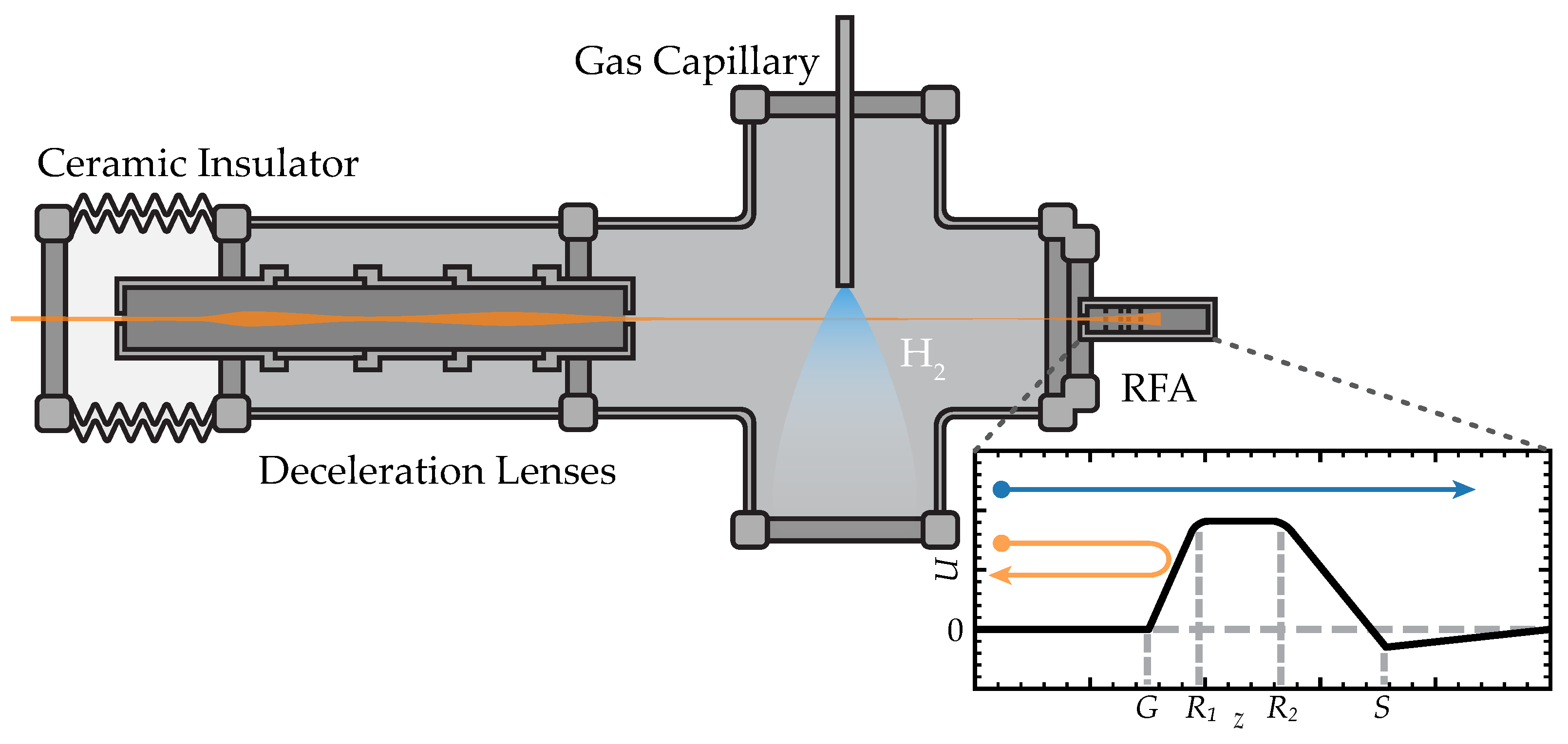
The crossed-beam setup (see Figure 1) used for this work was previously used for measurements of collisions and is described in detail in references [13,17]. To allow measurements to be performed at low kinetic energies, the setup is placed on a high voltage (HV) platform. The energy of the ions inside the collision chamber is thus determined by the potential difference between the ion source and the HV platform. In order to prevent the divergence of the ion beam due to a sudden jump in potential as it enters the collision chamber, a six-element electrostatic deceleration lens is used to contain the ion beam during deceleration. Inside the collision chamber, the ions collide with an effusive gas beam, which is injected through a 100mm long capillary with an inner diameter of 1mm, located 1mm above the center of the ion beam. After collision, the ion beam is collected and analyzed by a Retarding Field Analyzer (RFA). This RFA consists of a Faraday Cup (FC) placed behind a number of electrodes, which, through an applied retarding voltage, produce an electrostatic barrier to the ions; only ions with an energy are able to surpass the barrier and be collected by the FC. Charge-state-resolved ion currents are obtained by varying the retarding potential of the RFA.
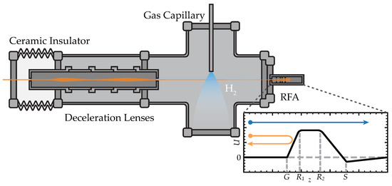
Figure 1.
Schematic overview of the relevant parts of CHEOPS. The crossed-beam setup floats at a high voltage and is insulated from the grounded beamline by a ceramic vacuum break. After deceleration and focusing by the deceleration lenses, the ions (indicated in orange) cross with a target beam after which the beam is collected and its charge state analyzed by a Retarding Field Analyzer (RFA). The inset (bottom right) sketches the potential experienced by ions entering the RFA. Between and , a retarding potential is applied which imposes an energy barrier on ions. Only ions (blue arrow) with energies can overcome the barrier and be collected in the Faraday cup; ions with a lower energy (orange arrow) will be repelled by the barrier.
2.2. Measurement Procedure
The determination of the SEC and BDC cross-sections, and , respectively, requires accurate measurements of the , and ion currents after an initially pure beam has passed through the gas target at multiple densities. The , and charge state distribution can be described by the following system of differential equations:
with being the number of ions of charge state q, being the single and double electron capture cross-sections, respectively, n is the target density and z is the position along the ion beam trajectory. The total trajectory length through the target gas is L. In the single-collision regime, only the left column of the matrix in Equation (4) needs to be considered. The electron capture cross-sections for and ions in columns 2 and 3 contain the effect of double collisions on the charge state distribution. Based on the work by Bijlsma et al. [14], we assume and to be negligibly small compared to the and cross-sections. The cross-section is significant only if the is produced in its metastable term. This is unlikely in BDC by because it would violate the conservation of spin, as will be discussed in the next section. For practical reasons, the total electron capture cross-sections for ions are introduced and the integral target density is taken to be proportional to the pressure (, i.e., . The value of the proportionality constant is obtained from calibration to a collision system with well-established single and double electron capture cross-sections; here, we use the system [18]. With these ingredients, the solutions to the set of differential equations are given by the following:
Equation (5a) allows for the determination of the total electron capture cross-section . To account for the effects of double collisions, we define a ratio f of over ions as given by Equations (5c) and (5b). As the pressures we measure at are reasonably low, this ratio is well described by a Taylor series around :
In the limit of zero density (single collision regime), f is equal to the ratio of the cross-sections for double- and single-electron capture by .
In summary,
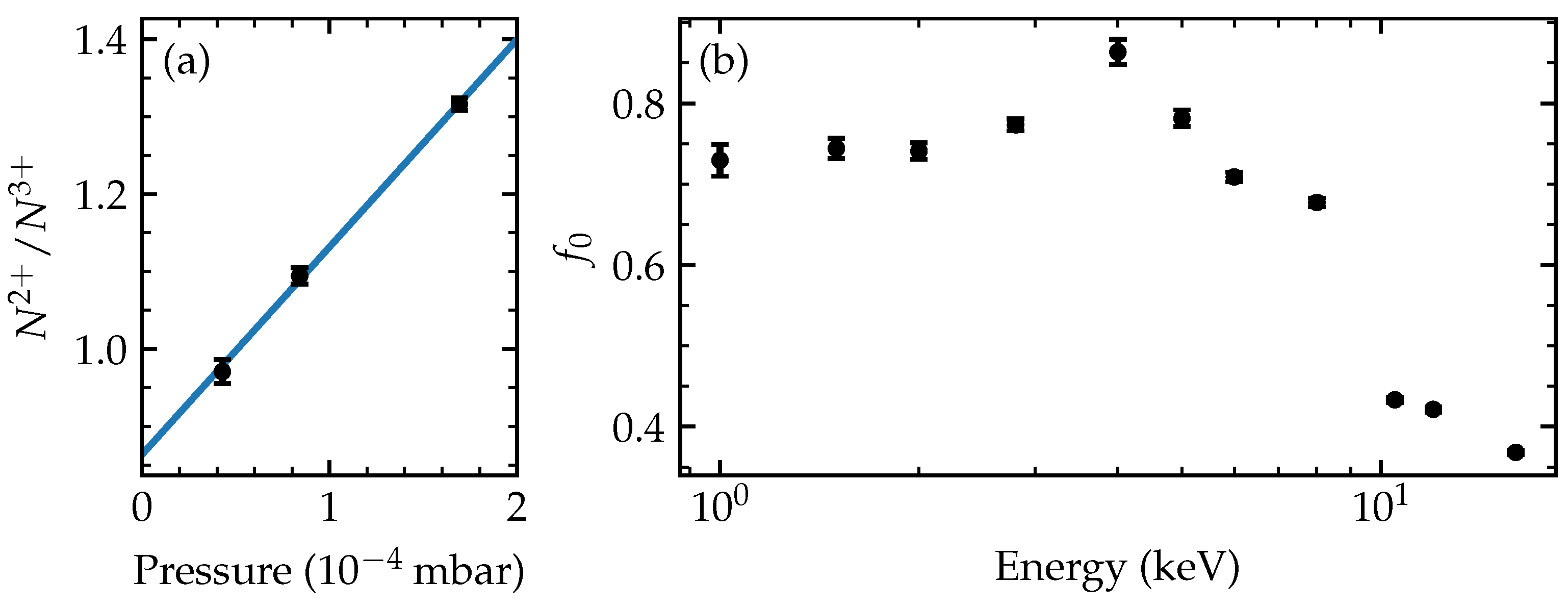
with the value of the ratio f at zero pressure (density). We obtain and from an extrapolated least-squares fit to our measured ratios . An example of this extrapolation, together with all resulting ratios determined over the full range of investigated kinetic energies, are shown in Figure 2.
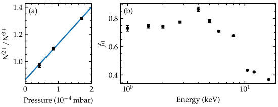
Figure 2.
(a) The ratio f of measured ions to ions generated from a 4 keV ion beam measured at three pressures. The blue line is a least-squares fit to the data. The y-intercept, , is used in Equation (7). (b) The ratio between SEC and BDC cross-sections as a function of energy of the incoming ions. The error bars shown indicate the statistical errors of the measurements.
3. Results and Discussion
The measured cross-sections for colliding with are collected in Figure 3. In the energy range of 1 keV to 8 keV, the SEC and BDC cross-sections are of similar magnitude. Above 8 keV, the cross-sections for SEC and BDC diverge as the SEC cross-sections increase with energy while the BDC cross-sections decrease. The total electron capture cross-section () is basically constant as shown by the dotted grey line. The value of 20 × 10−16 cm2 for the total electron capture cross-section is remarkably low. It is only half of the SEC cross-section for collisions on ; see Figure 3.
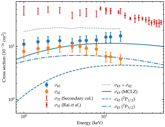
Figure 3.
Experimentally obtained cross-sections for SEC by (blue symbols) and BDC by (orange symbols). The error bars in our and values represent the statistical uncertainty. The 7% systematic uncertainty in our calibration of the proportionality constant is not included. The sum of and is shown by the dashed grey line. The results of multi-channel Landau–Zener calculations of single electron capture () are shown by the solid blue line. The dashed blue lines indicate the individual contributions by the 2 levels to . For a consistency check of our data, indirect cross-sections (red bars), extracted from the double collision contributions to our pressure dependent measurements, (see Figure 2), are compared to the cross-sections measured by Rai et al. [13], which are given by the red dots.
To check the consistency between our present findings for and previous results for , we extracted cross-sections from the double collision contribution to our measurements of the ratio f of 2+ and 3+ ions produced, cf. Equation (6). From that equation, one sees that can be extracted from the slope of f as a function of gas pressure (). The values of () are directly available from the least-squares fits used to extrapolate f to zero pressure; see Figure 2a. From Equation (6), it is derived that
The second correction term between brackets which includes is negligibly small. From Figure 3, one can extract that the ratio is at maximum ∼0.4. The ratio was determined by Rai et al. [13] to be constant over the energy range of 9 keV to 51 keV and to be small, i.e., ∼0.1. At low energies, might change, but even if it would increase threefold when going down to 1 keV, the effect on the cross-sections would be in the order of ~10%. The resultant estimates of the cross-sections are shown in Figure 3 as red uncertainty bars. In the region of overlapping collision energies, we find good agreement between our measurements and those performed by Rai et al. [13], thereby proving the consistency between our present data for and the earlier data set on .
Before continuing the discussion of our data, we would like to point out that the consistency with the earlier results indicates that metastables do not affect our data appreciably. The ion beam may contain a fraction of metastables, having a configuration. The lifetimes of the 1, 3, and 3 40 μs, 1430 s and 171 μs, respectively [19,20]. For 3, no lifetime information is available. The flight time from the source to collision chamber is ~43 μs, meaning that only the 1 and 3 ions experience significant decay (~67% and ~23%). Therefore, although we have a long flight time, it does not exclude the presence of metastables. To assess a presence of metastables, the ECR source has been operated at widely different settings which did not lead to significant changes in the data. This indicates to us that the fraction of metastables is small or has similar cross-sections as the ground state . This conclusion is supported by our determination of the cross-sections, which depend on the ratio of single and double electron capture (). The one electron capture signal is used to put on an absolute scale. All other cross-sections are linked to this calibration. A change in without a change in as a result of a metastable fraction in the beam would result in an overall shift in all cross-sections, reducing the consistency between our and earlier measurements. Therefore, we are convinced that metastables do not affect the presented cross-sections appreciably. However, we cannot exclude the presence of metastables, because their cross-sections might be of similar magnitude to the ones of ground state ions.
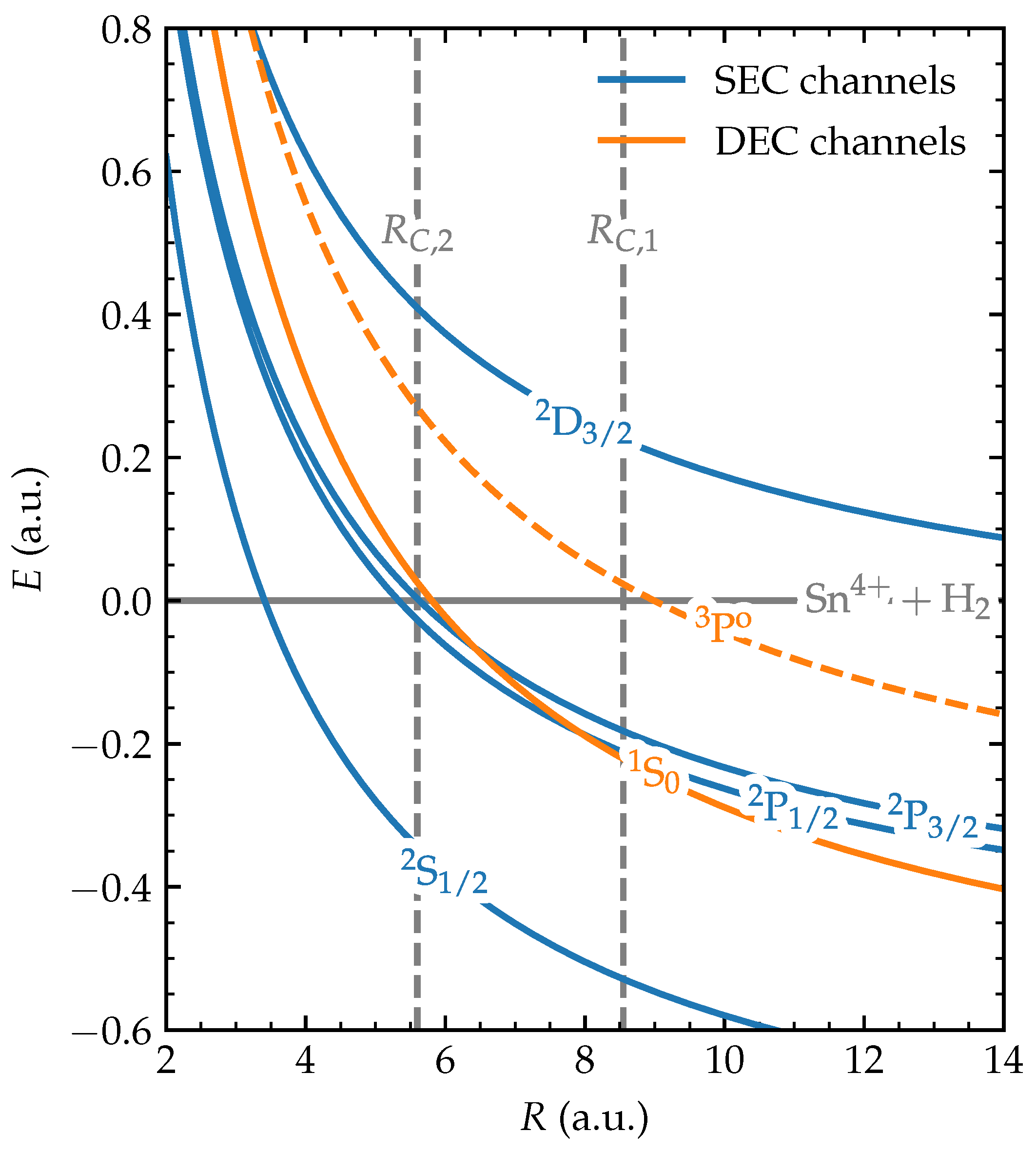
The SEC cross-sections of , being about a factor of three smaller than the ones of , can be explained by considering the potential energy diagram of collisions, which is shown in Figure 4. From the figure it is seen that the curve crossings with the channels will be the most active ones. The crossing of the entrance channel with the channel lies very far out and therefore is crossed adiabatically. The crossings with the levels are located at an internuclear distance of approximately 5.5 This distance of 5.5 should be compared to 8.5 for the effective channel crossing in collisions of ions on [13]. The ratio of the internuclear distances of the crossing points for and squared is in favor of , which is a fair agreement with the measured factor of .
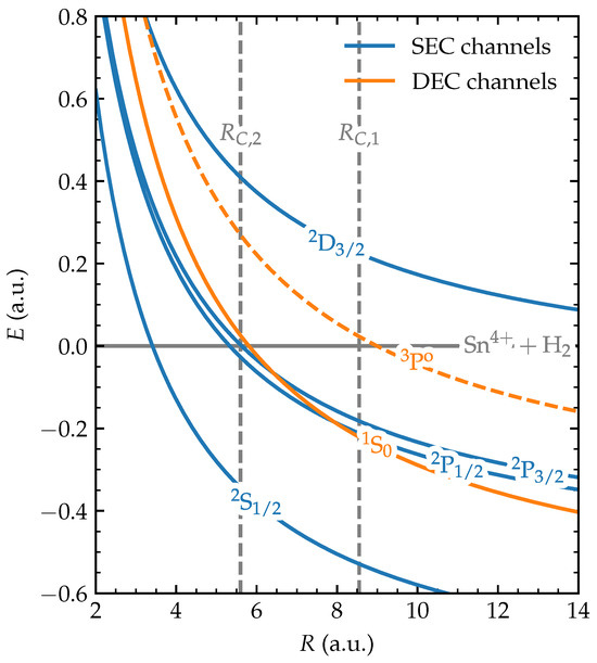
Figure 4.
Potential (Coulomb) energy curves of the relevant (gray), (blue) and (orange) electronic states as functions of the internuclear distance between the ion and the target (dashed line indicates a spin-forbidden final state). The vertical dashed line indicates the over-barrier crossings for single and double electron capture, respectively, used to indicate approximately where resonant capture can start to take place [21]. The term symbols for the ions after separation are indicated in the figure.
To obtain further insight in SEC from by , we have performed multi-channel Landau–Zener (MCLZ) calculations following [22,23]. In the model, the entrance channel and the four single electron capture channels that are shown in Figure 4 have been included. In order to account for the molecular nature of the target, we included the Franck–Condon factor corresponding to a transition to the most likely vibrational state of [24] into the coupling matrix elements , as proposed by Olson and Salop [23]. Instead of the initial prefactor to coupling elements, primarily based on one-electron systems, the empirical prefactor determined by Kimura et al. [22] for collisions on He targets was used. Additionally, the coupling matrix elements are corrected by multiplication with a factor , introduced by Taulbjerg [25] for partially stripped ions to account for the non-degenerate nature of the l states within a specific n shell.
Notwithstanding the approximations inherent to the one-dimensional Landau–Zener model, the calculations agree with the magnitude of the measured single-electron capture cross-sections and indicate that it is indeed the 2 and 2 levels that in between them carry the total SEC cross-section. The corresponding channel-selective and total cross-sections are shown in Figure 3. For energies above approximately 2 keV, the model results are in good agreement with the energy dependence observed in the measurements. Concerning the absolute values, the model falls short by about 30%. Below 2 keV, the difference slowly increases to almost 50% at 1 keV. The same trend, although stronger, has been observed for [14] and was ascribed to the breakdown of the Franck–Condon approximation.
At almost the same internuclear distance as the (2P) crossings, a crossing occurs between the entrance channel and the BDC channel. This level is expected to be the main if not sole contributor to BDC by , as spin conservation (singlet entrance channel) inhibits the population of the next BDC channel which is a triplet ( 3P)). The potential energy diagram in Figure 4 shows that the 1S BDC channel also crosses the 2 levels, which opens the option for electron transfer between SEC and BDC channels on the way-out of the collision. These close crossings raise the question whether double electron capture in this system is facilitated primarily by simultaneous (one-step) or successive (two-step) electron-capture processes [26] and might help to explain the ratio between SEC and BDC by ; see Figure 2b, which maximizes at energies near 4 keV at a value slightly above 0.8.
4. Conclusions
We have measured cross-sections of single and double electron capture by ions from molecular hydrogen in an energy range relevant to the plasma expansion processes in the EUV sources of modern photolithography machines. The cross-sections are extracted from charge-separated ion currents in a crossed-beam experiment of with . Remarkably, the SEC and DEC cross-sections are of similar magnitude and much lower than previously measured cross-sections of SEC by . Our measurements are consistent with earlier work, as is demonstrated by comparing the known cross-sections with those extracted from double collisions in our experiment. The low SEC cross-sections are explained by the absence of potential curve crossings at larger internuclear distances: the first suitable crossings are when the channels cross with the entrance channel at about 5.5 Multi-channel Landau–Zener calculations of are found to be in fair agreement with the measured SEC cross-sections. The BDC capture channel crosses both the entrance channel and SEC channels in the direct vicinity of the crossing of the SEC and entrance channel; this may imply a strong intermixing between SEC and BDC and could therefore require more advanced calculations.
Author Contributions
Conceptualization, R.H.; methodology, E.d.W., L.T. and K.B.; software, E.d.W., L.T. and K.B.; investigation, E.d.W. and L.T.; resources, R.H.; data curation, E.d.W. and L.T.; writing—original draft preparation, E.d.W.; writing—review and editing, E.d.W., L.T., K.B. and R.H.; visualization, E.d.W. and L.T.; supervision, R.H.; project administration, R.H. All authors have read and agreed to the published version of the manuscript.
Funding
This research received no external funding.
Data Availability Statement
The raw data supporting the conclusions of this article will be made available by the authors on request.
Acknowledgments
The experimental work was carried out at the ZERNIKELEIF facility in the Zernike Institute for Advanced Materials of the University of Groningen as part of the research portfolio of the Advanced Research Center for Nanotlithography (ARCNL), a public-private partnership between the University of Amsterdam (UvA), the Vrije Universiteit Amsterdam (VU), the University of Groningen (RuG), the Netherlands organization for Scientific Research (NWO) and the semiconductor equipment manufacturer ASML.
Conflicts of Interest
The authors declare no conflicts of interest.
References
- Janev, R.K.; Winter, H. State-selective electron capture in atom-highly charged ion collisions. Phys. Rep. 1985, 117, 265–387. [Google Scholar] [CrossRef]
- Fritsch, W.; Lin, C.D. The semiclassical close-coupling description of atomic collisions: Recent developments and results. Phys. Rep. 1991, 202, 1–97. [Google Scholar] [CrossRef]
- O’Sullivan, G.; Li, B.; D’Arcy, R.; Dunne, P.; Hayden, P.; Kilbane, D.; McCormack, T.; Ohashi, H.; O’Reilly, F.; Sheridan, P.; et al. Spectroscopy of highly charged ions and its relevance to EUV and soft x-ray source development. J. Phys. B At. Mol. Opt. Phys. 2015, 48, 144025. [Google Scholar] [CrossRef]
- Banine, V.Y.; Koshelev, K.N.; Swinkels, G.H.P.M. Physical processes in EUV sources for microlithography. J. Phys. D Appl. Phys. 2011, 44, 253001. [Google Scholar] [CrossRef]
- Torretti, F.; Sheil, J.; Schupp, R.; Basko, M.M.; Bayraktar, M.; Meijer, R.A.; Witte, S.; Ubachs, W.; Hoekstra, R.; Versolato, O.O.; et al. Prominent radiative contributions from multiply-excited states in laser-produced tin plasma for nanolithography. Nat. Commun. 2020, 11, 2334. [Google Scholar] [CrossRef]
- Fujioka, S.; Nishimura, H.; Nishihara, K.; Murakami, M.; Kang, Y.G.; Gu, Q.; Nagai, K.; Norimatsu, T.; Miyanaga, N.; Izawa, Y.; et al. Properties of ion debris emitted from laser-produced mass-limited tin plasmas for extreme ultraviolet light source applications. Appl. Phys. Lett. 2005, 87, 241503. [Google Scholar] [CrossRef]
- Murakami, M.; Kang, Y.G.; Nishihara, K.; Fujioka, S.; Nishimura, H. Ion energy spectrum of expanding laser-plasma with limited mass. Phys. Plasmas 2005, 12, 062706. [Google Scholar] [CrossRef]
- Doggett, B.; Lunney, J.G. Expansion dynamics of laser produced plasma. J. Appl. Phys. 2011, 109, 093304. [Google Scholar] [CrossRef]
- Nakamura, D.; Tamaru, K.; Hashimoto, Y.; Okada, T.; Tanaka, H.; Takahashi, A. Mitigation of fast ions generated from laser-produced Sn plasma for extreme ultraviolet light source by H2 gas. J. Appl. Phys. 2007, 102, 123310. [Google Scholar] [CrossRef]
- Rai, S.; Bijlsma, K.I.; Poirier, L.; Wit, E.d.; Assink, L.; Lassise, A.; Rabadán, I.; Méndez, L.; Sheil, J.; Versolato, O.O.; et al. Evidence of production of keV Sn+ ions in the H2 buffer gas surrounding an Sn-plasma EUV source. Plasma Sources Sci. Technol. 2023, 32, 035006. [Google Scholar] [CrossRef]
- Bartlett, N.; Herschberg, A.; Crouse, J.; Dallal, T.; Nuttal, J.; Stahl, J.; Braaksma, N.; Ruzic, D. Elastic scattering cross sections and transport of tin ions in extreme ultraviolet lithography sources. Phys. Scr. 2024, 99, 065411. [Google Scholar] [CrossRef]
- Abramenko, D.B.; Spiridonov, M.V.; Krainov, P.V.; Krivtsun, V.M.; Astakhov, D.I.; Medvedev, V.V.; van Kampen, M.; Smeets, D.; Koshelev, K.N. Measurements of hydrogen gas stopping efficiency for tin ions from laser-produced plasma. Appl. Phys. Lett. 2018, 112, 164102. [Google Scholar] [CrossRef]
- Rai, S.; Bijlsma, K.I.; Rabadán, I.; Méndez, L.; Wolff, P.A.J.; Salverda, M.; Versolato, O.O.; Hoekstra, R. Charge exchange in collisions of 1–100-keV Sn3+ ions with H2 and D2. Phys. Rev. A 2022, 106, 012804. [Google Scholar] [CrossRef]
- Bijlsma, K.; Oltra, L.; de Wit, E.; Assink, L.; Rabadán, I.; Méndez, L.; Hoekstra, R. Electron Capture from Molecular Hydrogen by Metastable Sn2+∗ Ions. Atoms 2024, 12, 9. [Google Scholar] [CrossRef]
- Chen, Z.; Wang, X.; Zuo, D.; Wang, J. Investigation of ion characteristics in CO2 laser irradiating preformed tin-droplet plasma. Laser Part. Beams 2016, 34, 552–561. [Google Scholar] [CrossRef]
- Hemminga, D.J.; Poirier, L.; Basko, M.M.; Hoekstra, R.; Ubachs, W.; Versolato, O.O.; Sheil, J. High-energy ions from Nd:YAG laser ablation of tin microdroplets: Comparison between experiment and a single-fluid hydrodynamic model. Plasma Sources Sci. Technol. 2021, 30, 105006. [Google Scholar] [CrossRef]
- Bijlsma, K.; de Wit, E.; Kleinsmit, A.; Lalkens, E.; Assink, L.; Salverda, M.; Oltra, L.; Rabadán, I.; Méndez, L.; Versolato, O.O.; et al. Electron capture in low-energy collisions of Sn3+ ions with H2 and D2. 2024; in preparation. [Google Scholar]
- Machacek, J.R.; Mahapatra, D.P.; Schultz, D.R.; Ralchenko, Y.; Chutjian, A.; Simcic, J.; Mawhorter, R.J. Measurement and calculation of absolute single- and double-charge-exchange cross sections for O6+ ions at 1.17 and 2.33 keV/u impacting He and H2. Phys. Rev. A 2014, 90, 052708. [Google Scholar] [CrossRef]
- Singh, N.; Goyal, A. Energy levels, transition data and collisional excitation cross-section of Sn3+ and Sn4+ ions. J. Electron Spectrosc. Relat. Phenom. 2020, 244, 146982. [Google Scholar] [CrossRef]
- Kramida, A.; Ralchenko, Y. NIST Atomic Spectra Database, NIST Standard Reference Database 78; NIST: Washington, DC, USA, 1999. [CrossRef]
- Niehaus, A. A classical model for multiple-electron capture in slow collisions of highly charged ions with atoms. J. Phys. B At. Mol. Phys. 1986, 19, 2925. [Google Scholar] [CrossRef]
- Kimura, M.; Iwai, T.; Kaneko, Y.; Kobayashi, N.; Matsumoto, A.; Ohtani, S.; Okuno, K.; Takagi, S.; Tawara, H.; Tsurubuchi, S. Landau-Zener Model Calculations of One-Electron Capture from He Atoms by Highly Stripped Ions at Low Energies. J. Phys. Soc. Jpn. 1984, 53, 2224–2232. [Google Scholar] [CrossRef]
- Olson, R.E.; Salop, A. Electron transfer between multicharged ions and neutral species. Phys. Rev. A 1976, 14, 579–585. [Google Scholar] [CrossRef]
- Wacks, M.E. Franck-Condon factors for the ionization of H2, HD, and D2. J. Res. Natl. Bur. Stand. Sect. A Phys. Chem. 1964, 68A, 631. [Google Scholar] [CrossRef]
- Taulbjerg, K. Reaction windows for electron capture by highly charged ions. J. Phys. B At. Mol. Phys. 1986, 19, L367. [Google Scholar] [CrossRef]
- Barat, M.; Roncin, P. Multiple electron capture by highly charged ions at keV energies. J. Phys. B At. Mol. Opt. Phys. 1992, 25, 2205. [Google Scholar] [CrossRef]

Disclaimer/Publisher’s Note: The statements, opinions and data contained in all publications are solely those of the individual author(s) and contributor(s) and not of MDPI and/or the editor(s). MDPI and/or the editor(s) disclaim responsibility for any injury to people or property resulting from any ideas, methods, instructions or products referred to in the content. |
© 2025 by the authors. Licensee MDPI, Basel, Switzerland. This article is an open access article distributed under the terms and conditions of the Creative Commons Attribution (CC BY) license (https://creativecommons.org/licenses/by/4.0/).