Abstract
A conceptual design study is presented for a hemispherical, two-chamber water Cherenkov detector instrumented with bladder-embedded light traps. The detector consists of a rigid aluminium vessel enclosing a water volume that is divided into an outer, optically black chamber and a inner, reflective chamber lined by a flexible bladder. Arrays of light-trap modules, based on plastic scintillators with wavelength-shifting elements and thin silicon photomultipliers, are integrated into the bladder and selected inner surfaces. This geometry is intended to enhance muon tagging, increase acceptance for inclined air showers, and enable improved discrimination between electromagnetic and hadronic components. The study describes the mechanical and optical layout of the detector, the baseline aluminium housing, and the use of 3D-printed hexagonal prototypes to validate integration of the bladder and readout electronics. A first-order structural assessment based on thin-shell and plate theory is presented, indicating large safety margins for the hemispherical shells and identifying the flat base as the mechanically most loaded component. While GEANT4 simulations for detector response to extensive air showers in the atmosphere and performance measurements are left to future work, the present study establishes a mechanically validated, costed baseline design and outlines the steps needed to assess its impact in air-shower arrays.
1. Introduction
Some sources, including pulsars, supernova remnants, active galactic nuclei (AGNs) and gamma-ray bursts, are capable of producing particles and photons with extreme energies, ranging from hundreds of GeV to PeV and beyond. When these very energetic particles enter the Earth’s atmosphere and interact with atmospheric nuclei, they generate cascades of secondary particles, known extensive air showers (EAS).
The energy spectrum of cosmic rays (CRs) follows a power law: lower energy particles are much more common, whereas higher-energy particles become increasingly rare. At around a few PeV ( eV), this spectrum steepens, forming a feature known as the “knee”. Above the knee, the flux of cosmic rays drops off more sharply, which suggests that many typical Galactic accelerators are reaching their maximum acceleration energy. Below the knee, cosmic rays are generally thought to originate within our Galaxy, but it is still not possible to uniquely identify and confirm which class of sources dominates their production. Candidate accelerators that can push particles up to PeV energies or beyond are referred to as PeVatrons. Finding and confirming such PeVatrons in the Milky Way is an active goal of current high-energy gamma-ray observatories [1,2,3].
Before 2021, a central question in high-energy astroparticle physics was whether the Milky Way contains any genuine Galactic PeVatrons at all. Reviews such as [3] still described the existence and identity of such extreme accelerators as an open problem. Ground-based gamma-ray observatories, including High-Altitude Water Cherenkov Observatory (HAWC), had identified several very-high-energy gamma-ray sources and classified some of them as “PeVatron candidates,” but their measured spectra typically extended only to energies of order ∼100 TeV [4]. This was highly suggestive of particle acceleration approaching the PeV scale, yet it did not constitute definitive proof that the parent particles were being accelerated to petaelectronvolt energies.
This situation changed qualitatively after 2021, when Large High Altitude Air Shower Observatory (LHAASO) reported multiple Galactic sources emitting gamma rays above 100 TeV, including photons with energies up to about 1.4 PeV, detected with very high statistical significance [5]. These observations provided direct evidence that PeV-scale acceleration is occurring within the Milky Way and shifted the focus of the field. The key questions are no longer centred on whether Galactic PeVatrons exist, but rather on the nature of the specific accelerators involved, on how these environments confine and eventually release PeV particles into the interstellar medium, and on whether the observed gamma-ray emission is predominantly hadronic, arising from interactions of PeV protons and nuclei, or leptonic, produced by extremely energetic electrons. Addressing these issues requires combining spectral and morphological gamma-ray measurements with multiwavelength and, where possible, multimessenger observations, in order to disentangle competing scenarios and to build a consistent physical picture of Galactic PeVatron sources.
Therefore, and to address the questions about the nature of Galactic PeVatrons and the mechanisms by which they accelerate and release PeV particles, one requires precise measurements of gamma rays and cosmic rays over many decades, extending from the GeV range to well beyond 100 TeV. Space-based detectors are extremely effective up to approximately the GeV–TeV domain, but the flux of both gamma rays and cosmic rays falls rapidly with increasing energy, which makes it increasingly difficult to acquire sufficient statistics with satellite instruments at very high energies [6]. In the very-high-energy and ultra-high-energy regime, observational strategies therefore change: instead of detecting the primary particles directly in space, one exploits the Earth’s atmosphere as a giant calorimeter. A primary gamma ray or cosmic ray entering the atmosphere interacts with air nuclei and initiates an extensive air shower containing thousands of secondary electrons, positrons, photons, hadrons and muons.
These particle cascades are observed indirectly using two complementary classes of ground-based instruments: imaging atmospheric Cherenkov telescopes (IACTs) and extensive air shower (EAS) arrays, including arrays of water Cherenkov detectors. As the air shower front propagates downward at nearly the speed of light, it gives rise to two principal observables. First, the relativistic charged particles in the shower produce a short, nanosecond-scale flash of Cherenkov light in the atmosphere, which is imaged by IACTs. Second, a fraction of the secondary electrons, positrons, photons (via pair production) and especially muons survive to ground level, where EAS arrays sample their spatial and temporal distributions. In addition, heavy cosmic-ray nuclei radiate a small amount of “direct” Cherenkov light high in the atmosphere before their first interaction. This light is more narrowly beamed than the Cherenkov emission from the subsequent air shower, because it is produced at higher altitude where the refractive index of air is closer to unity, and because lower-energy shower particles suffer stronger deflections that broaden the light pool. A telescope located at an appropriate impact distance, of the order of one hundred meters from the primary trajectory, can, in principle, detect both the direct and shower Cherenkov components. From the recorded Cherenkov images and the sampled secondary particles, one reconstructs the arrival direction of the primary (astrometry), its energy (spectroscopy), and, to some extent, its nature. This facilitates the distinction between gamma rays from hadronic cosmic rays and, in favorable cases, inferring the mass of charged primaries.
At the core of these techniques lies the physics of Cherenkov radiation itself. When an electrically charged particle traverses a dielectric medium with a speed exceeding the phase velocity of light in that medium, it induces a polarization of the material that relaxes in the form of coherent electromagnetic radiation. The basic condition for Cherenkov emission is that the particle velocity v is larger than the speed of light in the medium,
where is the particle velocity in units of the speed of light in vacuum and n is the refractive index of the medium. Under these conditions, the radiation is emitted as a characteristic cone around the particle trajectory, forming a “shock” wavefront analogous to the sonic boom produced by an object moving faster than the speed of sound in air. The opening angle of this cone, the Cherenkov angle , is given by
so that, for a medium with known dielectric properties, a measurement of provides a direct handle on the particle speed.
The intensity and spectral distribution of Cherenkov light are described by the Frank–Tamm formula, which gives the number of photons emitted per unit path length and per unit wavelength,
where is the fine-structure constant, z is the charge of the particle in units of the elementary charge, and is the wavelength-dependent refractive index. In the context of atmospheric showers, these properties are exploited on a macroscopic scale: the angular and spatial distribution, intensity and timing of the Cherenkov light, together with the pattern of secondary particles at ground level, encode the development of the cascade and thereby the properties of the primary particle that initiated it.
In practical terms, modern imaging atmospheric Cherenkov telescopes (IACTs) implement this technique by using large optical reflectors to collect the brief Cherenkov flash from the air shower and focus it onto fast photosensors in a focal-plane camera. These cameras are typically based on two main sensor technologies. Photomultiplier tubes (PMTs) are vacuum-tube devices in which an incident photon strikes a photocathode, liberating an electron that is then multiplied through a cascade of dynodes to produce a large, fast electrical pulse. Although PMTs offer very high gain and excellent timing performance, they are relatively fragile and require high operating voltages. Silicon photomultipliers (SiPMs), by contrast, are solid-state devices composed of many tiny avalanche photodiodes operated in Geiger mode and connected in parallel, each capable of firing on a single photon; they are compact, operate at low voltage and are insensitive to magnetic fields, but they exhibit higher dark noise and can saturate at high light levels. The focal-plane camera records a two-dimensional image of Cherenkov light from the shower in the atmosphere, and the morphology of this image encodes key information: its orientation on the sky provides the incoming direction of the primary particle, its length and width correlate with the energy and stage of shower development, and deviations from the expected “gamma-like” shape allow discrimination between gamma-ray-induced showers and the more irregular hadronic showers initiated by charged cosmic rays [7]. Arrays of IACTs, such as H.E.S.S., MAGIC, VERITAS and Cherenkov Telescope Array (CTA), observe the same shower from multiple viewing angles, which substantially improves angular resolution, energy reconstruction and background rejection, and thereby enables precision studies of very-high-energy gamma-ray sources and potential Galactic PeVatrons.
Imaging atmospheric Cherenkov telescopes offer several key strengths that have made them the leading instruments for very-high-energy gamma-ray astronomy. Their stereoscopic imaging capability yields very good angular resolution, down to approximately 0.1 deg for bright sources, enabling detailed studies of source morphology and the separation of nearby emission regions. Over their core energy range, from roughly 100 GeV up to a few tens of TeV, IACTs also achieve good energy resolution, which allows precise reconstruction of gamma-ray spectra and the identification of spectral features such as cutoffs or breaks. As pointed instruments with deep exposure on selected regions, they are particularly powerful for targeted observations of known sources, where long integrations can deliver high signal-to-noise measurements and spatially resolved spectroscopy. These strengths come with important limitations. The duty cycle is intrinsically restricted, because observations require dark, clear, and largely moonless nights; as a result, the effective uptime is typically only of the order 10–15% [7]. In addition, the instantaneous field of view is relatively narrow, with only a few degrees across. This, in turn, constrains the ability to survey large fractions of the sky efficiently. Taken together, these factors limit the capability of IACTs to perform unbiased, continuous all-sky monitoring and to capture unexpected transient events without prior pointing.
These limitations motivate a complementary approach based on wide-field extensive air shower (EAS) arrays. Instead of imaging Cherenkov light with optical telescopes, such arrays deploy many particle detectors over a large area at ground level and continuously sample the secondary particles from air showers that arrive from a broad range of directions. Extensive air shower arrays measure, in particular, the spatial distribution and timing of secondary particles at the surface, including the relative arrival times of the shower front at many detector stations, which constrains key properties of the cascade. By fitting the observed timing pattern across the array, the arrival direction of the primary particle can be reconstructed with good precision. In contrast to IACTs, these instruments operate continuously, day and night, and can operate in a wide range of weather and moonlight conditions, achieving an effective duty cycle close to 100%. In addition, EAS arrays observe a large fraction of the overhead sky simultaneously, with an instantaneous field of view of order steradians, which makes them well suited for unbiased sky surveys and for catching rare or unexpected transient events. Prominent examples of such facilities include Milagro and its successor HAWC in Mexico, as well as LHAASO in China.
A particularly successful implementation of the EAS technique is based on water Cherenkov detection, which is employed in several modern wide-field arrays. In this approach, secondary shower particles at ground level—electrons, positrons, photons that convert to pairs, and, in particular, muons—enter large water tanks distributed over the array. If a charged particle traverses the water with a speed exceeding the phase velocity of light in the medium, it emits Cherenkov radiation, which propagates as a cone of optical photons. Photomultiplier tubes installed at the bottom of each tank record the resulting signals, providing both the pulse amplitude, which is related to the energy deposited in the detector, and the precise signal timing, which constrains the geometry and curvature of the shower front. An array comprising many such tanks samples the lateral distribution of the shower at ground level, enabling reconstruction of the shower size and direction. Since muons are more penetrating than the purely electromagnetic component, their signals can be distinguished and used as a powerful discriminator against hadronic background, thereby enhancing the sensitivity of water Cherenkov EAS arrays to gamma-ray–induced showers.
In recent decades, both imaging atmospheric Cherenkov telescopes and extensive air shower arrays have delivered major advances in ground-based high-energy astroparticle physics. They have enabled the detection and spectral characterisation of a large population of TeV gamma-ray sources, including pulsar wind nebulae, supernova remnants and active galactic nuclei [7,8]. These instruments have also made it possible to map diffuse gamma-ray emission along the Galactic plane, which traces the spatial distribution of cosmic rays and constrains their propagation in the interstellar medium [9]. In the context of PeVatrons, ground-based observatories have identified promising candidates through multi–100 TeV and, more recently, PeV gamma-ray emission, implying that particles are indeed being accelerated within the Milky Way up to PeV-scale energies [1]. In parallel, continuous time-domain monitoring of the TeV sky by wide-field instruments such as HAWC has provided sensitivity to flares and transient phenomena that pointed IACTs may miss because of their limited duty cycle and narrow field of view [2].
Despite these achievements, several fundamental questions remain. A primary issue is the origin of the highest-energy cosmic rays: although there are plausible candidate source classes, we still lack a definitive census of which objects dominate the observed ultra-high-energy cosmic-ray flux [3]. It also remains unclear which physical mechanisms can efficiently accelerate particles to PeV energies, since diffusive shock acceleration in its simplest form may not always suffice; additional ingredients such as strong turbulence or extreme electromagnetic fields may be required. Other active lines of research focus on how cosmic rays escape from their sources and propagate through the Galaxy [9], and on the reliability of hadronic interaction models at extreme energies. Current models, extrapolated beyond LHC energies, do not always reproduce the measured muon content of extensive air showers, leading to a discrepancy between observed and simulated muon yields that is often referred to as the “muon puzzle” [10,11]. This deviation may indicate that there are still gaps in our understanding of hadronic physics or shower development in this energy regime.
To address some of these issues and mitigate the limitations of the present global observatory network, including sky coverage asymmetry, transient response and background rejection at extreme energies, recent years have seen a rise in proposed new collaborations one of which is Southern Wide-Field Gamma Ray Observatory (SWGO) [2]. SWGO is a planned wide-field, high-duty-cycle gamma-ray observatory in the Southern Hemisphere proposed in Chile at approximately 4770 m altitude. SWGO will deploy a large array of WCD units, with a dense inner core and a more extended outer array [2]. Since most existing gamma-ray observatories are located in the Northern Hemisphere, SWGO is designed to provide continuous monitoring of the Southern sky, including the Galactic Centre and the inner southern Galactic plane, with sensitivity from the GeV to the PeV range. In combination with the Northern facilities (such as LHAASO and HAWC), SWGO will enable nearly continuous, all-sky coverage at very high energies.
SWGO will consist of a dense inner core and an outer array of more sparsely spaced detector units. While the inner array is designed to provide precise sampling of the air-shower front near the core and to deliver high-quality event reconstruction at intermediate energies, the outer array is optimised to (1) detect muons and other particles at large distances from the shower core, (2) constrain the shower footprint and core position for the highest-energy events, (3) improve the estimation of the primary particle energy, and (4) enhance gamma–hadron discrimination through muon tagging in the outer regions of the shower.
However, SWGO’s science goals place stringent requirements on detector unit design, especially in the outer array, where a large number of robust, cost-effective stations must provide efficient muon tagging and good sensitivity to particles far from the shower core. In this context, SWGO will employ water Cherenkov detectors (WCDs), widely used in astroparticle physics and cosmic-ray experiments to detect extensive air showers and to tag penetrating muons. Their large active volumes, robustness, and relatively low cost make them attractive for large-area arrays. However, conventional WCD designs are typically based on simple cylindrical or box-like geometries, with a modest number of photodetectors and limited flexibility in separating different shower components or in performing efficient muon tagging.
To address this limited flexibility of conventional WCD geometries for shower-component separation and efficient muon tagging, we propose a hemispherical, optically segmented WCD. The active volume is divided into an outer and an inner chamber with distinct optical treatments, with the outer chamber incorporating an instrumented bladder. While motivated by the requirements of large-area EAS arrays like SWGO, the design can be adopted in future arrays or upgrades where stringent muon-tagging performance is required.
Within this design, the outer chamber is optically black and instrumented to measure prompt, predominantly direct light, whereas the inner chamber is lined with a reflective surface to enhance the collection of muon-induced Cherenkov photons. Light-trap modules—based on plastic scintillators with wavelength-shifting elements and silicon photomultipliers (SiPMs)—are embedded in the bladder that is confined to the outer chamber, while additional modules are mounted along the inner surfaces, providing distributed instrumentation in both volumes. The bladder is intended to be fabricated from PVC or a PVC-like material, similar to that used in HAWC [12]. Mechanical support is provided by a rigid aluminium shell with a top hatch, allowing straightforward insertion and removal of the bladder assembly.
The goals of this paper are to (i) present the conceptual design of the hemispherical, two-chamber water Cherenkov detector, including its mechanical configuration and optical layout; (ii) describe the aluminium housing and the integration of bladder-embedded light traps, supported by 3D-printed hexagonal prototypes for assembly and electronics validation; and (iii) discuss the expected advantages and potential drawbacks of the hemispherical two-chamber architecture in the context of extensive air-shower arrays. To provide a reasonable basis for this detector concept, the paper also (iv) includes an initial cost estimate and a first-order structural evaluation based on thin-shell and plate theory. At this stage, the work is a design and feasibility study: no detailed simulation results or experimental performance measurements are reported. Prototype detector units will be used in a second phase to validate the concept with cosmic-ray data and to benchmark future optical and array-level simulations.
2. Materials and Methods
2.1. Detector Concept and Geometry
A target sensitivity comparable to that envisioned for next-generation wide-field EAS gamma-ray observatories (e.g., SWGO) in the – range implies instrumenting a multi-square-kilometre area with a relatively low fill factor of order 1–4, such that individual detector units are spatially isolated. At these energies, the rate of air showers induced by hadronic cosmic rays exceeds the rate of photon-induced showers in a typical field of view by roughly three to five orders of magnitude, while the absolute gamma-ray signal rate remains low [13,14,15]. As a consequence, the array must achieve very efficient rejection of the hadronic background, with an effective gamma/hadron separation power corresponding to background suppression at the level of ∼–, depending on the energy and the analysis cuts. In wide field-of-view water Cherenkov arrays, this separation critically relies on an accurate determination of the muon content of each event. Namely, hadronic showers typically contain abundant high-energy muons, whereas photon-induced cascades are strongly muon-poor. Therefore, precise muon counting over large lateral distances is essential as it allows for even proton-induced showers with unusually low muon content to be distinguished from gamma-induced events.
Even though muon tagging is most effectively achieved with underground muon detectors, such installations are invasive to the terrain and entail substantial civil-engineering costs. A more economical alternative is to exploit a large depth of water inside the detector itself, so that only muon-induced signals are produced at the deepest layers. However, a detector unit based solely on a deep vertical tank must still provide an efficient veto against particles entering through the lateral surfaces. Since constructing very thick lateral shielding around a tall cylindrical tank is impractical, a hemispherical tank geometry is proposed instead, as shown in Figure 1.
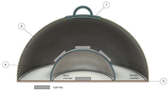
Figure 1.
Hemispherical two-chamber detector. The active volume is divided into an outer and a inner hemispherical chamber, the former of which is lined by a flexible bladder. The outer chamber is internally blackened to suppress reflections, while the inner chamber has a reflective inner surface so that only the Cherenkov light from traversing muons is recorded there. Light-trap sensors are embedded in the bladder, along the inner surface of the outer chamber, and within the inner chamber. All signal and steering cables are routed through the bladder and extracted to the outside via a top hatch. The complete bladder–sensor assembly is inserted through a top hatch into a rigid hemispherical aluminium shell that defines the detector geometry.
With that being said, the proposed detector unit consists of a hemispherical water tank divided into an outer and an inner chamber, the former of which is lined by a flexible bladder. The bladder is a thin, watertight liner that spans the equatorial plane of the hemisphere and hosts an array of embedded light-trap modules. The outer chamber is designed to be optically black, with internal surfaces coated or lined with highly absorbing material to suppress reflections. The inner chamber is lined with reflective material to increase the effective light collection from Cherenkov photons produced by traversing muons.
The mechanical enclosure is a rigid aluminium shell with a hemispherical geometry. A circular hatch is located at the top of the hemisphere and provides access for inserting and removing the instrumented bladder and associated cabling. During assembly, the bladder, including all light traps, sensors, and steering cables, is pre-integrated as a single module. This module is then inserted through the top hatch into the hemispherical shell. Cabling is routed outwards through the hatch and is connected to the external readout electronics.
Both chambers are equipped with light-trap sensors. In the nominal configuration, the outer chamber hosts multiple light traps arranged approximately along a spherical surface, facilitating wide angular coverage and sensitivity to a range of incidence angles. The reflective inner chamber, together with the water volume beneath the bladder, enhances the collection of photons associated with muons traversing the tank, while the outer chamber provides complementary information useful for event classification and background rejection.
2.2. Light-Trap Modules
The light traps being developed at the University of Padova are based on wavelength-shifting (WLS) large-area plastic elements (disks, bars) (Eljen Technology, Sweetwater, TX, USA) or WLS fibres (Kuraray, Tokyo, Japan) coupled to silicon photomultipliers (SiPMs) [16]. These share a polymer base with refractive index and are doped with fluorescent molecules that absorb UV/blue Cherenkov photons and re-emit them isotropically at longer wavelengths. A large fraction of this re-emitted light is confined inside the WLS volume by total internal reflection and guided towards its edges or fibre ends. The trapping efficiency depends on the geometry (disk or tube) and on the surrounding medium (air or water), with typical values of 10–80%. In practice, the WLS function can be realised either by bulk doping of the plastic or by applying a WLS paint or layer on the entrance surface, so that the primary Cherenkov light is shifted before being transported within the bulk material and directed towards the readout [16].
The wavelength-shifted photons trapped inside the WLS components are collected at the borders by SiPMs. In the present laboratory setup, Hamamatsu MPPCs (S14160/S14161) with an active area of are used. They provide single-photon sensitivity and a photon-detection efficiency of about 30–50% in the 300–600 nm range, well-matched to the emission spectra of the WLS materials [16]. Prototype light-trap units, combining WLS elements and SiPM readout, have already been assembled and tested, and an example of a planar WLS light-trap prototype and its envisaged integration in a hemispherical detector is shown in Figure 2.
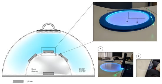
Figure 2.
Conceptual implementation and laboratory demonstration of bladder-embedded WLS light traps. Left: cross-sectional sketch of the hemispherical two-chamber detector showing the arrangement of light-trap modules (grey) in the outer “electron” and inner “muon” chamber. Right: photographs of a planar WLS light-trap prototype developed at the University of Padova, consisting of a wavelength-shifting plastic disk with a SiPM mounted on its edge and illuminated by a pulsed UV LED. The upper-right image shows the full disk under illumination, illustrating the trapping and guiding of light along the rim. Panels A and B highlight details of the light injection and the guided emission along the disk edge, respectively.
In the hemispherical detector concept, these light-trap modules are distributed over the bladder and the inner chamber. Their modularity and relatively low cost allow for a high channel density without significantly increasing the mechanical complexity of the tank. Detailed engineering design and performance optimization of the light-trap modules are beyond the scope of this work and are therefore only discussed at a conceptual level. For more detail, see [16].
2.3. Aluminium Housing Shell
For large-scale deployment, the baseline solution is a custom aluminium shell that houses the water volume, bladder, and light traps. Aluminium is chosen for its mechanical robustness, resistance to environmental stress and good machinability. The shell forms a hemispherical tank with a wall thickness chosen to withstand hydrostatic pressure and environmental loads such as snow and wind. External stiffening ribs or a supporting frame can be added where needed to ensure structural integrity under site-specific conditions.
The inner surface of the shell is prepared differently in the two chambers. In the outer chamber, a black, highly absorbing coating or a liner is applied to minimize reflections and define a well-controlled optical environment for the light traps. In the inner chamber, a reflective liner or foil is installed to enhance the probability that Cherenkov photons reach a light-trap module after multiple reflections. The interface between the two chambers is defined by the bladder itself, which also serves as the support structure for the embedded sensors.
The top hatch is dimensioned to allow the pre-assembled bladder and sensor package to be lowered into the tank. Mechanical attachment points on the inner wall support the bladder and keep it in the desired equatorial position. Cable inputs near the hatch provide a watertight path for power, bias lines, and signal cables to the outside. The shell is designed to be compatible with standard lifting and transport equipment, facilitating handling during installation and maintenance.
The aluminium housing is divided into four main components: a top access hatch, the outer hemispherical shell, the structural base plate, and the inner hemispherical shell that defines the inner chamber. The pre-assembled bladder and sensors are mounted inside this structure. An exploded view of the detector unit, together with the parts list and nominal masses, is shown in Figure 3.
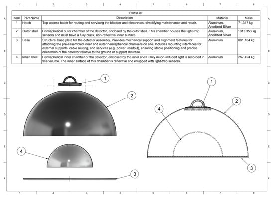
Figure 3.
Exploded view of the hemispherical detector unit and associated parts list. The assembly is composed of (1) a top access hatch for routing and servicing the bladder and electronics, (2) the outer aluminium shell forming the upper, optically black chamber, (3) a structural base plate that supports the detector on site and provides interfaces for services and cabling, and (4) the inner aluminium shell forming the lower, reflective chamber where muon-induced light is recorded.
The overall dimensions of the detector unit are constrained by the desired water volume, transport limits, and the spacing foreseen in the outer array. A compact hemispherical geometry with an external diameter of approximately 3.5 m was adopted for the baseline design. Figure 4 summarizes the key dimensions and mechanical features, including the curvature radii of the shells, the base thickness, and the diameter and inclination of the access hatch.
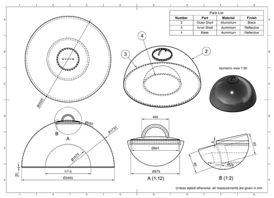
Figure 4.
Dimensioned mechanical drawing of the hemispherical water Cherenkov detector unit. The top view, sectional views and isometric projection show the outer shell, the inner shell defining the inner chamber, and the flat base plate. The drawing specifies the main diameters, radii and heights used in the baseline design, as well as the geometry of the access hatch.
2.4. Structural Modelling and Loading Assumptions
A screening-level structural model of the hemispherical vessel was implemented in Python 3.12.12 to obtain first-order estimates of stress magnitudes and stability margins. The outer and inner chambers are idealised as thin hemispherical shells of radii and , respectively, each with wall thickness . Both shells are assumed to share a common equatorial support and to interface with a flat circular base plate of radius . The annular volume between the shells is assumed to be completely filled with water, with a free surface located at the crown of the outer dome.
The water pressure is modelled as hydrostatic with gauge pressure
where , , and is the depth below the free surface. The free surface is taken to be at atmospheric pressure, so represents a pressure difference relative to atmosphere. The applied pressure differentials on the shells are defined as follows. The outer shell experiences internal water pressure with atmospheric pressure externally, so the net pressure differential acting on the shell is (acting outward). The inner shell is assumed to enclose an atmospheric cavity, while its exterior is exposed to the water pressure ; therefore, the net pressure differential acting on the inner shell is (acting inward). The inner surfaces of both shells are discretised in polar coordinates, and is evaluated at each surface point. The self-weight of the aluminium shells is neglected in this first-order model.
To obtain an order-of-magnitude estimate of stress levels associated with the local pressure, a spherical thin-wall scaling relation is used,
where R is the shell radius and t is the wall thickness. This expression is exact for a complete spherical shell under uniform pressure; in the present configuration (hemispherical caps with an equatorial boundary and non-uniform hydrostatic loading), it is used only as a conservative scaling estimate of membrane stress magnitude. Bending effects, boundary-condition effects at the equator, and local stress concentrations (e.g., hatch cut-outs, welds, and supports) are neglected, and the resulting shell stress maps should therefore be interpreted as screening metrics rather than design stresses [17].
The flat base plate is idealised as a clamped circular plate of radius and thickness . For the plate bending check, the plate is subjected to a uniform pressure load equal to the hydrostatic gauge pressure at the bottom,
Under classical small-deflection plate theory, the maximum bending stress at the plate centre for a clamped, uniformly loaded circular plate is [17]
where is Poisson’s ratio. This provides a conservative first-order estimate of the bending stress associated with pressure loading, noting that large-deflection effects are not captured by the small-deflection theory and that the effective boundary condition in service may differ from the fully clamped idealisation. The foundation bearing problem, including contact pressure transmitted to soil or a slab due to the total weight of water and structure, constitutes a separate load case and is not combined with the internal hydrostatic pressure loading used for the plate bending estimate.
The susceptibility of the inner shell to elastic buckling under external pressure is assessed using the classical critical pressure for a perfect thin spherical shell [18]
where E is Young’s modulus and is Poisson’s ratio. Typical aluminium properties and are adopted. Since real shells are imperfection-sensitive, and the present geometry is a hemispherical cap with an equatorial boundary and a non-uniform hydrostatic pressure field, is treated as an upper bound. A conservative knockdown factor is applied to define an effective screening value,
with the understanding that certification-level buckling assessment requires dedicated analysis incorporating boundary conditions, geometric imperfections, and the actual pressure distribution. All calculations were taken with double precision and visualised as pressure and stress maps over the shell surfaces, together with representative bending stress measures for the base plate. These calculations are intended to provide relative load/stress scaling and preliminary risk identification, and are not a substitute for design-code verification or certification-level finite-element analysis incorporating boundary conditions, geometric imperfections, and nonlinear response.
2.5. Prototype Development with 3D-Printed Hexagonal Panels
While the aluminium shell is the baseline solution for operational detector units, early prototypes will be constructed using 3D-printed panels to validate the mechanical interfaces and the integration of the bladder and electronics, as shown in Figure 5. Moreover, such prototyping will also make it possible to assess the feasibility of manufacturing detector housing by additive methods, in case aluminium prices continue to rise and alternative, more cost-efficient fabrication routes become attractive.
Figure 5.
Technical drawing of the -diameter 3D-printed hemispherical prototype. The lower view shows the cross-section of the outer shell, inner shell and base plate, including the circular hatch and handle at the top. The upper right inset gives the geometry of a single hexagonal panel (side length , thickness ) with its interlocking features, while the isometric view illustrates the assembled shell covered by hexagonal tiles.
In this prototyping approach, the hemispherical shell (outer diameter ∼) is realised as a scaled-down version of the full-size detector, chosen for practicality and available laboratory space. The geometry is approximated by a tessellation of regular hexagonal tiles mounted on a circular base plate. Each tile is a regular hexagon with a side length of and a thickness of . Shallow tongue-and-groove features along the edges allow neighbouring hexagons to interlock like puzzle pieces, providing self-alignment during assembly and increasing the stiffness of the resulting shell. The detailed geometry of these connection links is shown in Figure 6.
Figure 6.
Assembly concept for the 3D-printed hexagonal panels. The upper inset shows a patch of PLA Strongman hexagons interlocked like puzzle pieces, which are subsequently bonded to the circular PERSPEX base plate of diameter. The detailed view A (1:1) and the side and plan drawings specify the panel dimensions (side length , thickness ) and the tongue-and-groove connection links between neighbouring tiles.
The tiles are printed by fused-filament fabrication on a Raise3D Pro3 printer, using PLA Strongman filament, a high-strength PLA-based material chosen for its combination of good dimensional stability, enhanced toughness compared to standard PLA, and adequate thermal resistance for the expected outdoor temperature range. The hexagonal hemispherical array is bonded to a circular base disk made of PERSPEX 30/962 (cast PMMA) with a diameter of and a thickness of . Mechanical and watertight joints are achieved using a two-component structural adhesive formulated for plastics, in combination with a fast-curing auxiliary adhesive for local tacking during assembly. This combination provides good adhesion to both PLA and PMMA, sufficient peel and shear strength for handling and filling tests, and convenient working times for on-bench assembly.
The 3D-printed housing is not proposed as a direct replacement for the aluminium shell in a full-scale observatory. Instead, it serves as a modular and cost-effective platform to test key aspects of the concept: the placement and fixation of light traps on a curved surface, the routing and strain relief of cables, the behaviour of the bladder under repeated filling and emptying cycles, and the basic performance and stability of the readout chain. The modular nature of the hexagonal panels enables rapid design iterations, replacement of individual tiles, and systematic studies of different assembly strategies and tolerances. Laboratory equipment such as a digital oscilloscope, a coincidence unit, and standard soldering and hand tools were procured to support the assembly and characterisation of these prototypes. With that being said, the baseline solution for large-scale deployment remains the aluminium shell, but experience gained with the hexagonal 3D-printed prototypes will inform its optimisation and provide input on whether partially or fully additively manufactured housings could become a viable option for specific applications or cost scenarios in future arrays.
At the time of submission, the prototype is in mechanical fabrication and component-level verification. Therefore, system-level measurements (e.g., photon-detection efficiency, sealing performance, and cable-routing stability) are not yet available and will be reported separately.
3. Results
3.1. Design Validation and Structural Assessment
3.1.1. Static Strength and Stability Under Hydrostatic Loading
Using the structural model and assumptions described in Section 2.4, the hydrostatic gauge pressure field and associated screening-level stress measures were evaluated for the outer and inner hemispherical shells. With the free surface at the crown of the outer dome, the maximum hydrostatic pressure occurs at the equator and is
The self-weight of the aluminium shells was neglected in this first-order assessment. Shell stresses were estimated using thin-sphere pressure scaling as an order-of-magnitude membrane stress measure (rather than an exact solution for a hemispherical cap under non-uniform hydrostatic loading). For the outer shell, this gives a maximum stress scale of ; for the inner shell () under the same external hydrostatic field, . Adopting a conservative yield strength of for structural aluminium alloys, the corresponding screening safety factors against yielding are (outer shell) and (inner shell). Figure 7a,b show the resulting stress maps, which primarily reflect the hydrostatic pressure variation with depth.
Figure 7.
Approximate structural response of the hemispherical detector unit under hydrostatic loading. The outer and inner chambers are modelled as thin hemispherical shells of radii and , both with wall thickness , resting on a flat circular base of radius . Panel (a): screening-level stress scale on the outer shell based on the thin-sphere scaling using the hydrostatic gauge pressure field. Panel (b): corresponding stress scale for the inner shell under external hydrostatic pressure. Panel (c): base plate idealised as a clamped circular plate under uniform pressure , annotated with the centre bending-stress estimate from classical small-deflection plate theory. Panel (d): hydrostatic gauge pressure distribution, with at the equator setting the relevant load scale for the assessment.
For the flat base plate, the bending check was treated as a separate internal-pressure load case. The plate was idealised as a clamped circular plate of radius and thickness under a uniform pressure load equal to the hydrostatic gauge pressure at the base,
Using the classical small-deflection expression for a clamped, uniformly loaded circular plate (Section 2.4) with yields a maximum bending stress at the plate centre of (about ), corresponding to a screening safety factor of relative to . Figure 7c illustrates this base plate idealisation. This estimate neglects geometric nonlinearity and the supporting effect of the soil or slab; therefore, it should be interpreted as an indicative stress scale for a conservative boundary condition and a simplified load path. The foundation bearing problem, i.e., the contact pressure due to the total weight of water and structure, is treated as a distinct load case and is not combined with the internal hydrostatic pressure bending estimate.
The elastic buckling safety of the inner shell under external pressure was assessed using the classical spherical-shell buckling expression (Section 2.4). For , , and , the classical critical pressure for a perfect shell is (∼). Spherical shells are highly imperfection sensitive, and experimentally observed buckling pressures can be substantially lower than the classical prediction [18,19]. Applying a conservative knock-down factor gives an effective screening value . Since the maximum hydrostatic pressure in operation is , as seen in Figure 7d, the ratio remains well below unity. Elastic buckling of the inner shell under external pressure is, therefore, not a limiting factor at the screening level; instead, local strength (openings, welds), boundary/support details, fabrication tolerances, and long-term environmental actions are expected to govern any detailed mechanical optimisation.
The stress values reported above are intended as screening-level stress scales derived from simplified analytical idealisations rather than detailed predictions. The spherical thin-wall relation is used here only to provide an order-of-magnitude membrane-stress scale under the non-uniform hydrostatic field; it does not capture local bending, equatorial boundary-condition effects, or stress concentrations at welds, penetrations, and the hatch interface. Likewise, the base-plate check employs a clamped circular-plate idealisation under a uniform pressure load and neglects any supporting effect of soil-to-slab contact and potential load redistribution, so it should be interpreted as an indicative bending-stress scale for the assumed load path and boundary condition. The elastic buckling check similarly uses the classical critical pressure for a perfect spherical shell with a conservative knockdown factor and therefore represents a screening metric rather than a certification-level prediction. Self-weight and coupled load combinations are neglected in this first-order model. Accordingly, these estimates should be interpreted as preliminary sizing guidance. Subsequent wall-thickness optimisation will be performed using coupled load combinations and higher-fidelity finite-element models (e.g., hydrostatics plus self-weight, foundation/contact effects, wind and seismic actions, and local joint/penetration sub-models) to ensure engineering practicality and robust margins.
3.1.2. Mass Budget and Structure-to-Water Ratio
The CAD model of the reference detector geometry yields a total aluminium mass of ≃ per unit, corresponding to approximately for the outer shell, for the base, for the inner shell and for the top hatch, as seen in Figure 3. For an outer radius of , the hemispherical water volume enclosed by the vessel is of the order
i.e., about of water. The resulting structure-to-water mass ratio is therefore ∼. This ratio is higher than in existing m-class WCD tanks built from plastic or thin steel shells [20,21,22], but remains compatible with a robust aluminium design aimed at long-term operation in harsh environments. Combined with the safety factors derived above, this suggests that there is room for further optimisation of shell and base thicknesses, for example through finite-element analysis including realistic support, wind and seismic load combinations, to reduce structural mass while retaining similar safety margins.
3.2. Cost Estimate
An order-of-magnitude cost estimate was carried out for the proposed hemispherical detector unit, assuming an outer array of 6000 WCDs. The main cost drivers are the aluminium mechanical structure (outer and inner shells, base and hatch), the light-trap and SiPM instrumentation, and the local electronics and services required for autonomous operation of each station. Central infrastructure (buildings, long-distance networking, and central DAQ) is not included in this estimate and would need to be treated separately at the array level.
For the mechanical structure, the CAD model of the 3.5 m-diameter tank with a uniform wall thickness of 20 mm yields a total aluminium mass of approximately per detector unit. As a rough order-of-magnitude estimate, the raw metal cost can be derived from recent aluminium prices. Global commodity prices for primary aluminium over the 2023–2025 period are at the level of ∼ [23,24], while supplier quotes for 6xxx/7xxx-series sheet and plate in multi-ton lots typically fall in the range of ∼2– [25]. Adopting a representative value of for large-scale procurement leads to a raw aluminium cost of ∼ per tank. Applying a multiplicative factor of 1.4 to account for forming, welding, machining, quality assurance, and industrial overheads then results in a structural cost of about per unit. This is broadly consistent with, though somewhat higher than, effective tank costs inferred for 3.6 m-class WCDs in existing and proposed arrays, and reflects the deliberately conservative wall thickness adopted in the present design [20].
The remaining cost elements include the light-trap and SiPM assemblies, front-end and local DAQ electronics, power and communications, water and internal materials, and site preparation and installation. These contributions are benchmarked against published estimates for small WCD stations in SWGO-like designs and scaled to the specific instrumentation envisaged here. A target value of is assumed for the light-trap and SiPM package per detector, with a further for local front-end electronics. Power, communications and timing are budgeted at per unit, while water, internal fixtures and minimal site works contribute at the few-hundred-dollar level. The resulting breakdown, summarised in Table 1, yields a total indicative cost of ∼ per detector, corresponding to ∼ for 6000 units, as seen in Figure 1.

Table 1.
Illustrative cost model for a hemispherical two-chamber water Cherenkov detector (WCD) unit with an aluminium shell and bladder-embedded light traps. Costs are given per detector and for an outer array of 6000 WCDs, in 2022–2025 USD-equivalent. The cost of the aluminium structure is derived from the CAD mass of ∼ t per unit and current market prices for 6000-series aluminium plate, scaled by a factor of 1.4 to account for forming, welding, machining and industrial overheads. Values are indicative order-of-magnitude estimates assuming production of >6000 units and do not include central infrastructure (buildings, long-distance networking, central DAQ).
The values outlined in Figure 1 should be regarded as design targets rather than firm quotations. The dominant structural cost is strongly dependent on the final wall thickness and fabrication approach, and is anticipated to fall to a fraction of the current estimate once the mechanical design is optimised. Likewise, the cost of the light-trap modules and electronics will benefit from economies of scale and technological progress in SiPM-based readout. A more precise budget will require detailed engineering studies and industrial tenders, but the present estimate indicates that the hemispherical concept is compatible with the cost scale of other planned large-area WCD arrays.
4. Discussion
4.1. Conceptual Performance Advantages
The hemispherical two-chamber configuration is motivated by the central role of muon information in wide field-of-view gamma-ray observatories. At TeV–PeV energies, gamma/hadron separation increasingly hinges on reliable identification and counting of muons in the shower footprint [26,27,28]. In the proposed design, muons that traverse the tank laterally or at large zenith angles do not simply contribute to a diffuse, undifferentiated signal. Instead, they are expected to leave characteristic patterns in the lower, reflective chamber, where Cherenkov light from penetrating tracks is efficiently collected by the embedded light traps. This should enhance muon tagging in the outer array region, where the EM component is already diluted and muon information is most valuable for background rejection.
The separation into an outer optically black chamber and an inner reflective chamber is consistent with dual-layer WCD concepts explored for SWGO-like EAS arrays, where a dedicated muon-sensitive compartment is paired with an EM-sensitive volume to improve gamma/hadron discrimination and core reconstruction [29,30]. In addition, the use of many small light-trap modules distributed over the inner surfaces effectively increases the granularity of the optical readout. Studies with conventional WCDs have shown that even modest arrays of PMTs can provide strong muon-identification power when spatial and temporal signal patterns are exploited with modern analysis or machine-learning techniques [26]. A densely instrumented two-chamber tank is therefore expected to carry rich information in both light yield and time structure, which can, in principle, be used to refine event classification once detailed simulations are available.
From the point of view of air-shower array design, the proposed unit is intended primarily for use in the sparse outer region, where detectors sample the tail of the particle footprint at large core distances. In current and planned arrays, this outer region is crucial for constraining the shower geometry, improving energy reconstruction and tagging muon-rich events [28,30]. The combination of a lower volume optimised for penetrating particles and an outer volume sensitive to the more diffuse EM component is particularly suited to this role. By comparing the relative responses of the two chambers as a function of core distance and zenith angle, it may become possible to extract additional composition-sensitive observables and to improve the reconstruction of highly inclined and off-axis showers, in analogy to the multi-component strategies adopted in LHAASO and AugerPrime [28,31].
The mechanical aspects of the design also offer practical advantages. The hemispherical aluminium shell is structurally simple and, in the present implementation, operates with very large static safety margins: the thin-shell analysis indicates safety factors against yielding of order a few hundred for the domes, while even the flat base remains within acceptable limits under conservative loading assumptions. This level of over-design is compatible with long-term operation under the environmental conditions foreseen for high-altitude sites and leaves room for later optimisation of wall thicknesses and mass. At the same time, the flexible bladder with embedded light traps is mechanically decoupled from the shell, so that it can be handled as a single instrumented insert.
Finally, the separation between a long-lived structural vessel and a replaceable bladder assembly has potential benefits over the lifetime of the observatory. Experience from existing facilities such as the Pierre Auger Observatory shows that large arrays evolve over decades and may undergo substantial upgrades to their surface detectors and electronics [22,31]. In the present concept, the aluminium tank can be installed and verified on site independently of the photosensors. Bladder modules with different light-trap geometries, sensor generations or readout schemes could, in principle, be prepared off site and exchanged with limited impact on civil infrastructure. This modularity is intended to simplify maintenance and upgrades, and to keep the detector technology adaptable as improved optical and electronic components become available.
4.2. Reliability and Maintainability
The proposed hemispherical detector unit does require a larger water volume per tank than some conventional WCD designs. This is an inherent consequence of the two-chamber geometry and the relatively large active depth. However, the enhanced acceptance and muon-tagging capability offered by the dual-volume configuration may allow a given array-level sensitivity to be reached with fewer detector units. In that case, the higher per-tank water requirement could be offset, at least in part, by a reduced number of tanks and associated infrastructure. A quantitative optimisation of the array layout, including realistic trigger and reconstruction performance, will be needed to assess this trade-off.
In terms of reliability, the closed aluminium vessel is conceived as a long-lived structural component. The hemispherical geometry and continuous wall thickness provide a simple and robust load path for environmental stresses, while the structural assessment in Section 3.1.1 indicates large safety margins against yielding and buckling under static loads. The sealed shell, with a single top hatch and a limited number of feedthroughs for cabling and services, is expected to show good resistance to weathering, thermal cycling and mechanical impacts, and to reduce the risk of leaks or external contamination. Once installed on a suitable foundation, the outer housing should not require routine intervention beyond periodic visual inspections and checks of the hatch seal and external hardware.
The internal bladder and light-trap assembly are treated as a replaceable subsystem. All optical and electronic components associated with the water volume are integrated into the bladder or its immediate fixtures, so that they can be removed and reinserted as a single module through the top hatch. In the event of a significant failure or degradation of the internal instrumentation, the water can be drained, the hatch opened and the bladder extracted for repair or replacement without disturbing the main mechanical structure. This modular approach is intended to simplify major interventions compared to designs in which sensors are permanently bonded to the tank walls.
Although access to the interior of a fully assembled aluminium shell is necessarily more constrained than in an open-frame prototype, the use of a standardised access path through the top hatch and a self-contained bladder module keeps maintenance operations conceptually simple. Bladders prepared and tested off site could, in principle, be swapped in the field with limited detector downtime. This separation between a durable structural envelope and a serviceable inner assembly is aimed at supporting multi-decade operation while retaining flexibility to upgrade the photosensors and readout technology over the lifetime of the observatory.
4.3. Path to Full-Scale Implementation
A realistic assessment of the potential of the hemispherical detector concept ultimately requires a plan for producing and deploying a large outer array. Beyond the single-unit design and cost estimates presented here, a full implementation would need an integrated construction and logistics strategy covering the aluminium shells, bladders, light-trap instrumentation and on-site civil works. The procurement and shipping steps are conceptually similar to those of existing WCD-based observatories, but the specific geometry and mass of the hemispherical tanks imply different handling and packaging constraints. Standardised shell designs with identical hatches, lifting points and external interfaces are intended to simplify these aspects and to enable serial production.
On site, the main civil tasks are the preparation of foundations or support pads, the provision of access roads and laydown areas, and the availability of suitable lifting equipment. One advantage of the compact hemispherical geometry is that each unit can be treated as a self-contained mechanical object which can be placed on a prepared pad and aligned without the need for extensive in situ assembly. The sensitive bladder and light-trap modules can be transported separately, installed only after the shells have been positioned and surveyed, and removed again if major servicing is required. This separation between structural and instrumental components is intended to reduce the risk of damage during construction and to decouple the schedule of civil works from that of detector integration.
For the outer array, the detector units are foreseen to be deployed on a regular or quasi-regular grid over a large area, with the spacing optimised for high-energy shower sampling, muon tagging and overall cost. The low profile and robust aluminium housing are designed with remote, high-altitude environments in mind, where wind, snow and temperature variations are significant and access for heavy machinery may be limited. An illustrative rendering of a possible deployment scenario, with detector units installed on a plateau, is shown in Figure 8. In such a configuration, the standardised shells and top hatches provide a common interface for power, communications and slow-control services, facilitating the design of a repeatable “unit cell” for the outer array.
Figure 8.
Illustrative rendering of several hemispherical detector units deployed on a high-altitude plateau, representing a possible configuration of the outer array. The compact, low-profile aluminium shells are designed for simple placement on prepared foundations, with the instrumented bladders inserted from the top hatch after installation and connected to power and readout services via standardised external interfaces.
In practice, a full-scale implementation would proceed through an intermediate engineering array. It is advisable that only a limited number of clusters of hemispherical units be deployed initially, at a site representative of the intended environmental conditions. This engineering array would serve as a testbed for validating the mechanical robustness of the shells and bases, the long-term stability of the bladder and light traps, the behaviour of seals and coatings under UV exposure and thermal cycling, and the integration of the readout and data acquisition systems with the broader observatory infrastructure. Experience gained in this phase would feed back into refinements of the mechanical design, installation procedures and quality-control protocols, and would provide the empirical underpinning for the cost and schedule models used in planning a full outer array.
4.4. Limitations and Future Work
The present study is intentionally restricted to a conceptual level. The detector layout, mechanical envelope and cost model for the hemispherical two-chamber unit have been specified, and a first-order structural assessment has been carried out, but no detailed optical simulations or experimental performance measurements are yet available. As a result, the expected gains in muon-tagging efficiency, electromagnetic–hadronic discrimination, and effective area for inclined events remain qualitative. Likewise, the structural analysis is based on thin-shell and plate theory under static hydrostatic loading and does not yet include detailed finite-element modelling of welds, supports, wind and seismic loads, or fabrication tolerances.
A first line of future work will, therefore, focus on dedicated optical simulations. A full Monte Carlo chain, coupling air-shower simulations (e.g., based on CORSIKA) to detector-level optical transport (e.g., using Geant4), is needed to quantify the light-collection efficiency, time distributions and spatial response of both chambers for different primary types, energies and core distances. Such simulations will be used to optimise the number, placement and orientation of light traps, the choice of reflective and absorbing coatings, and the readout thresholds and trigger logic. They will also allow a direct comparison of the hemispherical two-chamber unit with more conventional single-volume WCD designs under realistic operating conditions.
In parallel, a staged prototype programme is required to validate the concept experimentally. At an early stage, 3D-printed hexagonal shells and small-scale housings can be used to test the integration of the bladder, light traps and readout electronics, and to measure basic quantities such as gain, timing resolution and cross-talk using cosmic-ray muons and calibration light sources. Subsequent prototypes based on an aluminium shell will allow the mechanical aspects of the design to be exercised, including filling and draining procedures, thermal cycling, and the behaviour of the bladder and seals under realistic environmental conditions. These tests should be accompanied by more detailed mechanical analyses, for example finite-element studies of the base support, hatch region and weld seams. Namely, the next stage of work will transition from screening-level sizing to engineering verification and qualification. This will include (i) higher-fidelity finite-element simulations incorporating site- and deployment-dependent load cases, including wind and seismic spectra, anchoring/foundation boundary conditions, and relevant load combinations, and (ii) local sub-modelling of stress concentrations at welds, penetrations, and the top-hatch interface to establish robust design margins and guide optimisation of mass-critical components, including the flat base and hatch region. Moreover, all mechanical components will be tested at component level prior to system integration, after which integrated structural tests and accelerated environmental aging campaigns (e.g., UV exposure and temperature cycling) will be conducted to quantify long-term performance of the aluminium shell and the bladder or seal materials. These activities are outside the scope of the present conceptual study and will be reported in dedicated follow-up work.
Finally, the detector concept needs to be embedded in full array-level simulations. By placing the hemispherical units in realistic outer-array layouts and coupling them to a reconstruction and analysis chain, one can quantify their impact on key performance metrics such as gamma/hadron separation, energy and core resolution, and anisotropy sensitivity, as well as on the overall cost and logistical complexity of the installation. This will make it possible to assess whether the additional structural and water volume per tank is compensated, at the array level, by improved physics performance or a reduced number of required detector sites. The outcome of these studies will guide further optimisation of the design and clarify the conditions under which the proposed detector is a competitive option for next-generation wide field-of-view gamma-ray observatories.
5. Conclusions
This work has presented a conceptual design for a hemispherical water Cherenkov detector unit in which the active volume is divided into an outer, optically black chamber and an inner reflective chamber by a flexible bladder instrumented with light-trap modules. The detector is housed in a rigid aluminium shell with a top hatch, allowing the pre-assembled bladder and embedded sensors to be inserted and removed as a single unit. Light traps based on plastic scintillator elements with wavelength-shifting components and thin SiPM readout provide a dense and modular optical instrumentation of the interior surfaces.
The two-chamber geometry, combined with the spatially distributed light traps, is intended to address specific needs of next-generation air-shower arrays, in particular in their outer regions. By separating the outer volume optimised for sampling the electromagnetic component from the inner volume optimised for penetrating muons, the design aims to enhance muon tagging, improve gamma/hadron discrimination and increase the acceptance for inclined and off-axis events relative to more conventional single-volume WCDs. A first-order structural assessment based on thin-shell and plate theory indicates that the hemispherical aluminium vessel operates with very large safety margins against yielding and buckling, while identifying the flat base as the mechanically most stressed component under static loading. The CAD-based mass budget and cost model suggest that, for large production runs, the per-unit cost is dominated by the light-trap instrumentation rather than by the aluminium shell, and that there is scope for further optimisation of wall thickness and mass.
At this stage, the technological readiness of the concept corresponds to an initial design definition: detailed three-dimensional models and technical drawings have been produced, and a staged prototype programme is planned, starting from 3D-printed shells and progressing to full aluminium units. No detailed optical simulations or experimental performance measurements are yet available, so the anticipated gains in physics performance remain qualitative. Future work will, therefore, include a dedicated simulation chain coupling air-shower and detector-level optics, construction and testing of prototype units with cosmic-ray muons, and studies of array-level layouts that incorporate the hemispherical units in an outer array. If these steps confirm that the expected improvements in muon tagging and shower reconstruction can be realised at competitive cost and with manageable logistics, the proposed detector could provide a robust and versatile building block for the outer components of future wide field-of-view gamma-ray and cosmic-ray observatories.
Author Contributions
Conceptualization, M.D. and J.I.; methodology, J.I., M.D. and M.M.; software, J.I.; validation, M.M.; formal analysis, J.I.; investigation, J.I.; resources, M.M.; data curation, J.I. and M.M.; writing—original draft preparation, J.I.; writing—review and editing, J.I., M.D. and M.M.; visualization, J.I.; supervision, M.M.; project administration, M.M.; funding acquisition, J.I. and M.M. All authors have read and agreed to the published version of the manuscript.
Funding
This work was supported by the Croatian Science Foundation (HrZZ) under project “Very-high-energy Gamma Ray Astronomy in the Multi-messenger Era” (ASTRO-GAMMA, no. IP-2022-10-4595) awarded to M.M., and by the Prometej grant of the University of Rijeka Foundation (Zaklada Sveučilišta u Rijeci) awarded to J.I.
Data Availability Statement
The Python script used to run the simulations for design validation and structural assessment can be obtained from the corresponding author upon reasonable request.
Acknowledgments
During the preparation of this manuscript, ChatGPT (GPT-5.2, OpenAI) was used to assist with language editing, rephrasing and formatting of text and figure captions. The scientific content, analysis and conclusions were developed by the authors, who have reviewed and edited all AI-assisted text and take full responsibility for the final manuscript. All CAD models and renders were prepared with Autodesk Fusion 360 (v2605.1.39, x86_64, 2025), with some undergoing additional post-processing using Canva (v1.119.0.0). All structural modeling analyses were carried out in Python (v3.12.12).
Conflicts of Interest
The authors declare no conflicts of interest.
References
- Mohanty, P.K. Cosmic ray sources and detectors. Eur. Phys. J. Spec. Top. 2025, 234, 5009–5019. [Google Scholar] [CrossRef]
- SWGO Collaboration; Abreu, P.; Alfaro, R.; Alfonso, A.; Andrade, M.; Angüner, E.O.; Anita-Rangel, E.A.; Aquines-Gutiérrez, O.; Arcaro, C.; Arceo, R.; et al. Science Prospects for the Southern Wide-field Gamma-ray Observatory: SWGO. A. Jard. 2025, 17. [Google Scholar] [CrossRef]
- Alves Batista, R.; Biteau, J.; Bustamante, M.; Dolag, K.; Engel, R.; Fang, K.; Kampert, K.H.; Kostunin, D.; Mostafa, M.; Murase, K.; et al. Open Questions in Cosmic-Ray Research at Ultrahigh Energies. Front. Astron. Space Sci. 2019, 6, 448617. [Google Scholar] [CrossRef]
- Albert, A.; Alfaro, R.; Alvarez, C.; Camacho, J.R.A.; Arteaga-Velázquez, J.C.; Arunbabu, K.P.; Rojas, D.A.; Solares, H.A.A.; Baghmanyan, V.; Belmont-Moreno, E.; et al. HAWC J2227 + 610 and Its Association with G106.3 + 2.7, a New Potential Galactic PeVatron. Astrophys. J. Lett. 2020, 896, L29. [Google Scholar] [CrossRef]
- Cao, Z.; Aharonian, F.A.; An, Q.; Axikegu; Bai, L.X.; Bai, Y.X.; Bao, Y.W.; Bastieri, D.; Bi, X.J.; Bi, Y.J.; et al. Ultrahigh-energy photons up to 1.4 petaelectronvolts from 12 γ-ray Galactic sources. Nature 2021, 594, 33–36. [Google Scholar] [CrossRef]
- Baldini, L. Space-Based Cosmic-Ray and Gamma-Ray Detectors: A Review. arXiv 2014, arXiv:1407.7631. [Google Scholar] [CrossRef]
- Aharonian, F.; Buckley, J.; Kifune, T.; Sinnis, G. High energy astrophysics with ground-based gamma ray detectors. Rep. Prog. Phys. 2008, 71, 096901. [Google Scholar] [CrossRef]
- The CTA Consortium. Science with the Cherenkov Telescope Array; World Scientific: Singapore, 2019. [Google Scholar] [CrossRef]
- Tibaldo, L.; Gaggero, D.; Martin, P. Gamma Rays as Probes of Cosmic-Ray Propagation and Interactions in Galaxies. Universe 2021, 7, 141. [Google Scholar] [CrossRef]
- Anchordoqui, L.A.; Canal, C.G.; Kling, F.; Sciutto, S.J.; Soriano, J.F. An explanation of the muon puzzle of ultrahigh-energy cosmic rays and the role of the Forward Physics Facility for model improvement. J. High Energy Astrophys. 2022, 34, 19–32. [Google Scholar] [CrossRef]
- Shepetov, A.L.; Shaulov, S.B.; Likiy, O.I.; Ryabov, V.A.; Sadykov, T.K.; Saduev, N.O.; Zhukov, V.V. The rise of muon content in extensive air showers after the 3 PeV knee of the primary cosmic ray spectrum according to data of the Tien Shan mountain installation. Astropart. Phys. 2021, 133, 102642. [Google Scholar] [CrossRef]
- Mostaf, M.; Longo, M.; Salesa Greus, F.; Warner, D. A Water Cherenkov Detector prototype for the HAWC Gamma-Ray Observatory. In Proceedings of the 32nd International Cosmic Ray Conference, Beijing, China, 11–18 August 2011. [Google Scholar] [CrossRef]
- La Parola, V.; Cusumano, G.; Lombardi, S.; Compagnino, A.A.; La Barbera, A.; Tutone, A.; Pagliaro, A. Machine Learning-Enhanced Discrimination of Gamma-Ray and Hadron Events Using Temporal Features: An ASTRI Mini-Array Analysis. Appl. Sci. 2025, 15, 3879. [Google Scholar] [CrossRef]
- Sitarek, J.; Sobczyńska, D.; Adamczyk, K.; Szanecki, M.; Bernlöhr, K. Estimation of the height of the first interaction in gamma-ray showers observed by Cherenkov telescopes. Astropart. Phys. 2018, 103, 108–114. [Google Scholar] [CrossRef]
- Unbehaun, T.; Lang, R.G.; Deka Baruah, A.; Bedur Ramesh, P.; Celic, J.; Mohrmann, L.; Steinmassl, S.; Olivera-Nieto, L.; Hinton, J.; Funk, S. Improvements to monoscopic analysis for imaging atmospheric Cherenkov telescopes: Application to H.E.S.S. Astron. Astrophys. 2025, 694, A162. [Google Scholar] [CrossRef]
- Pihet, M.; Mariotti, M.; Arcaro, C. Wavelength-shifting light traps for SWGO and other applications. PoS 2023, ICRC2023, 926. [Google Scholar] [CrossRef]
- Timoshenko, S.; Woinowsky-Krieger, S. Theory of Plates and Shells, 2nd ed.; McGraw–Hill: New York, NY, USA, 1987; pp. 79–98. [Google Scholar]
- Hutchinson, J.W. Buckling of spherical shells revisited. Proc. R. Soc. A Math. Phys. Eng. Sci. 2016, 472, 20160577. [Google Scholar] [CrossRef]
- Baumgarten, L.; Kierfeld, J. Shallow shell theory of the buckling energy barrier: From the Pogorelov state to softening and imperfection sensitivity close to the buckling pressure. Phys. Rev. E 2019, 99, 022803. [Google Scholar] [CrossRef]
- Bellido, J.; Schneider, M.; Abreu, P.; Albert, A.; Alfaro, R.; Alfonso, A.; Álvarez, C.; An, Q.; Angüner, E.O.; Arcaro, C.; et al. Manufacture Details of a SWGO Double-Layer Tank Design—Water Cherenkov Detector Prototype. Proc. Sci. 2024, 444, 803. [Google Scholar] [CrossRef]
- Allekotte, I.; Barbosa, A.F.; Bauleo, P.; Bonifazi, C.; Civit, B.; Escobar, C.O.; García, B.; Guedes, G.; Gómez Berisso, M.; Harton, J.L.; et al. The surface detector system of the Pierre Auger Observatory. Nucl. Instruments Methods Phys. Res. Sect. A Accel. Spectrometers Detect. Assoc. Equip. 2008, 586, 409–420. [Google Scholar] [CrossRef]
- The Pierre Auger Collaboration. The Pierre Auger Cosmic Ray Observatory. Nucl. Instruments Methods Phys. Res. Sect. A Accel. Spectrometers Detect. Assoc. Equip. 2015, 798, 172–213. [CrossRef]
- YCharts. Aluminum Price (Monthly)—Historical Data & Trends; YCharts: Chicago, IL, USA, 2025. [Google Scholar]
- The London Metal Exchange. LME Aluminium|London Metal Exchange; The London Metal Exchange: London, UK, 2025. [Google Scholar]
- ReportLinker. European Unwrought Aluminium Price Per Unit by Country; ReportLinker: Lyon, France, 2021. [Google Scholar]
- Conceição, R.; González, B.S.; Guillén, A.; Pimenta, M.; Tomé, B. Muon identification in a compact single-layered water Cherenkov detector and gamma/hadron discrimination using machine learning techniques. Eur. Phys. J. C 2021, 81, 542. [Google Scholar] [CrossRef]
- Conceição, R.; Costa, P.J.; Gibilisco, L.; Pimenta, M.; Tomé, B. The gamma/hadron discriminator LCm in realistic air shower array experiments. Eur. Phys. J. C 2023, 83, 932. [Google Scholar] [CrossRef]
- Celli, S.; Peron, G. Detection prospects of very and ultra high-energy gamma rays from extended sources with ASTRI, CTA, and LHAASO. Astron. Astrophys. 2024, 689, A258. [Google Scholar] [CrossRef]
- Kunwar, S.; Goksu, H.; Hinton, J.; Schoorlemmer, H.; Smith, A.; Hofmann, W.; Werner, F. A double-layered Water Cherenkov Detector array for Gamma-ray astronomy. Nucl. Instruments Methods Phys. Res. Sect. A Accel. Spectrometers, Detect. Assoc. Equip. 2023, 1050, 168138. [Google Scholar] [CrossRef]
- Chiavassa, A. [SWGO Collaboration]. SWGO: A wide-field of view gamma-ray observatory in the southern hemisphere. J. Instrum. 2024, 19, C02065. [Google Scholar] [CrossRef]
- Anastasi, G.A. AugerPrime: The Pierre Auger Observatory upgrade. Nucl. Instrum. Meth. A 2022, 1044. [Google Scholar] [CrossRef]


Disclaimer/Publisher’s Note: The statements, opinions and data contained in all publications are solely those of the individual author(s) and contributor(s) and not of MDPI and/or the editor(s). MDPI and/or the editor(s) disclaim responsibility for any injury to people or property resulting from any ideas, methods, instructions or products referred to in the content. |
© 2026 by the authors. Licensee MDPI, Basel, Switzerland. This article is an open access article distributed under the terms and conditions of the Creative Commons Attribution (CC BY) license.