Abstract
Dual-band RF amplifiers play increasingly important roles in next-generation mobile communication systems including 5G, and the out-of-band intermodulation products are often not negligible since they generate interference to adjacent channels. In this article, following our previous modeling of cross-modulation for amplified dual-band signals, an analytical expression of out-of-band intermodulation for dual-band orthogonal frequency-division multiplexing signals is derived using the third-order intercept points . The experimental measurement results validate the proposed analytical expression.
1. Introduction
To address the increasing demands of modern wireless communication terminals that cover different standards, multiband (or multi-standard) RF transmitters and receivers are the key elements for the latest and future wireless transmission systems [1], such as cognitive radios (CRs) [2,3,4,5], 4G LTE-advanced [6,7], and 5G [8,9,10]. In our previous work, the intermodulation (IM) for single-band signals caused by the nonlinearity of RF amplifiers was first studied [11,12]. The in-band intermodulation and cross-modulation (CM) for the amplified dual-band spectrum then was later derived in [13,14].
However, when the spectrum gets more crowed, especially in 5G, more frequency bands are used, which implies the out-of-band intermodulation [13] from the dual-band amplifiers must be considered, because it will cause the interference to other users’ channels, and degrade the modulation quality of the transmitter and the sensitivity of receiver [15]. Figure 1 illustrates the amplified dual-band spectrum including out-of-band intermodulation (red dot lines). The dual-band signals which are divided into the carrier frequencies via are transmitted simultaneously. For the dual-band amplified signals, the power spectra at the RF amplifier output can be classified into two parts. The first part (blue solid lines) is attributed to linear amplification, IM and CM, which has been derived in [14]. The second part (red dot lines) is referred to as out-of-band IM in Figure 1, located at away from the lower or upper carrier frequencies, which is discussed in this article. Taking 5G NR (new radio) [16] for example, if the amplifier is used to amplify the concurrent signals centered at 1870 MHz (in downlink operating band n3) and 1935 MHz (in downlink operating band n2), the out-of-band intermodulation products will center at 1805 MHz and 2000 MHz, which are located in downlink operating band n3 and band n70 respectively, and will affect the designated downlink transmissions in those two bands. Thus, the interference caused by out-of-band intermodulation will affect the designated downlink transmissions in those two bands. Bandpass filtering or digital predistortion (DPD) techniques are often used to linearize the out-of-band intermodulation such as [17].
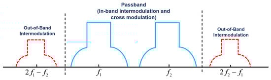
Figure 1.
Output power spectrum of dual-band signals including out-of-band intermodulation.
In this article, we derived an explicit expression of the spectrum regrowth for the amplified dual-band orthogonal frequency-division multiplexing (OFDM) signals including the out-of-band intermodulation. This result expands the previous spectrum model [14] to a larger range outside the passband. While the dual two-tone test in [13,18,19] could be useful for locating the frequency range of the out-of-band interferences, the proposed out-of-band model of dual-band power spectrum could locate and quantify the out-of-band distortions/interferences.
2. Spectrum Model
2.1. Calculating the Correlation for the Dual-Band OFDM Output Signals
Based on ([14], Equation (3)), the input dual-band OFDM signal can be expressed as:
where is the OFDM signal in one band centered at frequency with bandwidth , and is the OFDM signal in the other band centered at with . and are the baseband representation, which equal to and , respectively. The power spectrum density (PSD) of and can be expressed respectively as follows [14]:
and
where and are the powers of and , respectively.
From [14], we know the third-order term of Taylor series model generally dominates in the nonlinear effect. Using the third-order Taylor series model of RF amplifiers ([14], Equation (6)) and (1), the output amplified dual-band OFDM signals are described as:
To simplify the expression of (3), six new terms , , , , , and are defined as:
Using (4)–(9), (3) can be rewritten as:
When the frequency segmentation between the two carrier-frequency bands is large, the last six terms in (10) centered at , , and , respectively, are considered far away from the spectrum bands of interest. Therefore, after the band-pass filtering, the out-of-band spectral components in (10) are removed [14].
In this article, we now consider the situation that the frequency segmentation is small. Therefore, the two terms in (10) centered at and are difficult to be filtered, thus remain in consideration. After the band-pass filtering, the last four terms in (10) centered at , , and , respectively, are far away from the passband and are thus removed using band-pass filtering. Therefore, the filtered spectrum (spectrum near passbands) is truncated to:
From (11), in order to be comparable with the physical measurement, the power spectrum density (PSD) of can be calculated as [14,18]:
Compared to ([14], Equation (19)), the last two terms in are the distortions caused by out-of-band intermodulation. The PSD terms, and in (12), contain linear amplification, in-band IM products, and CM products, which all have already been discussed in [14]. The PSD terms, and in (12), which represent out-of-band intermodulation can be calculated from the correlation functions of and of using Wiener-Khintchine theorem [17] as:
To simplify the calculation, only the derivation of will be explained in detail. can be derived using the similar method. The correlation is defined as:
where is the mathematical expectation of . By substituting (6) into (14), can be expressed as:
can be derived similarly as:
2.2. The Power Spectrum Density of Amplified Signals
By using (13) and (16), can be derived as:
where is defined as the Fourier transform of . Based on ([14], Equations (4), (25) and (49)), and can be described respectively as:
and
By substituting (19) and (20) into (18), can be derived as:
where is the linear part of the output power for and is the linear part of the output power for [11,12], which are
and
Equation (21) describes the PSD of the first left part of the out-of-band intermodulation. Similarly, the right part of the out-of-band intermodulation can be calculated as:
Based on (12), we now could decompose into:
where is attributed to linear amplification, in-band IM and CM, while is attributed to out-of-band only. can be written as ([14], Equation (54)), and the observations related to can be found in [14]. So as to obtain , we need to shift and to carrier frequencies and , respectively. then equals to half of the summation of those two shifted spectrum items as
By comparing ([14], Equation (54)) and (26), it can be seen that the in-band spectra will not be interfered by the out-of-band distortions. In Figure 2, A numerical case is shown with MHz, = 886 MHz, MHz, dBm, dBm, dBm. The blue dash waveform shows without CM and out-of-band intermodulation, and the red solid waveform shows . The difference between the two lines indicates that the impact of out-of-band intermodulation is clear. Also, from Figure 2, we can see that has a clear interference if there are other signals centered around 842 MHz or 908 MHz in those channels.
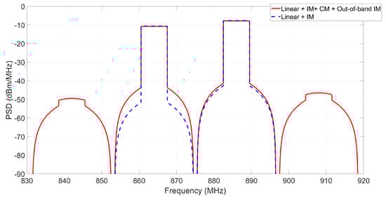
Figure 2.
with and without CM and out-of-band intermodulation.
3. Experimental Setup and Verification
The measurement setup is described in Figure 3, which consists of the Tektronix AWG 70002A arbitrary waveform generator as frequency up-conversion units and DACs, the Tektronix RSA5126B real-time spectrum analyzer for capturing the signal from the output of the RF amplifier for further algorithm verification, the Mini-Circuit LNA ZFL-1000LN+ as the device under test, and a PC running MATLAB to verify the analytical prediction with the experimental measurements.
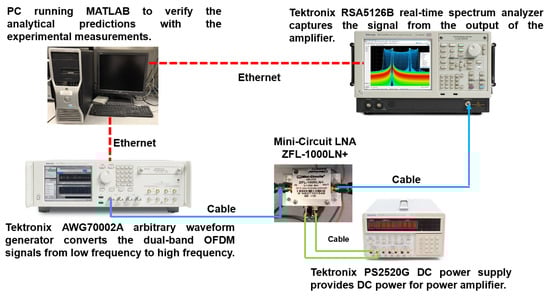
Figure 3.
Experiment setup.
Based on the standards of LTE operating bands [21], a 7 MHz bandwidth with an 864 MHz center frequency was chosen for the left band, and a 7 MHz bandwidth with an 886 MHz center frequency was chosen for the left band. The number of subcarriers for each band is 470. In Figure 4, it can be clearly observed that the theoretically predicted PSD (the red line) matches the experimental results (the blue line).
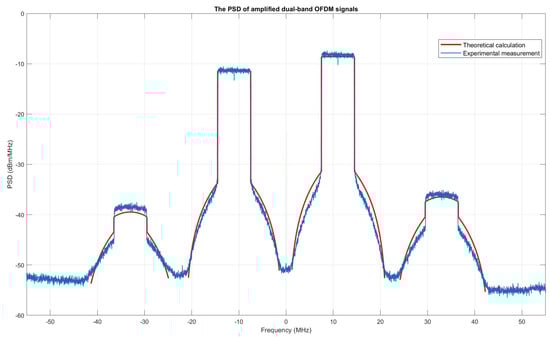
Figure 4.
The red line is the theoretically predicted PSD, and the blue line is the experimental result.
Since only third-order nonlinearity is considered in this manuscript, there are some visible misalignments in the shoulder areas between theoretical calculation and experimental measurement shown in Figure 4. These misalignments are generated by high-order nonlinearities and memory effects.
In order to further improve the accuracy of this model, higher order nonlinearities and memory effects will be considered in our future study.
4. Conclusions
In this article, we expanded our dual-band spectrum modeling, from in-band IM and CM previously, to out-of-band intermodulation, which will be used to evaluate the interference to adjacent channels. The dual-band spectrum model could help spectrum planners and regulators to identify where the interferences will be.
Author Contributions
Conceptualization, Q.W. and X.L.; Data curation, X.Y. and S.Y.; Formal analysis, X.Y.; Investigation, X.Y., S.Y. and F.L.; Methodology, Q.W. and F.L.; Project administration, F.L.; Resources, X.Y., S.Y. and F.L.; Software, X.Y. and S.Y.; Supervision, F.L.; Validation, X.L. and F.L.; Visualization, X.Y. and S.Y.; Writing–original draft, S.Y.; Writing–review and editing, X.Y., S.Y. and F.L. All authors have read and agreed to the published version of the manuscript.
Funding
Publication of this article in an open access journal was funded by the Portland State University Library’s Open Access Fund.
Conflicts of Interest
The authors declare no conflict of interest.
Abbreviations
The following abbreviations are used in this manuscript:
| 5G | Fifth Generation |
| IP3 | third order intercept point |
| CR | Cognitive Radio |
| 4G | Fourth Generation |
| LTE | Long Term Evolution |
| RF | Radio Frequency |
| CM | Cross Modulation |
| IM | InterModulation |
| NR | New Radio |
| DPD | Digital Predistortion |
| OFDM | Orthogonal Frequency Division Multiplexing |
| PSD | Power Spectrum Density |
| SEM | Spectrum Emission Mask |
Appendix A
Using ([14]. Equation (29)), can be expressed as
Substituting ([14], Equations (26) and (35)–(38)) into (21) yields
References
- Negra, R.; Sadeve, A.; Bensmida, S.; Ghannouchi, F.M. Concurrent dual-band Class-F load coupling network for applications at 1.7 and 2.14 GHz. IEEE Trans. Circuits Syst. 2008, 55, 259–263. [Google Scholar] [CrossRef]
- Haykin, S. Cognitive radio: Brain-empowered wireless communications. IEEE J. Sel. Areas Commun 2005, 23, 201–220. [Google Scholar] [CrossRef]
- Kolodozy, P. What is a spectrum hole and what does it take to recognize one? IEEE Trans. Circuits Syst. 2008, 55, 259–263. [Google Scholar]
- Ramani, V.; Sharma, S.K. Cognitive radios: a survey on spectrum sensing, security and spectrum handoff. China Commun. 2017, 14, 185–208. [Google Scholar] [CrossRef]
- Mabrouk, M.B.; Ferré, G.; Grivel, E.; Deltimple, N. Interacting multiple model based detector to compensate power amplifier distortions in cognitive radio. IEEE Trans. Commun. 2015, 55, 259–263. [Google Scholar] [CrossRef]
- Mun, B.; Jung, C.W.; Park, M.; Lee, B. A compact Frequency-reconfigurable multiband LTE MIMO antenna for laptop applications. IEEE Antennas Wirel. Propag. Lett. 2014, 13, 1389–1392. [Google Scholar] [CrossRef]
- Dong, J.; Yu, X.P.; Deng, L.W. A Decoupled multiband dual-antenna system for WWAN/LTE Smartphone. IEEE Antennas Wirel. Propag. Lett. 2017, 16, 1528–1532. [Google Scholar] [CrossRef]
- Jilani, S.; Alomainy, A. A multiband millimeterwave 2-D array based on enhanved franklin antenna for 5G wireless systems. IEEE Antennas Wirel. Propag. Lett. 2017, 16, 2983–2986. [Google Scholar] [CrossRef]
- Niknam, S.; Nasir, A.; Mehrpouyan, H.; Natarajan, B. A multiband OFDMA heterogeneous network for millimeter wave 5G wireless applications. IEEE Access 2016, 4, 5640–5648. [Google Scholar] [CrossRef]
- Ejaz, W.; Ibnkahla, M. Multiband spectrum sensing and resource allocation for IOT in Cognitive 5G networks. IEEE Internet Things J. 2017, 5, 150–163. [Google Scholar] [CrossRef]
- Wu, Q.; Xiao, H.; Li, F. Linear RF power amplifier design for CDMA signals: a spectrum analysis approach. Microw. J. 1998, 41, 22–40. [Google Scholar]
- Liu, C.; Li, F. Nonlinear analysis of OFDM-based wireless systems. In Orthogonal Frequency Division Multiple Access Fundamentals and Applications; Jiang, T., Song, L., Zhang, Y., Eds.; Auerbach: Boca Raton, FL, USA, 2009; pp. 41–67. [Google Scholar]
- Yan, S.; Yang, X.; Li, X.; Li, F. On dual-band amplifications using dual two-tones: clarifications and discussion. IEEE Trans. Instrum. Meas. 2017, 66, 2789–2792. [Google Scholar]
- Li, F.; Yan, S.; Yang, X.; Li, X. Spectrum modeling of cross-modulation for concurrent dual-band RF power amplifiers in OFDM modulation. IEEE Trans. Instrum. Meas. 2018, 67, 2772–2784. [Google Scholar] [CrossRef]
- Zhang, Y.; Zhu, J.; Kinget, P. An out-of-band IM3 cancellation technique using a baseband auxiliary path in wideband LNTA-Based receivers. IEEE Trans. Microw. Theory Techn. 2018, 66, 2580–2591. [Google Scholar] [CrossRef]
- Meredith, J.M. 3GPP TS 38.101-1; Release 15; 3GPP Support Office: Valbonne, France, 2017. [Google Scholar]
- Ma, Y.; Yamao, Y.; Akaiwa, Y.; Ishibashi, K. Wideband digital predistortion using spectral extrapolation of band-limited feedback signal. IEEE Trans. Circuit Syst. 2014, 61, 2088–2097. [Google Scholar] [CrossRef]
- Bassam, S.A.; Helaoui, M.; Ghannouchi, F.M. 2-D Digital Predistortion (2-D-DPD) Architecture for Concurrent Dual-Band Transmitters. IEEE Trans. Microw. Theory Techn. 2011, 59, 2547–02553. [Google Scholar] [CrossRef]
- Amin, S.; Moer, W.V.; Handel, P.; Ronnow, D. Characterization of concurrent dual-band power amplifiers using a dual two-tone excitation signal. IEEE Trans. Instrum. Meas. 2015, 64, 2781–2791. [Google Scholar] [CrossRef]
- Vignat, C. A generalized Isserlis theorem for location mixtures of Gaussian random vectors. Stat. Probab. Lett. 2011, 82, 67–71. [Google Scholar] [CrossRef]
- Signal Research Group. The LTE Standard. Ericsson and Qualcomm. Available online: https://www.qualcomm.com/media/documents/files/the-lte-standard.pdf (accessed on 8 March 2020).
© 2020 by the authors. Licensee MDPI, Basel, Switzerland. This article is an open access article distributed under the terms and conditions of the Creative Commons Attribution (CC BY) license (http://creativecommons.org/licenses/by/4.0/).