Abstract
Internet of Things (IoT) networks consist of tiny devices with limited processing resources and restricted energy budget. These devices are connected to the world-wide web (www) using networking protocols. Considering their resource limitations, they are vulnerable to security attacks by numerous entities on the Internet. The classical security solutions cannot be directly implemented on top of these devices for this reason. However, an Intrusion Detection System (IDS) is a classical way to protect these devices by using low-cost solutions. IDS monitors the network by introducing various metrics, and potential intruders are identified, which are quarantined by the firewall. One such metric is reputation management, which monitors the behavior of the IoT networks. However, this technique may still result in detection error that can be optimized by combining this solution with honeypots. Therefore, our aim is to add some honeypots in the network by distributing them homogeneously as well as randomly. These honeypots will team up with possible maliciously behaving nodes and will monitor their behavior. As per the simulation results, this technique reduces the error rate within the existing IDS for the IoT; however, it costs some extra energy. This trade-off between energy consumption and detection accuracy is studied by considering standard routing and MAC protocol for the IoT network.
1. Introduction
It is foreseen that several billions of tiny devices will be linked to the Internet soon ([]). These devices have limited processing resources and restricted energy budget, but they may positively change the way we live right now. Owing to limited resources, they are a possible target of malicious intruders. These intruders cause network traffic disruption leading to a non-functional network. Hence, it is a prime requirement to secure these devices without losing a lot of resources while implementing an application []. One such attack is a Denial-of-Service attack, where the attacker causes disruption in network traffic by either dropping the packets or by selectively forwarding the packets [].
To implement a low-cost solution, we consider a class of applications based on reputation management [].With this type of solution, a reputation is built for all the participating IoT nodes by considering their past interactions with their neighbors. If a node is involved in dropping or selectively forwarding the packets, then it is labeled to be malicious by its neighbors and its reputation starts to fall below a certain threshold. If reputation decreases severely, then it is removed from the network by a firewall. However, this may lead to trust-based attacks where malicious nodes can give wrong reputation values for a good node and this may decrease detection percentage []. Therefore, in case of trust-based attack, the central authority tasks some nodes to see if there is a trust-based attack going on in the network. These devices act like honeypots and their behavior may help in decreasing the errors in reputation-based solutions. Here it is pertinent to mention that as per [], a honeypot is defined as: “It is a system that captures and identifies malicious activities by simulating a real system or protocol.” These honeypots reduce the detection error in the reputation-based solution. However, these honeypots may consume resources in terms of energy consumption and processing time. Therefore, it is required to analyze various parameters so that optimal resources are allocated for minimizing the detection error.
Our target is to consider a tree, which is formed by the Routing Protocol for Low power and Lossy networks (RPL) []. The nodes are attached to this tree, and the traffic is forwarded to the central node, which is called a border router. If a node is dropping packets, as described previously, then its reputation starts to fall. The border router constantly monitors the network and some honeypots are installed in the network to monitor the malicious nodes. These will facilitate in tracking down the maliciously behaving nodes.
In this article, we first explain the related work in the Section 2, which comprises of a discussion on the RPL routing protocol, the IEEE 802.15.4 protocol, the possible threats/solutions against IoT networks, and the honeypots for the IoT networks. Later, we propose a honeypot-based reputation management for the IoT network in Section 3. Section 4 explains the battery lifetime estimation process for the CC2480 device employing the IEEE 802.15.4 protocol. Finally, we explain the results obtained from the simulations in the Section 5 and the article is concluded in the Section 6. The nomenclature and abbreviations used in paper are given in Nomenclature and Abbreviations in the final part of the paper respectively.
2. Related Work
This section discusses wide range of topics, which are necessary for understanding the low-cost solutions for the IoT security. In the first subsection, the RPL routing protocol and the IEEE 802.15.4 protocol are described, which are usually employed in routing and MAC layers of the IoT network, respectively. Then in the next subsection, we narrate the possible threats and security solutions against IoT networks. Finally, the honeypot-based solutions for the IoT network are detailed in the third subsection.
2.1. Routing and MAC Layer protocols for the IoT Network
To evaluate an IoT network, it is important to consider standard routing and MAC layer protocols for IoT networks. RPL protocol and IEEE 802.15.4 are used for routing and MAC layer in the IoT networks. Therefore, in this section, we describe both protocols in detail below:
2.1.1. RPL Protocol
The RPL is a protocol based on distance vector routing and it targets Lossy and Low Power Networks. The hierarchy of the RPL protocol is based on Destination Oriented Directed Acyclic Graph (DODAG) [,]. All the nodes are connected to a central node, called border router, using a tree-based structure. The tree construction is based on an objective function, which depends upon multiple metrics for choosing the best route towards the border router. It is possible that multiple DODAG trees exist in a network for forwarding different types of traffic []. The RFC document [] explains the selection of a parent based on an objective function. This optimizes the tree by considering different metrics like energy consumption, hop count, link quality, etc. []. The construction and maintenance of the DODAG tree are carried out by the DODAG Information Object (DIO) messages.
The DODAG construction is done by the border router []. Some control messages are generated for exchange of information concerning the DODAG construction. DODAG Information Solicitation (DIS), DODAG Information Object (DIO) and Destination Advertisement Object (DAO) are some of these messages. The border router initiates DIO messages for commencement of DODAG hierarchy. Some nodes receive this message. Based on their objective function, the nodes may or may not join the DODAG. If it joins the DODAG tree, then it can communicate with the border router. It also calculates its position in the DODAG and it further initiates DIO messages, so other nodes can join the tree as well. A rank is assigned to each node by considering its position with respect to the border router in the DODAG. This also helps in avoiding the loop formation in the network [].
On the other hand, if a new node wants to join the DODAG, then its procedure is different. It will broadcast DIS messages to its neighbors. The neighbors will reply using DIO messages, which have information about the DODAG tree. In addition, the DIO messages are also broadcast periodically, so that a node may wait for this broadcast if it wishes to join the DODAG tree. The trickle algorithm determines the rate at which these messages can be broadcast. It makes sure that fewer DIO transmissions are made to have a stable DODAG tree. The DIO message also specifies the rank of the parent node. In case multiple DIO messages are received, the rank of the potential parent node helps in choosing the next hop. At the end, a DAO message is sent from the joining node towards the border router. Every node which receives this packet, forwards it towards the border router.
There can be an occurrence of a loop in the DODAG tree, and it should be minimized. It is done by ignoring the messages sent by a child node traveling downwards. Furthermore, a node is allowed to switch parent if it improves its rank. Rank inconsistencies are detected by data path validation. Special flags (’O’ flag) indicate the expected direction of the packet. If there is a mismatch in ’O’ flag and ’R’ flag on a packet, then an inconsistency in rank has occurred. Once a loop is detected, the DIO messages are initiated for removing this loop [].
A global or local repair mechanism is initiated once a node disappears due to lack of battery power. The DODAG is entirely built by increasing version number in DIO messages for global rebuild procedure. If a node receives this message with newer version number, it must join the DODAG tree. However, global rebuild is costly in terms of energy consumption. Therefore, some local rebuild procedures also exist in the case of node disappearance. These procedures include routing through same neighbor, or another approach is to switch neighbors. An example DODAG network is shown in Figure 1.
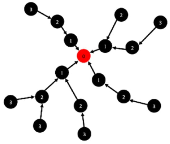
Figure 1.
DODAG Network.
2.1.2. IEEE 802.15.4 MAC Protocol
The IEEE 802.15.4 Protocol [] is used for connecting various devices that are part of Personal Area Networks (PAN). This is a data link layer protocol that is primarily used for this type of interconnection. Carrier Sense Multiple Access with Collision Avoidance (CSMA/CA)-based channel access mechanism is used in the IEEE 802.15.4 protocol. It provides a simple and effective mechanism other than random access algorithms, by avoiding unstable channel conditions. In the case of real-time data traffic, it also supports the provision of Guaranteed Time Slots (GTS). There are two types of devices supported by the protocol:
- Full-Function Devices (FFD) support all the communication properties.
- Reduced-Function Devices (RFD) support tiny devices with lower performance characteristics.
The network is managed and controlled by a PAN coordinator, which is an FFD. The protocol supports network beaconing, as the PAN coordinator broadcasts special messages, called beacons, periodically after beacon intervals (BI). That is how the other nodes of the network synchronize with the coordinator. The active channel listening also costs network a lot of energy, therefore, the protocol offers reduced channel listening by declaring certain percentage of BI as passive. As no packets are sent, received or forwarded in this time frame, hence, nodes may stop listening to conserve their energy.
The packets in the IEEE 802.15.4 standard are termed as MAC Protocol Data Units (MPDU). These are of four types, i.e., data transfer, network beacons, acknowledgment, and MAC command frames. A superframe is sent between two beacons for synchronization of nodes in the network. Its example is given in Figure 2. The first part is the Contention Access Period (CAP), while the second one is called the Contention Free Period (CFP). CAP controls the channel access of the nodes by using CSMA/CA in this period. CFP is optional and it is activated if a node requests time slots. There are 16 slots of equal length in the superframe. The coordinator may allow a node to use two slots in a superframe and it can support up to eight nodes. Thus, the nodes which require sending data in real time are served using GTS.
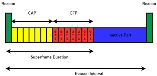
Figure 2.
Superframe Structure for Beacon Enabled mode in the IEEE 802.15.4 - An Example.
The beacon enabled node reduces idle listening as a node is required to listen in a time slot applicable to it. On the contrary, the coordinator cannot go to the sleep mode as it must provide the necessary management to other nodes.
There is also a non-beacon enabled mode supported by the IEEE 802.15.4 protocol. There are no beacons in the protocol; however, the devices use unslotted CSMA/CA for communicating with the coordinator. The tasks of the coordinator are to manage device association and disassociation. This is an important mode of the protocol, but it does not support real-time data delivery. In addition, all the IoT devices must listen constantly to the channel.
2.2. Threats and Low-Cost Security for the IoT Network
To propose a useful security solution, it is important to consider cyber-attacks that are possible against IoT networks. In addition, it is pertinent to discuss low-cost security solution for IoT networks. Therefore, in this section, we discuss low-cost security solutions and threats which exist for the IoT network.
2.2.1. Low-Cost Security Solutions for the IoT Networks
The IoT network is at risk of security attacks by malicious nodes. There is a need to protect the network by considering its weak points. One of the drawbacks of the IoT and Wireless Sensor Networks is their limited processing and energy resources [,]. The classical security solutions may cost a lot of energy. Hence, there is a need to look for other solutions that can protect IoT networks. For example, Ref. [] proposes a low-cost energy efficient solution for detecting motion using PIR (passive infrared) sensor. The system, which includes security nodes, is activated after the motion is detected, and it remains in idle mode otherwise. That is how the energy is minimized in the system. Similarly, Ref. [] compares flow-based with packet-based security systems for the IoT, and claims that flow-based systems are more superior and have less processing cost. Recently, some researchers have started to look for solutions that are based on reputation management []. Reputation of each node is developed, based on their past interactions. If a node is involved in malicious activities, it will be quarantined from the rest of the network. We have used a similar solution to include the role of honeypots in the network. This will significantly enhance the results obtained previously.
2.2.2. Threats against the IoT Networks
In this section, we discuss the threats that exist for the IoT networks. Our focus, however, is only on routing attacks and reputation model attacks only:
Routing attacks against IoT Networks: There are multiple routing attacks that can be performed on routing protocol. In the following, these attacks are detailed out:
- Selective-Forwarding Attacks: [,] discusses the Selective-Forwarding Attacks. It is initiated by an attacker by selective-forwarding packets, e.g., forwarding only data traffic and dropping rest of it. This attack can be avoided by making sure that the malicious node is not involved in packet forwarding. Another way is to hide the packet’s type, so that malicious node is unaware of the packet’s type.
- Sinkhole Attacks: These types of attacks are described in [,]. A sink broadcasts a message for a false path for attracting more data traffic. However, on receiving all the traffic, the attacker does not forward it. Rather, it drops all the packets. This creates a non-functional network leading. However, this attack can be minimized by using reputation mechanism described above.
- Version Number Attacks: In an RPL-based routing protocol, a version number attack [] can be initiated. The border router uses a version number to control the repair process of the DODAG tree. An attacker can change this field by announcing a new version number, which may cause confusion about a wrong version number. This would disrupt the network, and it will deplete the energy resources of the network.
Trust-based attacks against Reputation Management: For the case of reputation management, an attacker can initiate an attack to destroy the trust between nodes. There are mainly three types of attacks that can be initiated against a solution involving reputation management [] for RPL protocol:
- Self-promoting attacks: To attract more data traffic, the attacker announces a better recommendation for itself. Once traffic is forwarded to the attacker, it can then launch selective-forwarding or sinkhole attacks.
- Bad-mouthing attacks: Another goal of the attacker is to target good nodes by decreasing their reputation. To do so, the attacker may ruin the good node’s reputation by giving false values of the trust values. If successful, the other nodes will not forward the traffic via that good node.
- Ballot-stuffing attacks: Finally, another strategy of the attacker is to falsely enhance the reputation of other attackers by providing false trust values. This will help in launching a coordinated attack by these malicious nodes.
2.3. Honeypots for the IoT network
In this subsection, we discuss the honeypot-based solutions that exists in the state-of-the-art for the IoT networks. As mentioned earlier, honeypot is a system that captures the behavior of malicious activities in the network. Here, we discuss various honeypot solutions that exist for IoT devices.
Machine learning techniques to detect malware using honeypots is explained in []. The machine learning model is trained by data that is gathered by the honeypot, which is used for detecting Distributed Denial-of-Service (DDoS) attacks in the network. However, Ref. [] deployed three different types of honeypots based on router service available in the network and it is deployed in practice for detecting unknown malicious attacks. Moreover, Ref. [] implements a honeypot for DoS attacks in the main server of the IoT system, which helps in avoiding complete shutdown of the system. Similarly, Ref. [] introduces a honeypot which uses Universal Plug and Play (UPnP) protocol. The honeypot is freely available under open-source license and it emulates real IoT devices.
Another solution proposed in [], implements a honeypot for telnet attacks on IoT devices. It is based on multi-component design for attaining exposure to malicious activities in the network and is tested using Mirai. However, Ref. [] defines the honeypot by taking into account the behavior of an attacker. As an attacker might abort its attack if it detects the presence of a honeypot. Therefore, the article proposes honeypot creation by considering probabilistic estimation of honeypot detection. A Zigbee gateway-based honeypot is created in [], as most of the IoT devices use this protocol at data link layer. The honeypot captures traffic for analysis and compares the individual versus mass attacks in the IoT system. Moreover, [] uses a decoy-based technology for implementing a honeypot using Raspberry pi for improving security at low cost.
Most of the above-mentioned solutions implement a honeypot for detecting the behavior of the attacker. However, there are another honeypot-based solutions which analyze other parameters as well. For example, [] exploit neighboring mobile devices for creating virtual IoT nodes, which act as real and fake IoT nodes. The main aim is to confuse the attacker and it successfully aims at reducing the attack on the network. Another article [] describes a game theory-based solution for deception involving an attacker and honeypot. The game theory is used to model its interaction for optimally trapping an attacker.
To the best of our knowledge, honeypots are not used in any previous reputation-based system. Therefore, we propose a solution using honeypot in a reputation-based solution for mitigating detection error.
3. Honeypot-Based Reputation development for Intrusion Detection in the IoT
An unauthorized activity initiated in a network by an attacker can be achieved in either active or passive manner and it is termed as an intrusion. Passive attacks take out important information from the network without damaging it. On the contrary, active attacks harm the network communication by dropping and tempering the data packet []. The IoT network has limited system resources in terms of processing power, battery capacity and communication bandwidth, hence, it will lose severely in the case of an intrusion. There is another need to design a system that can protect the IoT network without losing a lot of precious resources. Reputation Management is a way to protect the IoT system without using a lot of these resources. If combined with the honeypots, then it can further enhance the performance of the system. In this section, we first describe a reputation management system for the RPL-based IoT network. Then, we shall introduce honeypots in several ways to inquire about their performance.
3.1. Reputation Management for the RPL protocol
In this section, we shall describe the approach for trust development in the RPL protocol. The approach is inspired by [] and it considers the cyber-attacks on RPL described in Section 2.2.We make the following assumptions:
- The nodes support idle mode listening for neighboring traffic.
- The malicious nodes are involved in routing attacks described previously.
To explain the model, we assume nodes a, b and c are involved in a communication as indicated in Figure 3. As a node a wants to forward a packet to node c, through node node b. If node b is involved in a routing attack, it will not send the packet to node c; however, due to the nature of wireless medium, the node a will realize the attack. It will, therefore, reduce its trust on node b. On the other hand, if the packet is forwarded correctly, then node a will have more trust on node b and its trust will eventually increase. An example of monitoring algorithm is explained in Algorithm 1.
| Algorithm 1 Security Monitoring |
| while do if then if then if Packet is forwarded towards next hop then else end if end if end if end while |
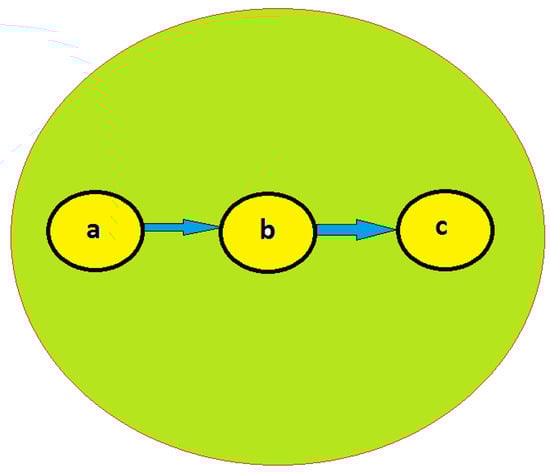
Figure 3.
Radio Transmission Range of node b.
That is how; each node calculates three metrics, i.e., belief, b, disbelief, d and uncertainty, u for a certain node using the model described in []. The belief of node i on node j increases after a successful interaction with a particular node, while disbelief of node i on node j increases in the case of unsuccessful interaction. If an interaction did not happen between the nodes, then the uncertainty of node i on node j would increase. The formulas of these three factors are given below:
Here, successful and failed interactions between nodes i and j is described by and , respectively. However, uncertainty is described by . For example, if a node i forwards the traffic of node j to the next hop then it is counted as a successful interaction. On the other hand, if node i deliberately drops the traffic of node j then it is involved in an attack and it is counted as a failed interaction. Finally, if node i cannot judge whether a packet is forwarded by j, then this increases the uncertainty about that iteration. These values are passed to the border router, which calculates the overall recommendations of the nodes. The consensus operator described in [], which is commutative and associative, is used to combine these values and is given below:
It is based on recommendations by two different nodes, and . The values and describes the recommendation; however, while k is equal to .
3.2. Insertion of Honeypots for Reputation Management in RPL
There are some classical solutions, which inject some malicious packets into the network. This includes honeypots of different size, which can deceive malicious devices to quarantine them from the network. The functions of honeypot are as follows:
- Monitor Nodes involved in malicious activity.
- Gain the trust of bad nodes by decreasing reputation of good nodes, and increasing the reputation of bad nodes.
In this article, we consider two placement strategies of the honeypots for evaluating the proposed approach. These are described below:
3.2.1. Random Honeypots placement for the RPL
In the first method, the honeypots are randomly placed in the network. The network is analyzed to see the behavior of such a placement. The algorithm for placing random honeypots is described in Algorithm 2. To implement this method, the border router calculates the reputation of each node in the network. If the reputation of a node falls below a certain level, some randomly selected trusted nodes are activated as honeypots by the border router. These trusted nodes have a very high reputation and confidence value. The honeypots are informed via control packets using the routing tree of the RPL protocol. These nodes will monitor the network traffic to see whether a node is actually malicious or not. The accuracy of these honeypots depends on their listening range, which can be increased by enhancing the transmission range of the network. The network will be analyzed for battery life and detection accuracy of the reputation solution using honeypots.
| Algorithm 2 Reputation Management in RPL for Randomly placed Honeypots |
| if Periodic Trust packets are received from member nodes then Combine trust values for every member node to compute its reputation if the Reputation of a certain node falls below a threshold then Activate randomly placed Honeypots in the network end if end if |
3.2.2. Homogeneous Honeypots placement for the RPL
In this method, the honeypots are placed at specified homogeneous locations in the network. They are basically evenly distributed in the network. The network is analyzed to see the behavior of such a placement. The algorithm for homogeneous placement of honeypots is described in Algorithm 3. Once the reputation of a node falls below a certain threshold, these honeypots are activated by the border router, using specific control packets. The network is monitored by these honeypots to monitor trust-based attacks. The technique is analyzed for detection accuracy and battery lifetime later.
| Algorithm 3 Reputation Management in RPL for Homogeneously placed Honeypots |
| if Periodic Trust packets are received from member nodes then Combine trust values for every member node to accumulate its reputation if the Reputation of a certain node falls below a threshold then Activate homogeneously placed Honeypots in the network end if end if |
Two strategies are adopted from [] for trust and reputation management. The first one is called neighbor-based trust dissemination (NTD) and the second one is cluster-based trust dissemination (CTD). In NTD, trust management is dependent on monitoring the behavior of neighbors. However, CTD considers clusters for trust management in the network. When NTD is combined with the honeypots, then this solution is called Honeypot-based NTD (HNTD). Similarly, honeypot-based solution for CTD is termed as HCTD. In the following, the NTD, CNTD, CTD and HCTD are analyzed for the efficiency of honeypots for trust management. Furthermore, the effect of honeypot placement on energy efficiency is also discussed.
4. Battery Lifetime Estimation for the IEEE 802.15.4
We describe the estimation of battery lifetime for CC2480-based IoT devices. The medium access control for CC2480 employs the IEEE 802.15.4 protocol. It is inspired by [] and [] and it considers three cases for energy estimation, i.e., best, worst and average case. The process is explained below:
4.1. Best Case
For considering the best case, it is assumed that channel is available as soon as a packet needs to be transmitted. The mote transmits a frame when an idle channel is detected. To transmit a frame with a data payload of n bytes, it is assumed that time is needed. This time is calculated as follows:
In this equation, r is the rate of data transmission for IEEE 802.15.4, with value of 250 kbps in ISM 2.4 GHz band. denotes the total overhead and it includes frame delimiter, MAC header, CRC field and preamble for an IEEE802.15.4 frame, with a value of 31 bytes.
The amount of current required by the CC2480 device to transmit n bytes is given by following equation:
where with a value of 13 ms, means the time required by the CC2480 transceiver for waking up and turning off. The current required for this activity is represented by and its value is 13 mA. The current required by the transceiver during transmission of n bytes is indicated by , with value of 30.5 mA. indicates the time of the activity period and is given by following equation:
The mean drain current of the battery is given by:
where T represents the time between two successive transmissions of data (also called update period), and represents the sleep mode current. In addition, the term represents the duty cycle of the device. The battery lifetime L (in hours) with capacity C (in mAh) can be obtained using following equation []:
Here, the current required in the startup phase is neglected and we assume only upstream traffic. The typical capacity of 1200 mAh, which is provided by two AA batteries is considered.
4.2. Average Case
To estimate the battery lifetime for an average case, the main parts to be considered are the frequency of collisions and the failures in channel access. If we assume that these factors are self-uncorrelated and independent stochastic processes, then we can use the equations described previously for best case to calculate average case transmission and listening periods. If packet collision probability is represented by and the probability that the channel is occupied in the course of the Clear Channel Assessment (CCA) operation, then the average time required by the CC2480 transceiver for transmitting a packet is computed as follows:
In this equation, the probability a channel access failure is denoted by and maximum number of times the CSMA algorithm is invoked after the first CCA failure is represented by . It is pertinent to note that the is calculated after mMaxb+1 CSMA waits and mMaxb+1 failed CCA operations. Thus, is estimated as:
Here mean transmission time that ended up in a channel access failure is denoted by and it is calculated after CCA failures and CSMA waits.
By default, the terms and are assigned the values of 3 and 5, respectively []. These terms represent the initial and maximum values of , the backoff exponent, respectively. The value of is estimated to be 19.04 ms, by using the default values of mMaxb, macMinBE and macMaxBE. The mean expected delay for the CSMA/CA algorithm and CCA operations of a transmission endeavor, which does not result in channel access failure is represented by . This can be computed as follows:
For n data bytes, the mean time for CC2480 transceiver in transmission state is calculated as follows:
The mean number of time a packet is transmitted is given by summation . As per [], the values of and are taken as 0.25.
4.3. Worst Case
If the successful transmission of a frame is done in the last transmission attempt, then it is considered to be the worst case. The worst-case listening time of the CC2480 radio transceiver is computed as follows:
The maximum number of times a transmission is attempted is expressed as . As per IEEE 802.15.4 standard, is set to a value of 3. If a transceiver switches from the transmission to reception (or vice versa), then the corresponding time is called turnaround time and is represented by , with value of 0.192 msec. If the receiver waits for the ACK packet before re-sending the packet, then corresponding time is represented by , with value of 0.864 msec. The term represents maximum delay in each transmission attempt, which may be introduced by the CSMA/CA algorithm and CCA operation, and it is calculated as follows:
The default value of is 4 as per the standard. denotes time required by the CCA operation, with a value of 0.128 ms. However, the backoff period is denoted by and its value is 0.32 s. Using these values, and are calculated as 153.98 ms and 37.44 ms, respectively. The maximum time that the CC2480 transceiver remains in successful transmission mode (by considering retransmissions) is calculated as:
The battery lifetime can be estimated using these equations.
5. Simulation Results
The OCTAVE [] is used to analyze the three approaches described before and the simulation parameters are described in Table 1. OCTAVE is a mathematical and scientific software tool, with powerful plotting and visualization features. It is free software that executes on operating systems like GNU/Linux, macOS, BSD, and Windows. As the OCTAVE is mostly compatible with MATLAB [], therefore, simulation model used in this article is inspired by MATLAB simulations described in [,,].

Table 1.
Simulation Parameters.
In this section, we compare the HNTD and HCTD with the representative related work. The two strategies for comparison are adopted from [] and they are termed as NTD and CTD. In the following, the NTD, CNTD, CTD and HCTD are compared for intruder detection accuracy. In addition, the effect of honeypot placement on energy efficiency is also described.
The simulation scenario consists of 1000 nodes, which are randomly placed in a 100 m × 100 m network. The simulation parameters are inspired by other articles where other IoT protocols are investigated [,]. We vary the number of intruder nodes, and the simulation results are presented next. The detection results as well as energy consumption analysis is explained in following sections:
5.1. Analysis of Honeypot-Based Reputation Management
The results of honeypot-based reputation management are presented in this section, using the simulation parameters are described previously. Following five parameters have been employed to access the algorithms:
Number of Intruders Detected: This parameter determines the number of intruder nodes that have been identified.
False Positives: This parameter indicates number of non-intruder nodes that have been identified as intruder.
False Negatives: This parameter accounts for number of intruder nodes that have been identified as non-intruder.
Undetected Positives: This parameter indicates number of intruder nodes that could not be identified as either an intruder or a non-intruder due to lack of trust values.
Undetected Negatives: This parameter determines number of non-intruder nodes that could not be identified as either an intruder or a non-intruder due to lack of trust values.
We consider two cases for simulation, i.e., homogeneously and randomly placed honeypots. The results are described below:
5.1.1. Homogeneously Placed Honeypots
In this section, we consider the case of nine homogeneously placed honeypots as described in Algorithm 3. Figure 4 and Figure 5 plots number of false negatives and false positives, respectively, by varying intruder nodes in the network. The false positives are obtained by changing the listening range from 10 m to 25 m. Generally, the CTD and HCTD has lower performance than NTD and HNTD. This is because they have lesser monitoring to do. However, on increasing the listening range to 25 m, the number of false negatives decreases to zero. This is because the homogeneously placed honeypots have access to the transmission range of all the malicious nodes and they can verify their behavior. If a malicious node is actually a good node, but its reputation is fallen below a certain threshold due to trust-based attacks, then it can be updated by the honeypot to the border router. Similarly, if a bad node gets a good reputation, then it can also be monitored by the honeypot once its listening range is up to 25 m. This will eventually decrease the false positives and false negatives in the network.
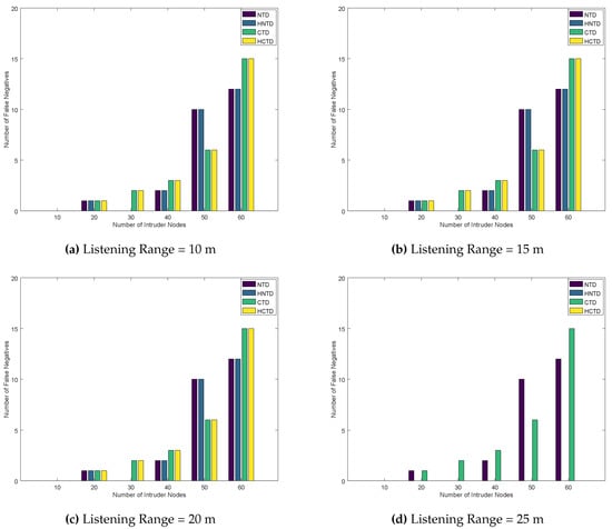
Figure 4.
Number of False Negatives for Homogeneously placed Honeypots.
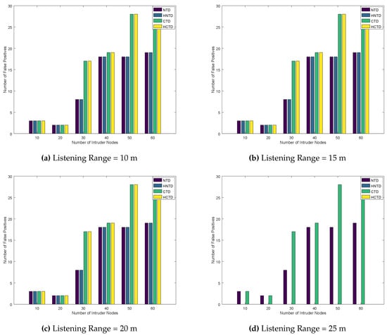
Figure 5.
Number of False Positives for Homogeneously placed Honeypots.
The listening range does not have a significant effect on the detection of intruder nodes by the four techniques. This is explained in Figure 6. However, for most of the cases, detection rates of NTD and HNTD are better than CTD and HCTD.
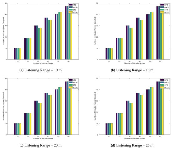
Figure 6.
Number of Intruder Nodes Detected for Homogeneously placed Honeypots.
Finally, the number of undetected negatives and undetected positives are plotted in Figure 7 and Figure 8, respectively. As the listening range is increased, we see a significant correction in these results when the listening range is 25 m or above. Thus, for the given configuration, 25 m are a better listening range for honeypots to have better results, because the honeypots can detect most of the nodes. This helps the honeypot to correct the error in detection. Moreover, it is also concluded that the CTD and HCTD has lower performance than NTD and HNTD. As the NTD and HNTD monitors all the traffic that is being forwarded by the neighboring nodes.
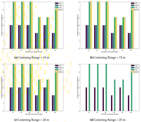
Figure 7.
Number of Undetected Negatives for Homogeneously placed Honeypots.
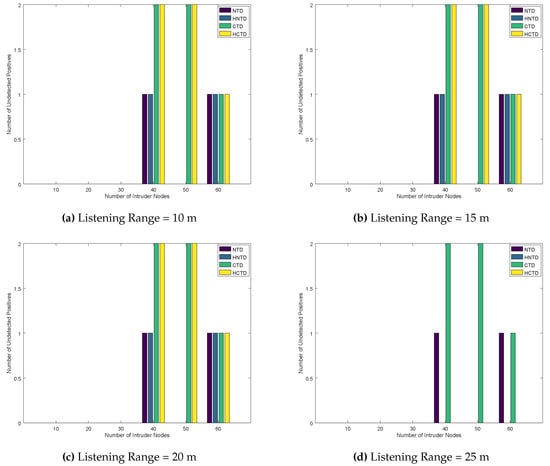
Figure 8.
Number of Undetected Positives for Homogeneously placed Honeypots.
5.1.2. Randomly Placed Honeypots
In this section, we deploy nine honeypots randomly in the network as described in Algorithm 2 and explain the simulation results. Figure 9 and Figure 10 plot number of false negatives and false positives, respectively, by varying intruder nodes in the network. The false positives are obtained by changing the listening range from 10 m to 25 m. Generally, the NTD and HNTD have better performance than CTD and HCTD. This is because they have lesser monitoring to do. However, if the listening range is increased to 25 m, the number of false negatives decreases to zero. As the honeypot is now able to monitor the nodes up to 25 m, therefore, it can detect more errors. These errors are caused by trust-based attacks and it results in bad nodes looking good and vice versa. As a result of honeypot deployment, these errors are reduced, leading to a better solution for reputation management in the IoT network.
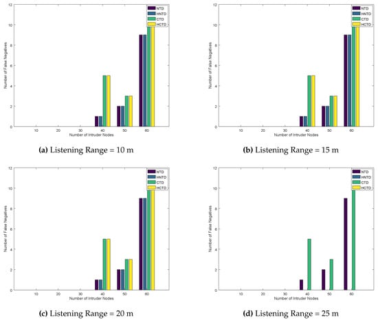
Figure 9.
Number of False Negatives for Randomly placed Honeypots.
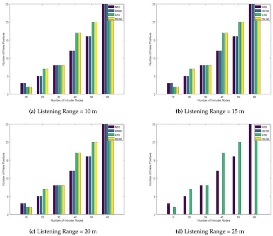
Figure 10.
Number of False Positives for Randomly placed Honeypots.
The listening range does not have a significant effect on the detection of intruder nodes by the four techniques. This is explained in Figure 11. However, for most of the cases, the detection rate of NTD and HNTD is better than the CTD and HCTD.
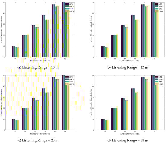
Figure 11.
Number of Intruder Nodes Detected for Randomly placed Honeypots.
Finally, the number of undetected negatives and undetected positives are plotted in Figure 12 and Figure 13. As the listening range is increased, we see a significant correction in these results when the listening range is 25 m or above. Thus, for the given configuration, 25 m are a better listening range for honeypots to have effective results. Again, increasing the listening range of honeypot enables it to detect the trust-based attacks in the network, which yields better results for undetected negatives and undetected positives. Lastly, the CTD and HCTD has lower performance than NTD and HNTD because of less monitoring overhead.
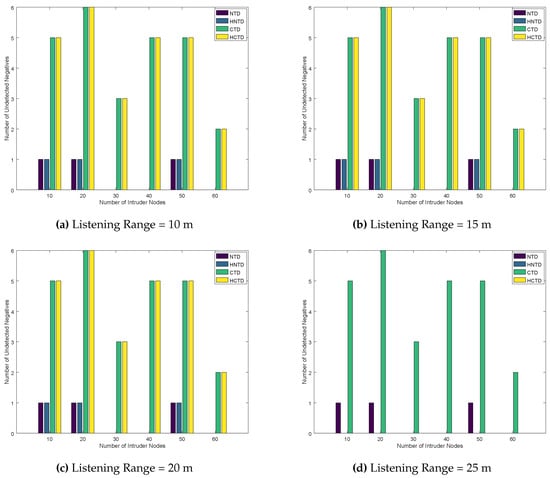
Figure 12.
Number of Undetected Negatives for Randomly placed Honeypots.
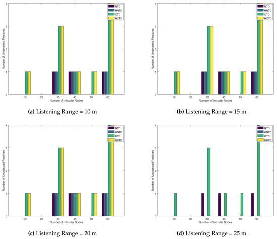
Figure 13.
Number of Undetected Positives for Randomly placed Honeypots.
5.2. Energy Consumption Analysis
To increase listening range, we must tune the transmission power of every node. In this example, we show that by increasing the transmission power of the nodes has a positive effect on the trust-based results. The change in transmission current is predicted using the following equation of free-space model []:
That is, the transmission range varies as per this equation if a free-space model is used. If we choose a particular IoT device for an application, then its transmission range is configured as per its characteristics. However, in this article we select the generalized free-space model to estimate transmission current and this estimation technique would be valid for any type of IoT device. The Figure 14, Figure 15 and Figure 16 show the estimated battery lifetime for best case, average case and worst case, respectively.
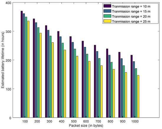
Figure 14.
Estimated Battery Lifetime—Best Case.
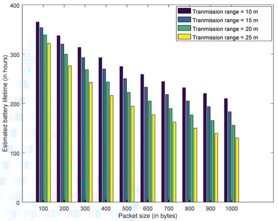
Figure 15.
Estimated Battery Lifetime—Average Case.
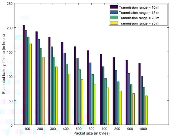
Figure 16.
Estimated Battery Lifetime—Worst Case.
Similarly, Figure 17, Figure 18 and Figure 19 explain the estimated drain current for best case, average case and worst case. Increasing the transmission range from 10 m to 25 m decreases the battery lifetime and increases the drain current. As transmission range is increased by augmenting the transmission power of the IoT devices. However, this decrease in battery lifetime and increase in transmission range has a positive effect on honeypot-based trust management. This cost needs to be considered for deploying the honeypots in the network. Furthermore, for all the results presented, increasing the packet size has a negative impact on drain current and battery lifetime. As transmitting a larger packet consumes more energy, which leads to increase in drain current and reduction in battery lifetime.
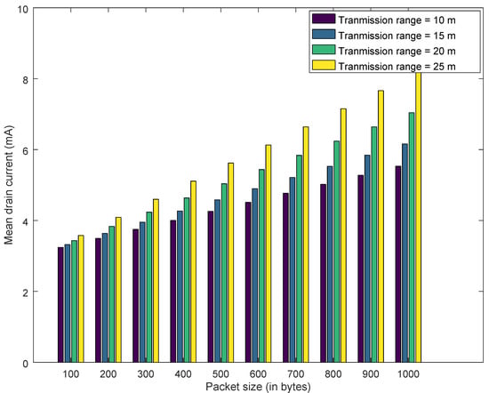
Figure 17.
Required Current for the device—Best Case.
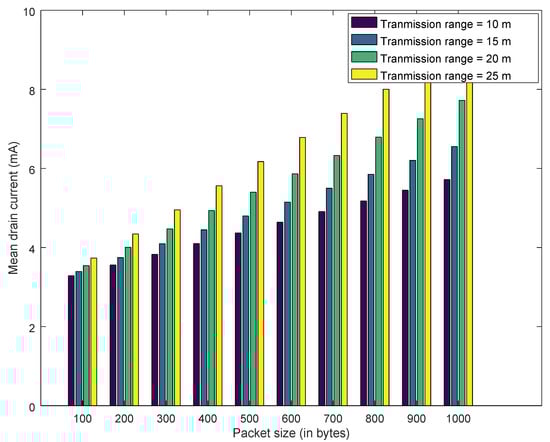
Figure 18.
Required Current for the device - Average Case.
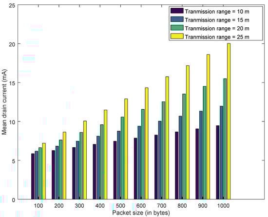
Figure 19.
Required Current for the device - Worst Case.
6. Conclusions
In this article, we used honeypots for reputation management in IoT network. In our previous work, we concluded that reputation management has less overhead for securing IoT network, but there are detection errors. However, these results can be further optimized by using honeypots for reputation management. We showed that adding honeypots will be better if a proper transmission range for transmission/reception is selected. However, increasing transmission range consumes significant amount of energy, which needs to be considered. Thus, there is a trade-off between reducing the detection error and battery lifetime. If a proper detection range is not selected, then the devices are going to consume more energy than required. Hence, it is necessary to consider a better transmission range of devices once honeypots are deployed. This range can be selected for a particular type of node based on the techniques, which are presented in this article. Furthermore, it is also concluded that the cluster-based techniques for monitoring the network traffic has less overhead. However, it results in lower detection accuracy and higher error rate. Finally, it is deducted that another way to optimize the results is by increasing the number of honeypots in the network, but it is a costly solution.
The presented solution is significantly different from the honeypot-based solutions that are described in the related work. Most of those solutions discuss the implementation of honeypots for detecting new types of cyber-attacks on IoT systems. Either they change the number of honeypots, or use machine learning tools to capture new attack patterns. On the other hand, some solutions confuse the attacker by changing the behavior of honeypot as either a good or a bad node. Sometimes, they also use game theory for analyzing the honeypot vs. attacker scenario. To the best of our knowledge, we did not find an article where the honeypot-based solution is combined with the reputation management for securing IoT network. Therefore, our solution is significantly different from the available honeypot techniques for the IoT networks. As per the results presented in the article, the proposed solution gives acceptable results for minimizing errors for the intruder detection. However, this comes at a cost of increased energy consumption. Consequently, we can consider IoT devices, which have more energy and processing resources for taking the role of honeypots.
In the perspective work, we aim to evaluate the results by increasing the number of honeypots. Furthermore, we also suggest implementing the proposed techniques on real-world platforms (e.g., [,]) for verification of the presented results.
Author Contributions
Conceptualization, Z.A.K. and U.A.; methodology, Z.A.K.; writing—original draft preparation, Z.A.K.; writing—review and editing, Z.A.K. and U.A.; funding acquisition, U.A. All authors have read and agreed to the published version of the manuscript.
Funding
This work was supported by GPRC, Department of Science. The APC was funded by GPRC Professional Development Fund.
Conflicts of Interest
The authors declare no conflict of interest.
Nomenclature
The following nomenclature is used in this manuscript:
| Belief of node i on node j | |
| Disbelief of node i on node j | |
| Uncertainty of node i on node j | |
| Successful interactions between nodes i and j | |
| Unsuccessful interactions between nodes i and j | |
| Recommendation of node about node x | |
| Recommendation of node about node x | |
| Time required to transmit a frame with a data payload of n bytes | |
| r | Data transmission rate for IEEE 802.15.4 |
| Total MAC overhead | |
| Time required by the transceiver for waking up and turning off | |
| Current required by the transceiver for waking up and turning off | |
| Time required by the transceiver for listening to the channel | |
| Current required by the transceiver for listening to the channel | |
| Time required by the transceiver during transmission of n bytes | |
| Current required by the transceiver during transmission | |
| Time of the activity period | |
| Mean drain current of the battery | |
| Sleep mode current | |
| L | Battery lifetime |
| C | Battery capacity |
| T | Update period |
| aMaxF | Maximum number of times a transmission is attempted |
| Packet collision probability | |
| Probability for a channel access failure | |
| Mean transmission time that ended up in a channel access failure | |
| Mean expected delay for the CSMA/CA algorithm and CCA operations, which does not result in channel access failure | |
| Turnaround time | |
| Receiver waiting time for the ACK packet before re-sending the packet | |
| Maximum number of times the CSMA algorithm is invoked after the first CCA failure | |
| Backoff period | |
| Time required by the CCA operation | |
| Maximum delay in each transmission attempt | |
| macMinBE | Minimum backoff exponent |
| macMaxBE | Maximum backoff exponent |
Abbreviations
The following abbreviations are used in this manuscript:
| BI | Beacon intervals |
| CAP | Contention Access Period |
| CCA | Clear Channel Assessment |
| CFP | Contention Free Period |
| CSMA/CA | Carrier Sense Multiple Access with Collision Avoidance |
| CTD | Cluster-based trust dissemination |
| DAO | Destination Advertisement Object |
| DDoS | Distributed Denial of Service |
| DIO | DODAG Information Object |
| DIS | DODAG Information Solicitation |
| DODAG | Destination Oriented Directed Acyclic Graph |
| DoS | Denial of Service |
| FFD | Full-Function Devices |
| GTS | Guaranteed Time Slots |
| HCTD | Honeypot-based CTD |
| HNTD | Honeypot-based NTD |
| IDS | Intrusion Detection System |
| IEEE | Institute of Electrical and Electronics Engineers |
| IoT | Internet of Things |
| MAC | Medium Access Control |
| MDPU | MAC Protocol Data Units |
| NTD | Neighbor-based trust dissemination |
| PAN | Personal Area Networks |
| RFC | Request for comment |
| RFD | Reduced-Function Devices |
| RPL | Routing Protocol for Low power and Lossy networks |
| UPnP | Universal Plug and Play |
| www | world-wide web |
References
- Velosa, A.; Hines, J.F.; LeHong, H.; Perkins, E.; Satish, R.M. Predicts 2015: The Internet of Things. Available online: https://www.gartner.com/doc/2952822/predicts--internet-things (accessed on 26 February 2020).
- Jing, Q.; Vasilakos, A.V.; Wan, J.; Lu, J.; Qiu, D. Security of the internet of things: Perspectives and challenges. Wirel. Netw. 2014, 20, 2481–2501. [Google Scholar] [CrossRef]
- Raza, S.; Shafagh, H.; Hewage, K.; Hummen, R.; Voigt, T. Lithe: Lightweight secure CoAP for the internet of things. IEEE Sens. J. 2013, 13, 3711–3720. [Google Scholar] [CrossRef]
- Khan, Z.A.; Herrmann, P. A Trust Based Distributed Intrusion Detection Mechanism for Internet of Things. In Proceedings of the 2017 IEEE 31st International Conference on Advanced Information Networking and Applications (AINA), Taipei, Taiwan, 27–29 March 2017; pp. 1169–1176. [Google Scholar]
- Khan, Z.A.; Ullrich, J.; Voyiatzis, A.G.; Herrmann, P. A Trust-based Resilient Routing Mechanism for the Internet of Things. In Proceedings of the 12th International Conference on Availability, Reliability and Security, Reggio Calabria, Italy, 29 August 2017–1 September 2017; pp. 27:1–27:6. [Google Scholar]
- Wang, M.; Santillan, J.; Kuipers, F. ThingPot: An interactive Internet-of-Things honeypot. arXiv 2018, arXiv:1807.04114. [Google Scholar]
- IETF. RfC 6550—RPL: IPv6 Routing Protocol for Low-Power and Lossy Networks. Available online: https://tools.ietf.org/html/rfc6550 (accessed on 26 February 2020).
- IETF. Neighbor discovery for IP version 6 (IPv6), IETF RFC 4861. Available online: https://tools.ietf.org/html/rfc4861 (accessed on 26 February 2020).
- Mohamed, B.; Mohamed, F. QoS routing RPL for Low power and Lossy Networks. Int. J. Distrib. Sens. Netw. 2015, 2015, 6. [Google Scholar] [CrossRef]
- Raza, S.; Wallgren, L.; Voigt, T. SVELTE: Real-time intrusion detection in the Internet of Things. Ad Hoc Netw. 2013, 11, 2661–2674. [Google Scholar] [CrossRef]
- Nahrstedt, K. Internet of Mobile Things: Challenges and Opportunities. In Proceedings of the 23rd International Conference on Parallel Architecture and Compilation Techniques, Edmonton, AB, Canada, 24–27 August 2014; pp. 1–2. [Google Scholar]
- Korte, K.D.; Sehgal, A.; Schönwälder, J. A study of the RPL repair process using ContikiRPL. In Proceedings of the IFIP International Conference on Autonomous Infrastructure, Management and Security, Luxembourg, 4–6 June2012; pp. 50–61. [Google Scholar]
- Mayzaud, A.; Sehgal, A.; Badonnel, R.; Chrisment, I.; Schönwälder, J. A study of RPL DODAG version attacks. In Proceedings of the IFIP International Conference on Autonomous Infrastructure, Management and Security, Brno, Czech Republic, 30 June–3 July 2014; pp. 92–104. [Google Scholar]
- Levis, P.; Patel, N.; Culler, D.; Shenker, S. Trickle: A self-regulating algorithm for code propagation and maintenance in wireless sensor networks. In NSDI’04: Proceedings of the 1st Conference on Symposium on Networked Systems Design and Implementation; USENIX Association: Berkeley, CA, USA, 2014. [Google Scholar]
- Bhar, J. A Mac Protocol Implementation for Wireless Sensor Network. J. Comput. Netw. Commun. 2015, 2015, 697153. [Google Scholar] [CrossRef]
- Khan, Z.A.; Belleudy, C.; Auguin, M. Analytical Model for Energy Consumption Analysis in Grid Based Wireless Sensor Networks. In Proceedings of the 2009 3rd International Conference on New Technologies, Mobility and Security, Cairo, Egypt, 20–23 December 2009; pp. 1–5. [Google Scholar]
- Khan, Z.A.; Abbasi, U. Evolution of Wireless Sensor Networks toward Internet of Things. In Emerging Communication Technologies Based on Wireless Sensor Networks: Current Research and Future Applications; CRC Press: Boca Raton, FL, USA, 2016; Chapter 7; pp. 179–200. [Google Scholar]
- Kumar, J.; Ramesh, P.R. Low Cost Energy Efficient Smart Security System with Information Stamping for IoT Networks. In Proceedings of the 2018 3rd International Conference On Internet of Things: Smart Innovation and Usages (IoT-SIU), Bhimtal, India, 23–24 February 2018; pp. 1–5. [Google Scholar]
- Sivanathan, A.; Sherratt, D.; Gharakheili, H.H.; Sivaraman, V.; Vishwanath, A. Low-cost flow-based security solutions for smart-home IoT devices. In Proceedings of the 2016 IEEE International Conference on Advanced Networks and Telecommunications Systems (ANTS), Bangalore, India, 6–9 November 2016; pp. 1–6. [Google Scholar]
- Karlof, C.; Wagner, D. Secure routing in wireless sensor networks: Attacks and countermeasures. Ad Hoc Netw. 2003, 1, 293–315. [Google Scholar] [CrossRef]
- Wallgren, L.; Raza, S.; Voigt, T. Routing Attacks and Countermeasures in the RPL-based Internet of Things. Int. J. Distrib. Sens. Netw. 2013, 2013, 794326. [Google Scholar] [CrossRef]
- Khan, Z.; Herrmann, P. Recent Advancements in Intrusion Detection Systems for the Internet of Things. Secur. Commun. Netw. 2019, 2019, 1–19. [Google Scholar] [CrossRef]
- Vishwakarma, R.; Jain, A.K. A Honeypot with Machine Learning based Detection Framework for defending IoT based Botnet DDoS Attacks. In Proceedings of the 2019 3rd International Conference on Trends in Electronics and Informatics (ICOEI), Tirunelveli, India, 23–25 April 2019; pp. 1019–1024. [Google Scholar]
- Zhang, W.; Zhang, B.; Zhou, Y.; He, H.; Ding, Z. An IoT Honeynet based on Multi-port Honeypots for Capturing IoT attacks. IEEE Internet Things J. 2019, in press. [Google Scholar] [CrossRef]
- Anirudh, M.; Thileeban, S.A.; Nallathambi, D.J. Use of honeypots for mitigating DoS attacks targeted on IoT networks. In Proceedings of the 2017 International Conference on Computer, Communication and Signal Processing (ICCCSP), Chennai, India, 10–11 January 2017; pp. 1–4. [Google Scholar]
- Hakim, M.A.; Aksu, H.; Uluagac, A.S.; Akkaya, K. U-PoT: A Honeypot Framework for UPnP-Based IoT Devices. In Proceedings of the 2018 IEEE 37th International Performance Computing and Communications Conference (IPCCC), Orlando, FL, USA, 17–19 November 2018; pp. 1–8. [Google Scholar]
- Semic, H.; Mrdovic, S. IoT honeypot: A multi-component solution for handling manual and Mirai-based attacks. In Proceedings of the 2017 25th Telecommunication Forum (TELFOR), Belgrade, Serbia, 21–22 November 2017; pp. 1–4. [Google Scholar]
- Surnin, O.; Hussain, F.; Hussain, R.; Ostrovskaya, S.; Polovinkin, A.; Lee, J.; Fernando, X. Probabilistic Estimation of Honeypot Detection in Internet of Things Environment. In Proceedings of the 2019 International Conference on Computing, Networking and Communications (ICNC), Big Island, HI, USA, 17–20 February 2019; pp. 191–196. [Google Scholar]
- Dowling, S.; Schukat, M.; Melvin, H. A ZigBee honeypot to assess IoT cyberattack behaviour. In Proceedings of the 2017 28th Irish Signals and Systems Conference (ISSC), Killarney, Ireland, 20–21 June 2017; pp. 1–6. [Google Scholar]
- Jeremiah, J. Intrusion Detection System to Enhance Network Security Using Raspberry PI Honeypot in Kali Linux. In Proceedings of the 2019 International Conference on Cybersecurity (ICoCSec), New York City, NY, USA, 22–25 July 2019; pp. 91–95. [Google Scholar]
- Hamada, A.O.; Azab, M.; Mokhtar, A. Honeypot-like Moving-target Defense for secure IoT Operation. In Proceedings of the 2018 IEEE 9th Annual Information Technology, Electronics and Mobile Communication Conference (IEMCON), Vancouver, BC, Canada, 1–3 November 2018; pp. 971–977. [Google Scholar]
- La, Q.D.; Quek, T.Q.S.; Lee, J.; Jin, S.; Zhu, H. Deceptive Attack and Defense Game in Honeypot-Enabled Networks for the Internet of Things. IEEE Internet Things J. 2016, 3, 1025–1035. [Google Scholar] [CrossRef]
- Herrmann, P. Trust-Based Protection of Software Component Users And Designers; Springer: Berlin, Germany, 2003; pp. 75–90. [Google Scholar]
- Casilari, E.; Cano-García, J.M.; Campos-Garrido, G. Modeling of Current Consumption in 802.15.4/ZigBee Sensor Motes. Sensors 2010, 10, 5443–5468. [Google Scholar] [CrossRef] [PubMed]
- Khan, Z.A. Using energy-efficient trust management to protect IoT networks for smart cities. Sustain. Cities Soc. 2018, 40, 1–15. [Google Scholar] [CrossRef]
- GNU Octave–Scientific Programming Language. Available online: https://www.gnu.org/software/octave/ (accessed on 26 February 2020).
- MATLAB. Available online: https://www.mathworks.com/products/matlab.html (accessed on 26 February 2020).
- Coulson, G.; Porter, B.; Chatzigiannakis, I.; Koninis, C.; Fischer, S.; Pfisterer, D.; Bimschas, D.; Braun, T.; Hurni, P.; Anwander, M.; et al. Flexible Experimentation in Wireless Sensor Networks. Commun. ACM 2012, 55, 82–90. [Google Scholar] [CrossRef]
- Gluhak, A.; Krco, S.; Nati, M.; Pfisterer, D.; Mitton, N.; Razafindralambo, T. A survey on facilities for experimental internet of things research. IEEE Commun. Mag. 2011, 49, 58–67. [Google Scholar] [CrossRef]
© 2020 by the authors. Licensee MDPI, Basel, Switzerland. This article is an open access article distributed under the terms and conditions of the Creative Commons Attribution (CC BY) license (http://creativecommons.org/licenses/by/4.0/).