Abstract
Free-piston engine generator is a novel electrical power generating system developed for electric vehicles, and it is labeled as a more efficient power system than conventional engines. This paper proposes a reciprocating motion control strategy of free piston to enable the stable running of the system. The control problem was decomposed to the stroke control, the top turning center (TTC) control, and the bottom turning center (BTC) control for reducing unnecessary energy consumption during the control. An iterative learning controller (ILC) was designed for the TTC control, the BTC control was based on the combustion states estimation, and the stroke control was based on finite-state machine (FSM). The turning centers of the previous stroke and the maximum cylinder pressure of the current stroke were taken for feedback. A combined simulation model including the combustion cycle fluctuation was presented and validated by the prototype, and the performance of the control strategy was analyzed. The results showed that the system obtained the stable running and the reciprocating motion of the free piston was well controlled.
1. Introduction
The free-piston engine generator (FPEG) is a new kind of energy converter with great potential. In conventional internal combustion engines (ICE), the piston is connected to a crankshaft to ensure the fixed compression ratio and piston trajectory. Different from conventional internal combustion engines (ICE), the piston in FPEG is directly connected to an electric machine, and the piston can move freely in the cylinder, so the top turning center (TTC) and the bottom turning center (BTC) of the piston are not fixed. The new features of the FPEG bring many advantages such as: Variable compression ratio, variable fuel, mechanical simplicity, low friction loss, low heat transfer losses, and high efficiency [1]. The reported effective efficiency of FPEG in literature [2] is up to 46% at a power level of 23 kW with promising emission results.
It is recognized that FPEG was first proposed around 1930 by Pateras. In recent years, the potential and advantages of FPEG are prompting researchers to further develop generators for use in hybrid electrical vehicle (HEV) and hydraulic power [3]. Literature [4] introduces different prototypes using the FPEG concept. There are three structures of FPEG according to the piston configuration in the present study: Single piston, dual piston, and opposed piston. The basic working principles are similar for each structure. When the free piston moves near the TTC, the mixture in the cylinder is ignited. Combustion takes place and the high gas pressure drives the free piston to reciprocate in a linear manner. The mover of the electric machine follows the free piston and the electric machine works as a generator, so the chemical energy stored in fuel is converted to the electric energy.
The lack of a crankshaft mechanism also poses many challenges for FPEG. In conventional ICE, the crankshaft mechanism provides a defined stroke and dead centers for the movement of the piston [5]. However, the motion of free piston in FPEG is determined by forces acting on the mover such as: Electromagnetic force, gas pressure, and returning force. In addition, the movement of the free-piston is also affected by the combustion process [6]. This creates challenges in how to achieve continuous and stable operation and complex control strategy [7,8,9].
A rational and robust control strategy is the key to meet these challenges. The TTC and BTC of the free piston are the first to be strictly controlled within reasonable range, because the compression ratio is decided by TTC and BTC, which will affect whether the fuel is fully burned, and the gap between the TTC and cylinder head must be controlled to avoid collision. To date, the continuous and stable operation of FPEG just stay in the theoretical stage. Identifying and controlling the disturbances of FPEG is of significant importance to achieve the continuous and stable operation, while there has not been detailed research reported in this specific area.
At present, there are several control strategies for piston motion state. R. Mikalsen presented a piston motion controller for FPEG [10]. The controller uses the prediction of the free-piston TTC error to determine the response rather than the measured value from the previous cycle. The free-piston TTC of this cycle is predicted based on the feedback from fuel mass flow during the compression stroke. This control strategy reduces the controller delay compared with measuring TTC from the previous cycle. This proposed controller showed better performance than standard PID (proportion-integral-derivative) controller. Literature [11] proposed a PDF (pseudo-derivative feedback) control strategy. Compared to PID control, the error of BTC and TTC reduced by 15–20%.
Němeček and Vysoký developed a two-stroke opposed-piston FPEG [12]. The trajectory of free piston is controlled to move like a sinusoidal signal, and the dead centers are strict control to avoid mechanical contact between the free piston and cylinder head. Kosaka and Moriya also presented a trajectory tracking control to operate the piston motion [13,14]. A major challenge in their control strategy is to avoid the negative effect of inappropriate reference trajectory on efficiency [12].
In [15,16,17,18], Xu et al. presented a single-cylinder four-stroke FPEG. Xu proposed a control strategy which used a constant electromagnetic force profile generated by the reference current during one stroke. The current of the linear electric machine is regarded as the control variable and the measured TTC of the previous cycle is taken for feedback. The prototype rated thrust is 4 kN and output power is 20 kW.
The single-piston FPEG has developed rapidly in recent years. This paper focuses on a single-piston FPEG that uses gasoline direct injection (GDI). A combined simulation model is presented and validated by the prototype. The characteristic of system disturbance was analyzed and modeled. At present, most of the motion control of free pistons takes the piston motion trajectory as the control target, as described in the literature [13,14]. Although the piston trajectory can perfectly coincide with the expected trajectory, the linear motor needed to adjust the operating mode frequently, resulting in low system power generation efficiency, which cannot reflect the advantages of FPEG. In this paper, a reciprocating motion control strategy of free piston to enable the stable running of the system was proposed, including TTC controller based on ILC and BTC controller based on in-cylinder combustion energy estimation. The dead-center position of the piston was selected as the main control target, instead of controlling the piston trajectory. No matter how the piston trajectory changed, as long as the dead-center position was stabilized, the engine ran stably, and the power generation efficiency was not reduced due to frequent control. The controller performance was simulated and discussed. The results showed that the influence of disturbance on the system and piston trajectory can be controlled, which was helpful for FPEG to achieve continuous stable working and had great improvement on the thermal efficiency.
2. FPEG Structure and Working Principle
2.1. FPEG Configurations
Figure 1 shows the elementary structure of FPEG studied in this paper. The system consisted of two-stroke ICE, electric machine, spring, and circuit. Free piston and coil of the electric machine connected to each other, as a whole mover of FPEG.
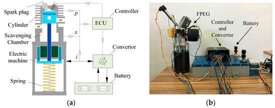
Figure 1.
Configurations of the free-piston engine generator (FPEG), (a) structure, (b) prototype.
The system working cycle is described in Figure 2. In the starting state, the piston assembly was driven by the linear electric machine. After entering stable operation, one complete working cycle of FPEG included two strokes. During the compression stroke, the trapped fuel mixture was compressed by the spring. As the spark plug ignited the fuel mixture at the end of the compression stroke, the chemical energy of fuel was absorbed by the linear electric machine and the spring. During the expansion stroke, the spring extension and the linear electric machine worked as a generator.
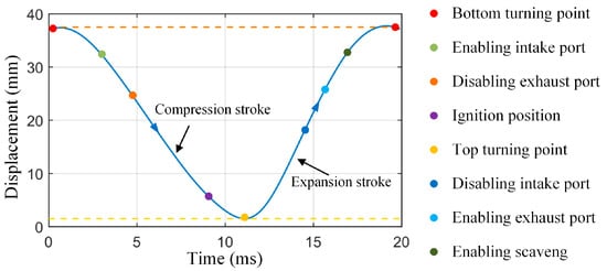
Figure 2.
Two-stroke working cycles of the FPEG.
2.2. Combustion System
Figure 3 shows the combustion system of FPEG, which was a single-cylinder engine. It was equipped with GDI and spark plug, and was fueled by gasoline. The engine used solid graphite self-lubricating bearings for lubrication. Piston displacement was 0 when the piston was at the TTC. Part of the combustion system parameters are shown in Table 1. The compression ratio in Table 1 indicates the in-cylinder compression ratio when the scavenging port was closed.
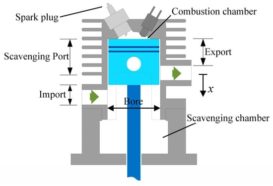
Figure 3.
Structure of the combustion system.

Table 1.
Combustion system of the FPEG.
2.3. Linear Electric Machine
Most FPEGs choose the moving magnet three-phase motor because of high thrust density. But the thrust fluctuation and eddy-current loss are serious. The linear electric machine (LEM) used in this paper is shown in Figure 4. The machine was a moving coil single-phase permanent magnet motor. The LEM worked without current commutation, which helped improve efficiency. The mover of the LEM was connected to the free piston and reciprocated between TTC and BTC. The LEM used in this paper was tested, and the thrust constant is shown in Figure 5.
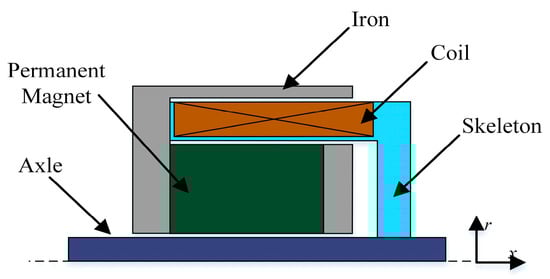
Figure 4.
Structure of the linear electric machine (LEM).
Figure 5.
Thrust constant map of the LEM.
2.4. Power Convertor
An H-bridge circuit was designed to switch the working mode of the linear electric machine and control the current. As shown in Figure 6, the H-bridge consisted of four MOSFETs (metal-oxide-semiconductor field-effect transistor), two diodes, battery, and resistance. The linear electric machine can be operated as a motor or a generator. The power supply can work in battery-charging mode or -discharging mode.
Figure 6.
Power convertor circuit, (a) composition, (b) current flow.
When the linear electric machine was in motoring mode, K1, K3, and K4 turned on, K2 turned off, and the current flow was K1→K3→M→K4. When the linear electric machine was in generating mode, K1, K3, and K4 turned off, K2 turned on, and current flowed through the boost circuit K2 to the battery after free-wheeling diode. The compression stroke current flow was D2→K1→U→D1. The expansion stroke current flow was K3→K1→U→K4. This H-bridge was verified to be able to realize stable operation effectively in simulation analysis.
3. Modeling of FPEG
The piston motion of FPEG was affected by various factors such as combustion process, electromagnetic force, friction force, and spring force.
3.1. Thermodynamic Model
The combustion model described the variation of the heat release rate in the cylinder from the ignition of the spark plug to the beginning of the expansion stroke. In order to describe the combustion process, it was also assumed that: The working fluid in the cylinder was ideal gas, and the pressure, the volume, and the temperature were in accordance with the ideal gas state equation; the engine combustion process used Weber formula to describe variation of its heat; we ignored the ventilation loss of the system. According to the conclusion in [16], the heat released by combustion process can be described as
where 6.908 is the vibe constant, is the heat release of the fuel, is time variable, is lower heating value of the fuel, is the injected fuel mass per cycle, is combustion efficiency, m is combustion quality index, T is the combustion duration, and is start time of combustion.
Due to the difference of combustion process in different cycles, combustion fluctuation was the common characteristic of spark ignition gasoline engine, which was manifested as the change of combustion chamber pressure. For FPEG, the combustion fluctuation was the major disturbance in free-piston motion. Therefore, it was necessary to model the combustion fluctuation. According to [19], it was assumed that: Combustion fluctuation was caused by random fluctuation in injected fuel mass and combustion duration, and random fluctuation was in line with the uniform distribution. The injected fuel mass designed for the prototype was 2.5 mg. According to the error of the injector in the test, a deviation mass of 0.2 mg was added. Combustion duration was also an important parameter affecting combustion. The shorter the combustion duration, the faster the rate of heat release and the better the thermodynamic cycle were of the ICE. The combustion duration of a gasoline engine may be more than 8 ms in cold start; therefore, the combustion duration adopted in this paper was 6–8 ms during stable operation. The fluctuation of injected fuel mass and combustion duration can be expressed Equations (2) and (3). Based on the uniform distribution, the COV (Coefficient of Variation) of IMEP (Indicated Mean Effective Pressure) can be calculated from the cycle fuel injection amount, and the calculation result was about 8%. After adding the fluctuation, the combustion heat release rate fluctuation range is shown in Figure 7.
Figure 7.
Fluctuation of heat release rate.
According to the first law of thermodynamics and the ideal gas state equation, the pressure during compression stroke and expansion stroke can be expressed as
where is cylinder pressure, is adiabatic index of stable operation, is displacement between the free piston and cylinder head, is the velocity of piston, is the equivalent displacement of combustion chamber when the piston is at TTC, and is piston sectional area.
3.2. Scavenging Chamber Pressure Model
The free-piston motion of two-stroke engines was also affected by the scavenging chamber pressure. The pressure change in the scavenging chamber was divided into three stages. The volume change of the scavenging chamber was regarded as adiabatic process. According to the law of thermodynamics, the scavenging chamber pressure can be described as
where is scavenging chamber pressure, is standard atmosphere pressure, is the pressure of gas exchange, is current scavenging chamber volume, is total scavenging chamber volume, is adiabatic index, is the closed position of import, and is the top edge of scavenging port.
3.3. Linear Electric Machine Model
Linear electric machine as the load of FPEG is a key component of electrical energy conversion. According to Lorentz’s law, electromagnetic force can be expressed as
where is electromagnetic force, is thrust constant, and is transient current.
As shown in Equation 7, the electromotive force (EMF) in the armature was proportional to the velocity of the free piston.
where is EMF, and is EMF constant.
Figure 8 describes the equivalent circuit of linear electric machine. When the linear electric machine works in motoring mode, the voltage balance equation can be written as
where is the terminal voltage of linear electric machine, is the inductance of linear electric machine, is the coil current, and is the internal resistance of linear electric machine.
Figure 8.
Equivalent circuit of the LEM.
When the linear electric machine works in generating mode, the dynamic voltage balance equation is described as
where is the external equivalent load of the linear electric machine.
3.4. Friction and Spring Model
The friction force of free piston described as Equation 10 was divided into static friction force and dynamic friction force.
where is friction force, is frictional coefficient, and is static friction.
In addition, the elastic force will also act on free piston. In our research, the spring was a constant-stiffness spring, and the resilience can be expressed as Equation (11).
where is elastic force, is elasticity coefficient, and is the initial length of the mechanical spring.
3.5. Dynamic Model
The free-piston motion was decided by the resultant force acting on the piston. According to Newton’s second law, when the free piston moves from TTC to BTC, the dynamic equation is expressed as Equation (12).
where is the mass of the piston assembly, is the gravity acting on the piston assembly, is the force of in-cylinder gas, and is the force of gas in scavenging chamber. The positive direction was defined to be from TTC to BTC.
4. Controller Design
As a novel power device, FPEG has the advantages of low friction during movement and variable compression ratio, but the limitation of the crankshaft mechanism makes the movement control of the free piston more demanding. It is necessary to avoid instability and misfire due to lack of energy, but also to avoid excess energy so that damage to the engine is avoided. As the core moving part of FPEG, the control of free-piston stable operation can be attributed to a point-to-point (PTP) control problem. There are no specific requirements for the parameters, such as the trajectory and speed during the motion, as long as the turning points of each stroke reach the target.
The designed controller must meet the following requirements: Reliability, stability, and limited servo subroutine time. The control program was executed by a DSP (digital signal processor) with a frequency of 150 MHz The controller executed the program every 0.1 ms and continuously output current to control the movement of the piston. PTP control of the free piston allowed a little undershoot, but the overshoot had strict requirements. In order to prevent the collision between free piston and cylinder head, the overshoot of the TTC was not greater than the reserved installation clearance.
4.1. State Control of the FPEG
The finite-state machine (FSM) is a mathematical model of computation. It is an abstract machine that can be in exactly one of a finite number of states at any given time. The FSM theory was used to establish a model to achieve the states switch. Linear electric machine states and the switching condition are shown in Figure 9.
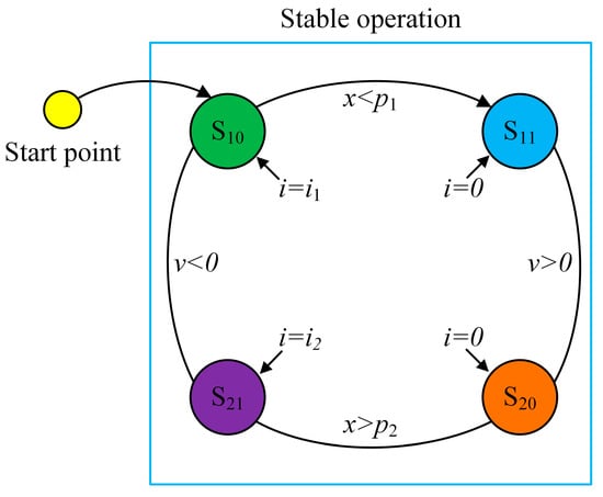
Figure 9.
The finite-state machine (FSM) model for the LEM state switching.
In order to improve the system power density, it was necessary to maximize the piston acceleration and deceleration in motion. The current control strategy can be described as Equation (13).
where is stroke target current, is the current of linear electric machine used in compression stroke, is state switch positon in compression stroke, is the current of linear electric machine used in expansion stroke, and is state switch position in expansion stroke.
According to FSM in Figure 9 and Equation (13), the stable operation of free piston was divided into four working states, which are shown in Figure 10.
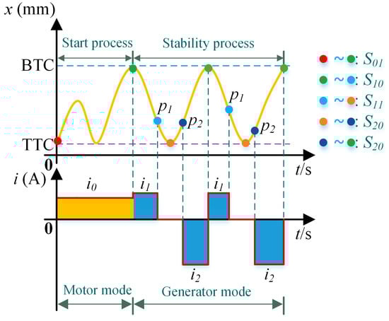
Figure 10.
Working states of the FPEG.
According to the principle of energy conservation, the stable operation energy conservation integral equation is described as:
where is the starting point of compression stroke in stable operation, is the TTC in stable operation, is BTC in stable operation, and is the energy that cannot be established in mathematical model during working cycle, mainly including mechanical friction loss and gas resistance loss.
4.2. Top Turning Center Control Strategy
Iterative learning control (ILC) strategy is applicable to control systems with repetitive motion. In the compression stroke, there is no combustion fluctuation, and the force of free piston is regular. So the TTC can be controlled by ILC control strategy.
The control of TTC prohibited excessive overshoot. When the free piston was at TTC, the value of installation clearance reserved was 0.5 mm. Based on the above factors, the control error of TTC was limited within the range of ±0.3 mm.
The TTC control error of the j-th cycle compression stroke () is:
where is the target TTC of the compression stroke and is the actual TTC of the j-th cycle compression stroke.
According to the ILC control strategy, the j-th cycle compression stroke state switching position () 2qw corrected by the (j − 1)-th cycle compression stroke state switching position ()
where and were the starting points of the compression stroke of the j-th cycle and the (j-1)-th cycle, and were iterative learning coefficients.
4.3. Bottom Turning Center Control Strategy
The situation of BTC was different from TTC. Due to combustion fluctuations, the cylinder pressure in expansion stroke in each cycle was different, which led the force of the piston in each cycle to be different. A new control strategy based on combustion states estimation for the BTC control is presented in this paper.
The piston velocity was 0 at the start and end of the expansion stroke. According to kinetic energy theorem, the work done by external force was 0. Equation (18) describes the energy relationship during combustion process.
where is the electrical energy, is the elastic energy, is the pressure energy of the scavenging chamber, is the combustion energy, and is to describe the energy in cycle combustion fluctuations by establishing a random mathematical model during the work cycle.
A state observer was used to observe the peak pressure of combustion in the cylinder. Based on the peak pressure of combustion, the combustion energy of current cycle was estimated. According to the energy conservation theorem, the expansion stroke state switching position was calculated. The j-th cycle expansion stroke state switching position () can be calculated by Equations (19) and (20).
where is the target BTC of the expansion stroke, is the estimated coefficient of combustion energy, is the peak pressure in cylinder during combustion, is BTC control error of the (j − 1)-th cycle expansion stroke, is the actual BTC of the (j − 1)-th cycle, and and are adjustment coefficients.
4.4. Controller Model
When FPEG started working, the linear electric machine worked in motoring mode, and the free piston was close to BTC. Then the compression stroke started, the fuel was injected into the combustion chamber, and the linear electric machine worked in generating mode. When the free piston reached the state switch position of compression stroke, the linear electric machine stopped working. Once the free piston reached the ignition point, the spark plug ignited the fuel–air mixture, and the high pressure generated by combustion made the piston into expansion stroke. The calculator calculated the state switch position of expansion stroke according to the peak pressure. The target current in each stage was a constant value. The controller model of TTC/BTC is shown in Figure 11, where a is the acceleration of the piston.
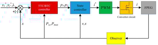
Figure 11.
Top turning center (TTC) control and bottom turning center (BTC) controller model.
5. Simulation and Experiment Research
5.1. Simulation Model
According to the theoretical mode of FPEG in Section 3, the simulation model of FPEG is shown in Figure 12.
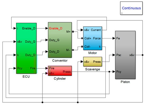
Figure 12.
Simulation model of the FPEG.
The solver chosen for simulation was ode23, the maximum step size was 10-7, and time tolerance was 10*128*eps. The simulation parameters determined by the structure of the prototype are shown in Table 2.
Table 2.
The initial simulation parameters.
5.2. Model Verification
An experiment on FPEG with ignition was completed, and experiment data and simulation data were consistent. The comparison results of displacement and velocity are shown in Figure 13. As can be seen, the compression stroke of this cycle was about 12 ms and the expansion stroke was about 7 ms. The velocity of expansion stroke was faster than compression stroke because of pressure generated by the combustion.
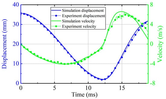
Figure 13.
The piston motion verification (stable operation).
The verification of pressure can be seen in Figure 14. In the cycle shown in Figure 14, the maximum pressure of combustion in cylinder reached about 22 bar. The mixture in the cylinder was judged to be fully burned from the max pressure.
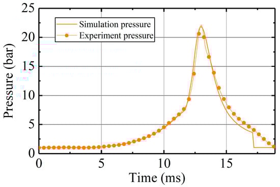
Figure 14.
The in-cylinder pressure verification (stable operation).
The linear electric machine worked as a generator both in compression stroke and combustion stroke during stable operation. The generating current of the cycle is shown in Figure 15, the current was about 25 A in compression stroke, and the current in expansion stroke was about −52 A because the free piston moved to opposed direction.
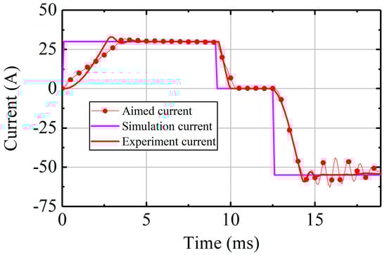
Figure 15.
The current verification (stable operation).
5.3. Simulation Research
5.3.1. In-Cylinder Pressure Analysis
Figure 16 describes the in-cylinder pressure in continuous working cycles. As can be seen, the thermodynamics process changed from cycle to cycle, obviously. The maximum pressure was 19 bar and the minimum pressure was 16 bar. The fluctuation of the peak pressure was the main factor that caused the control error of BTC.
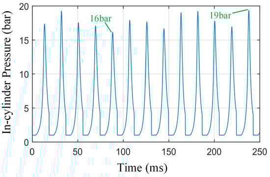
Figure 16.
The in-cylinder pressure during 0.25 s.
5.3.2. Piston Motion Analysis
The velocity and displacement of free piston were simulated when FPEG worked in stable operation. The relationship between the velocity and displacement of the free piston are shown in Figure 17 and Figure 18. The trajectory in Figure 17 was uncontrolled and in Figure 18 was controlled.
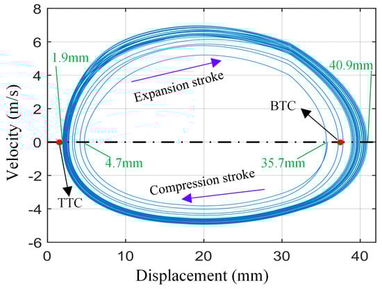
Figure 17.
The velocity vs. the displacement (without control).
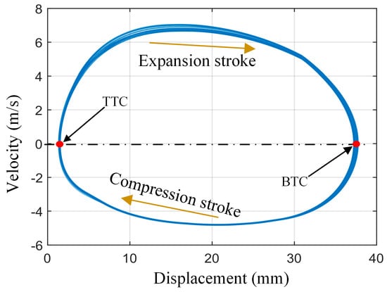
Figure 18.
The velocity vs. the displacement (with control).
The results show that free piston cannot establish a self-stable state without active motion control. The actual position of BTC/TTC was far from the expected position without control. This was because the free-piston movement was susceptible to external force. The cylinder pressure fluctuation interfered with the stable motion of the free piston. It should be noted that in the actual system, the effect of combustion fluctuation on free-piston motion is likely to be more severe than the simulation result because the fluctuations of TTC and BTC will further increase the combustion fluctuation, thus entering a vicious circle. After the active control on the free piston, its motion trajectory was greatly improved and the different compression stroke displacement also achieved good coincidence. Therefore, the active control strategy developed in this paper is necessary and effective for stable operation.
5.3.3. TTC and BTC Analysis
The control objective was the TTC and BTC of free piston in this paper. The coordinates of each point in Figure 19 represent the cycle turning centers, and the Table 3 shows the statistical characteristics and target values of turning centers.
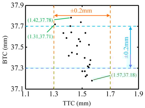
Figure 19.
The vibration of BTC and TTC.
Table 3.
The position of TTC and BTC.
As can be seen from the data, the position of TTC and BTC was in line with the expected setting. The position of TTC was mostly within 0.1 mm from the target value, and its max central deviation and standard deviation were within ideal range. Due to the combustion fluctuation, the position distribution of BTC was slightly dispersed compared with TTC. Most of them were within 0.2 mm from the target value.
5.3.4. State Switch Position Analysis
ILC was used to control TTC. Figure 20 shows the relationship between the state switching position of compression stroke and the TTC error of previous compression stroke. It can be seen that they were positively corrected. This is because when the TTC error of previous compression was larger, the piston had insufficient stroke, and the linear electric machine needed to decelerate into generating mode. So the state switching position of compression stroke was larger, too.
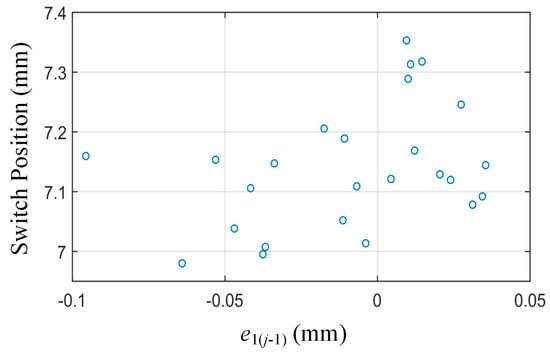
Figure 20.
The compression stroke switch position.
Because of the combustion disturbances in the expansion stroke, the free piston was most affected during this stroke. Figure 21 shows that the state switching position of expansion varied with the peak pressure. As can be seen, they were negatively correlated. This is because the higher peak pressure meant the greater combustion energy in current cycle. The linear electric machine needed to switch to generating mode as soon as possible. So the state switching position of expansion stroke should be in advance.
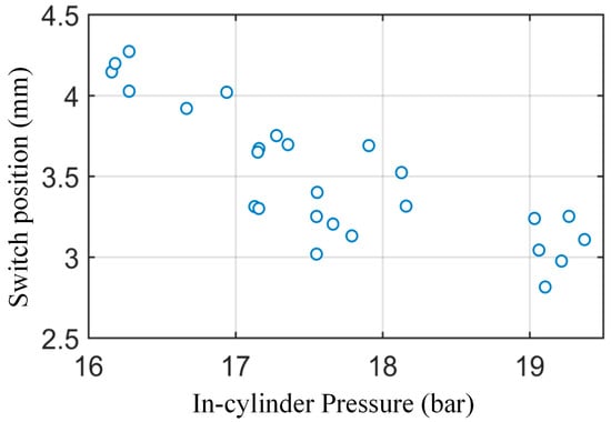
Figure 21.
The expansion stroke switch position.
5.4. Experiment Research
5.4.1. Control Based on Fixed Generated Energy
The fixed generated energy during expansion stroke was set for each cycle, and the experiment results are shown below.
Figure 22 shows that the generating current in expansion stroke of the three cycles was all about -60A, and the generated energy during expansion stroke was almost the same. However, the free piston had different trajectories and BTCs per cycle.
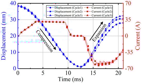
Figure 22.
The tested piston motion (fixed generated energy).
Figure 23 shows the pressure of three cycles. It is obvious that the combustion was different for each cycle, and it can be inferred that the energy generated by cycle 1 combustion was minimal. Therefore, when the generated energy was fixed, the BTC of cycle 1 was the largest deviation among the three cycles.
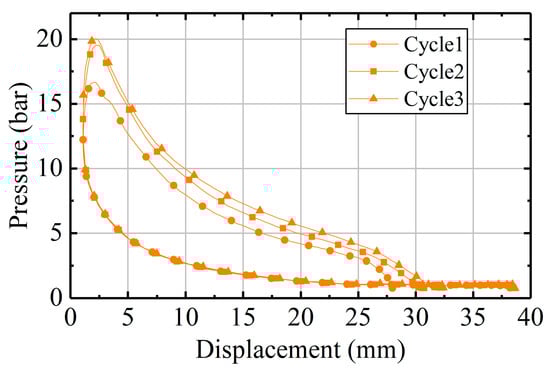
Figure 23.
The tested in-cylinder pressure (fixed generated energy).
It can be concluded from the experiment that the fixed power generation cannot be used to control FPEG due to the random fluctuation of combustion.
5.4.2. Control Based on Peak Pressure Feedback
In-cylinder pressure is one of the important parameters for evaluating combustion. A control strategy was proposed to adjust the generated energy of expansion stroke according to the peak in-cylinder pressure.
It can be seen from the Figure 24 that the control strategy using peak in-cylinder pressure as feedback still failed to achieve good control effect. The two cycles were controlled by peak pressure, and the controller calculated the generated energy of expansion stroke according to the peak pressure generated by combustion. The experiment results show that this control strategy is still not suitable for controlling FPEG, and the Figure 25 illustrates why.
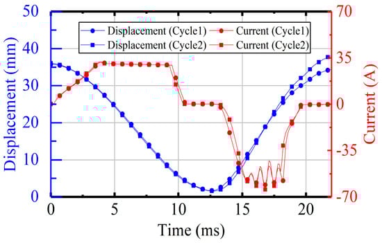
Figure 24.
The tested piston motion controlled by peak pressure.
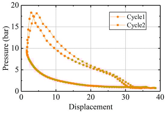
Figure 25.
The tested in-cylinder pressure controlled by peak pressure.
The peak pressure of the cycle 1 and cycle 2 was almost the same, so the generated energy of the expansion stroke calculated by control strategy was almost the same. However, it is clearly seen from Figure 25 that the energy generated by cycle 2 combustion was greater than the energy produced by cycle 1 combustion.
As can be seen from the experiment mentioned above, the challenge in BTC control is the combustion fluctuations. Neither the fuel mass nor peak in-cylinder pressure can accurately represent the combustion of the current cycle.
5.4.3. Tested Performance of the Prototype System
Based on the tested P-V (pressure- volume) maps shown in Figure 23, the main performance of the system was analyzed and is shown in Table 4. The indicated power of the prototype was about 1.5 kW, the indicated thermal efficiency was about 37.6%, and the total generation efficiency of the system was about 32.3%.
Table 4.
The tested performance of the prototype system.
6. Conclusions
In this paper, based on theoretical calculations and dynamic analysis, a single-cylinder two-stroke FPEG prototype was designed, and a simulation model including combustion fluctuations was established in Matlab/Simulink. The accuracy of the simulation model was verified by test.
A reciprocating motion control strategy of free piston to enable the stable running of the system was proposed, including TTC controller based on ILC and BTC controller based on in-cylinder combustion energy estimation. The TTC control strategy can obtain the power generation current of the next cycle compression stroke according to the piston movement state of the current cycle compression stroke. After repeated learning, the TTC was finally stabilized at the target position. The BTC control strategy can predict the cycle combustion energy release from the peak in-cylinder pressure for each cycle, thereby determining the current generated during the expansion stroke of the cycle, and achieving stable control of the BTC.
The simulation results show that, compared with the piston trajectory without active motion control, the piston trajectory with active motion control had a good coincidence in the presence of combustion fluctuations. The position of the TTC was effectively controlled, which can prevent collision between the cylinder head and the free piston, which is beneficial to the prototype test.
The test results show that the free piston of FPEG can achieve stable reciprocating motion, but the BTC position of the free piston still had a certain deviation due to the complexity of combustion fluctuations. Combustion fluctuations are not only reflected in the difference in peak pressure of the expansion stroke, but also in the shift of the peak pressure phase. In future tests, more advanced combustion monitors and controllers will be designed to ensure that the BTC position of the free piston can be effectively controlled.
Author Contributions
H.Y. completed most of the theoretical derivations and finished this manuscript; Z.X. provided technical guidance and opinions on the work; J.L. completed the test research and revised the paper; D.L. designed the controller and participated in simulation research; X.J. revised the paper. All authors have read and agreed to the published version of the manuscript.
Funding
This work is supported by National Natural Science Foundation of China (NO. 51875290, 51975297).
Conflicts of Interest
The authors declare no conflict of interest.
References
- Jia, B.; Smallbone, A.; Feng, H.; Tian, G.; Zuo, Z.; Roskilly, A.P. A fast response free-piston engine generator numerical model for control applications. Appl. Energy 2016, 162, 321–329. [Google Scholar] [CrossRef]
- Blarigan, P.V. Advanced internal combustion electrical generator. In Proceedings of the 2002 US DOE Hydrogen Program Review, Livermore, CA, USA, 9–11 May 2002. [Google Scholar]
- Jia, B.; Zuo, Z.; Tian, G.; Feng, H.; Roskilly, A.P. Development and validation of a freepiston engine generator numerical model. Energy Convers. Manag. 2015, 91, 333–341. [Google Scholar] [CrossRef]
- Woo, Y.; Lee, Y.J. Free piston engine generator: Technology review and an experimental evaluation with hydrogen fuel. Int. J. Automot. Technol. 2014, 15, 229–235. [Google Scholar] [CrossRef]
- Pulkrabek, W.W. Engineering Fundamentals of the Internal Combustion Engine, 2nd Ed. J. Eng. Gas Turbines Power 2004, 126, 198. [Google Scholar] [CrossRef]
- Mikalsen, R.; Roskilly, A.P. The control of a free-piston engine generator. Part 1: Fundamental analyses. Appl. Energy 2009, 87, 1273–1280. [Google Scholar] [CrossRef]
- Jia, B.; Zuo, Z.; Feng, H.; Tian, G.; Smallbone, A.; Roskilly, A.P. Effect of closed-loop controlled resonance based mechanism to start free piston engine generator: Simulation and test results. Appl. Energy 2016, 164, 532–539. [Google Scholar] [CrossRef]
- Mikalsen, R.; Roskilly, A.P. The design and simulation of a two-stroke free-piston compression ignition engine for electrical power generation. Appl. Therm. Eng. 2008, 28, 589–600. [Google Scholar] [CrossRef]
- Jia, B.; Zuo, Z.; Feng, H.; Tian, G.; Roskilly, A.P. Investigation of the starting process of free-piston engine generator by mechanical resonance. Energy Procedia 2014, 61, 572–577. [Google Scholar] [CrossRef]
- Mikalsen, R.; Jones, E.; Roskilly, A.P. Predictive piston motion control in a free-piston internal combustion engine. Appl. Energy 2010, 87, 1722–1728. [Google Scholar] [CrossRef]
- Mikalsen, R.; Roskilly, A.P. The control of a free-piston engine generator. Part 2: Engine dynamics and piston motion control. Appl. Energy 2010, 87, 1281–1287. [Google Scholar] [CrossRef]
- Němeček, P.; Vysoký, O. Control of two-stroke free-piston generator. In Proceedings of the 6th Asian Control Conference, Bali, Indonesia, 18–21 July 2006. [Google Scholar]
- Goto, S.; Moriya, K.; Kosaka, H.; Akita, T.; Hotta, Y.; Umeno, T.; Nakakita, K. Development of free piston engine linear generator system. Part 2—Investigation of control system for generator. SAE Tech. Pap. 2014, 1, 247–254. [Google Scholar]
- Kosaka, H.; Akita, T.; Moriya, K.; Goto, S.; Hotta, Y.; Umeno, T.; Nakakita, K. Development of free piston engine linear generator system. Part 1—Investigation of fundamental characteristics. SAE Tech. Pap. 2014, 1, 882–888. [Google Scholar]
- Xu, Z.; Chang, S. Improved moving coil electric machine for internal combustion linear generator. IEEE Trans. Energy Convers. 2010, 25, 281–286. [Google Scholar]
- Xu, Z.; Chang, S. Prototype testing and analysis of a novel internal combustion linear generator integrated power system. Appl. Energy 2010, 87, 1342–1348. [Google Scholar] [CrossRef]
- Lin, J.; Chang, S. Modeling and simulation of a novel internal combustion-linear generator integrated power system using matlab/simulink. In Proceedings of the IEEE International Conference on Power and Energy, Kota Kinabalu, Malaysia, 2–5 December 2012. [Google Scholar]
- Xu, Z.; Chang, S. Hierarchical hybrid control of a four-stroke free-piston engine for electrical power generation. In Proceedings of the International Conference on Mechatronics and Automation, Changchun, China, 9–12 August 2009. [Google Scholar]
- Lin, J.; Xu, Z.; Chang, S.; Yin, N.; Yan, H. Thermodynamic simulation and prototype testing of a four-stroke free-piston engine. J. Eng. Gas Turbines Power 2014, 136, 051505. [Google Scholar] [CrossRef]


© 2020 by the authors. Licensee MDPI, Basel, Switzerland. This article is an open access article distributed under the terms and conditions of the Creative Commons Attribution (CC BY) license (http://creativecommons.org/licenses/by/4.0/).