Abstract
In DC microgrids, distributed energy storage plays a key role in stabilizing the DC bus voltage. The bidirectional DC/DC converter in the distributed energy storage system should be designed according to the voltage level and electromagnetic isolation requirements, and multiple energy storage units should be coordinated for load current distribution according to the state of charge (SOC). This paper proposes a SOC power index droop control strategy by communication lines to coordinate the fast and high-precision distribution of load current among multiple energy storage units, and the SOC between energy storage units quickly converges to a consistent state. Considering that communication lines are susceptible to interference, this paper further proposes an improved SOC power index droop control to overcome the effects of communication line failures. Considering the high cost of the energy storage unit, it should be connected to the DC microgrid in layers to achieve a reasonable allocation of resources in practical applications. In order to provide high-quality power to a large power grid, the quantification standards of the DC bus fluctuation range and the working range of each converter are further discussed to maximize the stability of the DC bus voltage and grid-connected power fluctuation.
1. Introduction
Distributed energy storage is the key issue to solve the issue of grid-connected renewable energy generation. For example, it can improve the ability of the grid to accept wind and photovoltaic (PV) power [1,2,3]. A typical DC microgrid structure is mainly composed of a distributed generation unit, an energy storage unit, a load cell, and a grid-connected converter [4,5,6], as shown in Figure 1. DC microgrid research focuses on stabilizing the DC bus voltage to ensure the power balance of the system. To stabilize bus voltage fluctuations and solve energy supply volatility issues, adding energy storage devices can improve the device’s voltage sag and the inrush issues caused by load-switching, changes in natural conditions, and instantaneous faults in DC microgrid systems; this improves the reliability and scheduling flexibility of the distributed generation grid connection. Using low bandwidth communication control reduces the long-distance stability and DC microgrid distribution of the system due to network delay packet loss and other issues. To avoid the risk caused by long-distance communication control, each unit is divided into three control layers according to the normalized voltage of DC bus and coordinated control of various units [7]. Compared with the two-level converter, the three-level converter has only half of the switches to change state peer cycle, and the voltage stress on the switch is only half of the bus voltage [8,9].
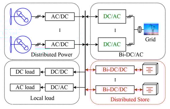
Figure 1.
Typical configuration of a DC microgrid.
As a key device connecting the energy storage unit and the DC bus, the bidirectional DC/DC converter requires a high-voltage and high-power bidirectional DC/DC converter topology. However, the traditional two-level bidirectional DC/DC converter topology is not suitable for high-voltage and high-power applications, requires a multi-level topology, and has the characteristics of simple structure, high efficiency, reliability, and easy modular expansion. The three-level bidirectional DC/DC converters suitable for accessing the DC microgrid are mainly isolated [10,11,12,13] and non-isolated [14,15,16]. For energy storage side modular bidirectional DC/DC converter, when using input parallel, output parallel (IPOP), the current sharing issue between modules needs to be considered; when using input series, output series (ISOS), the voltage equalization issue needs to be considered; when using input parallel, output series (IPOS) or input side series connection, output side parallel (ISOP), both current sharing and voltage equalization issues need to be considered [17,18].
The DC voltage represents the state of power balance. When the renewable energy generation is greater than the load demand, the DC line-of-sight voltage rises. When the renewable energy generation is less than the load demand, the DC line-of-sight voltage decreases. The energy storage medium is inconsistent with the state of charge (SOC) of the energy storage unit due to the process and external environmental factors and exhibits randomness. Considering the randomness and slow change of the state of charge of the energy storage unit in the distributed energy storage system, an improved SOC power exponential control strategy is adopted in the charging and discharging process of the energy storage unit to find the optimal droop curve to make the system fast [19,20,21,22,23,24,25] and then converge to equilibrium. When distributed energy storage is suitable for low-bandwidth communication, SOC power exponential droop control should be adopted to achieve fast and accurate distribution of load current. In the case of communication failure or unsuitable conditions for communication, switch to emergency state to continue operation.
If the energy storage system is connected to the DC microgrid to participate in the constant regulation of the bus voltage, the energy storage unit quickly reaches the maximum allowable number of charge-discharge cycles and shortens the service life. It is necessary to quantify and analyze the best solution through voltage fluctuation level and power fluctuation level quantification and compensation scheme, to achieve the lowest voltage fluctuation and power fluctuation in the DC microgrid, and to provide high quality electric energy for a large grid [26,27,28,29]. Pre-adjusting the SOC to the optimal state during the first layer control is to prepare for the full play of the second-layer control function of the energy storage unit.
2. Three-Level Bidirectional DC/DC Converter
The bidirectional DC/DC converter is used as an interface between the energy storage units and the DC bus and needs to meet the requirement that the energy can flow in both directions. If the renewable energy generation is higher than the energy required of the system, the excess energy is charged to the energy storage unit by the bidirectional DC/DC converter. Once the generated energy is insufficient, the energy storage provide energy to the system and maintain the power balance of the system. The bidirectional DC/DC converters can be divided into two types: isolated and non-isolated converters.
2.1. Isolated Three-Level Biditioanl DC/DC Converter (TL-BDC)
Compared with the two-level converter, the three-level converter operates only half of the switches in one cycle, which can effectively reduce the voltage stress of the switch [8,9]. The main functions of the high-frequency transformer are (1) to achieve electrical isolation of the DC bus and energy storage components, to reduce electromagnetic interference (EMI); (2) to adjust the voltage conversion level; (3) to adjust transformer leakage inductance and switches’ parasitic capacitance resonance, so with IGBT/MOSFET it is easier to achieve soft switching then improve converter efficiency. The isolated three-level bidirectional DC/DC topology modulation is divided into fixed-frequency pulse width modulation (PWM) mode and frequency modulation (PFM) mode. The variable frequency modulation increases the design difficulty of the magnetic component, the driving circuit, and the filtering circuit, and the gain is greatly affected by the load when the switching frequency deviates from the resonant frequency. Fixed-frequency PWM modulation simplifies the design of the resonant parameters. When the switching frequency is equal to the resonant frequency, the gain is not affected by the load. Achieving soft switching requires sufficient switching current and dead time, but the dead time is too large to increase voltage and current fluctuations, and the dead time needs to be limited to a reasonable range.
The topology of a series of isolated three-level bidirectional DC/DC converters (TL-BDCs) is shown in Figure 2. In [10], the high-voltage side MOSFETs adopt pulse width and amplitude modulation, and the resonant tank voltage amplitudes [−V1, V1], [−0.5V1, V1], [−0.5V1, 0.5V1], are respectively modulated, as shown in Figure 2a. High gain mode, medium gain mode, and low gain mode are used to meet the requirements of wide range input of energy storage component voltage. In the forward power transmission, the high-voltage side circuit adopts three-level modulation, and the low-voltage side circuit is in an uncontrolled rectification state. When the reverse power is transmitted, the high-voltage side circuit adopts three-level modulation, and the low-voltage side circuit is in a fixed-frequency modulation state. When the topology is pulse width and amplitude modulation (PWAM), some MOSFETs can implement zero voltage switching (ZVS) or zero current switching (ZCS). In [11], the high-voltage side MOSFETs form a three-level structure, and the low-voltage side MOSFETs adopt a buck/boost circuit parallel structure, as shown in Figure 2b. In the traditional pulse width phase shift modulation (PPS), the transformer leakage current control is added, and the peak current and voltage and loss are reduced. All MOSFETs implement ZVS switches. Due to the Direct Current Slew Rate (DCSR) control technology, the transformer loss is significantly reduced, and the overall efficiency is improved. When running in the opposite direction, the three-level half-bridge works in the inverting state. After passing through the transformer, the energy is passed through the two half-bridge circuits with the help of the support capacitor Vc to achieve buck operation. In [12], the phase shift control is adopted in the double active bridge (DAB) with capacitor inductance series resonance (CLLC), as shown in Figure 2c. In bidirectional operation, the active bridge works in the inverter state, and the passive bridge works in the rectified state. Some MOSFETs can realize the ZVS switch and analyze the phase conditions required to realize the ZVS switch. In [13], the bus capacitor voltage equalization control is added on the basis of the three-level DAB circuit, and the parameter design and control scheme are optimized, as shown in Figure 2d.
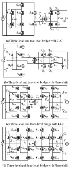
Figure 2.
Isolated three-level bidirectional DC/DC converter (TL-BDC).
A common feature of isolated TL-BDCs to achieve zero voltage turn-on is shown in Figure 3. Before the driving voltage Ugs arrives, the switch is turned on, that is, Uds has dropped to 0. The essence is that before the switching signal arrives, the current flows through the diode ids < 0, which releases the charge of the parasitic capacitance between drain and source (DS), realizes ZVS-ON. The parasitic parameters of the switches, the leakage inductance on both sides of the transformer, the resonance parameters, the inconsistent printed circuit board (PCB), and the resonant frequency of the circuit deviates from the design frequency. Therefore, the topology and the modulation strategy are required to have certain redundancy to the actual parameters of the circuit. The phenomenon of sampling data loss and modulation wave loss often occurs during the actual operation of the circuit. Therefore, the control algorithm also needs to have certain fault tolerance. Since the isolated converter uses a transformer, the switching frequency usually operates in a high frequency switching state in order to ensure a high energy density of the converter. When the converter is in light load or heavy load state, it is easy to lose the advantage of soft switch, resulting in the switches being in a hard switch state, and the power loss is serious. It is necessary to monitor the temperature of the switches in real time to provide temperature protection measures for the circuit.
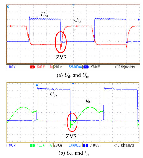
Figure 3.
Features of MOSFET to achieve zero voltage turn-on. ZVS, zero voltage switching.
2.2. Non-Isolated TL-BDC
A group of non-isolated TL-BDCs is shown in Figure 4. Reference [14] uses a DC bus capacitor to provide a three-level state (buck/boost synchronous PWM modulation). The dv/dt and the current spike can be reduced by soft switching. In forward power mode, S2, S3, and S4 can realize ZVS turn-on; when reverse power flows, S1 can realize ZVS turn-on. When the integrated capacitive buck/boost converter is integrated with a switched capacitor network and a buck/boost circuit, the voltage gain is 2/D; when the buck/boost circuit is integrated with n-1 switched capacitor networks, the voltage gain is up to n/D. When the converter is running at high gain, the S1 is subjected to large current stress, which exacerbates switching losses. So, it is suitable for low-voltage, low-power energy storage and photovoltaic systems.
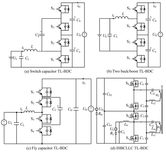
Figure 4.
Non-isolated TL-BDC. IHBCLLC, integrated half bridge capacitor inductance series resonance.
In [15], a two-level buck/boost converter is cascaded to form a three-level bidirectional DC/DC converter. Interleaved PWM modulation is used. S1 and S2 are complementarily turned on, S3 and S4 are complementarily turned on, S2 and S3 are interleaved 180° turned on, S1 and S4 are interlaced 180° turned on, and switches can realize ZVS turn-on. There are three kinds of switching modes when the duty ratio is D < 0.5, three kinds of switching modes when D > 0.5, and only two kinds of switching modes when D = 0.5 (S1 and S4 turn on or S2 and S3 turn on). According to the volt-second balance principle, the converter voltage boost is 1/D, and the voltage stress of the switches in each mode is 1/2 of the high voltage side. However, the modulation method easily causes the duty ratios of the upper and lower half bridges to be inconsistent, thereby affecting the voltage equalization effect of the DC bus and requires an additional voltage equalization control loop at boost mode, which increases the complexity of the control structure.
Reference [16] uses three-level PWM modulation, switches S1 and S4 are complementary turned on, S2 and S3 are complementary turned on, S3 and S4 are interleaved 180° turned on. There are three switching modes when the duty ratio D < 0.5, and three kinds when D > 0.5 at the boost/buck mode and the dv/dt of the switch is small. When the duty ratio D = 0.5, there are only two switching modes (S1 and S3 are on or S2 and S4 are on). According to the volt-second balance principle, the converter voltage gain 1/D is derived. Although the converter proposed in [16] does not have the high voltage gain characteristics of the converter proposed in [14], the voltage and current stress are relatively uniform, and the flying capacitor voltage is easily stabilized to 1/2 of the high voltage side. The flying capacitor three-level DC/DC is easy to expand into a multi-level bidirectional DC/DC converter by increasing the flying capacitor network, further reducing the voltage stress of the switches. So, it is suitable for higher voltage levels. In [3], the integrated half bridge CLLC (IHBCLLC TL-BDC) can achieve of soft switching by fixed frequency PWM.
In Figure 5, the switched capacitor type converter realizes high voltage gain by adding a switched capacitor network. When the voltage variation range is wide, some switching tubes can realize ZVS turn-on, however, S1 has a large current stress. In Figure 6, the flying-capacitor converter is adapted to higher voltage level applications by adding a flying capacitor network. The symmetrical structure and modulation strategy of the topology make the voltage and current stress of the switches relatively average, and it is easy to expand to multi-level bidirectional DC/DC converter. Compared with the isolated three-level bidirectional DC/DC converter, the non-isolated type has no high-frequency transformer isolation, and the dynamic response speed is faster when the power flow direction is switching. When the isolated converter is connected to the DC bus, the circuit is mostly in resonance. The working state, charging mode, and discharging mode switching have a certain time delay. Due to the constraints of power electronics, the three-level bidirectional DC/DC converter cannot be operated independently in high-voltage and high-power applications, and further modular operation is required.
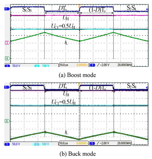
Figure 5.
Experimental verification of the switch capacitor TL-BDC.
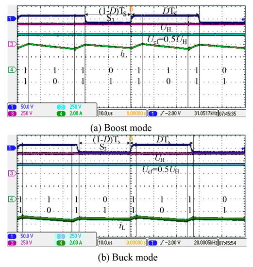
Figure 6.
Experimental verification of the fly capacitor TL-BDC.
Due to the low voltage level of the lithium battery side, the current is large at the rated power, and the modules need to be used in parallel; the voltage level is high on the DC bus side and the modules need to be used in series. When the low-voltage side is connected in parallel, the difference in impedance between modules is easy to cause the current sharing issue; when the high-voltage side is connected in series, there is an issue of inconsistent output voltage caused by factors such as modulation strategy between modules, and a corresponding control strategy is needed to solve the issue. In addition, high-voltage DC bus transmission requires a bidirectional DC/DC converter with a larger power class and voltage level. Two sets of multi-level modulation converters (MMCs) are connected through a high-frequency transformer to a DC bus more than 10 times voltage.
In Figure 7, the integrated CLLC converter can achieve high voltage gain by increasing the CLLC resonant network. Figure 7a–d are a set of tests when the voltage and load are dynamically changed during bidirectional operation, and Figure 7e–f are partial details of the bureau during bidirectional operation. The states of ZVS and ZCS can be observed. For applications with wide voltage variation range, some switches can realize ZVS and ZCS turn-on, and S1 has high current stress.
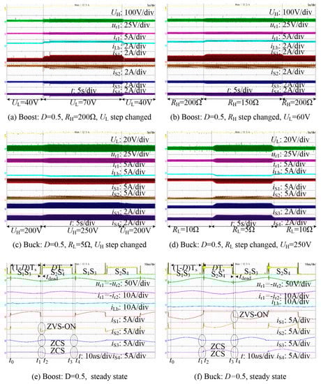
Figure 7.
Experimental verification of the IHBCLLC TL-BDC.
In [18], the master-slave modulation strategy is adopted between parallel modules to reduce the influence of current difference between modules and improve efficiency. However, once the master module has a malfunction, the slave will stop working. The comparison of TL-BDCs topology is shown in Table 1.

Table 1.
Comparison of TL-BDCs.
3. Distributed SOC Droop Control
Distributed droop control with low bandwidth communication has high reliability, high redundancy, and meets the demand of distributed generation. Therefore, it has been widely used and tested in recent years [19]. In [20], authors use voltage droop control to obtain the current reference value of each converter based on the reference power divided by voltage, thus achieving power allocation between converters. Average current control is added to the droop control to realize the average load distribution [21]. In [22], the authors consider voltage fluctuations and power-sharing while a converter is removed in the system. Papers [23,24,25] propose droop control power by state of charge (SOC) distribution; thus relating the droop coefficient with the storage module SOC. When discharging the droop coefficient mp, it is proportional to 1/socn. When charging the droop coefficient mp, it is proportional to socn; thus, the larger n, the higher the SOC equilibrium velocity and the lower the average precision. In [26], the equivalent capacity storage unit adopts a two-layer control strategy. The energy storage unit of SOC tends to average Asoc at discharging mode. The droop coefficient kd is proportional to exp[-p(soc-Asoc)] at charging mode, the droop coefficient kd is proportional to exp[p(soc-Asoc)]. Therefore, as p increases, the average speed will increase, and the accuracy of equalization will reduce. Consequently, the estimation accuracy of SOC will impact the accuracy of load distribution. The energy storage unit is mainly connected to the DC microgrid during the control of the second layer. The energy storage unit allocates the output power rationally, according to the SOC information, so that the energy storage unit can reach a consistent state rapidly and accurately. Due to the adoption of low bandwidth communication control, the communication failure conditions must be considered as that will affect the system stability.
To solve the SOC equilibrium speed and the accuracy of the energy storage unit, we propose to improve the SOC power exponential droop coefficient. The method can transmit the load quickly by only transmitting the SOC and udc. Without the impedance information of the line, the output voltage can be stabilized by restoring the average output voltage of the port. Experimental results show that the proposed SOC power exponential droop control can improve the SOC balancing speed and accuracy of the energy storage unit.
Distributed storage systems require an energy storage unit with a high SOC to emit more power when discharging, but to have less power absorption when charging. This can be realized by fast equalization of the SOC and has no effect on the stability of the system; thus, it can take the effect of line impedance because the SOC information is realized by indefinite integration and the rate of change is low. Thus, the response coefficient is not sensitive enough according to the SOC coefficient, which affects the equipartition effect. In this paper, an improved SOC power exponent droop is proposed to improve the SOC resolution, and the steady DC link voltage is stabilized by the SOC power exponential droop control, so that the system converges to the SOC equilibrium state quickly.
where, .
Droop control can cause a drop in the DC bus voltage, so we should select a normal droop coefficient in a suitable range of the DC bus voltage drop. When the virtual droop coefficient R(soc) is large enough and satisfies requirement (2), the line impedance can be ignored. Equation (1) shows that socn tends to the average value of Asocn and R(soc) is equal to kD; thus, to overcome the line impedance, the kD>r condition needs to be satisfied. While the energy storage unit is charging, idc< 0, the SOC is above its average value, R(soc) > kD, and the energy storage units absorb less electricity. When the SOC is below the average value, R(soc) < kD and the energy storage units absorb more electricity. When the energy storage unit discharges, idc > 0, the SOC is above the average value, R(soc) < kD, and the energy storage units absorb less electricity. When the SOC under the average value, R(soc) > kD and the energy storage units absorb more electricity. In the whole process of charge and discharge, it meets R(soc) + RLoad >> r and should overcome the line impedance effect of r in terms of the load distribution. The parameters of R(soc) have great influence on the droop coefficient, which is shown in Figure 8.
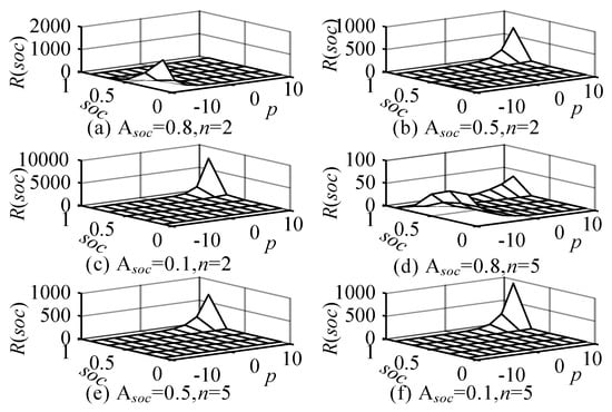
Figure 8.
kD = 2.5, soc = 0.1~0.95, p = −10~10, mesh of R(soc).
Figure 8 shows that the R(soc) surface is relatively flat, which is conducive to the design parameters. If socn is different exactly from average Asocn, mainly affected by p and n. The output current differences Δidc and the remaining battery difference Δsoc have a relation:
The change curve of the output current difference Δidc(Δsoc) can be obtained by Equation (2). The n is fixed, the larger the p is, the faster the output current difference changes. However, when Δsoc approaches 0, the current’s difference is not obvious; thus, the output current’s regulation is weak, which will affect the equilibrium rate of the SOC and needs to regulate R(soc) with n fit. The output current difference Δidc can be adjusted quickly in the whole range of SOC change. At the same time, considering the actual use of the lithium iron phosphate battery, the probability of Δsoc > 0.5 is low when |Δsoc| is close to 1. The output current difference of convergence is a constant when |Δsoc| = 0, idc tends to 0, and the variation curve of the output current difference Δidc is relatively flat.
The energy storage medium of the distributed energy storage system is a lithium battery, which has the characteristics of high density and high energy density, and thus has a long charge-discharge cycle. In order to study the SOC equalization speed, precision, and voltage drop of the DC bus with the change of parameters in distributed droop control, lithium battery capacity 0.5 Ah, rated voltage 200 V, and charge-discharge cycle 20 C were set. MATLAB/Simulink comparative analysis of SOC droop control and bus voltage secondary regulation was done to find a suitable strategy for distributed energy storage control in the DC microgrid. The system structure consisting of two energy storage units, load, and adjustable power supply is shown in Figure 9.
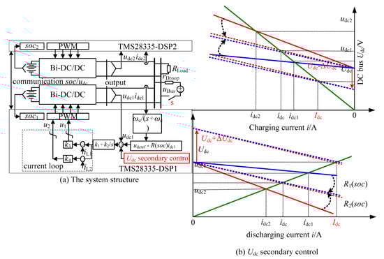
Figure 9.
The diagram of distributed energy storage systems.
Simulation results of the effect of droop on parameter changes are shown in Figure 10. Figure 10a–d include Asocn, which indicates that the SOC power exponential droop control needs to be created by low bandwidth communications. When n = 1, the average load current sharing rate is slower (Δidcmax = 5.2 A), and the SOC convergence accuracy is lower (Δsoc = 2 ~ 5% at 100 s). When n = 2, the load current sharing rate is faster (Δidcmax = 8 A), and the SOC convergence precision is high (Δsoc = 2% at 70 s and Δsoc = 1% at 100 s). Increasing kD increases the SOC equalization but also increases the DC bus voltage drop.
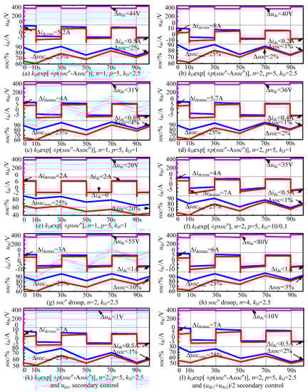
Figure 10.
The result of state of charge (SOC) droop control by MATLAB/Simulink. The first and second lithium battery pack capacity 0.5 Ah, linear zone capacity 0.4 Ah, non-linear zone capacity 0.1 Ah, linear zone rated voltage 200 V, full capacity voltage 220 V, rated current 10 A (20 C). The DC bus voltage 400 V, rated power 5 kW, RLoad = 30 Ω, adjustable power supply uBus = 450 V, and rDroop = 2 Ω series, cyclical access to the DC bus to simulate the new energy output power changes.
Figure 10e–f, excluding the Asocn terms, suggests a communication loss. After the communication is lost, Figure 10e kD remains the same. When discharging, the R(soc) is very small, and it is too weak to adjust the load of the current. When charging, R(soc) is larger (beyond the allowable range) and turns into the traditional U-I droop control. After the communication is lost, Figure 10f kD is changed according to the charge-discharge mode (kD = 10 at discharging and kD = 0.1 at charging). The systems can still work stably, however, the SOC equilibrating time is longer and the accuracy is lower. As seen in Figure 10g–h, the SOC equalization accuracy and speed can be adjusted by n. However, the SOC equalization accuracy and speed are lower than Figure 10a–d and the DC bus voltage drops further. Droop control leads to voltage drops at the access point, reducing the DC bus voltage quality. To realize rapid and accurate distribution of the load current and compensate a bus voltage drop at the same time, the DC bus voltage is adjusted for a second time and the output characteristic curve is translated to achieve the rated value to enhance the stability of the bus voltage. If the upcc is used as the feedback value at the common point, the DC bus voltage deviation is within 1 V, as shown in Figure 10k.
If the average value of the outlet voltage of the energy storage converter (udc1 + udc2)/2 is used as the feedback value, the DC bus voltage deviation is within 10 V, as shown in Figure 10l. The bus voltage secondary control is added based on the droop control of the SOC power exponent. As the discharge-current of the energy storage unit increases, the charging current of the energy storage unit decreases, which has little effect on the SOC convergence accuracy or the load current distribution accuracy. Comprehensive analysis of Figure 10k in the fast and accurate distribution of load current DC bus voltage shows that the deviation is smaller; once the communication line fails, it automatically switches to Figure 10f mode to continue running. Simulation analysis can achieve the design requirements, but also needs further experimental verification.
The experimental comparison verification of SOC droop control is shown in Figure 11. The socn droop control experiment is shown in Figure 11a–b. The droop rate is faster at the start time and the voltage shift is larger, which is consistent with the simulation Figure 10h. The disadvantage is that when soc approaches 0, the voltage drops by a larger amount. The exp[p (socn-Asocn)] droop control experiment is shown in Figure 11c–d, SOC can quickly and effectively adjust the load current distribution in the [0 1] interval and the voltage offset is small, which is convenient for the DC bus voltage secondary recovery control.
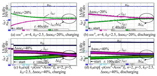
Figure 11.
Experimental verification of SOC droop control.
4. Hierarchical Coordinated Control Strategy
Considering the high cost of the energy storage unit, it should be connected to the DC microgrid in layers to achieve a reasonable allocation of resources in practical applications. In order to provide high-quality power to the large power grid, the quantification standards of the DC bus fluctuation range and the working range of each converter are further discussed to maximize the stability of the DC bus voltage and grid-connected power fluctuation. The hierarchical coordination control structure of the DC microgrid is shown in Figure 12 and Figure 13. In the first layer, the bus voltage is controlled by the grid-connected inverter, and the grid-connected inverter is equivalent to a resistive load. In the second layer, the energy storage unit stabilizes the bus voltage, and the grid-connected inverter is equivalent to a constant power load. The DC bus voltage fluctuation is positively correlated with power variation.
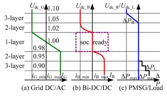
Figure 12.
Hierarchical coordinated control strategy.
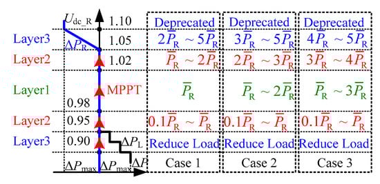
Figure 13.
Hierarchical coordinated control strategy.
In Figure 12, the first layer |ΔUdc| ≤ 0.02, corresponds to the network-free mode, the second layer 0.02 <| ΔUdc | ≤ 0.05 corresponds to the network current limiting mode, and the third layer 0.05 <| ΔUdc | ≤ 0.1 corresponds to the current limiting or islanding mode. The first layer bus voltage | ΔUdc | ≤ 0.02 corresponds to the microgrid-free mode. As the permanent magnet synchronous motor (PMSG) runs in maximum power point tracking (MPPT) mode, the grid inverter is used to stabilize the DC bus voltage. The energy storage unit is SOC-preconditioned and is ready to stabilize the DC link voltage in the second layer. After the power expended from the interaction between the large grid and the microgrid has reached a maximum and the bus voltage exceeds the range of layer 1, it enters layer 2 or 3. This can also occur if the output power of the PMSG or load suddenly changes.
The DC bus voltage 0.02 <| ΔUdc | ≤ 0.05 corresponds to a current limiting mode. As the PMSG runs in MPPT mode, the energy storage unit stabilizes the DC bus voltage and the grid inverter loses its ability to stabilize the bus voltage. When large grid and microgrid interactions reach the maximum power and the grid converter enters the current limiting mode, the energy storage unit switches from layer 1 to layer 2 to stabilize the DC bus voltage, and each energy storage unit performs load current distribution according to the SOC droop. The SOC droop ensures an efficient return to layer 1. If the DC bus voltage has not reached a new stabilization point under layer 2, the DC microgrid enters layer 3 and needs to reduce fan output power or enable load shedding.
The distributed energy storage unit is mainly connected to the DC bus at the second layer to keep the bus voltage stable and balance the bus power fluctuation. At present, the price of the energy storage system is relatively high, the maintenance cost is high in the later stage, and the number of charge and discharge cycles is limited. If the time difference is used, the energy storage system will be frequently charged and discharged, and the service life of the energy storage system will be reduced. If the adjustment is too slow, the wind power fluctuation will not be stabilized, and the system will be safely and stably operated.
In Figure 13, this paper proposes three kinds of compensation schemes, based on the average power. Case 1, the output of the wind power is higher than the average power, the energy storage unit absorbs the wind power output. When the power is lower than the average power, the energy storage unit compensates for the wind power output. Case 2, the wind turbine output is more than two times the average power, the energy storage unit absorbs the wind power output. When the power is lower than the average power, the energy storage unit compensates for the wind power output. Case 3, the wind power output is more than three times the average power, the energy storage unit absorbs the wind power output. When the power is lower than the average power, the energy storage unit compensates. The wind power output is insufficient, and the system returns to the first layer control state under the control of the second layer energy storage unit. This section combines the actual operating data of four DC buses in the same area to compare and analyze the energy storage unit access schemes, assuming that the energy storage unit SOC has sufficient adjustment capability when controlling the second layer.
4.1. Case 1
If the wind power output is higher than the average power, the energy storage unit is charged; when the wind power output is lower than the average power, the energy storage unit is discharged. A comparison of the simulation results is shown in Figure 14. After the compensation, the standard deviations of the four buses are 13.67 × 10⁴ kWh, 12.52 × 10⁴ kWh, 12.75 × 10⁴ kWh, and 12.99 × 10⁴ kWh, which are 9.58 × 10⁴ kWh, 9.04 × 10⁴ kWh, 5.64 × 10⁴ kWh, and 7.99 × 10⁴ kWh, respectively, before the compensation. The average outputs after compensation are 38.92 × 10⁴ kWh, 31.47 × 10⁴ kWh, 26.19 × 10⁴ kWh, and 29.32 × 10⁴ kWh, up 12.74 × 10⁴ kWh, 7.08 × 10⁴ kWh, 3.94 × 10⁴ kWh, and 6.06 × 10⁴ kWh, respectively, before compensation.
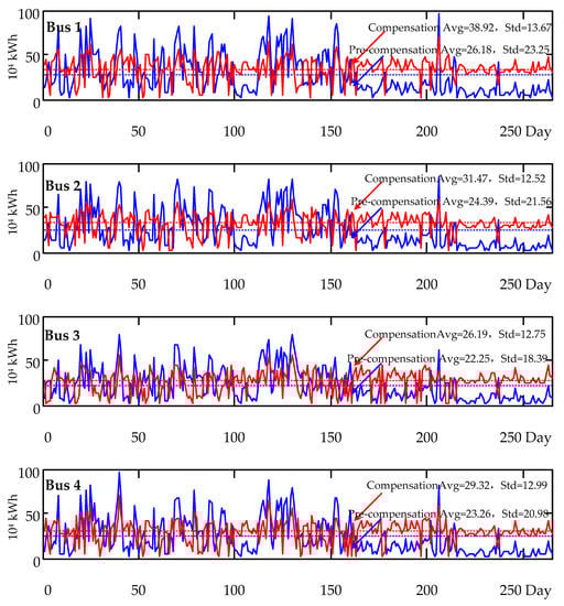
Figure 14.
PR> Avg (PR) battery charging, PR< Avg (PR) battery discharging.
4.2. Case 2
If the wind power output is more than two times the average power, the energy storage unit is charged; when the wind power output is lower than the average power, the energy storage unit is discharged. A comparison of the simulation results is shown in Figure 15. After compensating, the standard deviations of the four buses are 8.03 × 10⁴ kWh, 7.35 × 10⁴ kWh, 6.82 × 10⁴ kWh, and 7.69 × 10⁴ kWh, which are reduced by 15.22 × 10⁴ kWh, 14.21 × 10⁴ kWh, 11.57 × 10⁴ kWh, and 12.99 × 10⁴ kWh, respectively, before compensation. The average outputs after compensation are 38.92 × 10⁴ kWh, 36.17 × 10⁴ kWh, 32.49 × 10⁴ kWh, and 34.5900 × 10⁴ kWh, up 12.74 × 10⁴ kWh, 11.78 × 10⁴ kWh, 10.24 × 10⁴ kWh, and 11.33 × 10⁴ kWh, respectively, before compensation. The compensation effect of Case 2 is better than Case 1, and the energy storage unit is connected to the DC microgrid for moderate adjustment frequency.
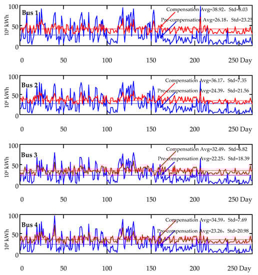
Figure 15.
PR> 2Avg (PR) battery charging, PR< Avg (PR) battery discharging.
4.3. Case 3
If the wind power output is more than three times the average power, the energy storage unit is charged; when the wind power output is lower than the average power, the energy storage unit is discharged. A comparison of the simulation results is shown in Figure 16. After the compensation, the standard deviations of the four buses are 11.67 × 10⁴ kWh, 11.55 × 10⁴ kWh, 9.82 × 10⁴ kWh, and 11.19 × 10⁴ kWh, which are lower than the compensation by 11.58 × 10⁴ kWh, 10.01 × 10⁴ kWh, 8.57 × 10⁴ kWh, and 9.79 × 10⁴ kWh, respectively. The average outputs after compensation are 41.79 ×10⁴ kWh, 39.39 × 10⁴ kWh, 34.67 × 10⁴ kWh, and 37.05 × 10⁴ kWh, respectively 15.61 × 10⁴ kWh, 15 × 104 kWh, 12.42 × 10⁴ kWh, 13.79 × 10⁴ kWh before compensation. The compensation effect of Case 3 is worse than that of Case 2, and the energy storage unit is moderately active.
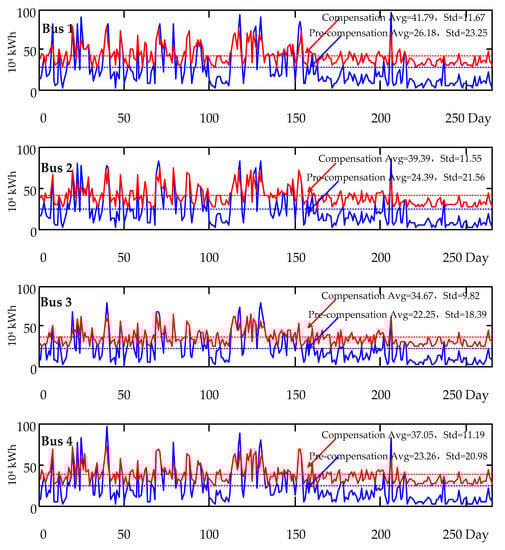
Figure 16.
PR> 3Avg (PR) battery charging, PR< Avg (PR) battery discharging.
Comprehensive comparison of the results of Table 2: Case 1 can ensure that the SOC state of the energy storage unit is higher, but the energy storage unit frequently operates; Case 2 can ensure that the system power fluctuation is minimal and the energy storage unit action frequency is moderate; Power fluctuations are large. Comprehensive comparison shows that the second option is optimal. In order to give full play to the adjustment effect of the distributed energy storage unit on the microgrid, it is also necessary to adjust the SOC of the energy storage unit in advance in conjunction with the wind power forecast data to cope with the fluctuation of the bus voltage. In order to prevent off-site wind power accidents, the forecast and actual operational data should be uploaded to provide a decision-making basis for the superior supervisory unit.
Table 2.
Comparison of three cases (104 kWh).
The distributed energy storage unit is mainly connected to the DC bus at the second layer to keep the bus voltage stable and to suppress the bus line power fluctuation. If the time difference is used, the energy storage system will be frequently charged and discharged to reduce the service life of the energy storage system. If the adjustment is too slow, the wind power fluctuation will not be stabilized, and the system will be safely and stably operated.
5. Conclusions
This paper has presented a distributed drooping control of SOC power exponents and considers the emergency state when communication faults occur. The application of SOC power exponent drooping control in hierarchical control is discussed in this paper. The test results show that the SOC power exponential function droop control works best with Case 2 at layer 2, and the energy storage unit is out of operation and the SOC is self-adjusting at other levels. Finally, the DC microgrid operates in a layered protocol mode. The experimental and simulation results have verified the effectiveness.
Author Contributions
P.L. designed the prototype and was responsible for writing the paper. C.Z. and Y.G. were responsible for guidance in the experiment and thesis writing process. All authors have read and agreed to the published version of the manuscript.
Funding
This research was supported by the National Nature Science Foundation of China under Grants 51877187 and the Science Foundation of Hebei University of Science and technology Grants PYB2019011.
Conflicts of Interest
The authors declare no potential conflict of interest.
References
- Howlader, A.M.; Matayoshi, H.; Sepasi, S.; Senjyu, T. Design and Line Fault Protection Scheme of a DC Microgrid Based on Battery Energy Storage System. Energies 2018, 11, 1823. [Google Scholar] [CrossRef]
- Guo, X.; Yang, Y.; He, R.; Wang, B.; Blaabjerg, F. Transformerless Z-Source Four-Leg PV Inverter With Leakage Current Reduction. IEEE Trans. Power Electron. 2019, 34, 4343–4352. [Google Scholar] [CrossRef]
- Zhang, C.; Li, P.; Kan, Z.; Chai, X.; Guo, X. Integrated Half-Bridge CLLC Bidirectional Converter for Energy Storage Systems. IEEE Trans. Ind. Electron. 2018, 65, 3879–3889. [Google Scholar] [CrossRef]
- Guo, X.; Jia, X. Hardware-Based Cascaded Topology and Modulation Strategy With Leakage Current Reduction for Transformerless PV Systems. IEEE Trans. Ind. Electron. 2016, 63, 7823–7832. [Google Scholar] [CrossRef]
- Bi, H.; Wang, P.; Wang, Z. Common Grounded H-Type Bidirectional DC-DC Converter with a Wide Voltage Conversion Ratio for a Hybrid Energy Storage System. Energies 2018, 11, 349. [Google Scholar] [CrossRef]
- Guo, X.Q.; Yang, Y.; Zhang, X. Advanced Control of Grid-Connected Current Source Converter Under Unbalanced Grid Voltage Conditions. IEEE Trans. Ind. Electron. 2018, 65, 9225–9233. [Google Scholar] [CrossRef]
- Zhi, N.; Zhang, H.; Xiao, X. Switching system stability analysis of DC microgrids with DBS control. In Proceedings of the 2016 IEEE Applied Power Electronics Conference and Exposition (APEC), Long Beach, CA, USA, 20–24 March2016; pp. 3338–3345. [Google Scholar]
- Guo, X.; Yang, Y.; Wang, B.; Blaabjerg, F. Leakage current reduction of three-phase Z-source three-level four-leg inverter for transformerless PV system. IEEE Trans. Power Electron. 2019, 34, 6299–6308. [Google Scholar] [CrossRef]
- Guo, X.; Zhou, J.; He, R.; Jia, X.; Rojas, C.A. Leakage current attenuation of a three-phase cascaded inverter for transformerless grid-connected pv systems. IEEE Trans. Ind. Electron. 2018, 65, 676–686. [Google Scholar] [CrossRef]
- Jiang, T.; Zhang, J.; Wu, X.; Sheng, K.; Wang, Y. A Bidirectional Three-Level LLC Resonant Converter With PWAM Control. IEEE Trans. Power Electron. 2016, 31, 2213–2225. [Google Scholar] [CrossRef]
- Sha, D.; Lin, Q.; You, F.; Wang, X.; Xu, G.; Chen, H. A ZVS Bidirectional Three-Level DC–DC Converter With Direct Current Slew Rate Control of Leakage Inductance Current. IEEE Trans. Ind. Appl. 2016, 52, 2368–2377. [Google Scholar] [CrossRef]
- Jin, L.; Liu, B.; Duan, S. ZVS operation range analysis of three-level dual active bridge DC-DC converter with phase-shift control. IEEE Trans. Ind. Appl. 2019, 55, 362–366. [Google Scholar] [CrossRef]
- Filba-Martinez, A.; Busquets-Monge, S.; Nicolas-Apruzzese, J.; Bordonau, J. Operating Principle and Performance Optimization of a Three-Level NPC Dual-Active-Bridge DC-DC Converter. IEEE Trans. Ind. Electron. 2016, 63, 678–690. [Google Scholar] [CrossRef]
- Uno, M. High Step-Down Converter Integrating Switched Capacitor Converter and PWM Synchronous Buck Converter. In Proceedings of the Intelec 2013; 35th International Telecommunications Energy Conference, SMART POWER AND EFFICIENCY, Hamburg, Germany, 13–17 October 2013. [Google Scholar]
- Li, X.; Zhang, W.; Li, H.; Xie, R.; Xu, D. Design and control of bi-directional DC/DC converter for 30kW fuel cell power system. In Proceedings of the 8th International Conference on Power Electronics - ECCE Asia, Jeju, South Korea, 30 May–3 June 2011; pp. 1024–1030. [Google Scholar]
- Jin, K.; Yang, M.; Ruan, X.; Xu, M. Three-Level Bidirectional Converter for Fuel-Cell/Battery Hybrid Power System. IEEE Trans. Ind. Electron. 2010, 57, 1976–1986. [Google Scholar] [CrossRef]
- Chen, W.; Ruan, X.; Yan, H.; Tse, C.K. DC/DC Conversion Systems Consisting of Multiple Converter Modules: Stability, Control, and Experimental Verifications. IEEE Trans. Power Electron. 2009, 24, 1463–1474. [Google Scholar] [CrossRef]
- Vazquez, A.; Rodriguez, A.; Lamar, D.G.; Hernando, M.M. Advanced Control Techniques to Improve the Efficiency of IPOP Modular QSW-ZVS Converters. IEEE Trans. Power Electron. 2018, 33, 73–86. [Google Scholar] [CrossRef]
- Moghimi, M.; Liu, J.; Jamborsalamati, P.; Rafi, F.H.M.; Rahman, S.; Hossain, J.; Stegen, S.; Lu, J. Internet of Things Platform for Energy Management in Multi-Microgrid System to Improve Neutral Current Compensation. Energies 2018, 11, 3102. [Google Scholar] [CrossRef]
- Anand, S.; Fernandes, B.G. Reduced-Order Model and Stability Analysis of Low-Voltage DC Microgrid. IEEE Trans. Ind. Electron. 2013, 60, 5040–5049. [Google Scholar] [CrossRef]
- Anand, S.; Fernandes, B.G.; Guerrero, J. Distributed Control to Ensure Proportional Load Sharing and Improve Voltage Regulation in Low-Voltage DC Microgrids. IEEE Trans. Power Electron. 2013, 28, 1900–1913. [Google Scholar] [CrossRef]
- Beerten, J.; Belmans, R. Analysis of Power Sharing and Voltage Deviations in Droop-Controlled DC Grids. IEEE Trans. Power Syst. 2013, 28, 4588–4597. [Google Scholar] [CrossRef]
- Cheng, Z.; Li, Z.; Liang, J.; Gao, J.; Si, J.; Li, S. Distributed Economic Power Dispatch and Bus Voltage Control for Droop-Controlled DC Microgrids. Energies 2019, 12, 1400. [Google Scholar] [CrossRef]
- Lu, X.; Sun, K.; Guerrero, J.M.; Vasquez, J.C.; Huang, L. Double-Quadrant State-of-Charge-Based Droop Control Method for Distributed Energy Storage Systems in Autonomous DC Microgrids. IEEE Trans. Smart Grid 2015, 6, 147–157. [Google Scholar] [CrossRef]
- Hu, Y.; Wei, W. Improved Droop Control with Washout Filter. Energies 2018, 11, 2415. [Google Scholar] [CrossRef]
- Oliveira, T.R.; Silva, W.W.A.G.; Donoso-Garcia, P.F. Distributed Secondary Level Control for Energy Storage Management in DC Microgrids. IEEE Trans. Smart Grid 2017, 8, 2597–2607. [Google Scholar] [CrossRef]
- Obaid, Z.A.; Cipcigan, L.M.; Abrahim, L.; Muhssin, M.T. Frequency control of future power systems: reviewing and evaluating challenges and new control methods. J. Mod. Power Syst. Clean Energy 2018, 7, 9–25. [Google Scholar] [CrossRef]
- Wang, Y.; Tan, K.T.; Peng, X.Y.; So, P.L. Coordinated Control of Distributed Energy-Storage Systems for Voltage Regulation in Distribution Networks. IEEE Trans. Power Delivery 2016, 31, 1132–1141. [Google Scholar] [CrossRef]
- Yang, H.; Li, S.; Li, Q.; Chen, W. Hierarchical distributed control for decentralized battery energy storage system based on consensus algorithm with pinning node. Prot. Control. Mod. Power Syst. 2018, 3, 6. [Google Scholar] [CrossRef]
© 2020 by the authors. Licensee MDPI, Basel, Switzerland. This article is an open access article distributed under the terms and conditions of the Creative Commons Attribution (CC BY) license (http://creativecommons.org/licenses/by/4.0/).