Article

Dynamic Slot Multiplexing Under Operating Modes for TDMA-Based Real-Time Networking Systems

The University of Kitakyushu, Kitakyushu, Fukuoka 808-0135, Japan
Electronics 2020, 9(2), 224; https://doi.org/10.3390/electronics9020224
Submission received: 28 December 2019 / Revised: 27 January 2020 / Accepted: 27 January 2020 / Published: 29 January 2020
(This article belongs to the Special Issue Emerging Trends in Industrial Communication)

Abstract

:
The Time Division Multiple Access (TDMA) scheme has been proposed as the one which assures real-time messaging in a networking system. In the TDMA scheme, a networking system operates based on time slots which are defined as discrete time units. Some messages are periodically and exclusively assigned to their own time slots and are assured to be sent between network nodes by their own deadline. In this paper, we note that an operating situation of a system determines what functions of the system run. More concretely, an operating situation determines what data the system requires and how frequently it requires them. We propose to introduce operating modes, each of which reflects its own operating situation, to the TDMA scheme. An operating mode is specified by a set of communication signals which are active under the operating mode. We propose a dynamic slot multiplexing (DSM) technique which switches operating modes and assignments of communication signals to time slots adaptively with operating situations. System designers are to schedule all messages of communication signals for every operating mode so that the messages are sent by their own deadline. Compared with a single-mode TDMA system, in which a single message schedule is determined for all communication signals, our approach optimally determines a message schedule for each operating mode so that it can avoid wasting networking resources. Our experiment shows that DSM technique achieves about 21%-37% lower operating frequency than static slot multiplexing one.

1. Introduction

Electronics is getting increasingly essential to incarnate highly functional cars including autonomous ones. An in-vehicular communication system is a part of car electronics and one of the key technologies indispensable for realizing present and future cars. The number of electronic devices and their communication systems increases in a single car as it evolves. The increase in the amount of electronic devices causes the increase of fabrication cost. From a viewpoint of economy, fabrication cost reduction is strongly required for mass production of cars.
A controller area network (CAN) is the de facto network standard for in-vehicular communication [1]. The CAN adopts a priority-based arbitration which offers designers flexibility in configuring a vehicular network. The CAN is also adaptive with a change of operating situations as far as a prioritized messaging works well. It, however, lacks determinacy in communication latency because of priority-based arbitration. A lack of determinacy in communication latency causes uncertainty in arrival time of data and makes it hard to ensure that a network node communicates with another by its deadline. The CAN, therefore, is incapable of implementing automotive applications such as x-by-wire systems [2].
A time division multiple access (TDMA) scheme is a communication technology in which time to use communication resources such as a communication bus is divided into time slots which are assigned to network nodes. Each network node transfers their own messages with their own time slots with its deadline satisfied. A TDMA scheme provides quite high determinacy regarding communication latency while it provides a variety of network bandwidths. The FlexRay network protocol is a TDMA-based communication network standard [3]. In the FlexRay protocol, two TDMA schemes are available: STDMA (Static TDMA) and FTDMA (Flexible TDMA) ones. Many researchers have studied the TDMA scheme [4] and the TDMA scheme is widely adopted in many domains such as phone systems, vehicular systems, factory control systems and robot systems where real-time messaging is required.
It is a challenging theme to study a design methodology that builds TDMA-based systems. It is highly demanded to realize a TDMA-based network system at a cheap cost for commercial success. We proposed a design approach for minimizing the operating frequency of a communication bus by optimizing the size of frames of payload segments [5]. We proposed another design approach which minimized the operating frequency based on slot multiplexing [6]. Slot multiplexing allows assignment of every communication signal not to a time slot but to a pair of a cycle and a time slot. We also proposed a design approach for a bridged bus-based TDMA system so that the fabrication cost was minimized [7].
In this paper, we note that an operating situation of a system determines what functions of a system are executed. More concretely, an operating situation determines what data the system requires and how frequently it requires them. We propose to introduce operating modes, each of which reflects its own operating situation, to the TDMA scheme. Adoption of multiple modes offers designers flexibility in message scheduling as the CAN does. Each operating mode is specified by a set of communication signals which are active under the corresponding operating mode. A task of system designers is to schedule all messages of communication signals so that the messages are sent by their own deadline. We propose a dynamic slot multiplexing (DSM) technique which switches operating modes and assignments of communication signals to time slots adaptively with operating situations. Compared to a conventional system [6] which is equivalent to a single-mode TDMA system where a single message schedule is determined for all communication signals, our approach determines a message schedule for each operating mode so that it can avoid wasting networking resources. We take a stand that reduction of an operating frequency of a communication bus contributes to lowering cost of wire harness and circuitry. Generally speaking, the faster the speed of communication is, the more expensive the cost of wire harness and circuitry is. Reduction of operating frequency contributes to adoption of slower and cheaper networking circuitry or contributes to successful message schedules without adopting faster and expensive networking circuitry. We present an optimization problem in which a message schedule for each and every operating mode is optimized so that operating frequency of wire harness is minimized for given operating modes and their own set of communication signals. Our experiment shows that the DSM technique achieves about 21-37% lower operating frequency than static slot multiplexing one. We use a FlexRay networking system as an example of the TDMA systems. Our idea is applicable to other TDMA-based systems.
Section 2 summarizes the FlexRay network protocol which is an example of TDMA approaches. Section 3 proposes a dynamic slot multiplexing technique which switches operating modes of TDMA-based network. Section 4 shows our experiments which show the effectiveness of our dynamic slot multiplexing technique. Section 5 concludes this paper.

2. FlexRay Network Protocol

In this section, we summarize the FlexRay network protocol [3]. More detail is found in the specification document [3].

2.1. Timing Hierarchy

The FlexRay networking protocol specifies timing hierarchy which consists of four abstraction levels: microtick level, macrotick level, arbitration grid level, and communication cycle level as shown in Figure 1.
A communication cycle (CC) level is the highest level of timing hierarchy. A communication cycle (CC) is defined as a period which periodically and repeatedly appears and consists of four segments: static segment (SS), dynamic segment (DS), symbol window (SW) and network idle time (NIT). The static segment is a period during which the static TDMA (STDMA) is used to arbitrate messaging. The dynamic segment is a period during which flexible TDMA (FTDMA) is used to arbitrate messaging. The symbol window is a period during which symbols can be transmitted. The network idle time is a communication-free period and concludes each communication cycle. This paper mainly focuses on the static segments where time slots are deterministically assigned to communication signals. System designers can configure up to 64 cycles to meet their requirement. Each cycle can differ from another regarding assignment of communication signals to time slots in static segments. Each communication cycle is executed every 64 cycles.
The next lower level, the arbitration grid level, contains the arbitration grid. In a static segment the arbitration grid consists of consecutive time intervals, called static slots. In the dynamic segment the arbitration grid consists of consecutive time intervals, called minislots.
The arbitration grid level builds on the macrotick level that is defined by the macrotick. A macrotick represents the smallest granularity unit of the global time. Designated macrotick boundaries in Figure 1 are called action points. An action point is an instant in time at which a transmitter starts a transmission of a FlexRay frame.
The lowest level in the hierarchy is defined by microticks. A microtick is an interval of time and is a node-local concept.

2.2. Frame Format

A FlexRay frame is defined as a container for transmission which contains three segments: header segment, payload segment and trailer segment. Figure 2 shows the FlexRay frame format. A network node is to send a frame of data on a network such that a header segment appears first, followed by a payload segment, and then followed by a trailer segment, which is transmitted last. Within the individual segments the node shall transmit the fields in left to right order as depicted in Figure 2.

2.3. Frame Encoding

A FlexRay frame is encoded with five sequences: a transmission start sequence (TSS), a frame start sequence (FSS), a byte start sequence (BSS), a frame end sequence (FES), and a dynamic trailing sequence (DTS). A TSS and an FSS are inserted at the beginning of a frame. Every byte of a frame has its BSS before it. An FES is added after a frame. A DTS is added in a dynamic segment immediately after an FES of a frame.
Decoded frames in a static segment is shown in Figure 3. A TSS initiates proper connection setup through the network. A transmission node generates a TSS that consists of a continuous LOW for a period given by a FlexRay parameter. An FSS follows the TSS. An FSS compensates for a possible quantization error in the first byte start sequence after the TSS. An FSS consists of one HIGH bit time. The node shall append an FSS to the bit stream immediately following the TSS of a transmitted frame. A BSS provides bit stream timing information to the receiving devices. The BSS shall consist of one HIGH bit time followed by one LOW bit time. Each byte of frame data shall be sent on the channel as an extended byte sequence that consists of one BSS followed by eight data bits. An FES marks the end of the last byte sequence of a frame. The FES shall consist of one LOW bit time followed by one HIGH bit time. The network node shall append an FES to the bit stream immediately after the last extended byte sequence of the frame.
Figure 2 shows a frame consists of header, payload, and trailer segments. We use notations B hd and B tl for the header size and the trailer size in bits, respectively. The size of a payload segment shall be fixed and identical among all frames in a static segment. We use notation P for the payload size in the number of 16-bit words. The standard for FlexRay states that the size of a payload shall be an even number in bytes between 0 to 254. The size of a frame in bits, F, is shown as follows:
F = B hd + B tl + 16 P .
The size of an encoded frame in bits, F enc , is formulated as follows:
F enc = F + B TSS + B FSS + F 8 · B BSS + B FES + B DLM + B IDL = 1 + B BSS 8 F + B TSS + B FSS + B FES + B DLM + B IDL = 16 + 2 B BSS P + O ,
O = 1 + B BSS 8 B hd + B tl + B TSS + B FSS + B FES + B DLM + B IDL ,
where B TSS , B FSS , B BSS , B FES , B DLM , and B IDL are the numbers of bit time for a TSS, an FSS, a BSS, an FES, a channel idle delimiter, and a channel idle, respectively.

2.4. Slot Multiplexing

The FlexRay standard specifies cycle-independent slot assignment as the method of assigning, for a given channel, the set of all communication slots with a specific slot number to a network node (i.e., on the given channel, slots with the specific slot number are assigned to the node in all communication cycles). The FlexRay standard specifies cycle-dependent slot assignment as the method of assigning, for a given channel, an individual slot (identified by a specific slot number and a specific cycle counter number) or a set of slots (identified by a specific slot number and a set of communication cycle numbers) to a node. The FlexRay standard specifies slot multiplexing (SM) as the technique of assigning, for a given channel, slots with the same slot identifier to different nodes in different communication cycles. Figure 4 shows an example of slot multiplexing. The FlexRay standard specifies that one may use up to 64 ( = N cycles ) communication cycles for slot multiplexing. The communication cycles are recurrently executed with an identical period that depends on the number of communication cycles. This paper assumes that one uses 64 communication cycles for slot multiplexing.

3. Dynamic Slot Multiplexing

In this paper, we note that a situation in which a system operates determines what functions of the system run in industrial applications such as automotive one. More concretely, the operating situation determines what data the system requires and how frequently it requires them. We propose to introduce operating modes, each of which reflects its own operating situation, to the TDMA scheme. System designers are to specify a set of active communication signals for each and every operating mode. In this paper, we propose dynamic slot multiplexing (DSM) which switches operating modes and assignments of communication signals to time slots adaptively with operating situations. Compared to a single-mode TDMA system [6], in which a single message schedule is determined for all communication signals, DSM determines a message schedule for each operating mode and switch operating modes adaptively with operating situations so that it can avoid wasting networking resources. We present an optimization problem in which a message schedule for each and every operating mode is optimized so that operating frequency of wire harness is minimized for given operating modes and their own set of communication signals.

3.1. Optimization Problem in DSM

Let us assume that a set of network nodes N are given and constitute a network. We define a communication signal as the behavior of a network node in requesting to send a constant size of data to one or more network nodes by its deadline periodically or aperiodically. We also define a communication message as an instance of a communication signal which a network node requests to send via the FlexRay bus(es). From an aspect of implementation, a communication message is split into one or more frames which are data structures for transmission via bus(es). For simple problem formulation we assume a network system in which all communication messages are requested to be sent periodically. A communication signal is defined as a 4-tuple ( N , C , D , B ) where N is a sender node, C is a period between successive communication messages, D is a relative deadline from its request, and B is the size of a communication message in bits. We assume that sender node N requests to send a datum of B bits every C time units to all the network nodes and finish sending it within duration D from its request.
We assume that N sig communication signals of a TDMA-based networking system are given and all communication messages of the signals are scheduled over time slots of static segments. A static segment consists of q ( N sig ) time slots and we treat q as a variable. We specify a communication signal S i by a 4-tuple ( N i , C i , D i , B i ) . No more than a static slot is assigned to a communication signal within a communication cycle. We represent the baud rate of a communication bus of a target network by w [bps]. The objective function in our optimization problem is to minimize w.
In this paper, we note that a situation in which a system operates determines what functions of the system run in industrial applications such as automotive one. An operating mode is specified by a set of active communication signals, whose messages are sent under its situation. Now let us assume that system designers specify N mode operating modes and that a set of M = { M 1 , M 2 , , M N mode } is given. The following constant E i , j indicates whether or not the corresponding communication signal is active.
E i , j = 1 Communication   signal   s j   is   active   under   operating   mode   M i . 0 Otherwise .
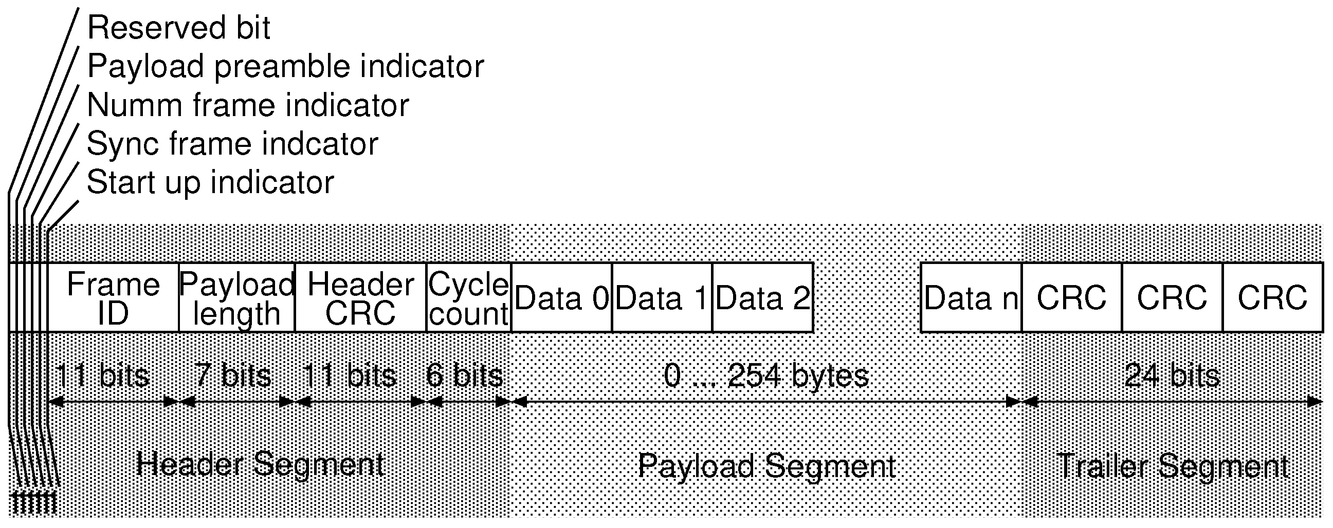
A communication message of a communication signal is split into one or more frames. As shown in Figure 2, a frame consists of a header segment, a payload segment, and trailer segment. We notate the size of a header segment as B hd and that of trailer segment as B tl . The size of a payload segment, which system designers specify, is identical in any static static segments. A payload segment consists of p ( 0 p 127 ) 16-bit words. The size of a frame, f, is shown as follows.
f = B hd + B tl + 16 p .
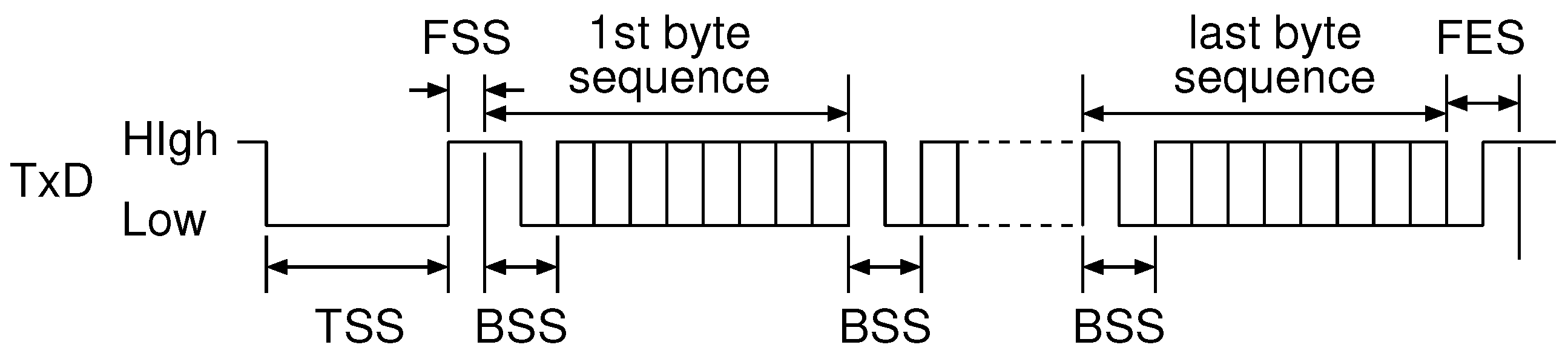
The size of an encoded frame, f enc , is shown as follows.
f enc = f + B TSS + B FSS + f 8 · B BSS + B FES + B DLM + B IDL = 1 + B BSS 8 f + B TSS + B FSS + B FES + B DLM + B IDL = 16 + 2 B BSS p + O , O = 1 + B BSS 8 B hd + B tl + B TSS + B FSS + B FES + B DLM + B IDL .
where B TSS , B FSS , B BSS , B FES , B DLM , and B IDL are the numbers of bit time for a TSS, an FSS, a BSS, an FES, a channel idle delimiter, and a channel idle, respectively.
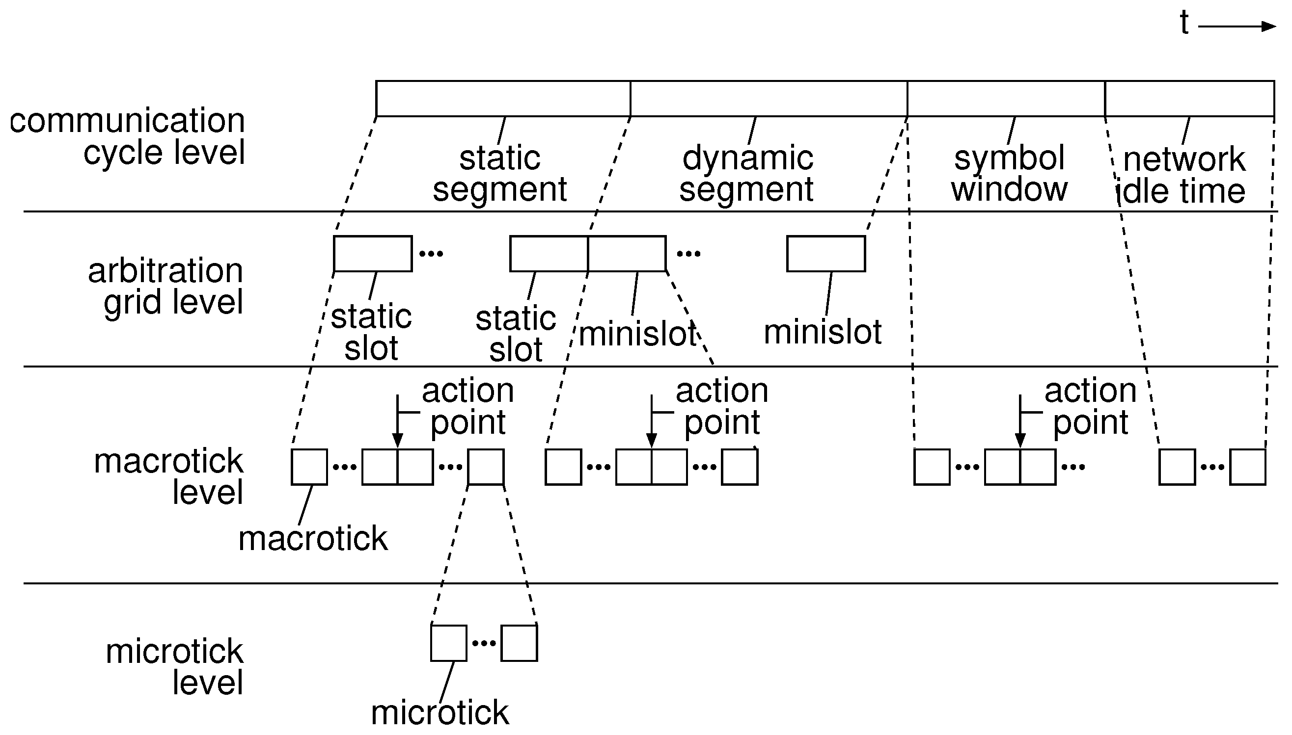
Let us discuss time for a communication cycle t cc . A frame is sent using a static slot in a static segment. For a simple explanation, we assume that system designers conform to deadline constraints as far as a networking system operates normally. We also assume that a communication cycle consists of a static segment. Our optimization problem can be easily extended to a network system which has a dynamic segment, symbol window, and network idle time. Please note that message scheduling technique using dynamic segments is out of scope of this paper and should be discussed as another research topic. From our assumption, time for a communication cycle t cc is equal to time for q static slots as follows.
t cc = q · f enc w
q is an integer variable standing for the number of static slots constituting a static segment and w is a baud rate of a communication bus of a FlexRay networking system.
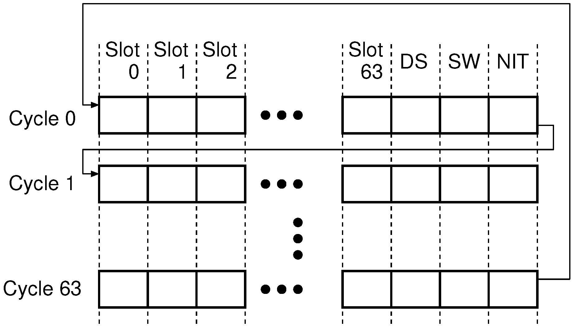
In the FlexRay standard, system designers may adopt a slot multiplexing technique by which they assign multiple communication cycles to a static slot by distinguishing 64 communication cycles. More concretely, they may assign a communication cycle not to a static slot but to a pair of a static slot and a communication cycle. The 64 communication cycles are periodic and recurrent. Adoption of slot multiplexing help system designers effectively use static slots and avoid wasting static slots while they must make efforts towards obtaining an optimal design over larger design space. For making an optimization problem simple, we introduce a binary variable a i , j which indicates that 2 j static slots are assigned to communication signal S i and that a static slot is used every 2 6 j communication cycles.
a i , j = 1 if   communication   signal   S i   uses   a   static   slot   every   2 6 j   cycles . 0 otherwise
As the number of assignments of communication signal S i to communication cycles is one, the following constraint is introduced.
i , j = 0 6 a i , j = 1 .
Communication signal S i requires B i 16 p static slots to send its communication message. As transmission time to send a message of a communication signal is not more than its period of transmission requests, the following constraint is introduced.
i , B i 16 p j = 0 6 2 6 j a i , j t cc C i .
A communication signal uses 2 j communication cycles out of 64 communication cycles and uses one communication cycle every 2 6 j communication cycles. The number of selections is 2 6 j . We introduce the following binary variable c i , l ( 1 l 64 ) for indicating the first communication cycle.
c i , l = 1 if   communication   cycle   l   is   the   one   communication   signal   i   first   uses   among   64   cycles . 0 otherwise .
We introduce the following constraint from the definitions of variables a i , j and c i , l .
i , j , a i , j = 1 l = 1 2 6 j c i , l = 1 and l > 2 6 j , c i , l = 0
We introduce the following binary variable which indicates whether or not communication signal S i
d i , m , n = 1 if   signal   S i   uses   cycle   m   under   operating   mode   n . 0 otherwise .
As a communication signal uses a cycle every 2 6 j cycles under the corresponding operating modes, the following constraint is introduced.
i , j , l 2 6 j , 0 h 2 j 1 , a i , j = 1 and c i , l = 1 and E n , i = 1 d i , l + h · 2 6 j , n = 1
The number of static slots of a communication cycle, q, is the maximum number of communication signals which are assigned to the communication cycle as follows.
q = max n , m i d i , m , n
We discuss a transmission process of a communication message and its constraint. 
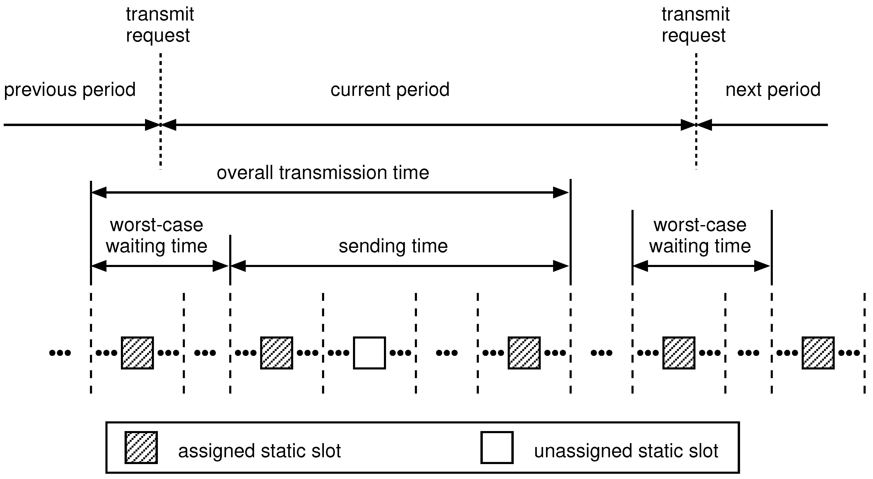
Figure 5 shows a transmission process in which a communication message is periodically transmitted. Wait time occurs in each message transmission before the first frame gets on the bus. We assume that a communication signal may be assigned to any static slot of the corresponding communication cycles. We regard the interval between two successive frames as the worst-case wait time.
j = 0 6 2 6 j a i , j t cc
Wait time is followed by time for sending frames. A communication signal uses any static slot of the corresponding communication cycle. Time for sending frames of a communication message is conservatively introduced as follows.
B i 16 p 1 j = 0 6 2 6 j a i , j + 1 t cc
The worst-case latency to send a communication message of signal S i is the summation of the worst-case wait time (1) and the sending time of all frames (2) as follows.
t i = B i 16 p j = 0 6 2 6 j a i , j + 1 t cc
Since it is required that the worst-case latency t i of communication signal i is not more than its deadline, the following constraint is introduced.
i , B i 16 p j = 0 6 2 6 j a i , j + 1 t cc D i
Our mathematical model is given as follows.
Minimize the cost function w
subject to
  • i , j = 0 6 a i , j = 1 .
  • i , B i 16 p j = 0 6 2 6 j a i , j t cc C i .
  • t cc = q · f enc w .
  • f enc = ( 16 + 2 B BSS ) p + O .
  • O = 1 + B BSS 8 B hd + B tl .
  • i , j , a i , j = 1 l = 1 2 6 j c i , l = 1 and l > 2 6 j , c i , l = 0 .
  • i , j , l 2 6 j , 0 h 2 j 1 , a i , j = 1 and c i , l = 1 and E n , i = 1 d i , l + h · 2 6 j , n = 1 .
  • q = max n , m i d i , m , n
  • i , B i 16 p j = 0 6 2 6 j a i , j + 1 t cc D i .
Variables
  • w is a real variable.
  • p is an integer variable.
  • q is an integer variable.
  • a i , j is a binary variable.
  • t cc is a real variable.
  • f enc is an integer variable.
  • c i , l is a binary variable.
  • d i , m , n is a binary variable.

3.2. Simulated Annealing

Simulated annealing is a probabilistic method proposed by Kirkpatrick et al. for finding the global minimum of a cost function that may possess local minima [8]. We developed a simulated annealing-based scheduler that optimizes both slot multiplexing for two buses and assignment of each signal to a bus. The pseudo-code for the simulated annealing algorithm is shown in Figure 6. The code for the scheduler was written in C++. We used the values shown in Table 1 as the parameters for the simulated annealing-based scheduler. We obtained solutions for 16 ( 2 × 4 × 2 ) combinations of parameters with our SA-based scheduler.

4. Experiment

4.1. Experimental Setup

We used the network parameters, which Park et al. gave in their paper, for our experiment [9]. We assumed that there is not channel idle time after a channel idle delimiter.
We developed a solver in C++ which is based on SA and obtains a solution to the optimization problem shown in Section 3.1. We used parameters for SA, which are shown in Table 2.
The SAE benchmark signal set is an instance of communication signal set for distributed control system of automobiles [10]. The SAE benchmark is common among researchers in the research domain of designing an in-vehicle network. The SAE benchmark consists of 53 types of communication signals. The SAE benchmark signal set assumes seven network nodes: Battery, Brakes, Trans, V/C, I/M C, Driver, and Ins. The detailed table for the SAE benchmark was given by Kutlu et al. [10]. We examined operating frequencies of a communication bus in a condition that the number of operating modes is one to five. We generated a uniform random value from 1 to 2 N mode 1 to each communication signal. Depending on digits of the random value of a signal, we determined whether the signal was active or inactive. For example, a signal is active under mode 1 and is inactive under modes 2 and 3 if a random value is 100 for a 3-mode case. We assumed 20 cases for each operating mode.

4.2. Experimental Result

Figure 7 shows experimental results. The horizontal axis indicates the number of operating modes and the vertical axis indicates operating frequency achieved by a solution which our solver found. Results for one operating mode corresponds to conventional slot multiplexing, i.e., static slot multiplexing [6]. In our experiment, we generated 20 signal sets each of which differs from others in terms of operating mode setting. Operating frequency changes depending on a given signal set. The maximum operating frequency among 20 signal sets in each mode is shown by a broken line and the minimum one by a solid line. For example, operating frequency was reduced by about 21–37% for 2-mode cases, compared to the 1-mode case.

5. Conclusions

In this paper, we presented the dynamic slot multiplexing approach based on TDMA scheme and the optimization problem in which assignment of signals to static slots in each mode was optimized so that operating frequency was minimized. Operating frequency was reduced by about 21–37% for 2-mode cases, compared to the 1-mode case. Future work includes the following items.
  • Examination of latency for mode switching.
  • Optimization of both assignment of signals to time slots and network topology such as hierarchical buses.

Funding

This research was funded by JSPS KAKENHI Grant Number JP17899116.

Conflicts of Interest

The authors declare no conflict of interest.

References

  1. CAN Specification 2.0; Robert Bosch GmbH: Stuttgart, Germany, 1991.
  2. Cena, G.; Valenzano, A. Achieving Round-Robin Access in Controller Area Networks. IEEE Trans. Ind. Electron. 2002, 49, 1202–1213. [Google Scholar] [CrossRef]
  3. Makowitz, R.; Temple, C. Flexray—A Communication Network for Automotive Control Systems. In Proceedings of the 6th IEEE International Workshop on Factory Communication Systems (WFCS), Torino, Italy, 28–30 June 2006. [Google Scholar]
  4. Pozo, F.; Rodriguez, G.; Hansson, H. Methods for Large-Scale Time-Triggered Network Scheduling. Electronics 2019, 8, 738. [Google Scholar] [CrossRef] [Green Version]
  5. Sugihara, M.; Iwanaga, A. Minimization of FlexRay Bus Bandwidth for Hard Real-Time Applications. IPSJ J. Inf. Process. 2013, 1, 46–52. [Google Scholar] [CrossRef] [Green Version]
  6. Sugihara, M.; Iwanaga, A. Slot Multiplexing Optimization for Minimizing the Operating Frequency of a FlexRay Bus under Hard Real-Time Constraints. IPSJ J. Inf. Process. 2013, 21, 563–571. [Google Scholar] [CrossRef] [Green Version]
  7. Sugihara, M. Minimization of the Fabrication Cost for a Bridged-Bus-Based TDMA System under Hard Real-Time Constraints. IEICE Trans. Inf. Syst. 2014, 97, 3041–3051. [Google Scholar] [CrossRef] [Green Version]
  8. Kirkpatrick, S.; Gelatt, C.; Vecchi, M. Optimization by simulated annealing. Science 1983, 220, 671–680. [Google Scholar] [CrossRef] [PubMed]
  9. Park, I.; Sunwoo, M. FlexRay Network Parameter Optimization Method for Automotive Applications. IEEE Trans. Ind. Electron. 2011, 58, 1449–1459. [Google Scholar] [CrossRef]
  10. Kutlu, A.; Ekiz, H.; Powner, E. Performance Analysis of MAC Protocols for Wireless Control Area Network. In Proceedings of the International Symposium on Parallel Architectures, Algorithms, and Networks, Bejing, China, 12–14 June 1996. [Google Scholar]
Figure 1. Timing hierarchy specified in the FlexRay protocol.
Electronics 09 00224 g001
Figure 2. Frame format.
Electronics 09 00224 g002
Figure 3. Frame encoding.
Electronics 09 00224 g003
Figure 4. Slot multiplexing.
Electronics 09 00224 g004
Figure 5. Wait time and transmission time of a communication message.
Electronics 09 00224 g005
Figure 6. General procedure for simulated annealing.
Electronics 09 00224 g006
Figure 7. The number of operating modes vs operating frequency.
Electronics 09 00224 g007
Table 1. Network parameters.
FactorLength
Header w/o BSS5 B/frame
Header w BSS45 bits/frame
Trailer w/o BSS3 B/frame
Trailer w BSS27 bits/frame
TSS9 bits/frame
FSS1 bit/frame
FES2 bits/frame
Idle delimiter11 bits/frame
Action point offset1 MT/frame, 10 bits/frame
BSS2 bits/frame byte
Table 2. Parameters for Simulated Annealing.
S 0 A solution obtained without slot multiplexing [5]
T 0 100
α 0.9999, 0.99999
β 1.00001, 1.0001, 1.001, 1.01
Initial value for M100, 200

