Abstract
Recent advances in communication systems provide an enabling technology for aircraft connection and safety. A promising communication system that uses stratospheric platforms provides an efficient and improved communication performance and can be an efficient solution for establishing communication networks for aviation. Therefore, in this paper, a novel communication network based on stratospheric basestation (SB) is proposed to provide fifth-generation (5G) and beyond services for civil aviation aircrafts to improve global flight connectivity, control, and safety. The proposed aircraft–SB network is demonstrated, and its coverage geometry is modelled and investigated. As the 5G and beyond networks use millimeter wave frequency bands (mm-wave), the performance of different atmospheric losses including gaseous absorption, rain, and fog/cloud is analyzed to investigate the system’s practical feasibility at different 5G proposed frequencies ranging from 3.5 to 66 GHz through a flight model including three distinct stages which are takeoff/landing, climbing/descending, and cruise stages. Also, handover scenarios in the proposed aircraft–SB network are investigated and analyzed at the proposed 5G frequencies. In addition, the aircraft–SB 5G network is compared to the most recent low-Earth orbit (LEO) Internet satellites where the proposed system is expected to provide low latency, less atmospheric attenuation, longer aircraft–SB link duration, and very low handover rate.
1. Introduction
1.1. Background
Aviation is one of the leading worldwide industries in which more than 4.3 billion passengers are carried annually across the world [1]. Among other transportation means, aviation is the most fast, safe, and resilient. It forms the major contributor to the global economy and helps global e-commerce development. Every year, about 1.4 billion tourists are transported across countries [1]. Also, aviation provides the fastest techniques for many crisis management and relief events such as forest fire extinguishing, transferring injured people during volcanoes, and tsunamis and floods. One of the most important and permanent aviation applications is passenger transportation. In a few hours onboard a civil aircraft, we can span the Earth over different continents and cross countries’ boundaries which requires supporting subsystems onboard the aircraft to help passengers enjoy and even continue their work during flight through high speed Internet connectivity. For aircraft monitoring and safety, onboard aviation control and communications data are very important and should be connected to ground airport tracking and monitoring systems where several measurement data of these aircraft subsystems should be sent for analysis during flight to reduce flight accidents or the expectation of any onboard subsystems failures. Therefore, the International Civil Aviation Organization (ICAO) [2] has suggested three data domains which are needed for aviation including passenger entertainment services, aircraft information services, and aircraft control data, where all these services should be provided at high speed and with reliable Internet connection. However, the current aviation communication networks that use satellites or terrestrial networks have very limited bandwidths to provide high-speed Internet connections to onboard passengers during flight along with transmission of extensive aircraft measurement and control data. On the other hand, terrestrial high-speed broadband Internet connectivity is currently available through wireless fifth-generation (5G) cellular networks and a few Gbps data rates is expected by using massive multi-input multi-output (MIMO) techniques at the millimeter-wave (mm-wave) bands [3,4,5]. However, these high data rates can be achieved at very small cell dimensions due to the high atmospheric attenuation at the mm-wave 5G frequencies [6] and requires special analysis and investigation for application in aviation systems. In addition, the current satellite communication networks [6,7,8,9] have operational difficulties such as frequent handovers during the long service duration needed by aircrafts in long distance flights.
A recent and efficient compromise solution between terrestrial and satellite systems is the stratospheric basestation (SB) which is also known as high-altitude platform (HAP) [10]. The SB is an airship that flies at stratospheric altitudes of about 20 km high and can provide high-performance communication for many applications including mobile communications, surveillance, monitoring and remote sensing. It is expected that most limitations of conventional communication systems will be mitigated by using SBs where a global area and high-performance connectivity can be provided at lower system cost relative to satellite systems.
1.2. Paper’s Contribution
The ambitious features and capabilities of SB communication system make it a candidate for providing aircrafts with real high-speed Internet connectivity. Therefore, in this paper, a novel stratospheric communication network is proposed for broadband high-speed Internet provision for aviation applications. The proposed network is demonstrated, and its coverage geometry and structure are modelled. As the provision of high-speed Internet connectivity is mainly impacted by the atmospheric attenuation, therefore, the proposed network performance at 5G mm-wave bands is analyzed and investigated at different atmospheric attenuation sources such as the permanent atmospheric gaseous absorption and other temporary rain and fog/cloud attenuations to stand on the feasibility of the system and choose the appropriate and reliable operational frequency bands. Finally, the proposed SB-aviation communication network aspects are compared with the very recent satellite systems for global Internet provision for aviation.
1.3. Paper’s Organization
Following Section 1, Section 2 provides a detailed related work in the field of the paper. Section 3 introduces the stratospheric broadband aeronautical network and Section 4 provides a geometrical modelling of this network. Section 5 demonstrates the concept of a cellular aircraft–SB network while Section 6 investigates the impact of the atmospheric gaseous attenuation during a complete flight profile. In Section 7, other temporary atmospheric attenuation factors are investigated and in Section 8, the proposed system feasibility is discussed. Finally, Section 9 concludes the paper.
2. Related Work
For aircraft near tropopause altitudes over oceans and wide deserts, the only current practical and feasible wireless communication can be achieved using low-Earth orbit (LEO) satellites which provide limited broadband Internet speeds of few Mbps or even lower per user [7]. For example, Inmarsat satellites [8] provide global mobile connectivity for aviation where passengers onboard an aircraft are kept connected through broadband Internet services and the maintenance data can be sent also to ground for analysis and improved aircraft safety. Although LEO satellites provide wide coverage and global connectivity, they suffer from short orbital periods and visibility duration and requires also very frequent handover processes which complicates the system operation and reduces the availability of the network connections. For example, the recent deployed Starlink satellites [9] at 550 km orbit altitude or OneWeb satellites [10] orbiting at 1200 km altitude are only visible for a few minutes per satellite. In addition, the very high speed of LEO satellites results in large Doppler frequency shifts during flight which complicates the system operation and its related communication circuits. In addition, the other medium and geostationary satellite orbits suffer from even more operational difficulties including larger signal attenuation and longer delay time [11]. Recently in [11], “GeoSurf” polar satellites constellation have been designed at altitudes ranging from 1500 up to 35,876 km which provide communication over zenith paths with most of the advantages of satellites at different altitudes. However, the continuous movement of satellites requires complex communication infrastructure and inter-satellite link design. On the other hand, aircraft can also communicate with ground-based transmitters through air-to-ground connectivity (ATG) [12,13,14,15,16,17,18] using L-band digital aeronautical communication system (LDACS). However, the ATG communication channel suffers severely from multipath fading [16] and the L-band suffers from congestion [13] and did not become a suitable candidate for providing high-speed Internet connectivity for aircraft to support the three data domains required by ICAO [2]. Also, ATG suffers from atmospheric losses and ground terrains which impacts the communication link performance and the high speed of the aircraft along with the required very large number of terrestrial transmitters indicates that frequent handovers during flight must be performed. In addition, there is a lack of connectivity in isolated regions such as wide deserts and oceans where there are no ground transmitters are available. Another solution for aircraft Internet provision uses air-to-air (A2A) connectivity through aeronautical ad hoc network (AANET) which has been proposed to provide aircraft with Internet above clouds [19,20,21,22,23]. In AANET, the in-flight aircrafts are interconnected to spread the connectivity among them in an ad-hoc manner with enhanced capacity relative to ATG. Also, AANET may provide limited continuous connection over isolated regions where no ground transmitters are available. However, AANET suffers from many operational challenges [21] such as continuous mobility issues, congestion, threats, and propagation and interference impairments. Therefore, there should be an efficient and feasible communication network to achieve the goal of providing aviation with high-speed broadband Internet services to improve the aircraft safety, monitoring, control and provide passengers with efficient high-speed connectivity during flight.
3. Stratospheric Broadband Aeronautical Network
Civil aircraft can be connected efficiently to broadband Internet services during flight by stratospheric basestations compared to LEO satellite systems. The stratospheric basestations fly at altitudes ranging from 20 to 50 km high in the stratosphere in the form of helium-filled airships carrying communications payloads. Other platform configurations can be utilized such as unpiloted aircrafts or unmanned aerial vehicles which require flying in circular paths to maintain its corresponding coverage area. However, stationary airship SBs will be considered in this paper due to its reliable and stable performance with longer service duration. The optimal altitude for SBs is approximately 20 km where the wind speed is minimum at this height that help in reducing the positional drifts. At this altitude, a SB can cover a circular area of approximately 1000 km diameter on the ground [10,24] which can be further extended for flying aircraft. Figure 1 displays the system architecture for stratospheric broadband aeronautical network where aircrafts can be served by the line-of-sight SBs during flight period. Broadband communications services provision can be provided continuously even during landing or staying at airports. A network of SBs can provide broadband services during the whole flight time if several SBs are linked through microwave or optical links. A local central gateway station for broadband services provision is linked to the stratospheric network through backhaul links to one of the nearby main SB, while other neighbouring SBs can be linked with this main SB to extend the network coverage for remote regions such as oceans or wide deserts. The network can be expanded to cover several neighbouring countries forming a worldwide stratospheric aeronautical communication network. Over oceanic regions, the high altitude of flying aircrafts provides longer communication range, so a smaller number of SBs is required over these regions.
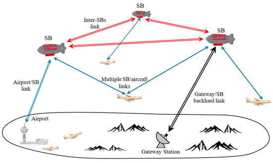
Figure 1.
Stratospheric basestations wireless network for aviation.
4. System Geometrical Modelling
In this section, the network geometry is described and analyzed. The SBs are located at height from the ground surface (usually measured from sea level) as shown in Figure 2. If the aircraft flies at altitude , and the Earth’s radius is , then the maximum range from the SB to the aircraft can be deduced as follows:
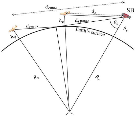
Figure 2.
A simple aircraft–stratospheric basestation (SB) communication link geometrical model.
From triangle ,
or,
then,
Logically, has a solution which includes the negative sign of the square root. Then is finally simplified and given by:
where is the pointing angle from the SB to the aircraft measured from the SB height and is therefore given by:
The communication range lies between minimum and maximum values where the minimum value is given by:
While the maximum value of can be deduced from Figure 2 as follows:
where is the ground elevation angle at the airport. and can be deduced as follows:
or
then,
or
Similarly, becomes:
As the aircraft is temporarily stayed at the airport during flight with onboard passengers and starts shortly for takeoff, so the minimum elevation angle can be considered less than the conventional 5° for satellite communications systems. This minimum elevation angle determines the coverage radius of the SB and the number of SBs in the network. At very low elevation angles, the slant distance between an aircraft and SB can be approximated by the sum of and which is important in discussing the atmospheric losses affecting the communication link between aircraft and SB.
5. Cellular SB-Aircraft Network
As shown in the previous section, to provide all-time flight connection, there should be a network of SBs. The size of each SB coverage area depends on the maximum communication range shown in Equation (7). For an aircraft, and before crossing this distance, there should be a standby link with another nearby SB that is ready for the handover process. One of the most important features of civil air traffic is the scheduled flights and regular aircraft paths which helps in achieving a scheduled resource management. This property gives good expectations about when and where the handover should occur between aircraft and SBs. The information about changes in scheduled flights should be provided to the system to reschedule the handover process. As shown in Figure 3, a cellular aircraft–SB network is designed over the main traffic paths. The distance between neighbored SBs is determined according to the expected aircrafts altitudes and the maximum communication range without any loss of the line-of-sight between SB and aircraft. If two neighbouring SBs are at altitudes and with maximum geometrical communication ranges of and respectively, then, the inter-SB central distance can be given by:
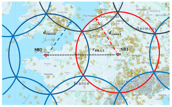
Figure 3.
Cellular SB network for aviation.
Figure 4 displays the variation of the inter-SB distance with the aircraft height at different values of ground elevation angles. The value of can be chosen as zero for regions where the aircraft is unlikely to land or takeoff such as over regions where oceans, wide deserts or forests exist, and in this case, the inter-SB distance can be extended to 1500 km for aircraft flying at 11 km cruise altitude. However, for aircraft security, control, and continued connection, it is recommended that the minimum elevation angle is greater than zero even over rural areas to achieve an acceptable quality of communication between aircraft and SB.
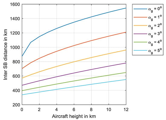
Figure 4.
Variation of inter-SB distance with the aircraft height at different minimum elevation angles.
On the other hand, the practical value of the inter-SB distance is smaller than that given in Equation (13) to reduce the atmospheric losses resulting from the Earth’s atmospheric gases over the path between SB and aircraft. This problem arises near the end-of-coverage regions where the signal propagates through longer distances in the atmosphere. Also, the impact of weather conditions is severe during heavy rain or in the presence of taller clouds and high-humidity atmosphere which provide higher attenuation than other clear-sky regions. A detailed discussion of atmospheric losses will be presented and modelled in the next section.
For a cellular hexagonal SB-aeronautical system, a single SB has an area of coverage that can be determined by a hexagon of side length that is equal to and the area of the aerial cell is, therefore, given by:
Figure 5 displays the variation of the SB cell coverage area in square kilometers with the aircraft height for SB located 20 km high. The area of a single SB may cover an area up to 1.5 million square kilometers for an aeronautical communication network which may extend over many countries.
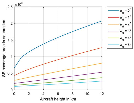
Figure 5.
Variation of SB coverage area with the aircraft height at different minimum elevation angles.
6. Atmospheric Gaseous Losses Profile for Aircraft–Stratospheric Basestation (SB) Link
The communication channel between SB and aircraft is affected by three main regions according to the aircraft altitude and the elevation angle to SB. Figure 6 demonstrates these three flight regions or stages where the atmospheric absorption in the troposphere has a considerable impact at the coverage boundary between neighbored SBs and during the climbing and descending periods, while the most efficient communication channel performance is expected when the aircraft is at full height in the cruise stage and not near the SB coverage boundary.
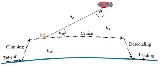
Figure 6.
A complete aircraft flight profile model.
The atmospheric absorption increases when the signal passes in longer paths in the troposphere where atmospheric gases, clouds, rain, fog, and other factors impact the signal propagation by absorbing its energy [25,26,27,28,29]. Fortunately, the aircraft is temporarily flying at low altitudes such as during takeoff or landing and also during overlapping regions of neighbouring SBs, therefore, it is expected that most of the time it receives high performance communication with the SB as it will be above clouds during cruise stage.
The clear sky between aircraft and SB and the much lower communication range compared to the lowest-altitude of 340 km satellite systems [9] make a SB cellular network as an ideal solution for the provision of broadband services during flight and improves the efficiency of aircraft monitoring. Therefore, the signal loss due to atmospheric attenuation is analyzed during the complete flight duration in this section. A simple model for the flight stages is shown in Figure 7 where the slant distance between SB and aircraft passes mainly in the troposphere and stratosphere layers. Most of the atmospheric gases and water vapor exist in the troposphere and their densities are decreased largely in the stratosphere. As a proof of concept and for investigation purposes, we may apply the simple formulas of the International Telecommunication Union (ITU) recommendations, so according to the ITU radio recommendation No.676-10 [27], the atmospheric attenuation is due to the absorption of signal energy by atmospheric gases, mainly Oxygen and water vapor. Most of the designated frequencies for 5G services and networks are ranging from 3.5 GHz up to 66 GHz [30]. The carrier frequencies are organized in two sets namely FR1 and FR2 where FR1 frequencies are sub 6 GHz while FR2 are above 6 GHz [17]. In this paper, we will modify these two sets to include 3.5, 6, and 10 GHz in FR’1 while FR’2 includes 26, 28, 40, 50 and 66 GHz. At these mm-wave frequencies, the atmospheric attenuation changes drastically especially at the higher frequencies [4]. For the aircraft–SB cellular network, the flight profile will be expected to have different attenuation levels as the signal passes through different tropospheric layers’ thicknesses. One related methodology for atmospheric attenuation calculations in the ITU recommendations in [27] considers only the atmospheric path loss for elevated stations below 10 km altitude which is not suitable for the aircraft–SB network. Therefore, in this section, we will extend this model to calculate the atmospheric attenuation that fits the proposed system based on the numerical methodology in [27] for slant paths. Assuming that the atmospheric slant range between an aircraft and SB can be divided into very small thickness layers where in the nth layer, the signal has a path segment along the aircraft–SB line of sight as shown in Figure 7 with an incident angle with the (n + 1)th layer, the refraction angle of the nth layer is , and the new elevation angle of the (n + 1)th layer is . According to the layer altitude, the atmospheric parameters such as pressure and temperature change correspondingly, and hence each layer has its own refractive index which will determine the values of , , and .
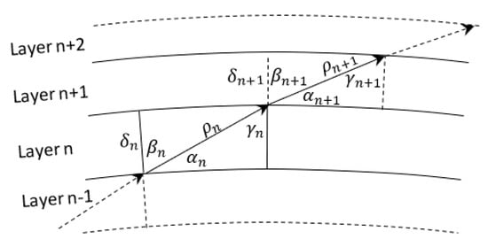
Figure 7.
Layered air model for atmospheric attenuation calculation [13].
Therefore, for aircraft–SB communications link, the overall atmospheric attenuation, , can be written by:
where and are the Oxygen and water vapor specific gaseous attenuation in dB/km respectively. The nth layer thickness, , can be calculated according to the following equation [27]:
Figure 8 displays the layer thickness variation with n along with the altitude of the segment. This figure is useful for determining the range of values for n between the aircraft and SB as will be explained below.
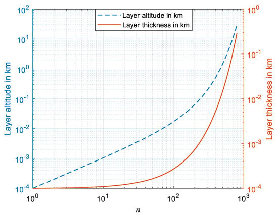
Figure 8.
Atmospheric layer altitude and thickness variation with layer number.
If we start with given by:
then, we can calculate the incidence and refraction angles using Snell’s Law in polar form as follows:
and,
The corresponding nth layer path segment can be calculated using the following formula [27]:
where is the radial distance from the Earth’s center to the bottom boundary of the nth layer and is the refractive index of the nth layer.
The layer thicknesses in Equation (16) are used to calculate the atmospheric path loss of the whole atmosphere as suggested in [14], however, for the aircraft–SB communication link, the signal passes through specific slant range that will not span all the atmosphere and the therefore not all the steps provided in Equation (16) will be used. For example, to reach an altitude of 100 km, the value of N should be 992, while the link stops at the SB height at approximately 20 km. Also, the starting step at which n = 1 is used only when the aircraft is on the ground level. Denoting the starting value of n by at an aircraft altitude should achieve the following equation:
For SB, it will be , which is found by achieving the following equation:
Then, the slant path atmospheric attenuation between aircraft and SB can be calculated from the following equation:
Therefore, each segment has its corresponding specific atmospheric attenuation and length, and the overall atmospheric attenuation can be calculated using Equation (23). According to the link path between an aircraft and SB, there are two main scenarios that could be followed as discussed in the following sections.
6.1. Complete Flight Profile Scenario
In this communication scenario, an aircraft has the complete flight stages as shown in Figure 6. From takeoff to landing in a complete flight, the aircraft passes three main stages including climbing, cruise and descending. A typical civil flight has cruise altitudes ranging from 33,000 to 40,000 ft (10–12 km) high. The climbing and descending ground distance ranges from 100 to 250 km according to the cruise height. Figure 9 demonstrates the flight geometry model during the three phases where the ground elevation angle is at the airport. The flight starts/ends at a distance and the aircraft reaches the cruise height at an elevation angle . In the climbing/descending stage, the aircraft has an altitude and elevation angle . Assuming also that the climbing/descending inclination angle is , then the ground distances measured from an airport during takeoff and climbing/descending stages are obtained as follows respectively:
and,
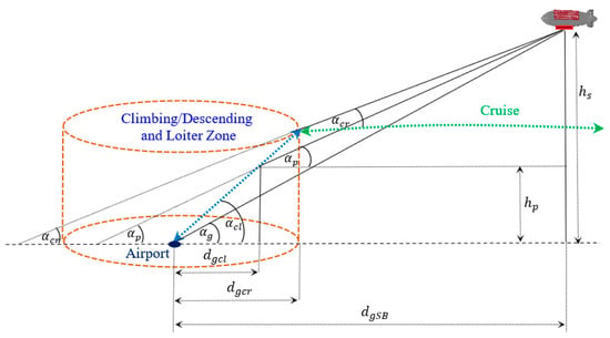
Figure 9.
Geometrical model for calculation of atmospheric attenuation profile during flight.
Also, the starting cruise elevation angle is given by:
where during cruise stage, the cruise elevation angle is given by:
The atmospheric losses will vary with the aircraft height where it is expected to have lower losses in the cruise stage while severe losses impact the communication performance during the climbing/descending periods. Fortunately, for passengers during climbing/descending periods, it is not allowed to engage in activities and they must stay fastened. The most active period of broadband services will, therefore, during cruise stage.
The flowchart shown in Figure 10 can be followed when we calculate the atmospheric gaseous attenuation. The main factors affecting this attenuation is the aircraft altitude and the elevation angles which define the atmospheric thickness in the troposphere which affects the communication link. The impact of frequency on the atmospheric attenuation is described for each set of frequencies (i.e., FR’1 and FR’2) where there is an expected big difference in performance between the two sets. As a case study to investigate the atmospheric losses for this scenario, assume that the which results in ground distance of approximately 508 km between the aircraft and SB. If the climbing/descending ground distance is assumed to be 200 km and the cruise height is 11 km, then the resulting flight atmospheric attenuation profile is displayed for the set of FR’1 frequencies (i.e., @ 3.5, 6, and 10 GHz) in Figure 11a. The effect of atmospheric attenuation especially during the cruise stage is less than 0.1 dB at f = 10 GHz which is negligible compared to a maximum of 2 dB loss during the takeoff stage at the same frequency. This is because at cruise heights, the aircraft is almost above the troposphere where the air density and temperature provide very low atmospheric attenuation and the three frequency attenuation curves converge to the same values indicating almost frequency-independent atmospheric attenuation in this frequency range. At the minimum distance between aircraft and SB, where the SB is at the zenith position of the aircraft, the atmospheric attenuation is very small and can be neglected.
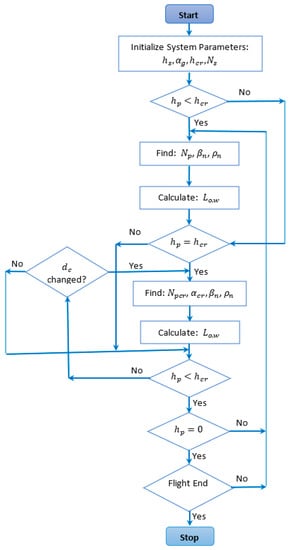
Figure 10.
Atmospheric attenuation calculation flowchart during flight.
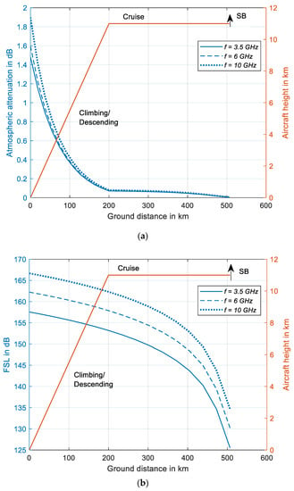
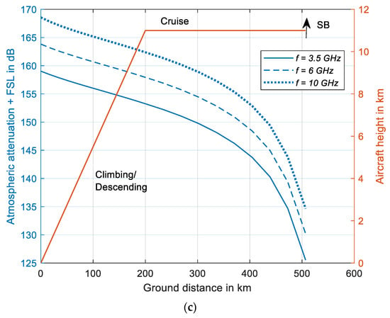
Figure 11.
Flight signal attenuation performance for 5G frequencies up to 10 GHz in dB: (a) atmospheric gaseous attenuation, (b) free-space loss (FSL), (c) combined atmospheric gaseous attenuation and FSL performance.
The atmospheric attenuation is added to the free space path loss which is given by:
where f is the signal frequency and c is the speed of light. L can be expressed in dB as follows:
where is the communication range in km and is the carrier frequency in GHz. The path loss is displayed in Figure 11b and the total signal loss (atmospheric plus free space path losses) is shown in Figure 11c where the impact of path loss on the transmitted signal is dominant. Therefore, for FR’1 frequencies, the broadband aircraft–SB aeronautical network is mainly affected by the free-space path loss rather than atmospheric absorption losses.
The same demonstrations for the FR’2 higher set of mmWave frequencies are shown in Figure 12a–c and Figure 13 including atmospheric gaseous attenuation only, FSL, and the combined attenuation of both, respectively. As shown in Figure 12a, the atmospheric attenuation at 26 and 28 GHz are almost of the same profile with aircraft altitude and ground distance. However, higher atmospheric losses affect greatly the other higher frequencies (i.e., above 40 GHz), especially during the climbing/descending stage, while the losses drop to very low levels at the cruise heights with converging performance indicating low dependency of atmospheric losses at this height. In Figure 12b, the FSL variations are shown for FR’2 frequencies while the combined atmospheric attenuation and FSL is shown in Figure 12c where the higher impact of atmospheric attenuation appears clearly during climbing/descending stages. On the other hand, at cruise levels, the FSL is the dominant attenuation factor.
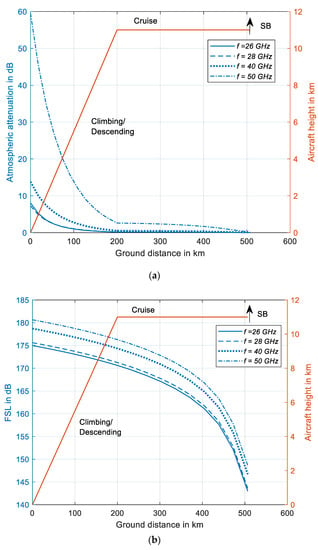
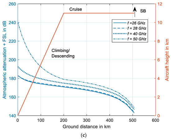
Figure 12.
Flight signal attenuation performance for 5G mm-wave frequencies from 26 up to 50 GHz in dB: (a) atmospheric gaseous attenuation, (b) free-space loss (FSL), (c) combined atmospheric gaseous attenuation and FSL performance.
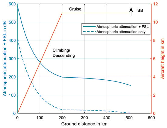
Figure 13.
Flight signal attenuation performance at 66 GHz 5G mm-wave frequency.
As shown in Figure 13, at the 66 GHz mmWave frequency, the atmospheric attenuation is very high and it is not feasible at all to use during the climbing/descending stage, while it does not exceed 20 dB at the cruise height.
6.2. Long Flight Handover Scenarios
As shown in the previous section, the impact of atmospheric losses is very high near ground especially at higher frequencies, while it becomes insignificant at the cruise altitudes. For long flight distances, handover should be performed between aircraft and neighbouring SBs. The inter-SB distance is determined according to the level of received signals at the aircraft. Long flights stay at the cruise level most of the time, however the spherical surface of the Earth means that, over the horizon, the line-of-sight between an aircraft and SB will be inserted into the troposphere again and is subjected to higher atmospheric attenuation. The situation becomes more complicated if the troposphere contains clouds/fog along this path which means a huge signal attenuation may occur especially at high mm-wave frequencies. This scenario is shown in Figure 14, where the line-of-sight between an aircraft and SB at which a handover may be performed lies between two limits and .
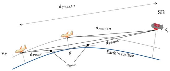
Figure 14.
Geometry for handover scenarios in SB network for aviation.
A compromise between the inter-SB distance and the acceptable minimum signal level at the aircraft should be performed to reduce the number of SBs in the network while providing acceptable communication performance. The best communication performance can be achieved when the handover is performed at a cruise distance where the aircraft is at the tangential point to the circular path of altitude , a point under which the minimum elevation angle exits on the ground. This scenario leads to denser SB network where the number of required SBs is the largest. On the other hand, the worst communication performance is obtained at a handover distance at which the line-of-sight is almost tangential to the Earth’s surface which corresponds to paths at minimum elevation angles as shown in Figure 14. If the line-of-sight becomes closer to the Earth surface than , severe blocking will occur, and the link will be eventually lost. The atmospheric attenuation at distances close to can be calculated by splitting the path between an aircraft and SB into two main segments; one from ground point “g” to the aircraft and the other from this point to the SB or:
The overall path atmospheric attenuation will be the sum of the two atmospheric attenuations exhibited in the two segments or:
This equation is expected to give a little bit overestimation for the atmospheric attenuation due to the approximation of as the sum of the two segments between ground and both aircraft and SB. However, it gives a good estimation at an elevation angle that is equal to zero where is exactly equal to the sum of and .
If the flight is spanning very long distance over areas with no airports such as wide desert or oceans, the communication slant range may be extended to its maximum allowable value in order to reduce the required number of SBs in the network provided that it does not affect seriously the communication performance especially the atmospheric losses. As shown in Figure 15, the aircraft at the maximum line-of-sight distance, the signal will be exposed to denser atmosphere and hence more atmospheric attenuation. The atmospheric attenuation at is approximately double the value at due to the re-insertion of the line-of-sight into the troposphere.
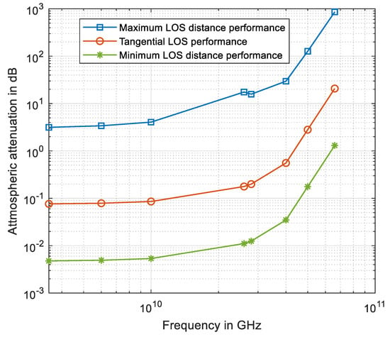
Figure 15.
Atmospheric gaseous attenuation for three different handover scenarios.
The minimum atmospheric attenuation exists when the aircraft is directly underneath the SB where the atmospheric layer thickness is minimum between them. The performance of this case is shown in Figure 15 as the minimum line-of-sight (LOS) distance performance. Figure 15 shows a huge dynamic range of signal attenuation between an aircraft and SB especially at high frequencies for the case of maximum LOS distance between SBs. The dynamic range is very important as it defines the requirements of the receiver and transmitter circuits for proper signal reception and affects the power control and consumption of the aircraft.
Table 1 displays the signal dynamic range due to atmospheric attenuation only at the operating 5G frequencies. The performance of tangential LOS handover is acceptable even at high frequencies where the dynamic range in this case is only 2.634 dB at 50 GHz and increases to 19.454 dB at 66 GHz. However, the dynamic range of atmospheric attenuation is very small at lower frequencies where it is only 0.522 dB at 40 GHz and is negligible at 28 GHz and lower frequencies. On the other hand, a special care for applying handover at maximum LOS link distance should be performed especially at high frequencies greater than 40 GHz. The handover process is impossible at maximum LOS case for the 50 and 66 GHz where the dynamic range is very large due to the huge atmospheric attenuation which is more than 110 dB. The other lower frequencies could be used for SB networks performing handover at the maximum LOS distance.

Table 1.
Signal dynamic ranges due to atmospheric gaseous attenuation only for SB @ 20 km high and cruise altitude of 11 km high.
7. Other Temporary Atmospheric Attenuation Factors
Although gaseous absorption is the most dominant impacting factor for signal transmission, other atmospheric factors provide severe signal attenuation such as rains, clouds, and fog. The occurrence of these tropospheric phenomena depends on the regional and seasonal climatic characteristics where rainy and humid regions suffer from these factors most of the year [26]. The rain rate, signal frequency, along with the path length of the signal passing through rain all determine the rain attenuation as recommended by ITU-R P.838-3 [28] which will be used for simple calculations in this paper, while other rain attenuation models can be also applied [26]. For a stratospheric 5G aircraft network, frequencies below 10 GHz suffer slightly at light and moderate rain conditions as shown in Figure 16 for an aircraft located at the airport and communicating with SB. The curves in this figure assume a worst case of 300 km length of the rainy region that the signal passes through. At 6 GHz, the very heavy rain conditions result in 4.4 dB loss while at 10 GHz it becomes as high as 21.7 dB. For frequencies above 10 GHz, the rain attenuation becomes very impacting which almost results in signal loss especially at very high frequencies. Only light rain conditions can be tolerable while other rain rates almost shadow the signal with more than 100 dB loss at frequencies above 30 GHz during very heavy rain conditions. For a network of SB with handover operation, an aircraft–SB maximum LOS passes through the troposphere and the rain path may be 500 km long. The rain attenuation performance for this case is shown in Figure 17 where a higher attenuation occurs, especially at higher frequencies.
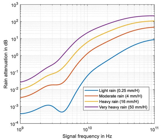
Figure 16.
Airport maximum rain attenuation for aircraft–SB communication.
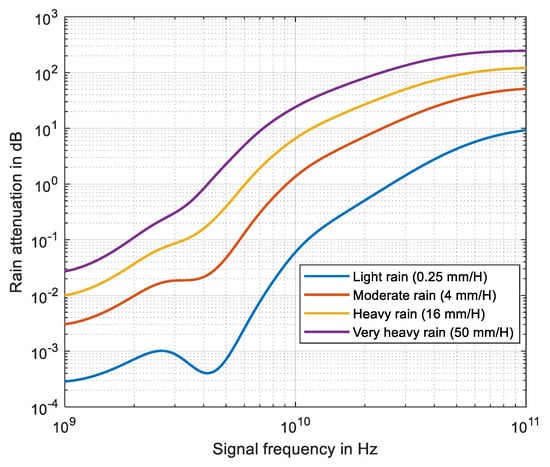
Figure 17.
Rain attenuation at maximum aircraft–SB LOS distance communication.
The other main affecting temporary factor is the fog/cloud attenuation. This attenuation is insignificant for frequencies below 10 GHz. However, as a worst case, the clouds and fog may be extended over the whole horizon from the aircraft towards SB during airport-climbing/descending phases and maximum LOS distance such as in tropical regions or over oceans near equator circle. The air temperature and the cloud water density along with the communication distance will determine the fog/cloud attenuation according to the ITU recommendations ITU-R P.840-8 [29]. As the LOS from an aircraft to SB passes through different tropospheric layers, then the temperature profile should be inserted in the fog/cloud attenuation equation for accurate calculation.
As most cloud peaks do not increase more than 12 km, then the total fog/cloud attenuation,, in dB can be given by:
where is the fog/cloud specific attenuation in dB/km [29] and is the nth air layer length generated by Equation (20) with layer thickness calculated from Equation (16) and the upper limit of n is 710 calculated to achieve the total height of 12 km as follows:
The atmospheric temperature of the nth layer used in the calculation of can be given by:
where is the height of the nth layer in km and can be calculated as from the following summation:
The fog/cloud attenuation performance with frequency is shown in Figure 18 where approximately 13 dB of minimum attenuation level occur at 10 GHz for an aircraft located at the airport and increases to approximately 32 dB for the maximum LOS case. Severe fog/cloud attenuation occurs at higher frequencies which indicate a total loss of the communication link at these frequencies. For example, at 28 GHz, the loss will be approximately 80 dB for airport communication while it increases to 200 dB for maximum LOS communication.
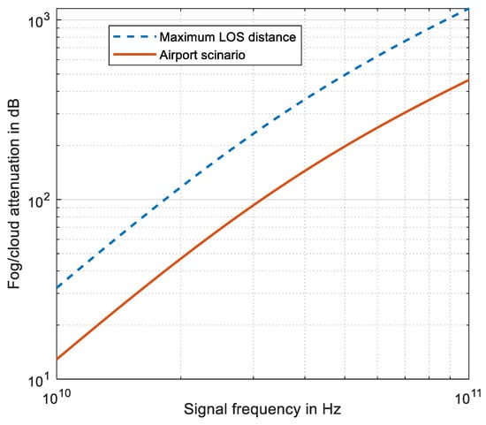
Figure 18.
Fog/cloud attenuation in dB for two aircraft–SB communication scenarios.
8. System Feasibility Discussion
8.1. Feasibility of the Aircraft–SB System for Tropospheric Flights
In the previous sections, the main affecting factors on an aircraft–SB communication are demonstrated with numerical results that could help judge the feasibility of 5G and beyond network operating frequencies and services provision during flight. For flights of heights falling below 10 km in the troposphere, the impact of permanent gaseous attenuation on the signal’s transmission appears clearly in the mm-wave frequency bands greater 28 GHz. 5G frequencies below 10 GHz have acceptable performance even at maximum LOS handover scenario as shown previously in Table 1. However, the gaseous attenuation has severe levels on the signals of frequencies greater than 26 GHz where starting communications using these frequencies at airport is not feasible even at clear dry sky with no fog, clouds, and rains. At heights below 10 km (troposphere height), we may use only frequencies below 10 GHz, or at most 26/28 GHz, in clear sky conditions with an extra 8 dB margin in the link budget. Other higher frequencies are exposed to high atmospheric absorption with almost impossible communication at 50 and 66 GHz frequencies even at clear sky conditions or regions. On the other hand, humid regions that are continuously exposed to heavy rain and fog/cloud occurrence, suffer from extra severe attenuation during the occurrence of these weather phenomena especially at frequencies above 10 GHz. Therefore, for regions with high availability of rain, fog/cloud occurrence, the feasible 5G frequency bands for tropospheric flights fall below 10 GHz even at heavy rain conditions and at the maximum LOS handover scenario with an extra few dB in the link budget below 10 GHz. However, at 10 GHz, the fog/cloud attenuation adds extra 32 dB along with possible 26 dB of very heavy rain attenuation may totally block the communication below tropopause heights for flights. At frequencies above 10 GHz, the rain and fog/cloud losses result in unstable communication between an aircraft and SB starting at the airport or near ground heights.
8.2. Feasibility of the Aircraft–SB System for Flights above or near Tropopause Height
As most of the atmospheric losses occur in the troposphere, communication between an aircraft and SB above tropopause level seems very attractive and feasible even at 5G mm-wave frequencies above 26 GHz. Cloud heights are rarely extended above 12 km heights and therefore, fog/cloud and rain losses do not exist, and the only dominant losses are the FSL and atmospheric gaseous attenuation. According to the data shown in Figure 13, a maximum atmospheric gaseous attenuation of about 20 dB for the 66 GHz frequency is expected for an aircraft performing tangential handover at 11 km high where the LOS distance is approximately 520 km between the aircraft and SB. Below 66 GHz and for the same tangential LOS handover scenario, all frequencies are subjected to very low gaseous attenuation where it is only of maximum 3 dB at 50 GHz which is reduced to less than 1 dB for the other lower frequencies. However, for the maximum LOS handover scenario, large gaseous attenuation occurs for frequencies above 40 GHz due to the re-insertion of the LOS path into the troposphere. Therefore, the system could be feasible and applicable at the new mm-wave frequencies of the 5G systems subjected to the flight altitude above the tropopause height during cruise and the handover is performed at the tangential LOS case. One major advantage of operating the 5G frequencies at these heights only is reduced interference with the future terrestrial 5G networks wave bands where the troposphere in this case provides an attenuation barrier between the aircraft–SB network and terrestrial 5G networks especially for frequencies above 40 GHz where the gaseous loss is very high. In addition, an aircraft could be served at low altitudes with terrestrial networks initially while near cruise levels, a vertical handover between the terrestrial 5G networks and the 5G SB aerial network could be performed to gain more bandwidth and provide higher bit rate services to onboard passengers during flight.
8.3. Feasibility of the Aircraft–SB System Compared with Aircraft–Satellite Systems
Conventional mobile satellite systems are the main source of internet services for aviation and maritime. The low-orbit (LEO) satellites are considered feasible systems for mobile-satellite communications compared with geostationary (GEO) satellites. However, the low orbital altitudes of the LEO satellites provide low orbital periodic time and hence short visible time duration for airborne or maritime stations and requires frequent handover. For example, the most recently high-speed Internet Starlink satellites [8] orbit at altitude of 550 km in inclined orbits where each has about 66 satellites. Each satellite in this system can be visible for a few minutes and the ground receiving stations must perform handover to another nearby visible satellite. On the other hand, moving transceivers result in Doppler frequency shift which is directly proportional to the relative speed between transceivers. LEO satellites have very high orbital speed which if its direction is opposite to the aircraft will result in higher Doppler shifts. The communication performance is expected to be improved in “GeoSurf” constellation proposed in [11] where zenith paths are considered for the communication link, so the atmospheric losses and FSL are reduced compared to other LEO constellations. However, an aircraft–SB system provides many advantages and become more feasible compared to most mobile-satellite systems. For example, SB is kept fixed in position and there is no self-initiated handover or Doppler frequency shift. A single SB at 20 km high can serve an aircraft for about a distance of 1200 km or more during flight. If the average aircraft speed is 800 km/h, this means that the aircraft can be served by a single SB for approximately 90 min without any required handover during cruise. The Doppler frequency shift in an aircraft–SB network is only initiated by the aircraft movement and, therefore, may be predicted and manipulated. Also, the SB can be easily managed, controlled, and maintained compared with LEO satellites as SBs can be positioned and adapted to the coverage regions where aircraft always pass and can be landed for maintenance and upgrading.
On the other hand, as the SB is located at lower altitudes than any broadband mobile satellite, therefore, the propagation delay is expected to be lower in SB networks than satellites. The signal propagation delay, , is given by:
where is the speed of light.
Figure 19 displays the variation of the maximum propagation delay with the basestation altitude which can be considered as SB or mobile satellite. The small squares on the curves corresponds to the delay at the altitudes of current Starlink satellites while the small circles correspond to the SB altitude which is 20 km. The data in this figure show that the SB systems can provide less propagation delay compared to LEO satellites especially for satellite altitudes greater than 550 km. If the minimum elevation angle is 10°, then the SB network will always provide less of a propagation delay compared to Starlink satellites at any altitude. In addition to the improved propagation delay in aircraft–SB networks, the FSL is also improved compared to LEO mobile satellites. Table 2 summarizes the feasibility comparison between an aircraft–SB system and an aircraft–mobile–satellite system.
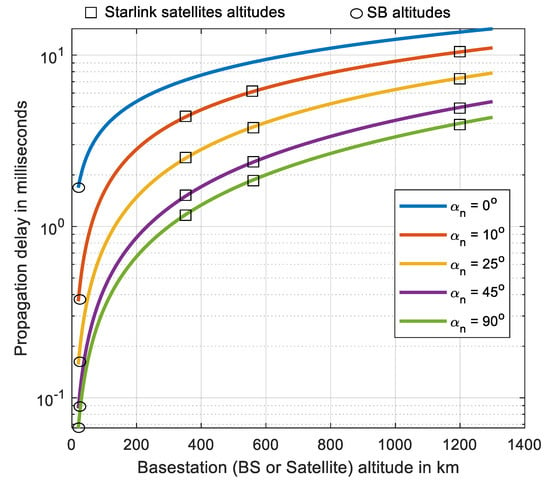
Figure 19.
Propagation delay variation with basestation altitude at different minimum elevation angles.

Table 2.
Comparison between aircraft–SB and aircraft–Starlink satellite networks.
Table 3 compares between the FSL of the aircraft–SB link and the aircraft-LEO mobile satellite one. At the same elevation angle, the aircraft–SB link always has less FSL. For example, the minimum elevation angle of 25° for Starlink satellites at 340 km provides more FSL of at least 23.8 dB compared to an aircraft–SB link. The link of the aircrafts that make handover at the tangential tropopause height in SB network are subjected also to less FSL by at least 3.4 dB which increases to 13 dB compared to the FSL of Starlink satellites at 1200 km altitude.

Table 3.
Free-space loss (FSL) at different operating frequencies for aircraft–SB and aircraft–Starlink satellite links.
9. Conclusions
In this paper, an efficient communication network for civil aviation aircraft has been proposed where a stratospheric platform basestation (SB) located at 20 km high in the stratosphere is used to provide a high-speed Internet connection for aircraft during flights. The system architecture and geometrical aspects have been demonstrated and analyzed where the communication range between aircraft and SB has been deduced with its coverage area. To provide efficient 5G and beyond services at mm-waves from SB to aircrafts, the system performance has been analyzed and investigated at frequencies ranging from 3.5 to 66 GHz in terms of the most influential parameters which are the losses caused by such factors as atmospheric gaseous absorption, rain, and fog/cloud. In this investigation, a flight model has been proposed which demonstrated the performance in three distinct flight stages which are take-off/landing, climbing/descending, and cruise stages. A feasibility study based on the three atmospheric loss performances has shown that an efficient and improved signal levels at mm-wave frequencies above 40 GHz can be achieved during cruise stage only, which presents a flight time especially for long flights of several hours duration while lower frequencies could be used during the other flight stages especially at those frequencies below 10 GHz. On the other hand, the proposed aircraft–SB network has been compared with the current and future mobile-satellite systems such as Starlink satellites where the proposed SB-based network provides lower latency and atmospheric attenuation, longer aircraft–SB link duration, and relatively low handover rate. In future work, the communication link between aircraft and SB will be improved by using adaptive beamforming techniques onboard both aircraft and SB to mitigate atmospheric losses and enhance the system capacity.
Funding
Taif University Researchers Supporting Project number (TURSP-2020/161), Taif University, Taif, Saudi Arabia.
Conflicts of Interest
The authors declare no conflict of interest.
References
- Available online: https://aviationbenefits.org/ (accessed on 28 August 2020).
- Available online: https://www.icao.int/safety/acp/acpwgf/acp-wg-s-web%20meeting%205/acp-wg-s_wp02%20definitions%20of%20various%20aircraft%20domains.docx (accessed on 28 August 2020).
- Morgado, A.; Huq, K.M.S.; Mumtaz, S.; Rodriguez, J. A survey of 5G technologies: Regulatory, standardization and industrial perspectives. Digit. Commun. Netw. 2018, 4, 87–97. [Google Scholar] [CrossRef]
- Uwaechia, A.N.; Mahyuddin, N.M. A Comprehensive Survey on Millimeter Wave Communications for Fifth-Generation Wireless Networks: Feasibility and Challenges. IEEE Access 2020, 8, 62367–62414. [Google Scholar] [CrossRef]
- Qamar, F.; Siddiqui, M.U.A.; Hindia, M.N.; Hassan, R.; Nguyen, Q.N. Issues, Challenges, and Research Trends in Spectrum Management: A Comprehensive Overview and New Vision for Designing 6G Networks. Electronics 2020, 9, 1416. [Google Scholar] [CrossRef]
- Available online: https://aerospace.honeywell.com/en/learn/products/satellite-communications (accessed on 28 August 2020).
- Available online: https://www.inmarsat.com/aviation (accessed on 28 August 2020).
- Available online: https://www.starlink.com/ (accessed on 28 August 2020).
- Available online: https://www.oneweb.world/ (accessed on 28 August 2020).
- Arum, S.C.; Grace, D.; Mitchell, P.D. A review of wireless communication using high-altitude platforms for extended coverage and capacity. Comput. Commun. 2020, 157, 232–256. [Google Scholar] [CrossRef]
- Matricciani, E. Geocentric Spherical Surfaces Emulating the Geostationary Orbit at Any Latitude with Zenith Links. Futur. Internet 2020, 12, 16. [Google Scholar] [CrossRef]
- Botsinis, P.; Alanis, D.; Xu, C.; Babar, Z.; Chandra, D.; Ng, S.X.; Hanzo, L. Air-to-Ground NOMA Systems for the “Internet-Above-the-Clouds. ” IEEE Access 2018, 6, 47442–47460. [Google Scholar] [CrossRef]
- Raja, M. Application of cognitive radio and interference cancellation in the L-Band based on future air-to-ground communication systems. Digit. Commun. Netw. 2019, 5, 111–120. [Google Scholar] [CrossRef]
- Yan, C.; Fu, L.; Zhang, J.; Wang, J. A Comprehensive Survey on UAV Communication Channel Modeling. IEEE Access 2019, 7, 107769–107792. [Google Scholar] [CrossRef]
- Zhao, Y.; Zuo, X.; Shang, Y.; Mu, X.; Zhang, J. Prior-Information Associated Channel Parameter Estimation for Aeronautical Communications. In Proceedings of the 2018 International Conference on Cyber-Enabled Distributed Computing and Knowledge Discovery (CyberC), Zhengzhou, China, 18–20 October 2018; pp. 401–4014. [Google Scholar] [CrossRef]
- Schneckenburger, N.; Jost, T.; Walter, M.; Del Galdo, G.; Matolak, D.W.; Fiebig, U.-C. Wideband Air–Ground Channel Model for a Regional Airport Environment. IEEE Trans. Veh. Technol. 2019, 68, 6243–6256. [Google Scholar] [CrossRef]
- Bellido-Manganell, M.A.; Gräupl, T.; Schnell, M. Impact Assessment of the L-Band Digital Aeronautical Communications System on the Joint Tactical Information Distribution System. IEEE Trans. Veh. Technol. 2019, 68, 3629–3641. [Google Scholar] [CrossRef]
- Mäurer, N.; Bilzhause, A. A Cybersecurity Architecture for the L-band Digital Aeronautical Communications System (LDACS). In Proceedings of the 2018 IEEE/AIAA 37th Digital Avionics Systems Conference (DASC), London, UK, 23–27 September 2018; pp. 1–10. [Google Scholar] [CrossRef]
- Luo, Q.; Wang, J. FRUDP: A Reliable Data Transport Protocol for Aeronautical Ad Hoc Networks. IEEE J. Sel. Areas Commun. 2018, 36, 257–267. [Google Scholar] [CrossRef]
- Luo, Q.; Wang, J.; Liu, S. AeroMRP: A Multipath Reliable Transport Protocol for Aeronautical Ad Hoc Networks. IEEE Internet Things J. 2019, 6, 3399–3410. [Google Scholar] [CrossRef]
- Zhang, J.; Chen, T.; Zhong, S.; Wang, J.; Zhang, W.; Zuo, X.; Maunder, R.G.; Hanzo, L. Aeronautical Ad Hoc Networking for the Internet-Above-the-Clouds. Proc. IEEE 2019, 107, 868–911. [Google Scholar] [CrossRef]
- Luo, Q.; Wang, J. Multiple QoS Parameters-Based Routing for Civil Aeronautical Ad Hoc Networks. IEEE Internet Things J. 2017, 4, 804–814. [Google Scholar] [CrossRef]
- Büchter, K. Availability of aeronautical ad-hoc network in different global air transport fleet scenarios. In Proceedings of the XXXIInd General Assembly and Scientific Symposium of the International Union of Radio Science (URSI GASS), Montreal, QC, Canada, 19–26 August 2017; pp. 1–4. [Google Scholar] [CrossRef]
- Dessouky, M.I.; Sharshar, H.A.; Albagory, Y.A. Design of High Altitude Platforms Cellular Communications. Prog. Electromagn. Res. 2007, 67, 251–261. [Google Scholar] [CrossRef]
- Han, C.; Duan, S. Impact of Atmospheric Parameters on the Propagated Signal Power of Millimeter-Wave Bands Based on Real Measurement Data. IEEE Access 2019, 7, 113626–113641. [Google Scholar] [CrossRef]
- Matricciani, E. Space communications with variable elevation angle faded by rain: Radio links to the Sun-Earth first Lagrangian point L1. Int. J. Satell. Commun. Netw. 2016, 34, 809–831. [Google Scholar] [CrossRef][Green Version]
- Radio Communication Sector of International Telecommunication Union. Attenuation by Atmospheric Gases and Related Effects; Document ITU-R P. 676-10; ITU: Geneva, Switzerland, 2019. [Google Scholar]
- Radio Communication Sector of International Telecommunication Union. Specific Attenuation Model for Rain for Use in Prediction Methods; Document ITU-R P. 838-3; ITU: Geneva, Switzerland, 2005. [Google Scholar]
- Radio Communication Sector of International Telecommunication Union. Attenuation Due to Clouds and Fog; Document ITU-R P. 840-8; ITU: Geneva, Switzerland, 2019. [Google Scholar]
- 3GPP. NR—Study on Test Methods; TR 38.810 V2.0.0; 3GPP: Valbonne, France, 2018. [Google Scholar]
Publisher’s Note: MDPI stays neutral with regard to jurisdictional claims in published maps and institutional affiliations. |
© 2020 by the author. Licensee MDPI, Basel, Switzerland. This article is an open access article distributed under the terms and conditions of the Creative Commons Attribution (CC BY) license (http://creativecommons.org/licenses/by/4.0/).