Article

Chebyshev-Response Branch-Line Couplers with Enhanced Bandwidth and Arbitrary Coupling Level

by
Robert Smolarz
*,
Krzysztof Wincza
and
Slawomir Gruszczynski
Department of Electronics, AGH University of Science and Technology, 30-059 Krakow, Poland
*
Author to whom correspondence should be addressed.
Electronics 2020, 9(11), 1828; https://doi.org/10.3390/electronics9111828
Submission received: 15 October 2020 / Revised: 27 October 2020 / Accepted: 28 October 2020 / Published: 2 November 2020
(This article belongs to the Special Issue RF/Mm-Wave Circuits Design and Applications)

Abstract

:
A new approach to the synthesis of broadband branch-line couplers with arbitrary coupling level was investigated in this paper. It was shown that the operational bandwidth of a classic branch-line coupler can be increased by utilizing N-section impedance transformers added to each of the coupler’s ports. Furthermore, the obtained response can be approximated by the Chebyshev polynomial. Moreover, it was proven that for such couplers a range of coupling coefficient values can be obtained by the modification of classic branch-line topology. The analysis of the electrical parameters of the proposed branch-line couplers was comprehensively investigated. To verify the correctness of the proposed design procedures, 3-dB, and 6-dB broadband branch-line couplers operating at the center frequency of 2 GHz having return losses greater than 20 dB were designed, fabricated, and measured.

1. Introduction

Directional couplers are popular and commonly used components in microwave electronics. A significant number of known solutions is based on coupled-line sections [1,2,3]. However, to achieve relatively strong coupling in a symmetric coupled-line section, the distance between the lines must be relatively small, thus, multi-layer substrate configurations like the broadside-coupled stripline technique are often considered [4,5]. Otherwise, tandem [6,7] or Lange [8,9] configurations may be taken into account.
Alternatively, rat-race, and branch-line couplers can be successfully implemented in the microstrip technique due to the simplicity of their circuit topologies. Such circuits can be found in planar applications in both PCB technology [10,11] and in MMIC [12]. Due to the fact that such couplers feature narrow bandwidth, their applicability is limited. To enhance the operational bandwidth novel rat-race coupler’s topologies have been proposed, where a classic 270°-long transmission line section is replaced by a shorted-coupled-line section [13], which in turn, can complicate the fabrication process. Thus, methods of enhancing operational bandwidths are still the subject of research. One of the widely known concepts of broadband branch-line couplers is an N-section branch-line coupler [14,15]. The bandwidths of such couplers can be significantly increased at the expense of increasing their total size. In [16,17] the authors reported that additional quarter wave sections connected to each of branch-line ports can be used to achieve broadband response. However, the proposed design methodologies are focused on the analysis of a single quarter-wave section’s cases.
Apart from the broadband operational bandwidth of branch-line couplers, their second crucial parameter is the coupling coefficient, which can be related directly to a power division between output ports. To achieve the desired coupling coefficient a structure consisting a phase inverter has been proposed in [18]. Moreover, in [19] the authors noticed that changes of electrical lengths of transmission-lines also influence the coupling. Other methods are focused on adding series stubs, together with modifications of the transmission-line impedances of both the quarter-wave sections and branch-line rings [20,21,22].
In this paper, a new approach to the synthesis of broadband branch-line couplers has been presented. It has been shown that connecting additional N-section impedance transformers can increase the operational bandwidth of the structure. Furthermore, the obtained response features similar characteristics to the respective Chebyshev polynomial of the N-order, which can be useful to simplify the design process. Additionally, the possibility of achieving arbitrary coupling level has been also considered, and proper equations have been derived. To verify the correctness of the proposed design methodology, a complete synthesis has been shown and electrical parameters of II, and III—order broadband branch-line couplers have been calculated. The applicability of the proposed couplers has been confirmed by the fabrication of 3-dB and 6-dB broadband components operating at the center frequency of 2 GHz, and having return losses greater than 20 dB.

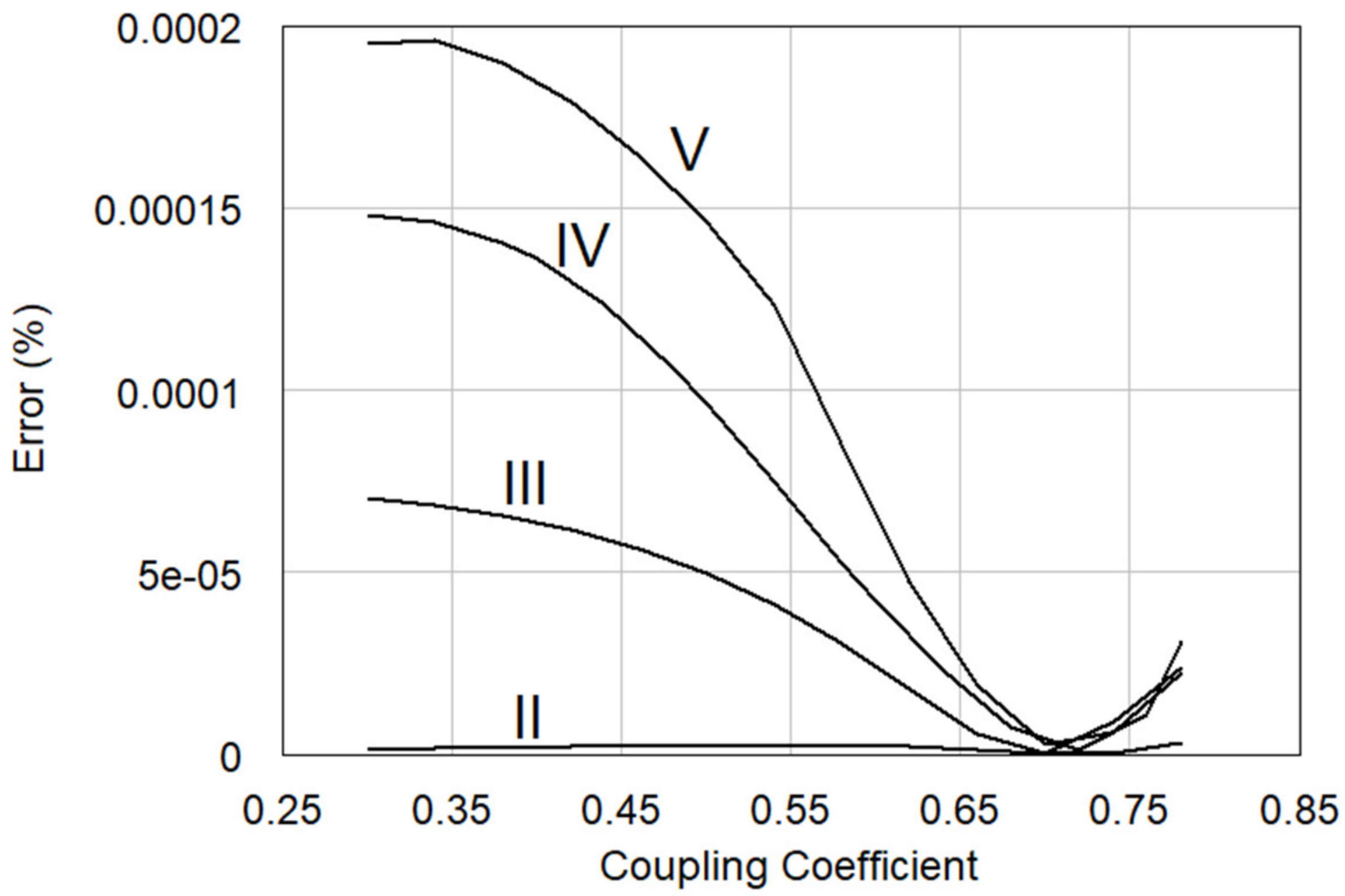
2. Theoretical Analysis

The schematic diagram of a proposed broadband branch-line coupler has been presented in Figure 1. The structure is composed of two sub-circuits: the classic narrowband branch-line ring with transmission-lines having impedances ZA, and ZB (sub-circuit I), and four N-section impedance transformers (named sub-circuit II). The classic branch-line ring can achieve the required power split between ports of the coupler by proper selection of transmission-lines’ impedances ZA, and ZB. Thus, the Equations (1) and (2) can be implemented, where k is the required coupling coefficient of the coupler. In such couplers, the decrease of coupling coefficient results in the increase of the characteristic impedances ZA, and ZB, as shown in Figure 2, and can be a significant limitation in fabrication.
In order to enhance operational bandwidth, the N-order impedance transformer can be utilized which is realized by using quarter-wave transmission lines with impedances Z1ZN, where N is a number of connected in cascade quarter-wave transmission-lines sections.
Z A = Z 0 1 k 2
Z B = Z 0 1 k 2 1
As can be noticed, such a coupler features double symmetry, thus the odd–even mode analysis can be utilized to synthesize the entire coupler’s response. Such an idea has been implemented and the equivalent sub-circuits have been shown in Figure 3. The ABCD matrix of cascade connection of N transmission-lines, forming an N-section impedance transformer can be calculated as follows:
A B C D T L S =   A B C D T L 1   ·   A B C D T L 2   ·   ·   A B C D T L N
where the matrix for each transmission line is given by:
A B C D T L N = cos θ i Z N sin θ i Y N sin θ cos θ
As can be seen in Figure 3, in the odd–even analysis an N-section transformer is the same for each case. Furthermore, it can be noticed, that the output impedance of such a transformer is directly related to parallel-connected transmission lines which form the branch-line ring. Thus, the impedances ZEE, ZEO, ZOE, ZOO for even–even, even–odd, odd–even, and odd–odd modes can be derived as follows:
Z 1 E E = i Z 0 2 1 cot θ 2
Z 1 E O = i Z 0 1 tan θ 2 2 cot θ 2
Z 1 O E = i Z 0 1 2 tan θ 2 cot θ 2
Z 1 O O = i Z 0 2 1 tan θ 2
To determine return loss function of a branch-line coupler, the input impedance and the reflection coefficients have been found. The input impedance can be easily derived by utilizing a well known equation calculated for each odd–even mode:
Z I N N M = A · Z O U T N M + B C · Z O U T N M + D
where N and M define the considered excitation (i.e., even–even, even–odd, odd–even or odd–odd mode), and ABCD parameters are calculated from Equation (3).
Having input impedance, the reflection coefficient can be calculated:
Γ N M = Z I N N M Z 0 Z I N N M + Z 0
Then the reflection coefficient of the entire broadband branch-line coupler can be calculated as:
S k k   C = 1 4 Γ E E + Γ E O + Γ O E + Γ O O
where k is the port number (k = 1 to 4). To obtain the flat response of a coupling function and the required return losses of a coupler, the Chebyshev approximation has been utilized. In [23] the authors deliver a general equation for a rat-race coupler:
S k k I = 1 + h 2 1 + 1 x c 2 T n x x c 1 1 x c 2 T n 2 x x c 2 1 x 2 2
which can be adopted to synthesize an ideal response of a broadband branch-line coupler. A desirable reflection ripple is defined by h parameter, Tn and Tn−2 are Chebyshev polynomials of the first kind, x and xc are cos(θ), cos(θc) respectively, and θc determines lower frequency of operational bandwidth given by:
f d = 2 f c π · θ c
Furthermore, the operational bandwidth can be calculated from:
B W % = 2 f c π 2 θ c π   ·   100 %
The difference between synthesized circuit response Skk(C), and ideal Chebyshev response Skk(I) can be calculated by utilizing the chosen cost function E. To verify variance of an error in operational range, θc to πθc, the mean integrated square error has been considered:
E = θ c π θ c S k k C θ S k k I θ 2 d θ
It should be noted that the branch-line coupler is clearly defined by Chebyshev response when E = 0.

3. Broadband Branch-Line Coupler Design

The proposed design method has been implemented numerically. To find the lowest value of cost function E, the Nelder–Mead simplex algorithm [24] has been used. Figure 4 shows the characteristics obtained for cases where values of an N-section transformer’s impedances are not limited. Therefore, such a graph presents an error related to the considered numerical method. The results show that the greater the number of sections, the bigger the error value. It is intuitive that additional sections increase operational bandwidth, which is presented in Figure 5. On the other hand, the widest bandwidth values are obtained for the weakest coupling the largest reflection coefficients, as seen in Figure 6. The impact of coupling coefficient on the reflection response for the coupler with a II-section transformer is presented in Figure 7.
To investigate the possibility of the physical realization of broadband branch-line couplers, the impedances of transformer’s sections have been calculated. The obtained results for II and III-section transformers are presented in Figure 8. It is well-known that high-impedance transmission lines require the realization of narrow microstrip lines, often below the technological limits. Thus, from the practical point of view some technological limitations must be considered. As can be seen in Figure 8a,c the coupler with II-section transformers can be realized with impedance values below 100 Ω which is easily realizable in a standard microstrip technique. For the III-section case, physical implementation can be difficult while impedances can exceed 400 Ω, which is presented in Figure 8b,d. In Figure 9 the impact of not-limited and limited impedance values on reflection coefficient’s characteristics for 3-dB, 6-dB, and 10-dB III-section couplers are shown. As an impedance limitation a value of 4Z0, has been assumed, where Z0 = 50 Ω. In every calculated case, a broadband character has been retained, however, levels of function zeros have been increased (the obtained characteristics are less similar to the Chebyshev polynomial functions). Furthermore, the operational bandwidth has been also enhanced. In the Appendix, the calculated normalized values of impedances composing broadband branch-line couplers are presented.

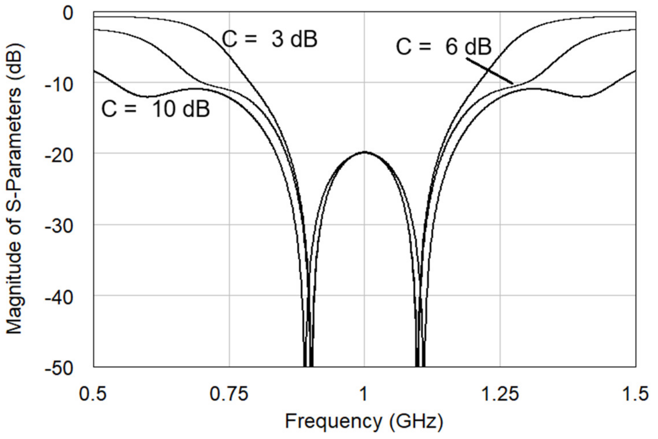
4. Experimental Realization of 6-dB, and 3-dB Broadband Branch-Line Couplers

4.1. 6-dB Broadband Branch-Line Coupler with II-Section Transformer

To verify correctness, and applicability of the proposed design method a 6-dB branch-line directional coupler with a II-section transformer, having 20 dB return losses, has been designed, fabricated, and measured. The ideal electrical parameters have been found by utilizing the derived equations and are listed in Table 1. The ideal response has been presented in Figure 10. For further fabrication the microstrip structure shown in Figure 11 has been selected, for which h = 1.52 mm and εr = 3.38. Figure 12 shows response of the 6-dB coupler obtained from electromagnetic calculations using AWR Microwave Office. The center frequency is equal to 2 GHz. The considered branch-line coupler has been fabricated and measured. The obtained results have been collected and compared to the calculated ones in Figure 12a–c. As can be noticed, the measurements are in good agreement with the simulated responses. The return loss is lower than 19.4 dB, whereas the isolation is greater than 25.2 dB. Furthermore, the phase imbalance is smaller than 1.1° in the operational bandwidth.

4.2. 3-dB Broadband Branch-Line Coupler with III-Section Transformer

To verify the possibility of realization of higher order couplers, a 3-dB branch-line coupler with III section transformer, having return losses equal to 20 dB has been designed using a similar substrate as in the preceding example having h = 1.52 mm and εr = 2.5. In this case the maximum values of transmission-line impedances are crucial. Thus, the impedances taken into account during the calculations have been limited to the values which can be fabricated. The calculated response of such a circuit ia presented in Figure 13. The coupler has been simulated electromagnetically in the AWR Microwave Office, fabricated, and measured. For comparison purpose, the obtained simulations results, and measurements are presented in Figure 14a–c. As can be seen, the measured reflection coefficient is lower than −18.7 dB, whereas the isolation is greater than 18.5 dB. Furthermore, the imbalance of differential phase is not greater than 0.7° in the operational bandwidth. Pictures of the fabricated broadband directional couplers are shown in Figure 15. The overall size of the fabricated components are 5.5 × 13 cm, 5 × 20 cm, respectively, for the II and the III-order coupler.

5. Conclusions

A new design method of broadband arbitrary coupled branch-line couplers has been comprehensively investigated in this paper. In has been proven that the operational bandwidth of a classic branch-line ring can be enhanced by utilizing an N-section transformer connected to each port. Furthermore, it has been shown that in such a solution an arbitrary coupling can be easily implemented by selecting proper impedance values of lines constituting the branch-line ring. The synthesis process with the use of Chebyshev polynomials, and analysis of electrical parameters of broadband branch-line couplers have presented. Moreover, the applicability of proposed design method has been verified by fabrication of 3-dB and 6-dB branch-line couplers featuring good electrical responses. Appendix A presents the corresponding parameters about electrical parameters of broadband branch-line couplers.

Author Contributions

Conceptualization and Investigation, R.S.; Methodology, S.G. and K.W.; Supervision, S.G.; Writing—original draft, R.S., K.W. and S.G. All authors have read and agreed to the published version of the manuscript.

Funding

This work was supported by the National Science Centre Poland under Contract 2016/21/B/ST7/02200.

Conflicts of Interest

The authors declare no conflict of interest.

Appendix A

In this chapter, the electrical parameters of ideal (not-limited) values of transformers’ impedances have been collected for II–III-sections broadband branch-line couplers and are listed in Table A1. Table A2 presents the corresponding parameters for limited values of transformers’ impedances. The presented numbers are normalized to impedance Z0. For calculation the Nelder—Mead algorithm has been used.
Table A1. Normalized electrical Parameters of broadband branch-line couplers with N-Section transformers (ZN(Max) >> 4Z0).
NRL (dB)C (dB)ZAZBZ1Z2Z3
21530.70630.99761.68781.4122---
60.86531.72661.62941.4413---
100.94873.00001.74121.5734---
2030.70630.99761.74131.5749---
60.86531.72661.56131.4582---
100.94873.00001.55121.4659---
2530.70630.99761.76661.6680---
60.86531.72661.51731.4605---
100.94873.00001.46591.4203---
3030.70630.99761.76121.7062---
60.86531.72661.50711.4754---
100.94873.00001.43651.4113---
31530.70791.0002.29474.74842.0632
60.86531.72661.67942.67491.5454
100.94873.00001.36921.73641.2355
2030.70791.0002.33305.89772.5263
60.86531.72661.74193.26791.8412
100.94873.00001.48632.30631.5245
2530.70791.0002.33506.67752.8653
60.86531.72661.78023.71182.0625
100.94873.00001.60262.93601.8123
3030.70791.0002.36017.37883.1264
60.86531.72661.80624.04742.2273
100.94873.00001.62153.15701.9349
Table A2. Electrical Parameters of broadband branch-line couplers with III-section transformers obtained for limited values of transformer impedances (ZN(Max) = 4Z0).
RL (dB)C (dB)ZAZBZ1Z2Z3
1530.70791.0002.07903.99911.8800
60.86531.72661.67772.66851.5434
100.94873.00001.77562.98851.6710
2030.70791.0001.85204.00002.0600
60.86531.72661.74063.26221.8394
100.94873.00001.77563.26111.8399
2530.70791.0001.49103.19402.0685
60.86531.72661.77563.69162.0566
100.94873.00001.82903.88002.1123
3030.70791.0001.67304.00002.3200
60.86531.72661.77413.90102.1848
100.94873.00001.59343.02811.8887

References

  1. Oliver, B. Directional Electromagnetic Couplers. Proc. IRE 1954, 42, 1686–1692. [Google Scholar] [CrossRef]
  2. Emery, T.; Chin, Y.; Lee, H.; Tripathi, V.K. Analysis and design of ideal non symmetrical coupled microstrip directional couplers. In Proceedings of the IEEE MTT-S International Microwave Symposium Digest, Long Beach, CA, USA, 13–15 June 1989; pp. 329–332. [Google Scholar]
  3. Gruszczynski, S.; Wincza, K. Generalized methods for the design of quasi-ideal symmetric and asymmetric coupled-line sections and directional couplers. IEEE Trans. Microw. Theory Tech. 2011, 59, 1709–1718. [Google Scholar]
  4. Lin, S.; Eron, M.; Turner, S.; Sepulveda, J. Development of wideband low-loss directional coupler with suspended stripline and microstrip line. Electron. Lett. 2011, 47, 1377–1379. [Google Scholar]
  5. Gruszczynski, S.; Wincza, K.; Sachse, K. Design of compensated coupled-stripline 3-dB directional couplers, phase shifters and magic-Ts—Part I: Single-section coupled-line circuits. IEEE Trans. Microw. Theory Tech. 2006, 54, 3986–3994. [Google Scholar]
  6. Shelton, J.P.; Wolfe, J.; Wagoner, R.C. Tandem couplers and phase shifters for multi-octave bandwidths. Microwaves 1965, 4, 14–19. [Google Scholar]
  7. Tang, C.-W.; Tseng, C.-T.; Hsu, K.-C. Design of the Modified Planar Tandem Couplers with a Wide Passband. IEEE Trans. Microw. Theory Tech. 2012, 61, 48–54. [Google Scholar] [CrossRef]
  8. Lange, J. Interdigitated Stripline Quadrature Hybrid (Correspondence). IEEE Trans. Microw. Theory Tech. 1969, 17, 1150–1151. [Google Scholar] [CrossRef] [Green Version]
  9. Janisz, K.; Smolarz, R.; Rydosz, A.; Wincza, K.; Gruszczynski, S. Compensated 3-dB lange directional coupler in suspended microstrip technique. In Proceedings of the 7th IEEE International Symposium on Microwave, Antenna, Propagation, and EMC Technologies (MAPE), Xi’an, China, 24–27 October 2017; pp. 1–4. [Google Scholar]
  10. Eccleston, K.; Ong, S. Compact planar microstripline branch-line and rat-race couplers. IEEE Trans. Microw. Theory Tech. 2003, 51, 2119–2125. [Google Scholar] [CrossRef] [Green Version]
  11. Sun, K.-O.; Ho, S.-J.; Yen, C.-C.; van der Weide, D. A compactbranch-line coupler using discontinuous microstrip lines. IEEE Microw. Wirel. Compon. Lett. 2005, 15, 519–520. [Google Scholar]
  12. Hirota, T.; Minakawa, A.; Muraguchi, M. Reduced-size branch-line and rat-race hybrids for uniplanar MMIC’s. IEEE Trans. Microw. Theory Tech. 1990, 38, 270–275. [Google Scholar] [CrossRef]
  13. Smolarz, R.; Wincza, K.; Gruszczynski, S. Broadband low-loss impedance transforming rat-race coupler in suspended microstrip technique. In Proceedings of the 2018 22nd International Microwave and Radar Conference (MIKON), Poznan, Poland, 14–17 May 2018; pp. 291–293. [Google Scholar]
  14. Tang, C.-W.; Chen, M.-G.; Lin, Y.-S.; Wu, J.-W. Broadband microstrip branch-line coupler with defected ground structure. Electron. Lett. 2006, 42, 1458–1460. [Google Scholar] [CrossRef]
  15. Dilshad, U.; Chen, C.; Chen, X.; Miao, J. Broadband Quadrature Hybrid for Image Rejection in Millimeter-wave Receivers. In Proceedings of the 2019 16th International Bhurban Conference on Applied Sciences and Technology (IBCAST), Islamabad, Pakistan, 8–12 January 2019; pp. 975–978. [Google Scholar]
  16. Lee, S.; Lee, Y. Wideband Branch-Line Couplers with Single-Section Quarter-Wave Transformers for Arbitrary Coupling Levels. IEEE Microw. Wirel. Compon. Lett. 2011, 22, 19–21. [Google Scholar] [CrossRef]
  17. Alshamaileh, K.A.; Devabhaktuni, V.K.; Dib, N.I. Impedance-Varying Broadband 90° Branch-Line Coupler with Arbitrary Coupling Levels and Higher Order Harmonic Suppression. IEEE Trans. Compon. Packag. Manuf. Technol. 2015, 5, 1507–1515. [Google Scholar]
  18. Chiu, L.; Xue, Q. Investigation of a Wideband 90° Hybrid Coupler with an Arbitrary Coupling Level. IEEE Trans. Microw. Theory Tech. 2010, 58, 1022–1029. [Google Scholar]
  19. Lee, J.; Lee, J.; Park, M.-J. Branch-Line Couplers with Arbitrary Coupling Value through the Electrical Length Variation with Fixed Line Impedances. IEEE Microw. Wirel. Compon. Lett. 2017, 27, 968–970. [Google Scholar] [CrossRef]
  20. Arriola, W.A.; Lee, J.Y.; Kim, I.S. Wideband 3 dB Branch Line Coupler Based on λ/4 Open Circuited Coupled Lines. IEEE Microw. Wirel. Compon. Lett. 2011, 21, 486–488. [Google Scholar] [CrossRef]
  21. Kawai, T.; Taniguchi, H.; Ohta, I.; Enokihara, A. Broadband branch-line coupler with arbitrary power split ratio utilizing microstrip series stubs. In Proceedings of the 40th European Microwave Conference, Paris, France, 28–30 September 2010; pp. 1170–1173. [Google Scholar]
  22. Ahn, H.-R.; Tentzeris, M.M. Arbitrary Power-Division Branch-Line Hybrids for High-Performance, Wideband, and Selective Harmonic Suppressions from 2f0. IEEE Trans. Microw. Theory Tech. 2019, 67, 978–987. [Google Scholar] [CrossRef]
  23. Chang, C.-Y.; Yang, C.-C. A novel broad-band Chebyshev-re-sponse rat-race ring coupler. IEEE Trans. Microw. Theory Tech. 1999, 47, 455–462. [Google Scholar]
  24. Lagarias, J.C.; Reeds, J.A.; Wright, M.H.; Wright, P.E. Convergence Properties of the Nelder--Mead Simplex Method in Low Dimensions. SIAM J. Optim. 1998, 9, 112–147. [Google Scholar] [CrossRef] [Green Version]
Figure 1. Schematic diagram of a branch-line coupler with enhanced bandwidth, and arbitrary power division.
Electronics 09 01828 g001
Figure 2. ZA and ZB impedance values vs. coupling coefficient for a narrowband branch-line directional coupler.
Electronics 09 01828 g002
Figure 3. Equivalent sub-circuits of a N-section broadband branch-line coupler under odd–even mode analysis.
Electronics 09 01828 g003
Figure 4. Error values vs. coupling coefficient obtained from error function E (12). Calculations have been made for a branch line coupler with II, III, IV, and V-section transformers.
Electronics 09 01828 g004
Figure 5. Operational bandwidth vs. coupling coefficient for a branch line coupler with II, III, IV, and V-section transformers.
Electronics 09 01828 g005
Figure 6. Reflection coefficient vs. operational bandwidth for a branch line coupler with II, III, IV, and V-section transformers.
Electronics 09 01828 g006
Figure 7. Calculated response of a broadband branch-line coupler with a II-section transformer for h = 0.1, and for different coupling levels C = 3, 6 and 10 dB.
Electronics 09 01828 g007
Figure 8. Impedance values obtained for a 6-dB directional coupler with a II-section transformer (a,c), and a 3-dB directional coupler with a III-section transformer (b,d) vs. coupling coefficient and reflection coefficient, respectively.
Electronics 09 01828 g008aElectronics 09 01828 g008b
Figure 9. Reflection coefficients calculated for broadband branch-line couplers with III-section transformers. Characteristics calculated for 3-dB (a), 6-dB (b), and 10-dB (c) coupling coefficients, and h = 0.1. Dashed lines present ideal responses (for not-limited range of impedances), while solid ones are calculated for ZN(Max) < 4Z0.
Electronics 09 01828 g009
Figure 10. Response of the ideal 6-dB broadband branch-line coupler with the II-section transformer. Results of circuit analysis with circuit values listed in Table 1.
Electronics 09 01828 g010
Figure 11. Cross-sectional view of the dielectric structure considered for the design of broadband branch-line couplers.
Electronics 09 01828 g011
Figure 12. Simulations (dashed lines), and measurements (solid lines) of the 6-dB broadband branch-line coupler with the II-section transformer. (a) Amplitude characteristics; (b) Reflection coefficients; (c) Differential phases.
Electronics 09 01828 g012
Figure 13. Response of the ideal 3-dB broadband branch-line coupler with the III-section transformer. Results of circuit analysis with circuit values listed in Table 1 (impedance limited to 4Z0).
Electronics 09 01828 g013
Figure 14. Simulations (dashed lines), and measurements (solid lines) of the 6-dB broadband branch-line coupler with the II-section transformer. (a) Amplitude characteristics; (b) Reflection coefficients; (c) Differential phases.
Electronics 09 01828 g014
Figure 15. Picture of the measurement setup (a), fabricated 6-dB branch-line coupler with the II-section transformer (b), and the 3-dB branch-line coupler with the III-section transformer (c).
Electronics 09 01828 g015
Table 1. Electrical Parameters of ideal broadband branch-line couplers with II and III-section transformers.
II-SectionIII-Section
Coupling (dB)6.03.0
Return Loss (dB)20.020.0
ZA (Ω)43.2735.35
ZB (Ω)86.3350.00
Z1 (Ω)78.4192.6
Z2 (Ω)73.24200.0
Z3 (Ω)---103.0
Publisher’s Note: MDPI stays neutral with regard to jurisdictional claims in published maps and institutional affiliations.

