Abstract
Electromagnetic fully variable valve train (EMVT) technology promises to improve the fuel economy and optimize the engine performance. A novel EMVT equipped with a magnetorheological buffer (EMVT with MR buffer) is proposed to suppress the valve seating impact in this paper. The magnetorheological buffer can adjust the damping characteristics of the whole system in the seating process. Valve precise motion control and better seating performance can be achieved through the coordinated control of electromagnetic linear actuator (EMLA) and MR buffer. For better analysis of system performance, establishing an accurate system dynamic model is the basis of the coordinated control system. A high-order nonlinear precise model integrating dynamics, electromagnetism, and fluid mechanic was established. Then, the Jacobi linearization model is carried out at the equilibrium seating point to build a control-oriented linearized model. The correctness and accuracy of the linearized model is verified. Experiments and simulations show that the valve precise motion can be well controlled to achieve fully variable actuation. And the valve soft landing can be completed under collaborative control.
1. Introduction
The camless valve trains are considered to improve the performance of internal combustion engines in recent research [1,2]. The camless variable valve train (VVT) systems eliminate the camshafts and the valves can be driven by electromagnetic actuations [3,4], electrohydraulic actuations [5,6], or electro-pneumatic actuations [7]. The electromagnetic VVT (EMVT) is identified as the most flexible VVT employing sensitive electromagnetic linear actuator (EMLA) to draw the valve to open and close. EMVT can control various factors of timing of gas distribution in high efficiency. The valve timing, the opening duration, the lift can be freely adjusted in various working conditions through electronic control to achieve the optimal timing of gas distribution [8].
One of the main challenges in the research of EMVT is the difficulty to achieve the soft landing of the valve for closing operations. Because of the nonlinear characteristics of electromagnetic force, valves and valve retainers are prone to take the impact with large noise under high velocity [9]. High seating velocity leads to the sharp rebound of valve, and even affects the valve close in time.
For seating impact suppression, researchers use complex control algorithms to control EMVT. Most studies use feedforward control or feedback control to control the seating velocity [10,11]. Peterson K.S [12] used the extreme search algorithm and the eddy current sensor to measure the impact strength in soft landing research. Eyabi P [13] constructed an accurate non-linear model and used the synovial control algorithm to control the seating velocity between 0.35 m/s and 0.05 m/s. The disadvantage of synovial control is that it is prone to generate local shake. Hoffmann W [14] used iterative learning control method to simulate and control EMVT moving, and achieved satisfactory results. After continuous experiments, the valve can track the desired trajectory and the valve seating velocity can be reduced to 0.04 m/s employing iterative learning method. These control methods can achieve better seating performance in the laboratory. However, some control methods require high precision of the model and large amount of calculation, which is not conducive to real-time control, and it is not easy to achieve accurate control of valve motion process [15]. Liu L [8] and Zhao J [16] used advanced modeling methods that allow simple linear controller feedback to reduce the amount of calculation. In reference [16], a tracking controller with feedback linearization at the end of the valve travel has been presented, and it verifies that this algorithm successfully controls the movement of electromagnetic valves over a wide range of loads.
Adding the buffers to VVTs is another effective solution for the soft landing. The electro-hydraulic VVTs, designed by Lou Z. [17,18] have a build-in soft-landing feature including hydraulic valves and snubbers for seating velocity control without complex control strategy. In some hydraulic valves research by Huang Y [19], double pulse signals of release solenoid valve are designed to eliminate the impacts of electrohydraulic exhaust valve seating. However, in the research of EMVT, Qiu Y [20] adds a cam-based nonlinear mechanical transformer between the solenoid linear actuator and the valve to solve the landing problem. But the transformer is hard to achieve acceptable power consumption and actuator size. In the research of Zhao J [21], the valve moves in a linear behavior controlled by a rotating motor to ensure a smooth seating performance. A simulation study by Reinholz B [22] introduces a novel cogging-torque-assisted motor-driven (CTAMD) valve actuation system to provide low seating velocity. And experimental researches are displayed and compared to the simulated results as well as other EVA systems to validate the conjectured speed and efficiency of the CTAMD system.
It can be seen from the above that the valve seating impact is mainly suppressed by two technologies: control algorithms for EMVT and adding buffers to EMVT. The control algorithms for EMVT need on-line control or continuous iterative learning, which is more difficult and computational. For adding buffers to EMVT system, there is little research active control for buffers. In fact, the working characteristics of buffers are susceptible to environmental disturbances. Without active control of the buffers, the repeatability of the seating process cannot be guaranteed. In order to simplify the seating control algorithm for EMVT, a novel electromagnetic fully variable valve with a magnetorheological buffer is presented in this paper. An active control method of MR buffer is carried out to avoid operating characteristics being disturbed by the environment. In order to achieve the best performance of the valve, the cooperative control method of EMLA and MR buffer must be studied.
Establishing accurate system dynamics model is the basis of system design and control. Modeling considerations vary according to different research purposes. In order to control the seating velocity, Li H [23] presented the detailed modeling of a novel electro-hydraulic variable valve actuator. The nonlinear mathematical system model is developed component-by-component, considering time delay and time-varying parameters. To analyze the dynamics of different motions, the electromagnetic valve system in research of Di Bernardo M [24] is a highly non-linear piecewise continuous mechanical oscillator. The mechanical system model based on Newton’s law, finite element electromagnetic force model, Coulomb friction model, and valve impact model is established.
For the dynamic modeling of EMVT, most models are constructed separately according to subsystems, and some non-linear factors are considered preliminarily. Some models have simplified processes, neglecting the coupling relationship between subsystems, which is not conducive to the collaborative control of the EMLA and MR buffer. In this paper, it is necessary to establish the coupling relationship between EMLA, MR buffer, and other subsystems. This precise control-oriented model needs to consider dynamics, electromagnetism, and fluid mechanic to analyze system characteristics. Nonlinearity, hysteresis and other characteristics of the system are analyzed in detail.
The EMVT with buffer system mainly consists of EMLA, MR buffer, and spring. The EMLA is a typical electromagnetic direct driving structure and generates electromagnetic force to achieve valve movement requirements. MR buffer has promising applications for providing instantaneous and controllable damping to attenuate vibrations in various dynamic systems [25]. Previously, MR buffers were mainly used in seismic vibration attenuators in heavy machinery [26]. Recently, The small-scale MR buffer is used in the field of rehabilitation robotics [27] and the intelligent bionic leg [28]. The MR buffer can get the damping force by changing the coil current of the buffer to ensure soft-seating for closing operations without complex control methods. With the controllable characteristics of MR buffer damping, the valve movement can be controlled in piecewise variable damping. When the distance from the seating point is large, the MR buffer is in a low-damping state. In fast moving state, the valve can be quickly close to the seating area to achieve rapid response requirement. When the distance from the seating point is less than a set distance, the coil of MR buffer is switched on and current is applied. In seating state, the system damping can be increased and the seating performance can be improved.
The paper is organized as follows. Section 2 describes the system configuration of the EMVT with MR buffer system. In Section 3, The nonlinear mathematical models of the whole system is presented component-by-component. In Section 4, The EMVT with MR buffer model simplification and linearization model at equilibrium point are shown. The correctness and accuracy of the linearized model are verified. In research for precise motion and seating performance, the simulation and experiment results are described and discussed in Section 5. Finally, conclusions are drawn in Section 6.
2. System Configuration
As shown in Figure 1, the EMVT with MR buffer system mainly consists of EMLA, MR buffer, spring, valve, valve head, valve guide. The EMLA, sensor, valve and spring all have the same parameters and are consistent with the structure of reference [8]. MR buffer and connection fixture are added to the whole system. EMLA is composed of an electromagnetic coil, an inner core, and an outer core. The type of actuator is a kind of voice coil motor. The moving parts are the electromagnetic coil and skeleton. The material of the permanent magnet is Nd-Fe-B with a maximum working temperature of about 180 °C. The main structural parameters of EMLA and MR buffer are shown in Table 1 and Table 2. The MR buffer is composed of piston, piston rod, coil, and magnetorheological fluid. The moving parts of the EMLA are connected with the buffer piston by thread. The buffer piston and valve are also threaded. The EMLA provides an electromagnetic force generated by the movement of the electrified coil in the air gap magnetic field to drive the valve open and close. The MR buffer chamber is filled with magnetorheological fluid. MR buffer utilizes rapid variable viscosity plastic effect of MR fluid to generate buffer force. The MR buffer adjusts the buffer force by changing the coil current to achieve a good effect in the process of valve seating. Spring can be used to assist valve closure and realize valve tightness after seating.
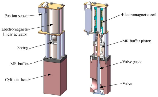
Figure 1.
Structure of the electromagnetic fully variable valve train (EMVT) with MR buffer.

Table 1.
The structural and performance parameters of electromagnetic linear actuator (EMLA).
Table 2.
The structural parameters of MR buffer.
3. Nonlinear Mathematical Dynamic Modeling
In this section, an accurate overall dynamic model of the EMVT with MR buffer system is established, which is coupled with various sub-component mathematical models. The modeling process of EMLA and MR buffer are presented respectively.
3.1. Dynamic Analysis of the EMVT with MR Buffer
The mechanical system of EMVT with buffer can be simplified into a spring-mass-damping system with a single degree of freedom. Its dynamical system model is shown in Figure 2. The forces on the moving parts include Lorentz force, the magnetorheological buffer force, mechanical damping force (including friction and air resistance), elastic force, and pressure of the chamber gas on the top of the valve.
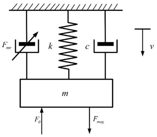
Figure 2.
Diagram of the dynamical model for EMVT with MR buffer.
According to Newton’s second law, the differential equation of engine valve motion is:
where is the effective mass of the whole moving parts, is the valve displacement, represents valve movement velocity, is the electromagnetic force, is the buffer force, is mechanical frictional coefficient, is the spring stiffness, and is the gas pressure.
3.2. The EMLA Model
3.2.1. Circuit Subsystem Model of EMLA
The circuit subsystem model of the EMLA can be equivalent to the circuit in series of resistance, inductance and counter electromotive force, in which the equivalent circuit Figure 3 is shown. When the electromagnetic coil winding moves in the magnetic field of the Halbach array, the cutting magnetic inductance line generates the induced electromotive force at the electromagnetic coil, the magnitude of the induced electromotive force is:
where is the induced electromotive force in the coil, is air-gap flux density, is the total length of effective coil conductors in a magnetic field, represents valve movement velocity, is determined by the structure size and material properties of the EMLA.
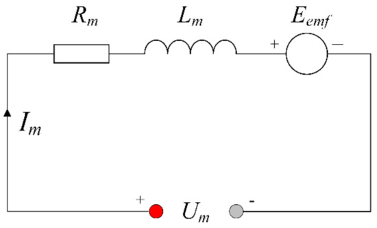
Figure 3.
Equivalent circuit diagram of EMLA.
According to the Figure 3, the steady-state voltage balance equation of the EMLA is:
where , , and are the stable voltage, resistance, inductance of the EMLA.
3.2.2. Magnetic Circuit Subsystem Model
The finite element analysis method can be used to obtain more accurate magnetic field distribution and electromagnetic force. According to the static characteristic curve of the EMLA in Figure 4, it can be seen that the electromagnetic force of the EMLA is affected by the motor current and displacement. The electromagnetic force of the EMLA varies with different positions and loading currents. Least square fitting is used to perform polynomial fitting for the electromagnetic force, displacement and loading current. The functional relations are obtained as follows:
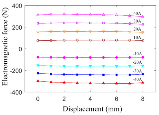
Figure 4.
Electromagnetic force characteristic curve.
Specific electromagnetic force parameters are shown in Table 3.
Table 3.
Coefficient identification results of the electromagnetic force.
3.3. The MR Buffer Model
3.3.1. Circuit Subsystem Model of the MR Buffer
The MR buffer coil can be equivalent to the series connection of the inductance and the resistance, and the circuit is shown in Figure 5.
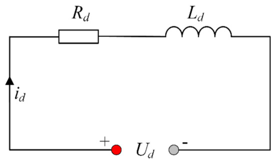
Figure 5.
Equivalent circuit diagram of MR buffer.
According to the Figure 5, the steady-state voltage balance equation of the MR buffer is:
where , , , are the coil voltage, current, resistance, inductance of the MR buffer.
3.3.2. Bingham Model of MR Buffer
According to the theory of magnetorheological mechanics, an idealized mechanical model is assumed for the magnetorheological damping force, which is composed of coulomb friction force and viscous damping force, generally referred to as Bingham model. Bingham model is a pseudo-statics model based on magnetorheological variation. The advantage of Bingham model is that the target buffer current can be calculated by the target buffer force, which is an advantage in the design of control strategies. The schematic diagram of the Bingham model is shown in the Figure 6.
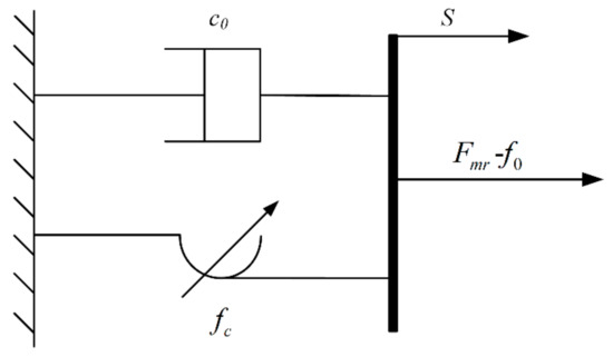
Figure 6.
Modified Bingham model for MR buffer.
The output buffer force is expressed as follows:
where is the viscous damping coefficient, is the coulomb damping force, is the force generated by the existence of compensator. Both and are relevant to the current of the MR buffer.
In order to study the characteristics of the MR buffer accurately, dynamic performance test data are measured under different current situations of 4 mm amplitude and 10 Hz frequency. As there is no compensator in the experiment, so the value is zero. According to the principle of least square method to calculate method, parameter and are identified. The fitting results are in the following Table 4.
Table 4.
Bingham model parameter identification results.
Suppose that and has a quadratic relationship with current. The buffer force can be expressed as follows.
The values of the parameters can be obtained by curve fitting, which are shown in Table 5.
Table 5.
The current coefficient identification results of Bingham model parameters.
3.4. The System Equations for EMVT with MR Buffer System
By integrating the valve motion equation, electromagnetic force model, EMLA circuit model, buffer force model, and MR buffer circuit model, the differential equation of the system can be obtained as follows:
The structural parameters of the EMVT with MR buffer system are shown in Table 6.
Table 6.
The model parameters of the EMVT with MR buffer.
Voltage is applied to the electromagnetic linear actuator, and is applied to the MR buffer as shown in Figure 7. Current is generated in the coil of the EMLA and the electrified coil is subjected to electromagnetic force in the magnetic field. For the application of on the magnetorheological damper, the coil generates current . Current of MR buffer and velocity affect the magnitude of the magnetorheological buffer force. The MR buffer provides variable buffer force for the valve movement during seating process.
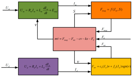
Figure 7.
Coupling of subsystems of EMVT with MR buffer system.
4. Model Linearization and Validation
4.1. Model Linearization
This EMVT with MR buffer system in this paper is an integrated complex system of mechanical, electromagnetism, and liquid coupled multi-object components. The dynamic models of the main parts are correlated and summarized to jointly constitute the model of the whole system. Because of the coil inductances, magnetic flux leakage, eddy current change of EMLA, and the hysteresis characteristics of MR fluid, the model developed in the paper is a nonlinear mathematical model. The nonlinear dynamic model brings difficulties in the design and online implementation of the control algorithm. So the system model needs to be degraded and linearized reasonably to establish a linearized model for modern control theory.
In the differential equation of motion, gas pressure is used to study the impact of gases on valves in various working conditions of engines. At this research stage, we mainly study the valve motion law and seating performance, so can be ignored in this paper. In the Bingham model of damping force, there is which determines the direction of buffer force. For this function, two motion processes (valve opening and closing) can be piecewise processed, to deal with the complexity generated by function.
The EMVT with MR buffer system is a double input and single output system. The state space is expressed as:
where represents dynamic matrices, represents dynamic matrices, represents dynamic matrices, is state vector, is input vector, and is output vector.
Define the states vector as:
Define the input vector as:
Define the output vector as:
Variable formal expression in the EMVT with MR buffer:
After defining the input, output, and state vector, the fraction, and the square in state vector require further linearization. The linearization of the commonly used method for the nonlinear system is Jacobi linearization method. At the equilibrium point of the system, the higher order part of the system can be approximated by Taylor series. The equilibrium point is a special working point. At the equilibrium point of the system, if the input variables are unchanged at this time, the system state variables will keep constant. In other word, the equilibrium point in the system equations reflect that the state variables of the derivative are zero. Jacobi linearization is a local linearization technique, where Taylor series expansion is carried out at the equilibrium point to achieve the first-order linear approximation of the system by ignoring the quadratic and higher order terms.
Using Jacobi linearization, Matrix A and B can be obtained from the following equation:
Among them
is the equilibrium point of the system when .
The ideal moving result is the equilibrium state of the system at the seat point of the valve, where the derivative of displacement, velocity, damper current, and actuator current of the valve are all zero. Since the valve closing point is set to the displacement zero, the ideal state is as follows:
The equilibrium state vector can be obtained as follows:
The equilibrium input vector can be obtained as follows:
The expression of state space after Jacobi linearization is:
The final result is:
4.2. Experiment Setup
The whole test bench is composed of EMVT with MR buffer system, PC, circuit controller-based DSP (digital signal processor) and power supply shown in Figure 8. EMVT with MR buffer system is the control objectives, which is used to research valve opening, closing, and seating characteristics. DSP-based circuit controller is used to drive the EMLA and MR buffer, and it can also collect process displacement, current, and other data. The PC is used for data interaction and communication between DSP controller and the computer. The specific model of displacement sensor is 500 LCIT. LCIT is based on patented linear displacement sensor technology. It has all the advantages of current LVDT induction technology, but is much cheaper. The specific parameters are expressed in Table 7.
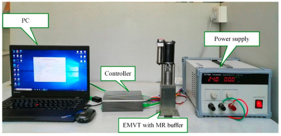
Figure 8.
Test beach.
Table 7.
The main technical parameters of 500 LCIT displacement sensor series.
4.3. Model Validation and Analysis
The Figure 9 is the comparison diagram of experiment and linearized model simulation. Open-loop control (multi-stage PWM adjustment) on EMLA is implemented at different stages to drive the valve in the experiment. The driving voltage of EMLA is high in the early stage and low in the later stage. A certain amount of buffer current is applied to the MR buffer in the later process to verify the effect of MR buffer.
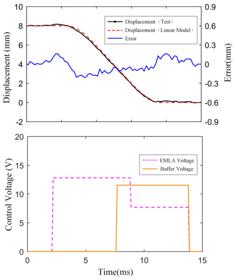
Figure 9.
Linearized model validation.
The same driving voltages signal is applied to the linearized simulation model, and then the displacement curves of experiment and simulation are compared for model validation. The experimental results are consistent with the displacement curve of the linearized model. The maximum average error of experiment and simulation displacement is 3.1%. It can be seen that the electromagnetic force and buffer force can be well simulated in the linearized model, which is well reflected in the displacement.
5. Results and Discussion
5.1. Simulation Results
Figure 10 shows the closed-loop control with multiple attempts simulation results under the developed linearized model. The valve closing process of the valve is often divided into two or more stages. At the beginning of the valve closing process, the EMLA pushes the valve moving in high velocity in order to achieve greater transition time (the time in which the valve moves from 5% of the travel to 95% of the travel). In the simulation, when the lift is 8 mm, transition time is about 4.3 ms. When the displacement is 90% of the total travel, it is defined to enter the seating region A in this paper. Starting buffer work 5% earlier at the end of transition time is beneficial in compensating for the buffer force build-up time. In seating area A, the current applied to the MR buffer coil can increase the damping coefficient of the whole system to reduce the seating velocity. The magnitude of the current can be calculated by the kinetic energy at the beginning and end of the seating stage. At the same time, the EMLA current is adjusted slightly to make the seat successful. After the seating process completed, the buffer current is removed and the EMLA current is applied to the valve for seat holding. The motion control and seating performance are established in simulation under collaborative control of EMLA and MR buffer.
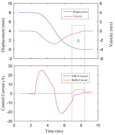
Figure 10.
Simulation result of valve closing process.
5.2. Experiment Results
In the control of valve motion transition process, the inverse system control strategy employed in paper [8] is used. The average transition time is within 4 ms. In EMVT with MR buffer system, the regulation of valve timing is realized by changing the instruction for valve opening and closing time. Changing the valve opening and closing time can not only change the valve timing, but also change the valve opening duration to achieve engine load control. If the valve opening instructions are not sent to EMVT with MR buffer system in a working cycle of the engine to keep the valve closed all the time, the function of valve stagnation or cylinder shutdown can be realized.
In valve moving process of EMVT with MR buffer, valve lifts are arbitray and fully varible between the fully closed position and the fully open position. The flexible adjustment of valve lift can be realized by changing the reference valve lifts of the eletronic control unit. The experimental curves of varible valve lift is shown in Figure 11. The selected reference valve lifts are 4 mm, 6 mm, and 8 mm. Accordingly, the experimental lifts are 8.05 mm, 6.03 mm, and 4.02 mm. Maximum error is 0.05 mm. The transition time is set as 4 ms. The various lifts can be fully adjusted between 0 mm and 8 mm, not limited to the adjustment scheme shown in the figure. The valve opening duration are various by changing the valve closing time. Valve opening durations are chosen to be 5 ms (when lift is 4 mm), 10 ms (when lift is 6 mm), and 15 ms (when lift is 8 mm). The valve timing is flexible in Figure 11 by changing the valve opening and closing time.
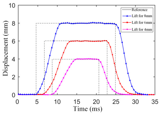
Figure 11.
Experimental results of flexible valve motion control using MR buffer.
The Figure 12 shows the diagram of the control structure for the actuator and MR Buffer. Under coordinated control of EMLA and MR buffer, the valve performs rapid movement and soft landing.Through the feedback of state quantity, EMLA employs the active control method to push the valve toward target displacement. When the valve moves into the buffer area, the certain current is applied to the buffer. We calculate a series of feedforward trajectories from the kinetic energy through the state of motion. The buffer current can be calculated to follow the feedforward trajectories until a low seating velocity is achieved. Figure 13, Figure 14 and Figure 15 show the seating performance when lifts are 8 mm, 6 mm, and 4 mm. They show the displacement and velocity curves of the buffer under different conditions of opening and closing in the valve seating.
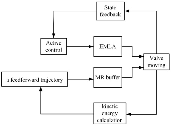
Figure 12.
The diagram of the control structure for seating process.
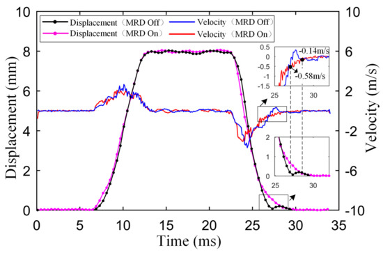
Figure 13.
Experimental result of seating performance when lift is 8 mm.
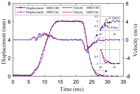
Figure 14.
Experimental result of seating performance when lift is 6 mm.
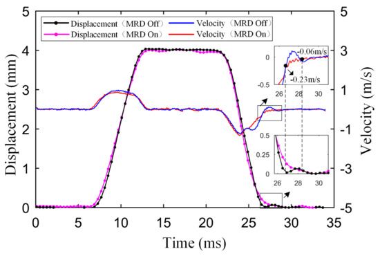
Figure 15.
Experimental result of seating performance when lift is 4 mm.
When the lift is 8 mm, the seating velocity can be reduced from 0.58 m/s to 0.14 m/s without complex control strategy in the Figure 13, and the valve seating rebounding height can be reduced from 0.2 mm to 0.05 mm. When the lift is 6 mm, the seating velocity can be reduced from 0.43 m/s to 0.11 m/s under active control of MR buffer in the Figure 14. When the lift is 4 mm, the seating velocity can be reduced from 0.23 m/s to 0.06 m/s in the Figure 15. From the above, MR buffer can adjust current flexibly according to valve lifts and moving conditions to get better seating characteristics under active control. The current of MR buffer for stroke of 8 mm, 6 mm, 4 mm are shown in Figure 16.
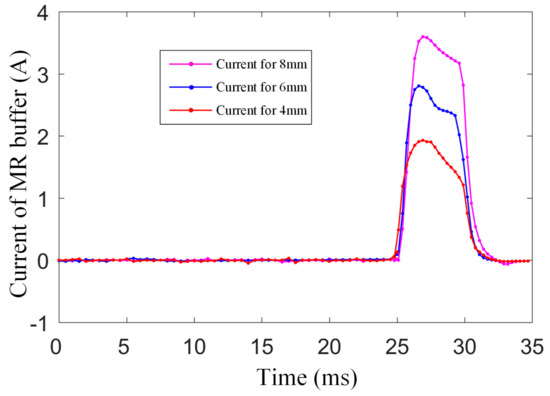
Figure 16.
The current of MR buffer for stroke of 8 mm, 6 mm, 4 mm.
6. Conclusion
This paper describes the detailed modeling process for EMVT with MR buffer. The dynamic, nonlinear and high-order characteristics of the system are fully studied. The model is fitted exactly by least square method and the linearized model is established at the equilibrium point. In validation of the model, the maximum average relative error between validation experiment and simulation model is 3.1%. After linearization, this model can be applied to control research oriented to modern control theory. Inverse system control is used in transition process control, and the transition time can be controlled within 4 ms. The valve motion experimental results show that EMVT with MR buffer can provide fully flexible valve timing and duration. The valve lifts are fully variable under inverse system control. Maximum lift error is 0.05 mm. Adding MR buffer to EMVT has a significant effect on soft landing. The switch control strategy is applied to the MR buffer, and a certain current is applied to the buffer during the seating stage. When the valve lift is 8 mm, the seating velocity can be reduced from 0.58 m/s to 0.14 m/s, and the valve seating rebounding height can be reduced from 0.2 mm to 0.05 mm. When the lift is 6 mm, the seating velocity can be reduced from 0.43 m/s to 0.11 m/s. When the lift is 4 mm, the seating velocity can be reduced from 0.23 m/s to 0.06 m/s. The added mass of the MR buffer does not reduce the size of the transition time. The transition time is between 5% and 95% of the journey time. The transition time can be controlled by active algorithm under different situations. However, adding MR buffer does increase the seating time, which is within 1 ms compared with reference [8]. MR buffer can adjust the current flexibly according to valve lifts and moving conditions to get better seating characteristics under active control. To sum up, experiments and simulations show that the valve precise motion process can be well controlled to achieve fully variable actuation. The valve soft landing can be completed under collaborative control.
Author Contributions
Supervision, L.L. and Z.X.; research, data analysis, original draft—editing, X.Z.; designing the mechanism system, H.G.; technical support, W.H. and L.N.
Funding
This work was supported by the National Natural Science Foundation of China (Grant No. 51975297, 51875290) and Shanghai Aerospace Science and Technology Innovation Fund (SAST2018-107).
Conflicts of Interest
The authors declare no conflict of interest.
References
- Ha, K.P.; Han, D.; Kim, W.T. Development of Continuously Variable Valve Lift Engine. SAE Tech. Pap. 2010. [Google Scholar] [CrossRef]
- Schechter, M.M.; Levin, M.B. Camless Engine. SAE Int. 1996. [Google Scholar] [CrossRef]
- Kim, J.; Chang, J. A new electromagnetic linear actuator for quick latching. IEEE Trans. Magn. 2007, 43, 1849–1852. [Google Scholar] [CrossRef]
- Shiao, Y.; Dat, L.V. A new electromagnetic valve train with PM/EM actuator in SI engines. Trans. Can. Soc. Mech. Eng. 2013, 37, 787–796. [Google Scholar] [CrossRef]
- Gray, J.; Krstic, N.; Chaturvedi, J. Parameter Identification for Electrohydraulic Valvetrain Systems. J. Dyn. Syst. Meas. Control 2011, 133, 064502. [Google Scholar] [CrossRef]
- Sun, Z.; Kuo, T.W. Transient Control of Electro-Hydraulic Fully Flexible Engine Valve Actuation System. IEEE Trans. Control Syst. Technol. 2010, 18, 613–621. [Google Scholar] [CrossRef]
- Ma, J.; Zhu, G.; Hartsig, A. Model-based predictive control of an electro-pneumatic exhaust valve for internal combustion engines. In Proceedings of the American Control Conference, Seattle, WA, USA, 11–13 June 2008. [Google Scholar]
- Liu, L.; Chang, S. Motion control of an electromagnetic valve actuator based on the inverse system method. Proc. Inst. Mech. Eng. Part D J. Autom. Eng. 2011, 226. [Google Scholar] [CrossRef]
- Liu, L.; Chang, S. Improvement of valve seating performance of engine’s electromagnetic valvetrain. Mechatronics 2011, 21, 1234–1238. [Google Scholar] [CrossRef]
- Haskara, I.; Kokotovic, V.V.; Mianze, L.A. Control of an electro-mechanical valve actuator for a camless engine. Int. J. Robust Nonlin. 2004, 14, 561–579. [Google Scholar] [CrossRef]
- Gunselmann, C.; Melbert, J. Improved motion control and energy consumption for sensorless electromagnetical actuators. In Proceedings of the 2003 IEEE 58th Vehicular Technology Conference, Orlando, FL, USA, 6–9 October 2003; pp. 3289–3293. [Google Scholar] [CrossRef]
- Peterson, K.S.; Stefanopoulou, A.G. Extremum seeking control for soft landing of an electromechanical valve actuator. Automatica 2004, 40, 1063–1069. [Google Scholar] [CrossRef]
- Eyabi, P.; Washington, G. Modeling and sensorless control of an electromagnetic valve actuator. Mechatronics 2006, 16, 159–175. [Google Scholar] [CrossRef]
- Hoffmann, W.; Peterson, K.; Stefanopoulou, A.G. Iterative Learning Control for Soft Landing of Electromechanical Valve Actuator in Camless Engines. IEEE Trans. Control Syst. Technol. 2003, 11, 174–184. [Google Scholar] [CrossRef]
- Chladny, R.R.; Koch, C.R. Flatness-based tracking of an electromechanical variable valve timing actuator with disturbance observer feedforward compensation. IEEE Trans. Control Syst. Technol. 2008, 16, 652–663. [Google Scholar] [CrossRef]
- Zhao, J.; Seethaler, R.J. Compensating combustion forces for automotive electromagnetic valves. Mechatron 2010, 20, 433–441. [Google Scholar] [CrossRef]
- Lou, Z.; Deng, Q.; Wen, S.; Zhang, Y. Progress in Camless Variable Valve Actuation with Two-Spring Pendulum and Electrohydraulic Latching. SAE Int. J. Eng. 2013, 1, 319–326. [Google Scholar] [CrossRef]
- Li, H.; Huang, Y.; Zhu, G.M. Linear parameter-varying model of an electro-hydraulic variable valve actuator for internal combustion engines. J. Dyn. Syst. Meas. Control 2017, 140, 1. [Google Scholar] [CrossRef]
- Huang, Y.; Guo, F.; Zhao, C. Study on electrohydraulic exhaust valve of single piston hydraulic free-Piston engine. J. Comput. Theor. Nanosci. 2012, 6, 436–440. [Google Scholar] [CrossRef]
- Qiu, Y.; Perreault, D.J.; Keim, T.A. Optimal cam design and system control for an electromechanical engine valve drive. In Proceedings of the IEEE International Conference on Industrial Technology, Vina Del Mar, Chile, 14–17 March 2010. [Google Scholar]
- Zhao, J.; Seethaler, R.J. A fully flexible valve actuation system for internal combustion engines. IEEE ASME Trans. Mechatron. 2011, 16, 361–370. [Google Scholar] [CrossRef]
- Reinholz, B.; Seethaler, R. Experimental validation of a cogging torque assisted valve actuation system for internal combustion engines. IEEE ASME Trans. Mechatron. 2016, 21, 453–459. [Google Scholar] [CrossRef]
- Li, H.; Zhu, G.M.; Huang, Y. Reduced-order nonlinear model of an electro-hydraulic variable valve actuator for internal combustion engines. In Proceedings of the 2017 13th IEEE International Conference on Control & Automation (ICCA), Ohrid, Macedonia, 3–6 July 2017; Volume 140. [Google Scholar] [CrossRef]
- Di Bernardo, M.; Di Gaeta, A.; Hoyos Velasco, C.I. Energy-based key-on control of a double magnet electromechanical valve actuator. IEEE Trans. Control Syst. Technol. 2012, 20, 1133–1145. [Google Scholar] [CrossRef]
- Gendeshmin, S.R.; Davarnia, D. Using block pulse functions for seismic vibration semi-active control of structures with MR dampers. Results Phys. 2018, 8, 914–919. [Google Scholar] [CrossRef]
- Pang, H.; Liu, F.; Xu, Z. Variable universe fuzzy control for vehicle semi-active suspension system with MR damper combining fuzzy neural network and particle swarm optimization. Neurocomputing 2018, 306, 130–140. [Google Scholar] [CrossRef]
- Park, J.; Yun, D.; Park, D.I. Dynamic simulation of joint module with MR damper for mobile rescue robot. In Proceedings of the International Conference on Ubiquitous Robots & Ambient Intelligence, Xi’an, China, 19–22 August 2016. [Google Scholar]
- Fei, L.; Xie, H.; Yuan, W.; Liu, Y. The application research of MR damper in intelligent bionic leg. In Proceedings of the 2009 Chinese Control. and Decision Conference; Guilin, China: 17–19 June 2009. [CrossRef]
© 2019 by the authors. Licensee MDPI, Basel, Switzerland. This article is an open access article distributed under the terms and conditions of the Creative Commons Attribution (CC BY) license (http://creativecommons.org/licenses/by/4.0/).