Abstract
Conventional time domain passivity control inevitably embodies division. Zero division can occur under a tiny force or velocity, which may be inevitable, and will be the cause of control crash. To avoid the zero division problem and control crash, we propose a switching dissipation controller for guaranteed stability. The parametric design of the proposed approach is discussed. The switching time domain passivity control is then applied to teleoperation and safe operation is achieved. Simulation and experimental results are demonstrated to validate the effectiveness of the proposed control scheme.
1. Introduction
Teleoperation indicates the operation of a machine at a distance. Applications of teleoperation include underwater exploration, mining, tele-therapy, education, tele-manipulation, e.g., micro-scale teleoperation [1] and tele-surgery [2]. In bilateral teleoperation, slave side force is sent to the master side to enhance the operator’s sense of presence [3]. A historical survey of bilateral teleoperation is given in [4]. An effective approach to teleoperation is the time domain passivity control (TDPC) [5]. Since Hannaford and Ryu’s TDPC approach obseves the flow of the energy, it is referred as the energy based time domain passivity control (ETDPC). To bypass the occurrence of sudden and large force change, a TDPC approach with reference energy following (ETDPC-REF), which is a variant of ETDPC, is proposed in [6].
In parallel to ETDPC-REF, a power-based time domain passivity control (PTDPC) is proposed in [7] with application to haptic control and in [8,9] with application to teleoperation. Chawda and O’Malley address the position drift issues in PTDPC by using r-passivity in [10]. Recently, a four-channel architecture is proposed to promote the transparency of PTDPC [11], together with highly-accurate tracking performance in the presence of constant and decreasing time delays. The TDPC approaches enjoy great popularity due to their simplicity and model-free nature.
However, ETDPC, ETDPC-REF, and PTDPC all inevitably embodies division. That is, they need to divide force or velocity in their passivity controllers (PCs). When the denominator force or velocity is zero, the division operation will lead to infinite control output. Even if the denominators are not exactly zero but close to zero, they may be treated as zero by the sensors and digital signal processor (DSP).Infinite control output definitely causes crash of control and control crash can further lead to instability and safety concerns. Thus, zero division should be avoided as much as possible. To the best of the authors’ knowledge, very little literature has addressed the problem of zero division in TDPC. Specifically, the mechanism proposed in [12], which originally intends to remove the noisy behavior caused by low or zero velocity, naturally eliminates the zero division situation induced by low or zero velocity. But this approach only deals with tiny velocity and tiny force is untouched, and zero division can still happen. Another simpler idea is to deactivate the PC and output a zero under low force or velocity [7]. However, deactivating the PC results in loss of the stability at that instance and the activeness can accumulate. Therefore, a simple approach without loss of passivity, which can even be realized by hardware, is desirable as an alternative.
To bypass the problem of zero division, motivated by switched systems [13], a switching idea was first put forward in [14], and meanwhile, preliminary results were also presented. In this paper, the switching-dissipation-based TDPC, together with its parametric design, is formalized, as a simple but practical solution. Moreover, an analog hardware realization of the proposed PCs is presented. Simulation and experimental results are demonstrated to verify the proposed approach.
2. Time Domain Passivity Control and Zero Division
Suppose that f is the force applied on an object, and v is the resulted velocity. Then is the power. If E is the energy stored in the object, and is the power dissipation of the object, then based on the energy conservation principle, one can have
In TDPC, if , the system is passive [7]. Figure 1 shows the whole teleoperation system. According to it, is transmitted with delay from left to right and becomes ; is transmitted with delay from right to left and becomes , governed by
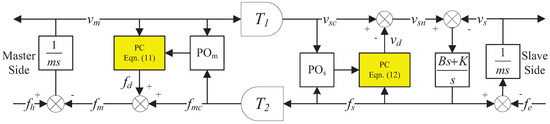
Figure 1.
A teleoperator with conventional TDPC.
The power flow of the bilateral communication (2) is
i.e., the power flow equals the power entering from the left side of the communication minus the power exiting from the right side . After introducing a nonnegative constant b [15], (3) can be rewritten as
If and are both constants, then (4) becomes
where
b relates the different units of force and velocity [15]. If the unit of force is N and the unit of velocity is , the unit of b is . Then the unit of E is , which is an energy unit. E can be viewed as the energy stored in the communication channel.
By comparing (6) with (1), the power dissipation of the bilateral communication under constant delays is
If a system is passive, PTDPC requires [7]. indicates an activeness and the PC action is required.
Since (8) contains signals from both ports of the communication channel with time delay, (8) ≥0 cannot be checked. For real-time checking, (8) ≥0 is separated into two sufficient conditions,
Similar to [9], two passivity observers (POs) and are configured at each port of the communication channel,
If the conventional TDPC in [7,8,9] is used, the passivity controllers (PCs) at each port are
and
Note that and are the outputs of the two PCs. The configuration of this conventional TDPC is shown in Figure 1.
Equations (11) and (12) both have division operation to calculate the outputs of the two PCs, i.e., and . When activeness is observed and the denominator or is zero, the division operation will lead to a large or . A large control output will cause overflow and control crash. Even if the denominators are not exactly zero but close to zero, they may be treated as zero by the sensors and DSP. Therefore, control is dangerous when or is close to zero. Hence the motivation of the switching TDPC clearly lies in control safety.
3. Switching Dissipation for Bilateral Communication
The proposed switching dissipation scheme is illustrated in Figure 2. The operator exerts force to move the master with mass m. And the slave is also with mass m. Meanwhile, the operator feels force where is the output of the master side switching PC. The velocity command for the slave is where is the output of the slave side switching PC. A proportional derivative (PD) controller with proportional gain K and derivative gain B generates force , which overcomes the environmental force . The velocity of the master is and the velocity of the slave is . When , the damper b is activated; when , the damper b is deactivated. When , the damper is activated; when , the damper is deactivated [16,17,18].
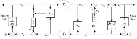
Figure 2.
A teleoperator with switching dissipation.
The passivity controllers at each port are
and
One can see that the zero division is avoided in both controllers. Moreover, the passivity controllers can be simply realized by hardware, thus, eliminating the software computation. An analog realization of the left-hand side PC is devised in Figure 3, which realizes . The right-hand side PC can be realized in the same way.
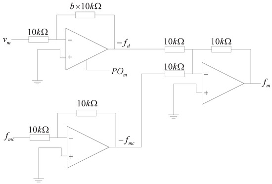
Figure 3.
An analog realization of the left-hand side PC.
If the damper b at the master side is switched on, with the additional dissipation included and noting (13), the power flow of the left-hand port is,
using from Figure 2. It can be seen that the left-hand port dissipation is always nonnegative.
If the damper at the slave side is switched on, with the additional dissipation included and noting (14), the power flow of the right-hand port is,
using from Figure 2. Again the right-hand port dissipation is always nonnegative.
On the contrary, by using the conventional passivity controllers (11) and (12), the counterparts of (15) and (16) are
if and
if . Comparing (17) and (18) with (1), the dissipation at each port is .
Comparing (15) with (17) and comparing (16) with (18), in the switching TDPC, , which means that the proposed approach is more conservative if the passivity controllers are activated. That is to say, the price paid for control safety is the increased conservativeness. One way to improve transparency is to adopt the position-measured force scheme, which reflects the remote environment force instead of the position-computed force, as having been done in [10].
4. Design Suggestion for
4.1. Consideration from the Slave Side
In Figure 2, the slave is modeled as mass m and controlled by a PD controller with derivative gain B and proportional gain K. When the slave side damper is switched on, the transfer function from environmental force to in Figure 2 can be derived as,
Note that the dc gain of is 1 and the time constant of the numerator, , is irrelevant to b. Transfer function (19) can be written into
One can get
Since
increases with b and the upper limit of is
For authentic perception, it is desirable to keep as close as possible to . In other words, one wants the magnitude of as flat as possible and the phase of close to zero within a frequency band as wide as possible.
Since ,
That means when b increases, decreases monotonically.
When , is an overdamped system and the flat part of the magnitude curve will be narrow, in contravention of the “flat-magnitude” expectation. When is small, the resonance peak will be high, again in contravention of the “flat-magnitude” expectation. For a second-order system, a around 0.5 generally leads to a “flat” property, which is also a trade-off between the resonance peak and .
4.2. Consideration from the Master Side
By observing the master side in Figure 2, one can see that b serves as a damper to the operator. High values of b mean strong resistance to the motion of the operator’s hand. Small values of b result in quick moves.
The choice of b should cater for both the master side and slave side. To balance the demands from both sides, one can tune b around the value that makes to achieve the best teleoperation experience.
4.3. Design Example
Suppose the parameters shown in Table 1 are used. If , then and . Figure 4 shows the bode plots of , with b sweeping from 2.5 to 13.

Table 1.
Simulation Parameters.
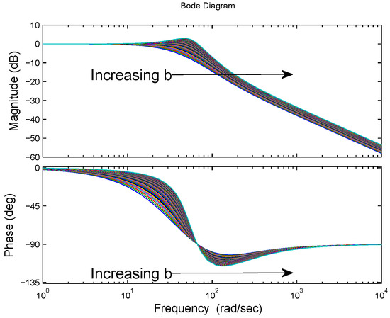
Figure 4.
Bode plots of .
As b increases, the resonance peak moves right and goes high, while the phase response becomes better and better. In consideration of both sides of the communication channel, b is chosen as 6.
5. Simulation Results
The parameters used in the simulations are shown in Table 1. The time delays are s and b is 6. The slave is driven to contact a hard wall with a stiffness K = 30 kN/m located at position m.
5.1. Stability and Safety
When a contact happens, the system is unstable without switching damping. Figure 5a shows that both the master and slave ( and ) oscillate heavily after the slave contacts the hard wall. The environmental contact force is shown in Figure 5b. The energy across the communication channel [the numerical integral of (3)] grows more and more negative as shown in Figure 5c, affirming the instability.
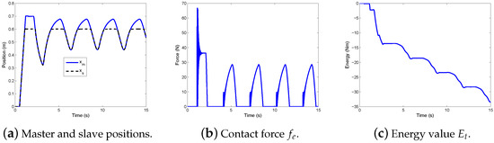
Figure 5.
Position, force and energy responses without dissipation.
Figure 6a,b show the master side PO value and the slave side PO value , respectively. Figure 6c is the sum of the two PO value , i.e., the total dissipation. Because the slave side PO value is mostly negative, the master side PO value is mostly positive, and the sum of the two PO value oscillates between positive and negative, instability mostly comes from the slave side.
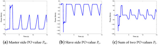
Figure 6.
Power responses without dissipation.
With the switching dissipation in case of a ramp input to the master, a steady contact with the hard wall is achieved, as shown by the master and slave positions in Figure 7a. The contact force is recorded in Figure 7b. Figure 7c,d depict the two dissipation outputs, and , respectively. The forces across the communication channel, and , are illustrated in Figure 7e. The difference between and is trivial, which indicates high force feedback fidelity. The velocities across the communication channel, and , are shown in Figure 7f.
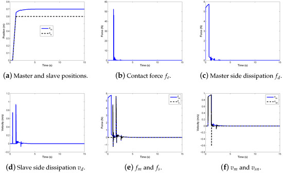
Figure 7.
Switching dissipation for bilateral teleoperation—1.
Figure 8a,b demonstrate the two power-based PO values, and . Although the damping elements are switched on for only a tiny portion of the time, they stabilize the system. The energy is shown in Figure 8c. The energy first keeps increasing and then stays at 3.63 Nm after 2 s, which verifies the stability.
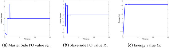
Figure 8.
Switching dissipation for bilateral teleoperation—2.
Take the slave side as an example. In a fixed point DSP like TMS320F2812, if data type _iq23 is adopted, the resolution is . A careful examination of and synchronously reveals that there is 302 points satisfying and along the whole data history. This means that the zero division is avoided 302 times at the slave side.
With the switching dissipation in case of a sinusoidal input to the master, a steady contact with the hard wall is achieved, as shown by the master and slave positions in Figure 9a. The contact force is recorded in Figure 9b. Figure 9c,d depict the two dissipation outputs, and , respectively. The forces across the communication channel, and , are illustrated in Figure 9e. The difference between and is trivial, which indicates high force feedback fidelity. The velocities of the master and slave, and , are shown in Figure 9f.
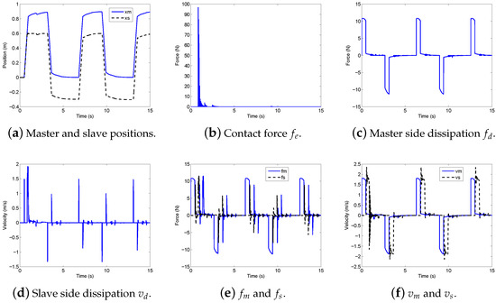
Figure 9.
Switching dissipation for bilateral teleoperation—3.
Figure 10a,b demonstrate the two power-based PO values, and . The damping elements are switched on whenever the passivity observers observe a negative power value. The energy is shown in Figure 10c, again grows more and more positive, indicating stability.
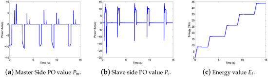
Figure 10.
Switching dissipation for bilateral teleoperation—4.
Remark 1.
From the simulation, one can see that the activeness from the communication channel destabilize the teleoperation system when hard contact happens. The activeness comes from the communication delay. In other words, time delay is the source of instability. With the help of the switching PTDPC, even the outputs of the PCs are minor, the teleoperation system becomes stable under hard contact.
5.2. Compensation of Position Drift
Similar to PTDPC, slave side passivity controller (14) naturally leads to position drift. To make PTDPC practical, Chawda and O’Malley solved the inherent problem of position drift in PTDPC by incorporating r-passivity [10]. r-passivity scheme transmits the “r” signal instead of velocity alone over the communication channel. The “r” signal comprises of both the velocity and position information, as shown in Figure 11. Luckily, r-passivity can again address the position drift issue in the proposed approach.
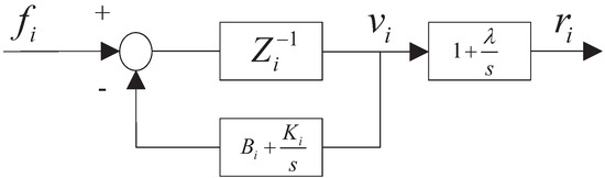
Figure 11.
“r” signal and local feedback passivity controller, [10].
To match the PD parameters in Table 1, the derivative gain is 2.5 and is 148, then is chosen as 14.8010 and is .
The slave is driven to contact the hard wall as in the previous subsection, and then backs out of the contact. This pattern repeats three times. It should be noted that teleoperation without PTDPC was unstable.
The regular switching PTDPC and switching PTDPC with r-passivity are both simulated. Figure 12 shows the master and slave positions of both schemes. Even when the slave leaves the wall and moves in free space, the position drift remains in place with the regular switching PTDPC. It is apparent that the regular switching PTDPC results in accumulated position drift (note the difference between and ), while r-passivity successfully eliminates the position drift. However, r-passivity makes the teleoperator more sluggish, which can be noted by observing the difference between the two master positions in the two sub-figures of Figure 12.
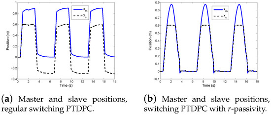
Figure 12.
Position drift solved by r-passivity.
6. Experimental Results
The experiment was performed to test the stability of switching PTDPC approach for teleoperation system. In order to verify the proposed control strategy for teleoperation system, a pair of Novint Falcon, a 3-DOF haptic device, available at the Advanced Control and Mechatronics (ACM) Lab, Department of Mechanical Engineering, Dalhousie University, were utilized as the master and slave, respectively, as shown in Figure 13. The human operator commanded the master, Novint Falcon, to control the position of the slave, Novint Falcon.
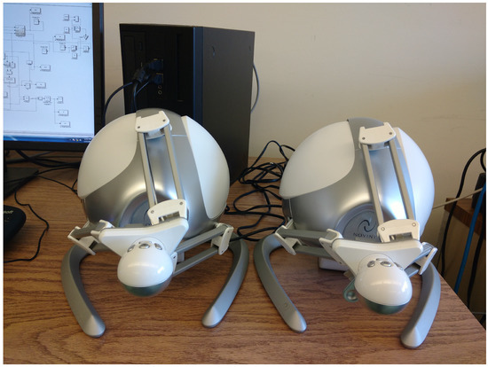
Figure 13.
Experimental setup.
Two desktops with QuaRC real time control systems installation were used as the master and slave platform. QuaRC supports the Novint Falcon haptic devices so all the control algorithms were implemented in MATLAB/Simulink. As the QuaRC library also provides communication blocks for signal transmission between the two desktops, the actual time delay of 1 ms was determined by a simple communication test and for the experiment an additional constant delay of 0.5 s with TCP/IP protocol was introduced as in the simulations. Two experimental tests were performed to validate the effectiveness of the proposed control scheme.
Set 1: The first test was performed with switching PTDPC but without position drift compensation. The parameters for the experiment were chosen exactly the same as in the simulations. However, the environmental force was simulated as where and are the velocity and position of the slave.
With the switching dissipation, a satisfactory trajectory tracking is achieved as shown in Figure 14a. The slave tries to track the position of the master. Even though there is delay in the position tracking of the slave, the tracking results verify the effectiveness of the proposed TDPC approach. As mentioned above, there is no position drift compensation applied in this case so one can easily notice the position drift in slave position. This position drift can be compensated by r-passivity as discussed in the next case of the experimental results. The environmental contact force is recorded in Figure 14b and it can be seen that whenever the slave interacts with the environment there is a spike in the environmental force. Figure 14c,d show the dissipation values and for the master and slave. The forces and across the communication channel in bilateral teleoperation system are shown in Figure 14e. The velocities of the master and slave are shown in Figure 14f. The passivity observer values and for the master and slave are shown in Figure 14g,h, respectively. It can be noted that whenever the passivity observers observe a negative power value, damping is injected in the system by the passivity controllers to maintain the passivity of the teleoperator. The positive energy values in Figure 14i confirm the stable operation under switching PTDPC.
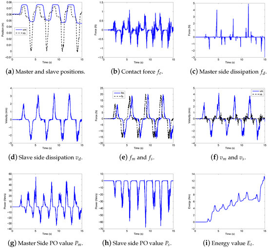
Figure 14.
Set 1: Switching dissipation for bilateral teleoperation.
Set 2: The second test was performed with switching PTDPC and with position drift compensation. The parameters for this set were chosen exactly the same as in the simulations of position drift compensation and the environment was simulated as in the .
The switching dissipation with r-passivity provides a satisfactory trajectory tracking without any position drift as shown in Figure 15a. The comparison of the position results in and substantially makes it clear that r-passivity compensates the position drift in the slave position quite well. The transmission of both the velocity and position information to the slave side results in the desired absence of position drift. The environmental contact force is recorded in Figure 15b. Figure 15c,d show the dissipation values and for the master and slave. The forces and across the communication channel in bilateral teleoperation system are shown in Figure 15e. The velocities of the master and slave are shown in Figure 15f. The passivity observer values and for the master and slave are shown in Figure 15g,h, respectively. It can be noted that whenever the passivity observers observe a negative power value, damping is injected in the system by the passivity controllers. The positive energy values in Figure 15i confirm the stable operation under switching PTDPC.
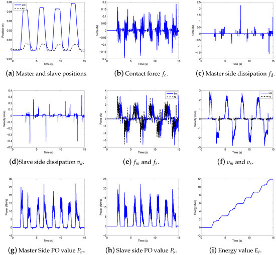
Figure 15.
Set 2: Switching dissipation for bilateral teleoperation.
Remark 2.
Time domain passivity control offers the flexibility of time delay compensation for both constant and time varying delays. In this paper, we are only dealing with the constant delays so the performance of position tracking is not affected much with an increase in time delay. A significant delay of 0.5 s is tested in both simulation and experiment and the proposed control design not only guarantees the stability but provides satisfactory results of position tracking.
7. Conclusions
TDPC is a powerful stabilization tool. However, division operation is standard in conventional TDPC and zero division may cause control crash. In this paper, a switching dissipation scheme is proposed to guarantee the stability by avoiding the zero division and ensuring a safe control. Moreover, the switching TDPC is computationally simple and can be realized by hardware only. The switching dissipation ensures the passivity of the communication channel as well as stable and safe teleoperation. The switching PTDPC is also applicable to r-passivity situation. Simulation and experimental results validate the effectiveness of the switching TDPC approach.
Author Contributions
Conceptualization, L.S. and Y.Y.; simulation program, L.S.; experiments, U.A.; writing—original draft preparation, L.S., U.A. and Y.Y.; writing—review and editing, U.A. and Y.Y.; supervision, Y.-J.P.; funding acquisition, L.S.
Funding
This research was funded by Research Foundation of China University of Petroleum-Beijing at Karamay, grant number RCYJ2018A-02-001.
Conflicts of Interest
The authors declare no conflict of interest.
References
- Ousaid, A.M.; Haliyo, D.S.; Régnier, S.; Hayward, V. A stable and transparent microscale force feedback teleoperation system. IEEE/ASME Trans. Mech. 2015, 20, 2593–2603. [Google Scholar] [CrossRef]
- Osa, T.; Uchida, S.; Sugita, N.; Mitsuishi, M. Hybrid rate—Admittance control with force reflection for safe teleoperated surgery. IEEE/ASME Trans. Mech. 2015, 20, 2379–2390. [Google Scholar] [CrossRef]
- Hua, C.; Yang, Y.; Liu, P.X. Output-feedback adaptive control of networked teleoperation system with time-varying delay and bounded inputs. IEEE/ASME Trans. Mech. 2015, 20, 2009–2020. [Google Scholar] [CrossRef]
- Hokayem, P.F.; Spong, M.W. Bilateral teleoperation: An historical survey. Automatica 2006, 42, 2035–2057. [Google Scholar] [CrossRef]
- Hannaford, B.; Ryu, J.H. Time-domain passivity control of haptic interfaces. IEEE Trans. Robot. Autom. 2002, 18, 1–10. [Google Scholar] [CrossRef]
- Ryu, J.H.; Preusche, C.; Hannaford, B.; Hirzinger, G. Time domain passivity control with reference energy following. IEEE Trans. Control Syst. Technol. 2005, 13, 737–742. [Google Scholar] [CrossRef]
- Ye, Y.; Pan, Y.J.; Gupta, Y.; Ware, J. A power-based time domain passivity control for haptic interfaces. IEEE Trans. Control Syst. Technol. 2011, 4, 874–883. [Google Scholar] [CrossRef]
- Ye, Y.; Pan, Y.J.; Gupta, Y. Time domain passivity control of teleoperation systems with random asymmetric time delays. In Proceedings of the 48th IEEE Conference on Decision and Control Held Jointly with the 28th Chinese Control Conference, Shanghai, China, 15–18 December 2009; pp. 7533–7538. [Google Scholar]
- Ye, Y.; Pan, Y.J.; Hilliard, T. Bilateral teleoperation with time-varying delay: A communication channel passification approach. IEEE/ASME Trans. Mech. 2013, 18, 1431–1434. [Google Scholar] [CrossRef]
- Chawda, V.; O’Malley, M.K. Position synchronization in bilateral teleoperation under time-varying communication delays. IEEE/ASME Trans. Mech. 2015, 20, 245–253. [Google Scholar] [CrossRef]
- Sun, D.; Naghdy, F.; Du, H. Wave-variable-based passivity control of four-channel nonlinear bilateral teleoperation system under time delays. IEEE/ASME Trans. Mech. 2016, 21, 238–253. [Google Scholar] [CrossRef]
- Ryu, J.H.; Hannaford, B.; Kwon, D.S.; Kim, J.H. A simulation/experimental study of the noisy behavior of the time-domain passivity controller. IEEE Trans. Robot. 2005, 21, 733–741. [Google Scholar] [CrossRef]
- Zhang, Y.; Liu, X.; Zhu, H.; Zhong, S. Stability analysis and control synthesis for a class of switched neutral systems. Appl. Math. Comput. 2007, 190, 1258–1266. [Google Scholar] [CrossRef]
- Cheng, J.; Ye, Y.; Wang, D. Avoiding zero division by switching dissipation in time domain passivity control. In Proceedings of the IASTED International Conference on Modelling, Identification, and Control, Phuket, Thailand, 24–26 November 2010; pp. 251–258. [Google Scholar]
- Niemeyer, G.; Slotine, J.J. Stable adaptive teleoperation. IEEE J. Ocean. Eng. 1991, 16, 152–162. [Google Scholar] [CrossRef]
- Ahmad, U.; Pan, Y.J. A time domain passivity approach for asymmetric multilateral teleoperation system. IEEE Access 2018, 6, 519–531. [Google Scholar] [CrossRef]
- Ahmad, U.; Pan, Y.J. Switching time domain passivity control for multilateral teleoperation systems under time varying delays. In Proceedings of the 2016 IEEE 55th Conference on Decision and Control (CDC), Las Vegas, NV, USA, 12–14 December 2016; pp. 1429–1434. [Google Scholar]
- Ahmad, U.; Pan, Y.J.; ul Husnain, A. Switching time domain passivity control for multilateral teleoperation systems. In Proceedings of the 2016 2nd International Conference on Robotics and Artificial Intelligence (ICRAI), Rawalpindi, Pakistan, 1–2 November 2016; pp. 69–74. [Google Scholar]
© 2019 by the authors. Licensee MDPI, Basel, Switzerland. This article is an open access article distributed under the terms and conditions of the Creative Commons Attribution (CC BY) license (http://creativecommons.org/licenses/by/4.0/).