You are currently viewing a new version of our website. To view the old version click .
Electronics
  • Article
  • Open Access

5 February 2019

A Hybrid Dead Reckon System Based on 3-Dimensional Dynamic Time Warping

,
,
,
and
School of Information Science and Engineering, Xiamen University, Xiamen 361001, China
*
Author to whom correspondence should be addressed.
This article belongs to the Section Microwave and Wireless Communications

Abstract

In recent years, using smartphones for indoor positioning has become increasingly popular with consumers. This paper presents an integrated localization technique for inertial and magnetic field sensors to challenge indoor positioning without Wi-Fi signals. For dead-reckoning (DR), attitude angle estimation, step length calculation, and step counting estimation are introduced. Dynamic time warping (DTW) usually calculates the distance between the measured magnetic field and magnetic fingerprint in the database. For DR/Magnetic matching (MM), we creatively propose 3-dimensional dynamic time warping (3DDTW) to calculate the distance. Unlike traditional DTW, 3DDTW extends the original one-dimensional signal to a two-dimensional signal. Finally, the weighted least squares further improves indoor positioning accuracy. In the three different experimental scenarios—teaching building, study room, office building—DR/MM hybrid positioning accuracy is about 3.34 m.

1. Introduction

Because of the popularity of smart devices, mobile location-based services are required to provide real-time, highly reliable, and high-precision indoor positioning. Indoor positioning technology has been widely investigated by researchers [1,2,3]. The global satellite navigation system cannot solve indoor positioning problems. Therefore, people are trying to find other techniques to solve them.
Indoor positioning techniques are usually divided into two categories: infrastructure-based positioning and infrastructure-free positioning. Positioning technique using infrastructure, especially widely used Wi-Fi positioning, is attracting increased attention. To reduce the time and labor costs of constructing a Wi-Fi database, a crowdsourcing-based algorithm is presented to estimate access point localization and propagation parameters [4]. An actual Wi-Fi indoor positioning system is deployed at the COEX complex in Korea [5]. Test results reveal a positioning accuracy of 5 to 8 m. Because of the multipath and the reflection effects, the quality of the Wi-Fi signals depends on the distribution and number of access points and the transmission environment. Another practical problem is that Wi-Fi positioning consumes an inordinate amount of electricity, making it difficult for smartphones to provide long-term positioning. Therefore, this paper presents an indoor positioning technology without Wi-Fi.
The infrastructure-free positioning technique is mainly an inertial positioning system, which obtains a user’s position by integrating acceleration and angular velocity. Compared with Wi-Fi, an inertial positioning system is free from external interference. However, heading drift is unavoidable in an inertial positioning system. Combined with wall information, an auxiliary particle filter is proposed to eliminate the heading drift of the inertial sensor [6]. Furthermore, the literature [7] proposes a firefly particle filter to reduce the inertial accumulation error. MM determines a pedestrian’s location by matching the magnetic field fingerprint in the database. Compared with Wi-Fi, an indoor magnetic field is stable [8]. The indoor ferromagnetic material [9] interferes with the geomagnetic field, causing the magnetic field to vary with position. Binghao Li et al. discussed the feasibility of using a magnetic field for positioning [10]. Based on alternating current magnetic fields, a method for indoor navigation is proposed [11]. However, some beacons must be deployed, which increases positioning costs. For MM, magnetic field mismatch is an unavoidable problem. Based on inertial and magnetic sensors, the MALoc system proposes an actual magnetic field fingerprinting technique [12]. However, the system positioning error depends on the number of particles in the particle filter and the gyroscope reading. To take full advantage of the inertial and magnetic sensors, a DR/MM integrated algorithm is proposed to improve indoor positioning accuracy and robustness. In the integrated positioning system, we use DR results to constrain the magnetic field matching range. In DR/MM, we creatively propose 3DDTW to calculate the distance. Therefore, the main contributions of this article are as follows:
(1)
Integrated indoor positioning system does not require infrastructure to be deployed, greatly reducing the time and money costs.
(2)
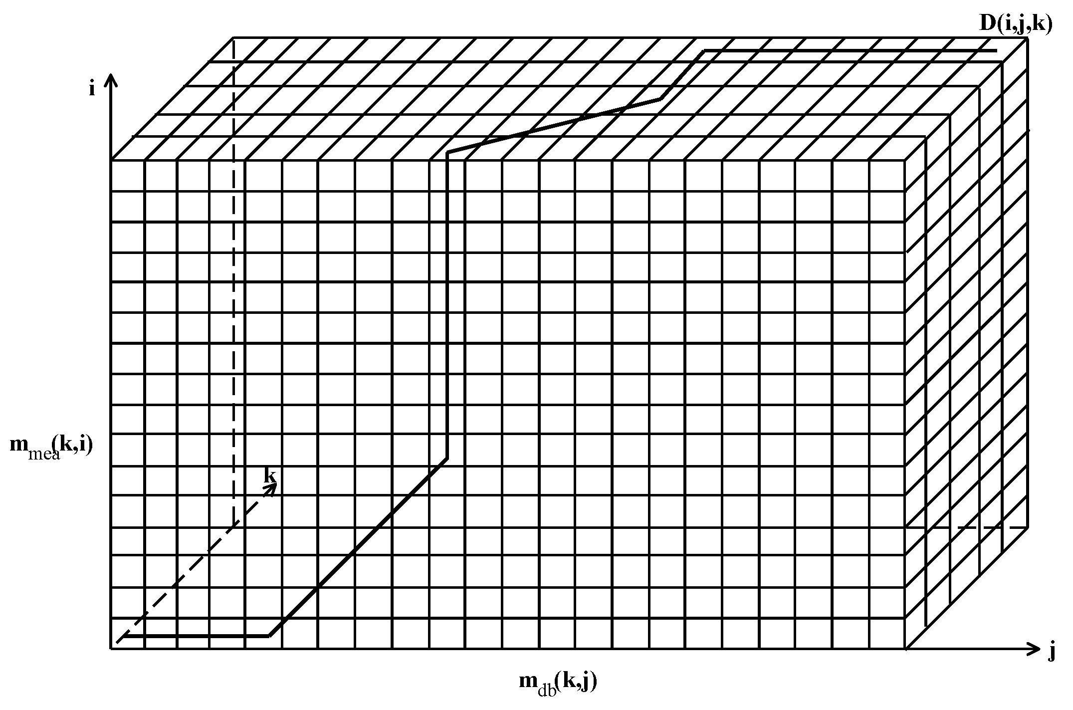
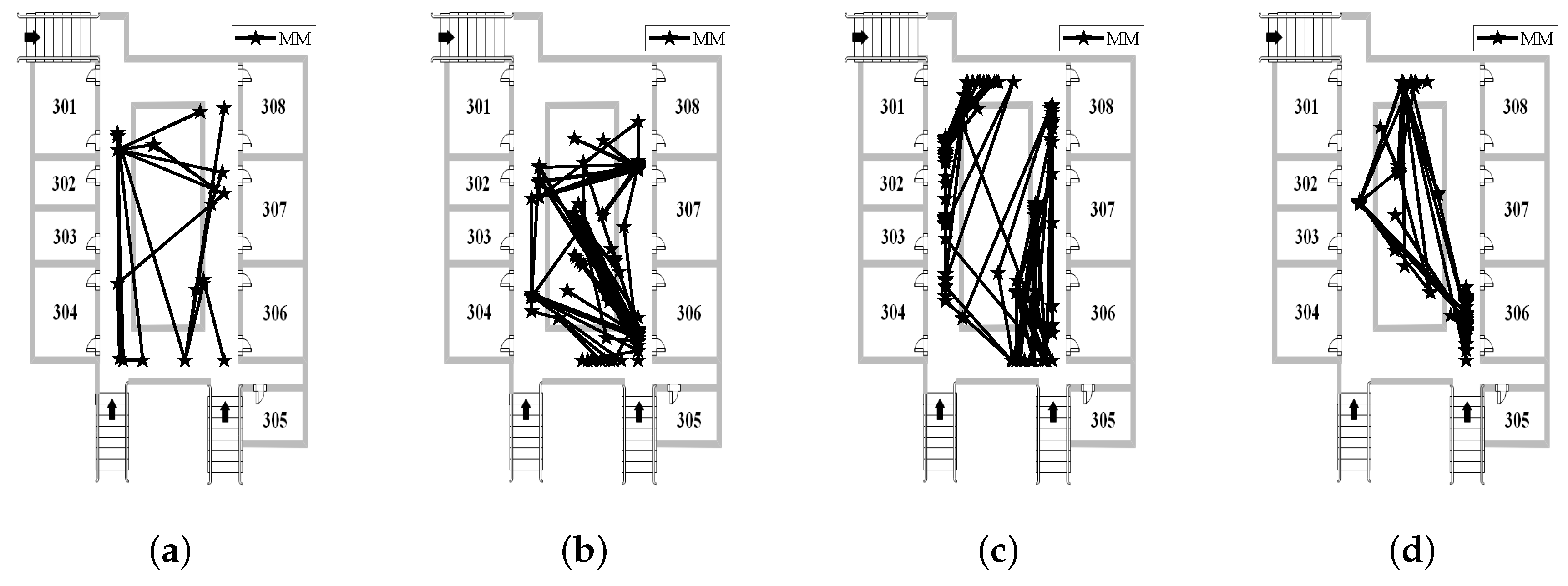
DTW is usually calculated the distance between the measured magnetic field and magnetic fingerprint in the database. For DR/MM, we creatively propose 3DDTW to calculate the distance. Unlike traditional DTW, 3DDTW extends the original one-dimensional signal to a two-dimensional signal.
(3)
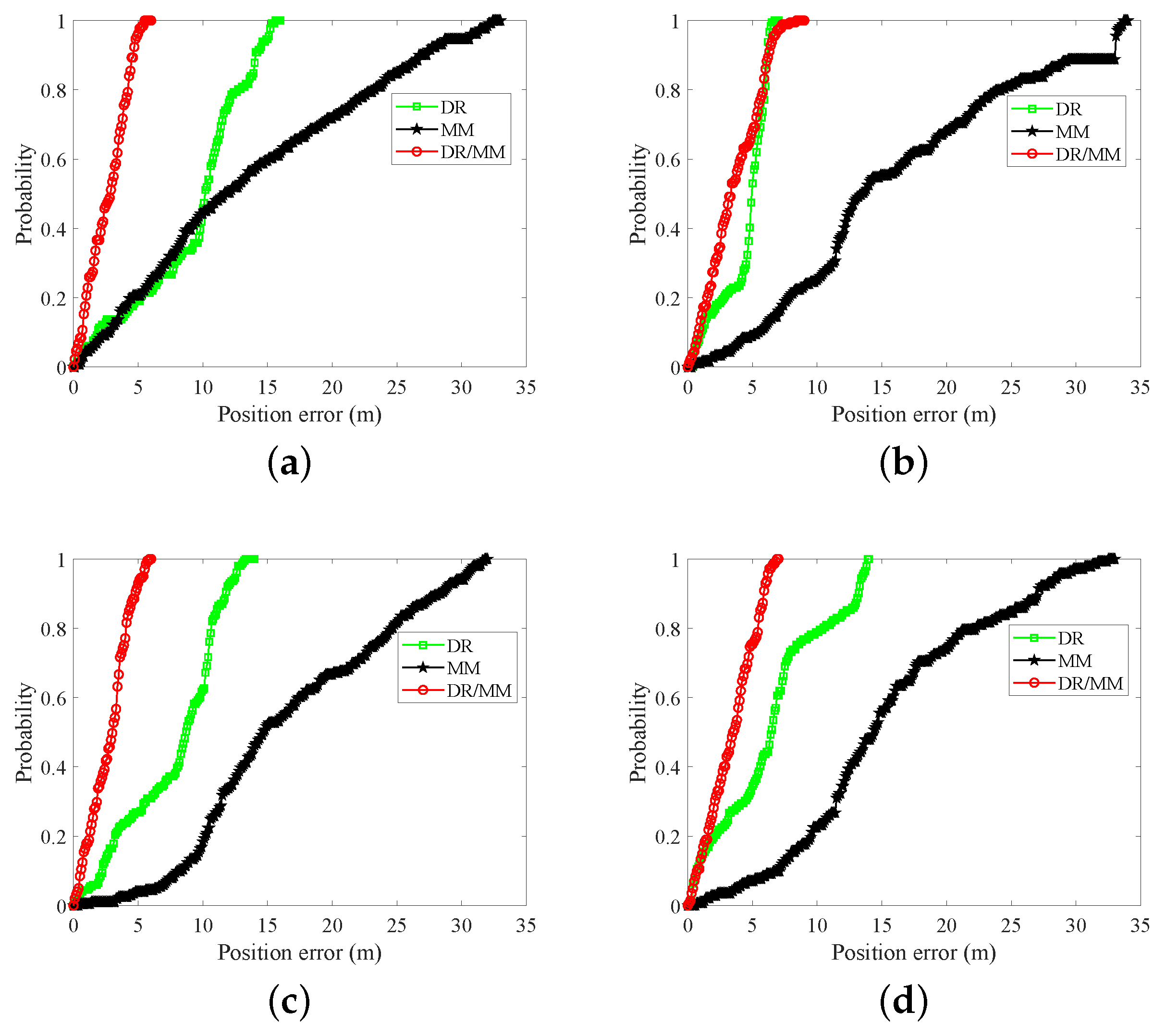
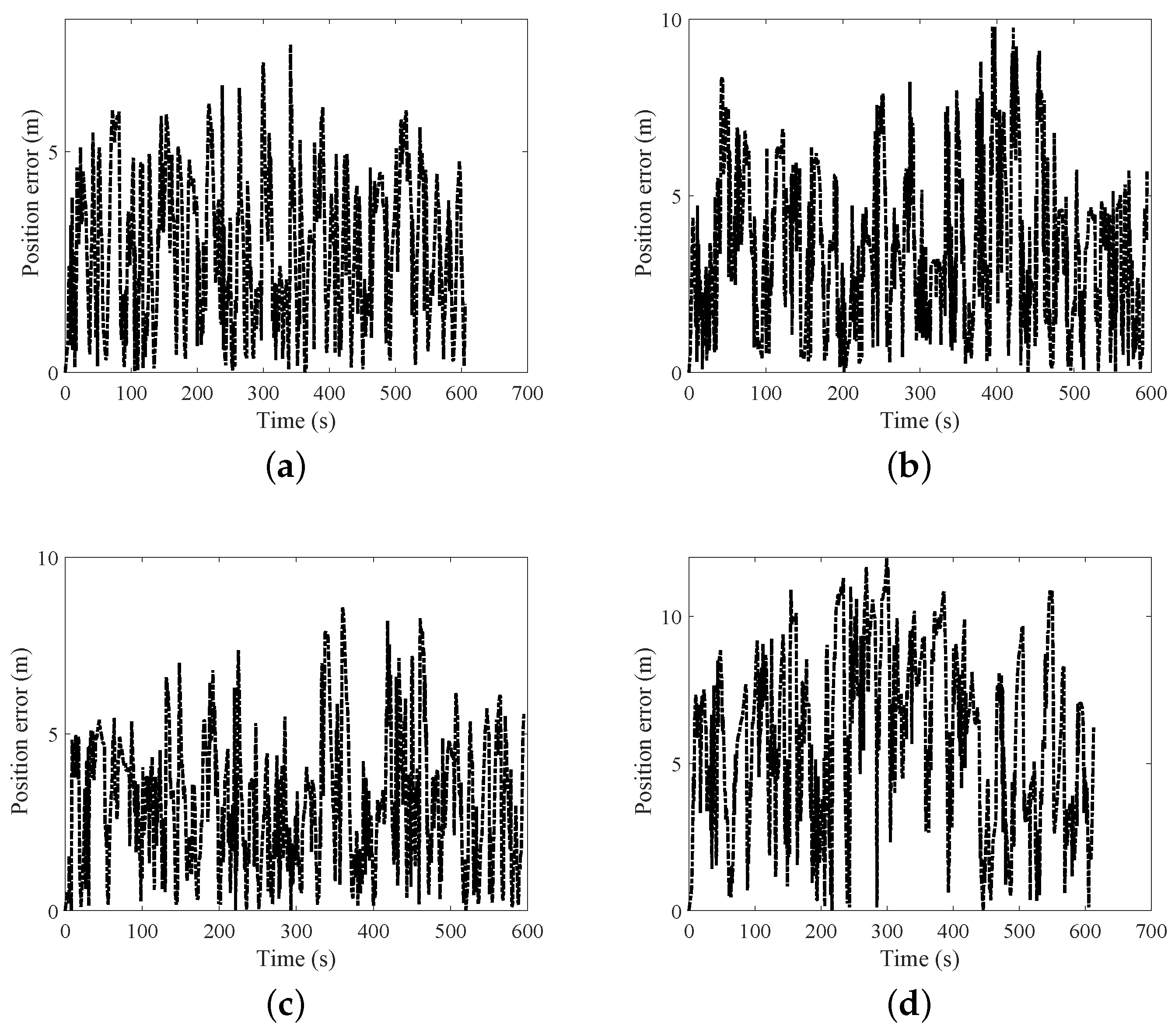
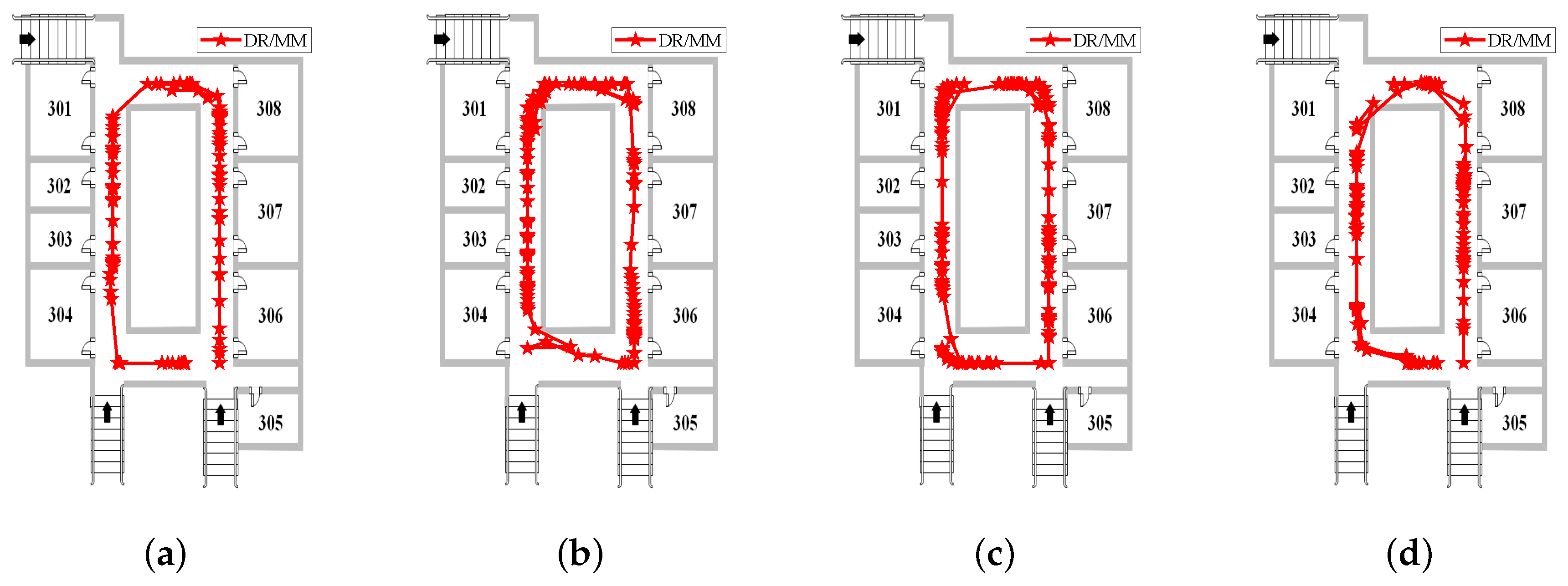
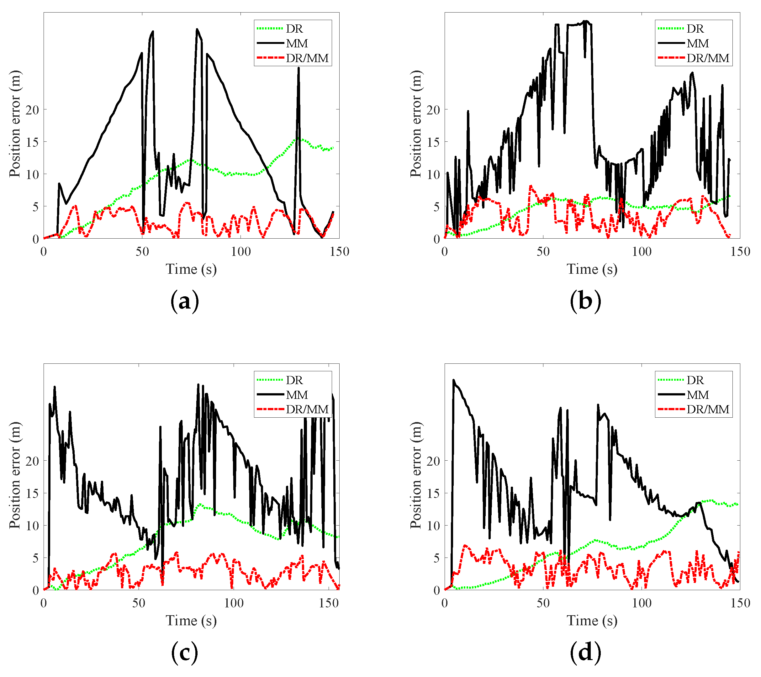
Many practical problems are considered in the DR/MM positioning system. The solutions to these problems further improve the positioning accuracy. For three different walking experiments, the average positioning accuracy is about 3.34 m.
The rest of the paper is organized as follows: We review the related work in Section 2. We introduce the system model in detail in Section 3. Walking experiments to test different scenes are discussed in Section 4. The conclusion and future work are presented in Section 5.

3. System Model

Figure 1 shows the overall structure of system model including DR module, DR/MM module. In DR module, the user’s attitude angle is estimated by integrating gyroscope reading. Step length and step counting are calculated from the accelerometer and gravitational acceleration. DR module calculates the user’s position. In DR/MM module, the magnetic field is converted from the body coordinate system to the navigation coordinate system. Then, we use 3DDTW to calculate the distance between the measured magnetic field and the fingerprint. Finally, the weighted least squares further improves indoor positioning accuracy.
Figure 1. The structure of system model.

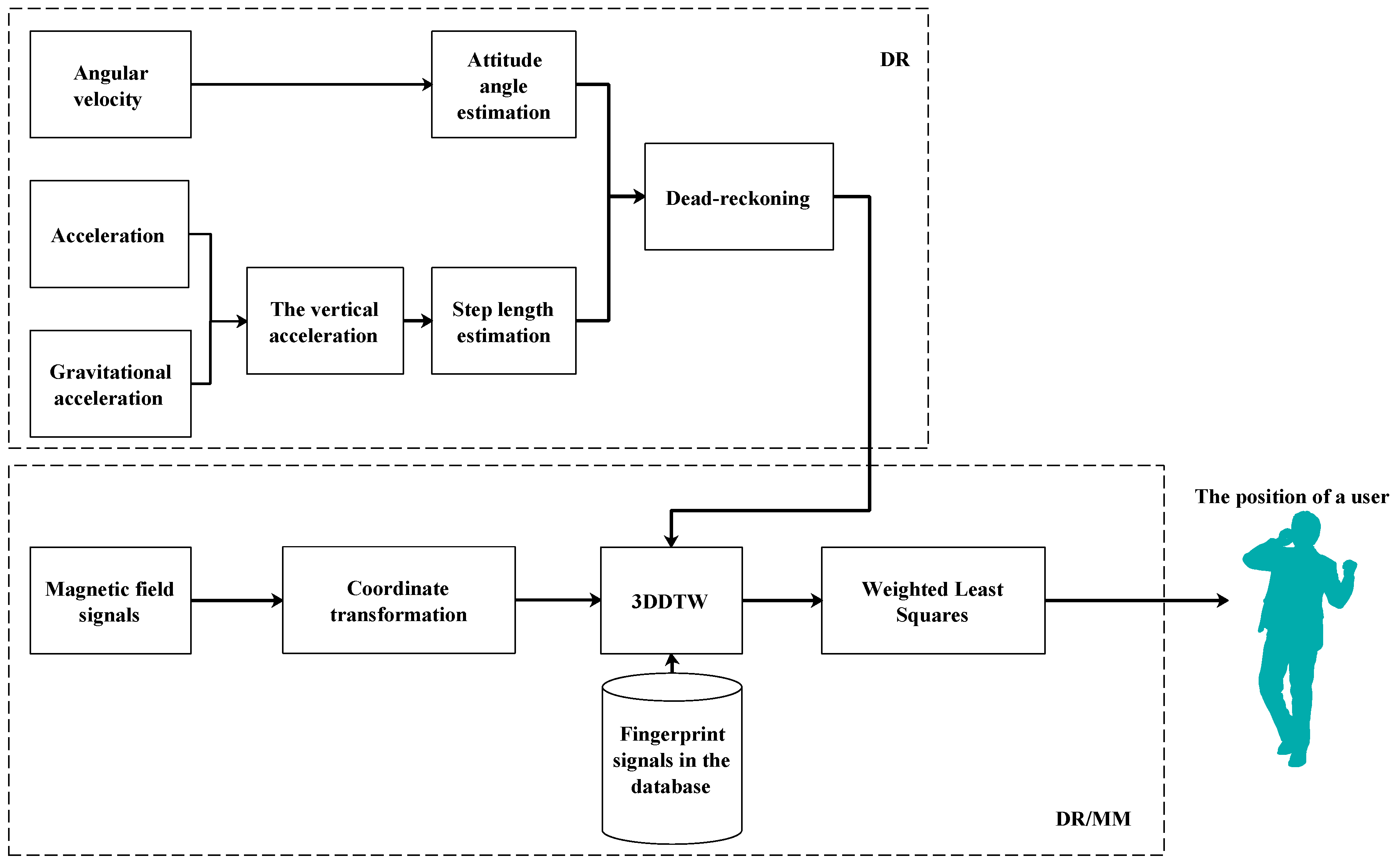
3.1. Dead-Reckonging

3.1.1. Attitude Angle Estimation Model

We use gyro reading to estimate the attitude of smartphone. Direct cosine matrix (DCM), quaternion, and Euler angle are the main techniques. The quaternion vector q = [ q 1 , q 2 , q 3 , q 4 ] is updated using the angular rate measurements from gyroscope reading. Then, the updated quaternion is used to get an attitude of the navigation system in terms of Euler angle. In [25], the relationship between DCM and quaternion is expressed as
C b n = q 1 2 q 2 2 q 3 2 + q 4 2 2 q 1 q 2 2 q 3 q 4 2 q 1 q 3 + 2 q 2 q 4 2 q 1 q 2 + 2 q 3 q 4 q 1 2 + q 2 2 q 3 2 + q 4 2 2 q 2 q 3 2 q 1 q 4 2 q 1 q 3 2 q 2 q 4 2 q 2 q 3 + 2 q 1 q 4 q 1 2 q 2 2 + q 3 2 + q 4 2
The attitude angle [ ϑ , ϕ , ψ ] in terms of DCM can be calculated as follows [25]
ϑ = tan 1 C b n ( 3 , 1 ) ( C b n ( 3 , 2 ) ) 2 + ( C b n ( 3 , 3 ) ) 2 ϕ = tan 1 C b n ( 3 , 2 ) C b n ( 3 , 3 ) ψ = tan 1 C b n ( 2 , 1 ) C b n ( 1 , 1 )
where c b n ( m , k ) is the mth row and the kth column element in the matrix ( c b n ). Roll, pitch and yaw from the smartphone are ϑ , ϕ and ψ .

3.1.2. Step Length Model

Each user’s step length is affected by mood, height, body weight, age, environment, and walking time. Therefore, a fixed step length is not appropriate. Different users have different step lengths. The estimated step length needs one or more training values to calibrate in the training step length model [26]. A linear step length model is developed using walking frequency and acceleration variance [27,28]. Another nonlinear step length model is one in which the vertical acceleration is segmented and analyzed to estimate step length. An empirical relation between vertical acceleration and step length is given by [29] as follows
S L = K a m a x a m i n 4
where, during one step, a m a x and a m i n are the maximum and minimum vertical acceleration, respectively. K is a calibration parameter, which adjusts step length estimation to a specific user. Different users require different empirical parameters, and this is the main disadvantage. The reliability of the model depends on the calibration parameters.
Step length is calculated using the triangle model [30]. The distance of the smartphone from the ground is L when the user is stationary. The distance of the smartphone from the ground is (L-H) when the user is walking. The vertical displacement of the smartphone (H) is calculated as follows
H = t 1 t 2 t 1 t 2 a z d t d t
where the start and end times of each step are t 1 and t 2 ; the vertical acceleration is a z . Based on the Pythagorean theorem, step length is calculated according to [30] as follows
S L = 2 L 2 ( L H ) 2

3.1.3. Step Counting Model

The vertical acceleration has a certain periodicity during walking. In general, the number of steps is estimated by detecting the peak of the vertical acceleration. Two peak points are treated as one step. Vertical acceleration is calculated as follows
a z = ( a g ) · g | g |
where acceleration and gravitational acceleration are a and g . When a vertical acceleration is greater than the previous value and less than the latter value, a peak is detected. Due to noise, one shortcoming is that many false peaks are detected, which lead to overload statistics. False peaks are removed using a variance technique. Therefore, two detection techniques, defined as follows, are designed to estimate the exact number of steps
R 1 ( k ) = 1 a z ( k ) > a z ( k 1 ) & a z ( k ) > a z ( k + 1 ) 0 o t h e r
R 2 ( k ) = 1 a z _ v a r ( k ) > T H D 0 o t h e r
where the vertical acceleration variance is a z _ v a r . A threshold (THD) is a constant. In this paper, detection results, expressed as follows, are the logical results of the two detection conditions.
R = R 1 R 2
where R indicates that the vertical displacement of a user during walking is unlikely to be too small.

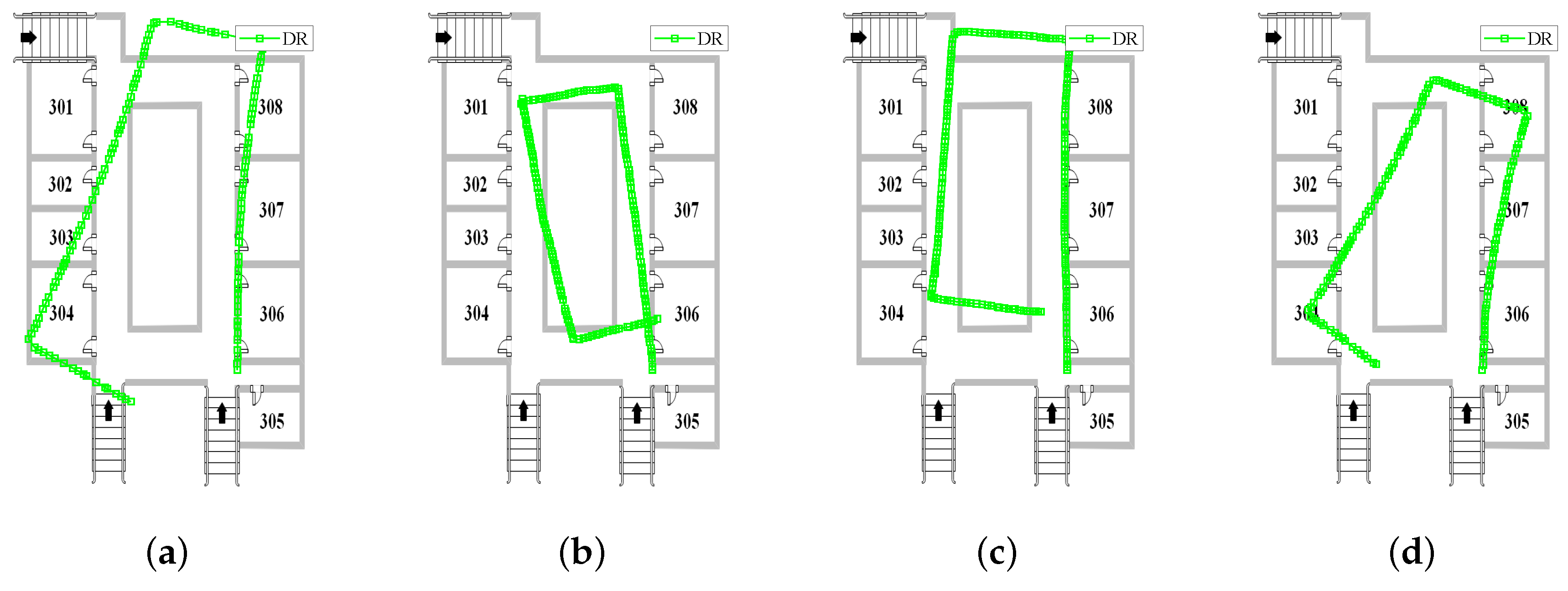
3.1.4. DR-Based Position Path

The heading from the attitude angle, step length and step counting determine the user’s path. DR updates the new position [ x k + 1 , y k + 1 ] T based on a previous position [ x k , y k ] T , step length and attitude, as Equation (10) expressed.
x k + 1 y k + 1 = x k y k + S L · cos ψ sin ψ

3.2. Dead-Reckoning and Magnetic Matching (DR/MM)

For the DR/MM positioning system, the first step is to construct a magnetic fingerprint database. The collection mode of magnetic field fingerprint is referenced in literature [16]. To collect magnetic field fingerprints, users, carrying smartphones, walk from the starting point to the end point. The fingerprints are stored in the database as < p o s i i , m i i > . The subscript i i represents the i i t h fingerprint in the database. The second step is to calculate the user’s position by DR. DR constrains the range of MM. Fifteen meters is used as the range of the MM. The third step is to use the measured magnetic field to match the fingerprints. The proposed DTW (3DDTW) is designed to calculate the distance between the measured magnetic field and the magnetic fingerprints. Finally, the weighted least squares is used to improve indoor localization accuracy and robustness.

3.2.1. Dynamic Time Warping (DTW) for DR/MM

The magnetic field corresponding to each step is treated as a measured value. Each fingerprint represents a path from the beginning to the end. To extract the position corresponding to a measured value, each fingerprint is cut into many small fingerprints. The distance between measured magnetic field and small fingerprint is calculated using DTW [31]. For the magnetic fingerprint, the DTW distance ( D ) is expressed as Equation (11).
d ( i , j ) = ( m m e a ( i ) m d b ( j ) ) 2 D ( i , j ) = d ( i , j ) + m i n ( [ D ( i 1 , j ) , D ( i 1 , j 1 ) , D ( i , j 1 ) ] )
where M m e a ( i ) and M d b ( j ) are the i t h measured magnetic field and the j t h fingerprint in the database, respectively. d denotes the square of Euclidean distance among pairs of values in M m e a and M d b ;

3.2.2. 3-Dimensional Dynamic Time Warping (3DDTW) for DR/MM

Traditional DTW requires that the input signal be a one-dimensional signal. A simple strategy is to use the amplitude of the magnetic field as the input signal. It is obvious that the one-dimensional signal reduces the three-dimensional magnetic field characteristics, which is not conducive to fingerprint matching. Directly using a magnetic field from a smartphone as a fingerprint is clearly unreasonable because the attitudes from the fingerprint construction phase and the magnetic field matching phase are difficult to maintain the same [32]. An effective method is to transform the magnetic field in the body frame into the navigation frame, as Equation (12) denotes.
m n x m n y m n z = C b n m b x m b y m b z
where the three-dimensional magnetic field reading in the navigation frame and the body frame are [ m n x , m n y , m n z ] T and [ m b x , m b y , m b z ] T , respectively.
Unlike traditional DTW, 3DDTW extends the original one-dimensional signal to a two-dimensional signal. In Figure 2, the left side represents the measured magnetic field ( m m e a ); the bottom surface represents the fingerprint ( m d b ). D represents the 3DDTW distance between the measured magnetic field and fingerprint in the database. Based on the idea of dynamic programming, the 3DDTRW distance at the current moment is equal to the newly added distance plus the distance from the previous moment. Therefore, the 3DDTW process is divided into two steps. The first step is to calculate the newly added distance between the measured magnetic field ( m m e a ( k , i ) ) and the fingerprint ( m d b ( k , j ) ), as Equation (13) expressed.
d ( i , j , k ) = ( m m e a ( k , i ) m d b ( k , j ) ) 2
Figure 2. 3DDTW distance calculation diagram.
In the three-dimensional coordinate system, the 3DDTW distances at the previous moment are D ( i 1 , j , k ) , D ( i , j 1 , k ) , D ( i , j , k 1 ) , D ( i 1 , j 1 , k ) , D ( i , j 1 , k 1 ) , D ( i 1 , j , k 1 ) , D ( i 1 , j 1 , k 1 ) , respectively. To search for the best alignment between two signals, the second step is calculated as Equation (14) expressed
D ( i , j , k ) = d ( i , j , k ) + m i n [ D ( i 1 , j , k ) , D ( i , j 1 , k ) , D ( i , j , k 1 ) , D ( i 1 , j 1 , k ) , D ( i , j 1 , k 1 ) , D ( i 1 , j , k 1 ) , D ( i 1 , j 1 , k 1 ) ]
Algorithm 1 shows the 3DDTW calculation process. In MM, the traditional DTW calculates the distance between the two magnetic signals by means of dimensionality reduction. It is obvious that the dimension reduction method reduces the characteristics of the magnetic field. 3DDTW calculates between two magnetic field signals by extending the dimension, which enhances the robustness of indoor positioning.
Algorithm 1 3DDTW
Input: The measured signal m m e a with p rows and n columns, fingerprint signal m d b with p rows and m columns.
  • Let d denote the distance among pairs of values in m m e a and m d b .
  • for i = 1 to n do
  •    for j = 1 to m do
  •       for k = 1 to p do
  •           d ( i , j , k ) = ( m m e a ( k , i ) m d b ( k , j ) ) 2
  •       End for
  •    End for
  • End for
  • Let D denote 3DDTW fingerprint distance from m m e a and m d b .
  • D ( 1 , 1 , 1 ) = d ( 1 , 1 , 1 )
  • for i = 2 to n do
  •    for j = 2 to m do
  •       for k = 2 to p do
  •        D ( 1 , 1 , k ) = d ( 1 , 1 , k ) + D ( 1 , 1 , k 1 )
  •        D ( i , 1 , 1 ) = d ( i , 1 , 1 ) + D ( i 1 , 1 , 1 )
  •        D ( 1 , j , 1 ) = d ( 1 , j , 1 ) + D ( 1 , j 1 , 1 )
  •        D ( 1 , j , k ) = d ( 1 , j , k ) + m i n [ D ( 1 , j 1 , k ) , D ( 1 , j , k 1 ) , D ( 1 , j 1 , k 1 ) ]
  •        D ( i , 1 , k ) = d ( i , 1 , k ) + m i n [ D ( i 1 , 1 , k ) , D ( i , 1 , k 1 ) , D ( i 1 , 1 , k 1 ) ]
  •        D ( i , j , 1 ) = d ( i , j , 1 ) + m i n [ D ( i 1 , j , 1 ) , D ( i , j 1 , 1 ) , D ( i 1 , j 1 , 1 ) ]
  •        D ( i , j , k ) = d ( i , j , k ) + m i n [ D ( i 1 , j , k ) , D ( i , j 1 , k ) , D ( i , j , k 1 ) , D ( i 1 , j 1 , k ) , D ( i , j 1 , k 1 ) , D ( i 1 , j , k 1 ) , D ( i 1 , j 1 , k 1 ) ]
  •       End for
  •    End for
  • End for
  • Output: The 3DDTW distance D .

3.2.3. Weighted Least Squares for DR/MM

The weighted least squares is an effective technique to improve positioning accuracy. Referring to the weighted least squares of Reference [16], we use similar technique to improve indoor positioning accuracy. The 3DDTW distances ( D = [ D 1 , D 2 , , D r ] ) and corresponding positions ( [ x ˜ 1 , y ˜ 1 ] T , [ x ˜ 2 , y ˜ 2 ] T , , [ x ˜ r , y ˜ r ] T ) are selected to estimate a user’s location. Based on the idea of linear weighting, a user’s position is estimated as follows
x ^ y ^ = ω 1 x 1 ˜ y 1 ˜ + ω 2 x 2 ˜ y 2 ˜ + + ω i x i ˜ y i ˜ + + ω r x r ˜ y r ˜
1 = ω 1 + ω 2 + + ω r
where ω i represents a weighting factor.
we construct the weighted least squares objective function is designed as follows
F = ω 1 x y x ˜ 1 y ˜ 1 2 + ω 2 x y x ˜ 2 y ˜ 2 2 + + ω r x y x ˜ r y ˜ r 2 m i n
where | | · | | is the Euclidean distance; [ x , y ] T is the real position.
We assume that the position error and the 3DDTW distance construct a linear relationship, as Equation (18) expressed
Δ z i = σ D i
where the position error Δ z i is expressed as [ x , y ] T [ x ˜ i , y ˜ i ] T ; σ represents a configuration factor.
Bring Equation (18) into Equation (17), using the Lagrange function [33], the expressions of ω i is calculated as follows
ω i = 1 D i 2 1 D 1 2 + · · · + 1 D r 2

4. Experiments and Discussions

We use Mi5 smartphone to build magnetic fingerprint database. Nexus5 smartphone is used to perform walking experiments. When the user walks, the smartphone maintains four motion gestures, including calling, dangling, handheld, and pocket. Walking experiments in three different scenarios were carried out in Xiamen University, as shown in Figure 3. The first experimental scenario consists of metal doors, metal windows, and a small number of students walking. The second experimental scenario consists of bookshelves, concrete columns, and many students. The third experimental scene consists of a metal fence and many metal doors. The magnetic field mean of three different environments are 123 μ T, 113.75 μ T and 117.74 μ T, respectively. Experimental results from three different walking trajectories are presented in this section.
Figure 3. Different scenarios.

4.1. Walking Experiment in Teaching Building

A walking positioning experiment was performed with the smartphone maintaining four motion gestures. The user walked about 90 m. The DR cannot eliminate heading drift, which results in error accumulation. Therefore, as seen in Figure 4, the cumulative errors from DR increase over time in the four motion gestures. Figure 5 shows that mismatching is a major problem in MM even though k-nearest neighbor is used to reduce the positioning error. Magnetic field mismatches lead to excessive positioning results in some areas. The DR and MM positioning results are diverged from the true trajectories on some occasions. As seen in Figure 6, integrated DR/MM technology reduces the mismatch by limiting the matching range. 3DDTW enhances the performance of magnetic field matching by extending the dimensions of the input signal. Weighted least squares further reduces positioning errors by linear weighting. Thus, integrated DR/MM technology improves positioning accuracy.
Figure 4. Positioning results for DR in teaching building: (a) calling; (b) dangling; (c) handheld; and (d) pocket.
Figure 5. Positioning results for MM in teaching building: (a) calling; (b) dangling; (c) handheld; and (d) pocket.
Figure 6. Positioning results for DR/MM in teaching building: (a) calling; (b) dangling; (c) handheld; and (d) pocket.
The position errors and the cumulative distribution function (CDF) curves are shown in Figure 7 and Figure 8. It can be seen from Figure 7 that in the initial stage, the inertial navigation positioning result is better than fusion positioning results in the four gestures. The main reason is that the inertial navigation system error has a cumulative effect, which is small at the beginning stage and increases with increase of walking time. Since the fluctuation of the magnetic field depends on the change of the environment, in the global matching range, the mismatch of the magnetic field reaches a large error, as shown by the black line in Figure 7. In most cases, integrated positioning system performance is superior to DR and MM in four gestures. The fusion positioning system uses the inertial navigation results to constrain the magnetic field matching range, while 3DDTW and weighted least squares improve the magnetic field matching performance. At less than 3 m, probability for DR, MM and DR/MM are as follows: 13.74%, 12.21% and 53.43%, respectively in calling gesture (see Figure 8a); 21.22%, 4.47% and 44.13%, respectively in dangling gesture (see Figure 8b); 16.41%, 1% and 49.75%, respectively in handheld gesture (see Figure 8c); 23.94%, 3.52% and 42.96%, respectively in pocket gesture (see Figure 8d). The positioning results indicate DR/MM integrated algorithm is robust to different motion gestures.
Figure 7. Position errors with different gestures in teaching building: (a) calling; (b) dangling; (c) handheld; and (d) pocket.
Figure 8. CDFs with different gestures in teaching building: (a) calling; (b) dangling; (c) handheld; and (d) pocket.
The average error, root mean square error (RMSE), maximum error, and circular error probability (CEP) for the four motion gestures are shown in Table 1. As expected, the smallest average positioning error in the four motion gestures, which is 3.09 m, belongs to DR/MM, and the average positioning errors for DR, and MM are 6.95 and 15.43 m, respectively. In comparison with DR, the average error, RMSE, maximum error, CEP (75%) and CEP (95%) for DR/MM are reduced by 47.28%, 49.21%, 50.32%, 42.12%, and 54.34%, respectively. In comparison with MM, the average error, RMSE, maximum error, CEP (75%) and CEP (95%) for DR/MM are reduced by 77.94%, 77.3%, 78.79%, 76.05%, and 78.45%, respectively.
Table 1. Position errors for DR, MM and DR/MM (m) in teaching building.

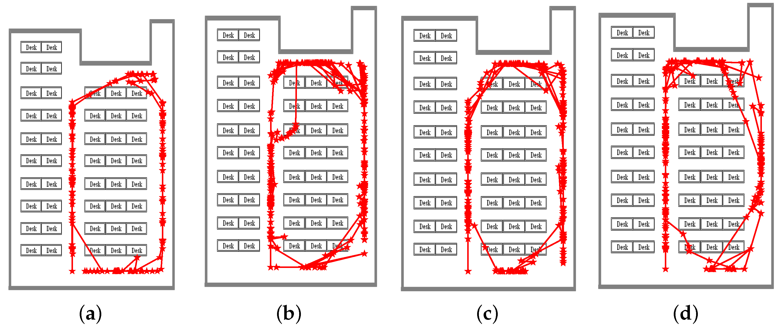
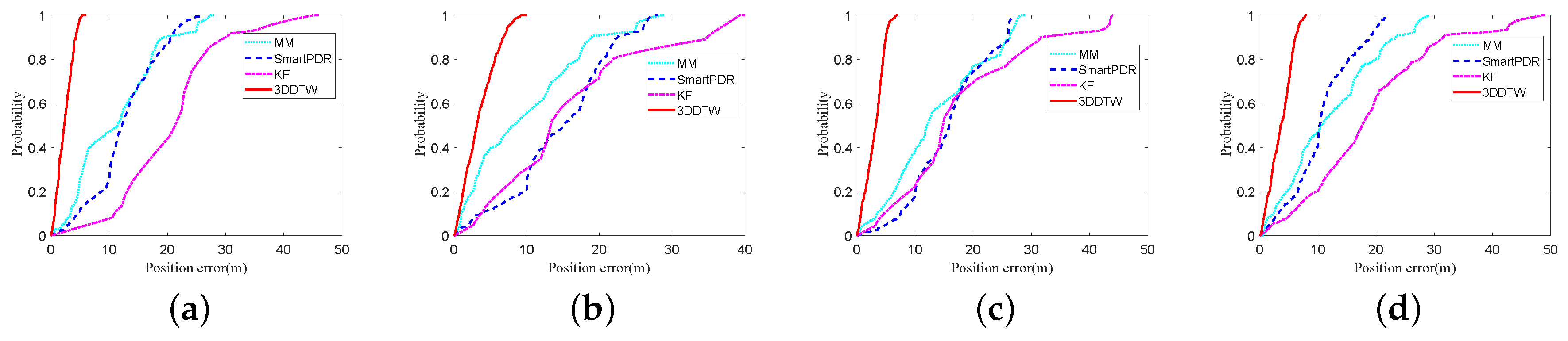
4.2. Walking Experiment in Study Room

A study room experiment was carried out to verify the effectiveness of our proposed algorithms. The walking distance was about 140 m. The positioning results of the four motion gestures for a smartphone are shown in Figure 9. The average errors in the four gestures for the walking experiment are 2.34, 3.48, 3.05 and 3.6 m, respectively. Reference [10] describes how to use the magnetic field alone to MM for indoor positioning. In the offline phase, the localization area is divided into many grids, and a magnetic field is acquired at each grid point. In the positioning phase, the collected magnetic field is used to match the magnetic fingerprint to obtain the user’s position. Reference [34] introduces a smart indoor positioning system (SmartPDR), which uses the magnetic field and gyroscope to estimate a user direction. In [30,35], Kalman Filter (KF) is used to reduce static moment error, but the cumulative error continues to expand over time. Figure 10 shows CDFs of four algorithms. At less than 3 m, the probabilities for MM, SmartPDR, KF, and 3DDTW are as follows: (a) for calling: 4.74%, 2.31%, 8.06%, and 65.88%, respectively; (b) for dangling: 9.22%, 6.7%, 25.53%, and 47.52%, respectively; (c) for handheld: 2.05%, 4.24%, 7.53%, and 46.23%, respectively; (d) for pocket: 9.43%, 5.97%, 14.75%, and 40.98%, respectively. 3DDTW obtains satisfactory positioning performance under four gestures.
Figure 9. Positioning results for DR/MM in study room: (a) calling; (b) dangling; (c) handheld; and (d) pocket.
Figure 10. CDFs for MM, SmartPDR, KF, 3DDTW in study room: (a) calling; (b) dangling; (c) handheld; and (d) pocket.
For MM, SmartPDR, KF, and 3DDTW, the average error, RMSE, maximum error, CEP (75%), and CEP (95%) are shown in Table 2. Compared with MM, SmartPDR, and KF, the errors of 3DDTW are reduced as follows: 66.13%, 80.68%, and 69.9% for the average error, respectively; 65.4%, 80.93%, and 71.26% for RMSE, respectively; 64.17%, 83.8%, and 72.87% for maximum error, respectively; 62.7%, 78.94%, and 69.53% for CEP (75%), respectively; 67.05%, 84.41%, and 75.09% for CEP (95%), respectively; The best positioning technology belongs to 3DDTW.
Table 2. Position errors for MM, SmartPDR, KF, and 3DDTW (m) in study room.

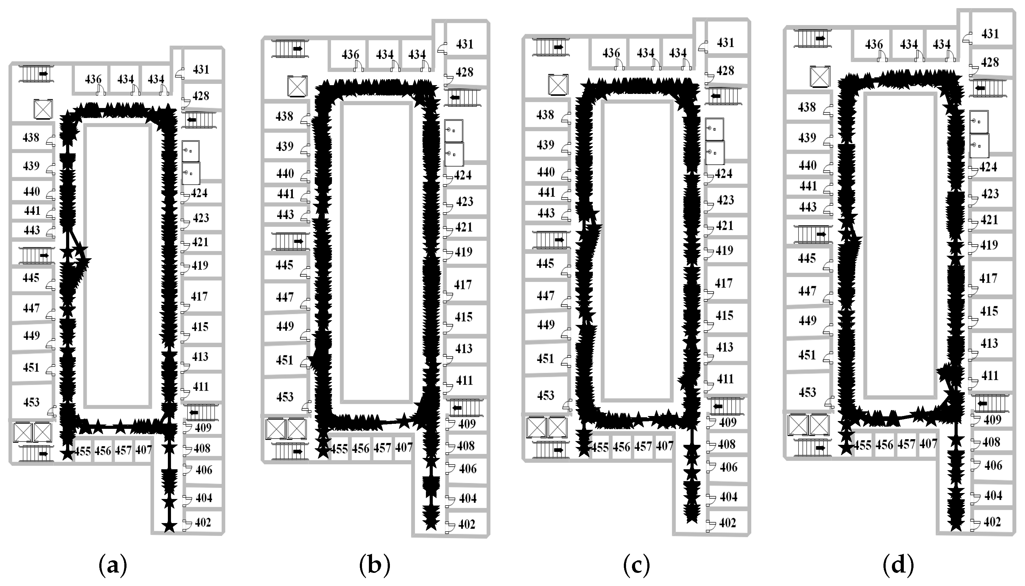
4.3. Walking Experiment in Office Building

A more complicated walking trajectory experiment was performed in office building. The walking distance was about 390 m. The pictures in Figure 11 illustrate the positioning results of four different gestures (calling, dangling, handheld and pocket) for office building; the pictures in Figure 12 show the corresponding position errors. As shown in Figure 11, the integrated positioning system still achieves satisfactory positioning results under a complicated walking path. In Figure 12, most of position errors in the four motion gestures are less than 10 m. The average errors in the four gestures for the walking experiment are 2.8, 3.47, 3.1 and 5.91 m, respectively. Figure 12 shows that the positioning errors from these four gestures are relatively stable. Experimental results show that the DR/MM hybrid algorithm improves positioning accuracy and robustness.
Figure 11. Positioning results for DR/MM in office building: (a) calling; (b) dangling; (c) handheld; and (d) pocket.
Figure 12. Position errors with different gestures in office building: (a) calling; (b) dangling; (c) handheld; and (d) pocket.
Table 3 shows the position errors for DR/MM in the office building. The pocket gesture error in the table is large, mainly due to the large jitter of smartphone. In general, the fusion algorithm proposed in this paper still obtains better positioning performance in the complex office building environment.
Table 3. Position errors for DR/MM (m) in office building.

5. Conclusions and Future Work

The above three walking experiments prove that our proposed algorithm effectively improves indoor positioning accuracy. First, we introduce attitude angle estimation, step length, and step counting models. Subsequently, DR estimates the user’s position based on acceleration and angular velocity. Second, the magnetic field in the body coordinate system is converted to the navigation coordinate system. Based on the traditional DTW, we propose an improved DTW (3DDTW) that extends a one-dimensional input signal into a two-dimensional input signal. 3DDTW is used to calculate the distance between the measured magnetic field and the fingerprint, which reduces the mismatch of the magnetic field fingerprint. Finally, a weighted least squares is used to further reduce indoor positioning error. The average errors from three walking experiments are 3.09, 3.12 and 3.82 m. The experimental results show that the integrated algorithm is stable, and it can adapt to different magnetic environment and different walking trajectories.
However, there are still some issues that need to be addressed further. Due to the changes of environment and time, the magnetic fingerprint database needs to be updated in real time. In addition, how to focus on the integration of more sensors of smartphones to improve positioning accuracy and robustness warrants further consideration.

Author Contributions

All authors contributed to this paper. J.C., G.O. and A.P. put forward the main algorithm. J.C. performed the walking experiments and wrote the paper. A.P., L.Z. and J.S. revised the paper.

Funding

This research was funded by the National Key Research and Development Program under Grant Number 2018YFB0505200.

Acknowledgments

We would like to express our great gratitude to Jiangfeng, as she helped us revise our paper by correcting some grammar mistakes and improving the level of language.

Conflicts of Interest

All authors declare no conflict of interest.

Abbreviations

The following abbreviations are used in this manuscript:
DRDead-Reckoning
MMMagnetic Matching
DTWDynamic Time Warping
3DDTW3-Dimensional Dynamic Time Warping
DCMDirect Cosin Matrix
CDFCumulative Distribution Function
RMSERoot Mean Square Error
CEPCircular Error Probability
KFKalman filter

References

  1. Wu, X.; Deng, F.; Chen, Z. RFID 3D-LANDMARC Localization Algorithm Based on Quantum Particle Swarm Optimization. Electronics 2018, 7, 19. [Google Scholar]
  2. Hall, D.L.; Narayanan, R.M.; Lenzing, E.H.; Jenkins, D.M. Passive Vector Sensing for Non-Cooperative Emitter Localization in Indoor Environments. Electronics 2018, 7, 442. [Google Scholar] [CrossRef]
  3. Sun, T.; Zheng, L.; Peng, A.; Tang, B.; Ou, G. Building information aided Wi-Fi fingerprinting positioning system. Comput. Electr. Eng. 2018, 71, 558–568. [Google Scholar] [CrossRef]
  4. Zhuang, Y.; Li, Y.; Lan, H.; Syed, Z.; El-Sheimy, N. Smartphone-based WiFi access point localisation and propagation parameter estimation using crowdsourcing. Electron. Lett. 2015, 51, 1380–1382. [Google Scholar] [CrossRef]
  5. Han, D.; Jung, S.; Lee, M.; Yoon, G. Building a practical Wi-Fi-based indoor navigation system. IEEE Pervasive Comput. 2104, 13, 72–79. [Google Scholar]
  6. Yu, C.; El-Sheimy, N.; Lan, H.; Liu, Z. Map-based indoor pedestrian navigation using an auxiliary particle filter. Micromachines 2017, 8, 225. [Google Scholar] [CrossRef] [PubMed]
  7. Chen, J.; Ou, G.; Peng, A.; Zheng, L.; Shi, J. An INS/Floor-Plan Indoor Localization System Using the Firefly Particle Filter. ISPRS Int. J. Geo-Inf. 2018, 7, 324. [Google Scholar] [CrossRef]
  8. Subbu, K.P.; Gozick, B.; Dantu, R. LocateMe: Magnetic-fields-based indoor localization using smartphones. ACM Trans. Intell. Syst. Technol. 2013, 4, 73. [Google Scholar] [CrossRef]
  9. Bachmann, E.R.; Yun, X.; Peterson, C.W. An investigation of the effects of magnetic variations on inertial/magnetic orientation sensors. In Proceedings of the 2004 IEEE International Conference on Robotics and Automation, New Orleans, LA, USA, 26 April–1 May 2004; pp. 1115–1122. [Google Scholar]
  10. Li, B.; Gallagher, T.; Dempster, A.G.; Rizos, C. How feasible is the use of magnetic field alone for indoor positioning? In Proceedings of the 2012 International Conference on Indoor Positioning and Indoor Navigation (IPIN), Sydney, NSW, Australia, 13–15 November 2012; pp. 1–9. [Google Scholar]
  11. Sheinker, A.; Ginzburg, B.; Salomonski, N.; Frumkis, L.; Kaplan, B.Z.; Moldwin, M.B. A method for indoor navigation based on magnetic beacons using smartphones and tablets. Measurement 2106, 81, 197–209. [Google Scholar] [CrossRef]
  12. Xie, H.; Gu, T.; Tao, X.; Ye, H.; Lv, J. MaLoc: A practical magnetic fingerprinting approach to indoor localization using smartphones. In Proceedings of the 2014 ACM International Joint Conference on Pervasive and Ubiquitous Computing, New York, NY, USA, 13–17 September 2017; pp. 243–253. [Google Scholar]
  13. Abdulrahim, K.; Hide, C.; Moore, T.; Hill, C. Using constraints for shoe mounted indoor pedestrian navigation. J. Navig. 2012, 65, 15–28. [Google Scholar] [CrossRef]
  14. Li, F.; Zhao, C.; Ding, G.; Gong, J.; Liu, C.; Zhao, F. A reliable and accurate indoor localization method using phone inertial sensors. In Proceedings of the 2012 ACM Conference on Ubiquitous Computing, Pittsburgh, PA, USA, 5–8 September 2012; pp. 421–430. [Google Scholar]
  15. Chen, Z.; Zhu, Q.; Soh, Y.C. Smartphone inertial sensor-based indoor localization and tracking with iBeacon corrections. IEEE Trans. Ind. Inform. 2018, 12, 1458. [Google Scholar] [CrossRef]
  16. Chen, J.; Ou, G.; Peng, A.; Zheng, L.; Shi, J. An INS/WiFi Indoor Localization System Based on the Weighted Least Squares. Sensors 2016, 18, 1458. [Google Scholar] [CrossRef] [PubMed]
  17. Jiménez, A.R.; Seco, F.; Prieto, J.C.; Guevara, J. Indoor pedestrian navigation using an INS/EKF framework for yaw drift reduction and a foot-mounted IMU. In Proceedings of the 2010 7th Workshop on Positioning Navigation and Communication (WPNC), Dresden, Germany, 11–12 March 2010; pp. 135–143. [Google Scholar]
  18. Chung, H.Y.; Hou, C.C.; Chen, Y.S. Indoor intelligent mobile robot localization using fuzzy compensation and Kalman filter to fuse the data of gyroscope and magnetometer. IEEE Trans. Ind. Eelectron. 2015, 62, 6436–6447. [Google Scholar] [CrossRef]
  19. Xie, H.; Gu, T.; Tao, X.; Ye, H.; Lu, J. A reliability-augmented particle filter for magnetic fingerprinting based indoor localization on smartphone. IEEE Trans. Mob. Comput. 2016, 15, 1877–1892. [Google Scholar] [CrossRef]
  20. Li, Y.; Zhuang, Y.; Lan, H.; Zhou, Q.; Niu, X.; El-Sheimy, N. A hybrid WiFi/magnetic matching/PDR approach for indoor navigation with smartphone sensors. IEEE Commun. Lett. 2016, 20, 169–172. [Google Scholar] [CrossRef]
  21. Tkhorenko, M.Y.; Pavlov, B.V.; Karshakov, E.V.; Volkovitsky, A.K. On integration of a strapdown inertial navigation system with modern magnetic sensors. In Proceedings of the 2018 25th Saint Petersburg International Conference on Integrated Navigation Systems (ICINS), St. Petersburg, Russia, 28–30 May 2018; pp. 1–4. [Google Scholar]
  22. Poulose, A.; Eyobu, O.S.; Han, D.S. An Indoor Position-Estimation Algorithm Using Smartphone IMU Sensor Data. IEEE Access 2019, 99, 1. [Google Scholar] [CrossRef]
  23. Klipp, K.; Rosé, H.; Willaredt, J.; Sawade, O.; Radusch, I. Rotation-Invariant Magnetic Features for Inertial Indoor-Localization. In Proceedings of the 2018 International Conference on Indoor Positioning and Indoor Navigation (IPIN), Nantes, France, 24–27 September 2018; pp. 1–10. [Google Scholar]
  24. Li, Y.; Zhuang, Y.; Lan, H.; Zhang, P.; Niu, X.; El-Sheimy, N. Self-Contained Indoor Pedestrian Navigation Using Smartphone Sensors and Magnetic Features. IEEE Sens. J. 2016, 16, 7173–7182. [Google Scholar] [CrossRef]
  25. Shin, E.H. Estimation Techniques for Low-Cost Inertial Navigation; UCGE Report; UCGE: Bursa, Turkey, 2005. [Google Scholar]
  26. Zhang, M.; Wen, Y.; Chen, J.; Yang, X.; Gao, R.; Zhao, H. Pedestrian dead-reckoning indoor localization based on OS-ELM. IEEE Access 2018, 6, 6116–6129. [Google Scholar] [CrossRef]
  27. Huang, C.; Zhang, G.; Jiang, Z.; Li, C.; Wang, Y.; Wang, X. Smartphone-based indoor position and orientation tracking fusing inertial and magnetic sensing. In Proceedings of the 2014 International Symposium on Wireless Personal Multimedia Communications (WPMC), Sydney, NSW, Australia, 7–10 September 2014; pp. 215–220. [Google Scholar]
  28. Huang, C.; He, S.; Jiang, Z.; Li, C.; Wang, Y.; Wang, X. Indoor positioning system based on improved PDR and magnetic calibration using smartphone. In Proceedings of the 2014 IEEE 25th Annual International Symposium on the Personal, Indoor, and Mobile Radio Communication (PIMRC), Washington, DC, USA, 2–5 September 2014; pp. 2099–2103. [Google Scholar]
  29. Davidson, P.; Piché, R. A survey of selected indoor positioning methods for smartphones. IEEE Commun. Surv. Tutor. 2017, 19, 1347–1370. [Google Scholar] [CrossRef]
  30. Zheng, L.X.; Wu, Z.H.; Zhou, W.C.; Weng, S.L.; Zheng, H.R. A Smartphone Based Hand-Held Indoor Positioning System. In Frontier Computing; Springer: Singapore, 2016; pp. 639–650. [Google Scholar]
  31. Subbu, K.P.; Gozick, B.; Dantu, R. Indoor localization through dynamic time warping. In Proceedings of the 2011 IEEE International Conference on Systems, Man, and Cybernetics (SMC), Anchorage, AK, USA, 9–12 October 2011; pp. 1639–1644. [Google Scholar]
  32. Wang, Q.; Luo, H.; Zhao, F.; Shao, W. An indoor self-localization algorithm using the calibration of the online magnetic fingerprints and indoor landmarks. In Proceedings of the 2016 International Conference on Indoor Positioning and Indoor Navigation (IPIN), Alcala de Henares, Spain, 4–7 October 2016; pp. 1–8. [Google Scholar]
  33. Simon, D.; Chia, T.L. Kalman filtering with state equality constraints. IEEE Trans. Aerosp. Electron. Syst. 2002, 38, 128–136. [Google Scholar] [CrossRef]
  34. Kang, W.; Han, Y. SmartPDR: Smartphone-based pedestrian dead reckoning for indoor localization. IEEE Sens. J. 2015, 15, 2096–2916. [Google Scholar] [CrossRef]
  35. Zheng, L.; Zhou, W.; Tang, W.; Zheng, X.; Peng, A.; Zheng, H. A 3D indoor positioning system based on low-cost MEMS sensors. Simul. Model. Pract. Theory 2016, 65, 45–56. [Google Scholar] [CrossRef]

Article Metrics

Citations

Article Access Statistics

Multiple requests from the same IP address are counted as one view.