Abstract
This paper focuses on the waveform design for a radar-embedded communication (REC) system which can achieve covert communication while improving the spectrum utilization. In order to solve the problem that the conventional embedded communication waveforms are not orthogonal, this paper proposes the orthogonal weighted-combining (OWC) strategy and the orthogonal dominant-projection (ODP) strategy. Furthermore, the OWC strategy can be broken into two strategies: constrained weighted-combining (CWC) strategy and improved weighted-combining (IWC) strategy. Theoretical analysis and simulation results have shown that these three strategies can dramatically improve communication reliability. Moreover, the performance of the strategies mentioned above has been assessed by the low probability of intercept (LPI) metric. Comparing to the traditional strategies, the IWC strategy shows better LPI performance while the CWC strategy and ODP strategy remain unchanged. Additionally, the ODP strategy can also reduce computational complexity and response delay, which is rather important in the REC system. Any of the three strategies can be selected in accordance with the needs of the application scenario.
1. Introduction
The expansion of users and the development of wireless devices have challenged the future military communication systems a lot. One challenge is that, with the increasing of wireless devices, spectrum resources become more and more shortage. In 2013, the US Defense Advanced Research Projects Agency (DARPA) set up a program named Shared Spectrum Access for Radar and Communications (SSPARC) [1] to develop spectrum-sharing technologies [2,3,4] between military radars and military communication systems, which is considered as an effective way of improving the spectrum utilization [5]. Radar-embedded communication (REC) [6] is a strong competitor amongst this program, it takes both the finite spectrum resource and the transmission security into consideration.
As shown in Figure 1, the operational concept of REC consists of four primary aspects. Firstly, an area is illuminated by radar, which may be friend or foe. Secondly, the radio frequency (RF) tag/transponder processes the received signal and embeds communication signal into radar signal of the same time and the same frequency to cover up the communication signal with the radar signal. Thirdly, the cooperative receiver detects and recovers the covert information transmitted by the RF tag. Finally, there may be an intercept receiver.
Figure 1.
Generic radar-embedded communication (REC) system.
To achieve covert communication in this manner, Shannon Blunt et al. discussed some pertinent technical issues (here we list three typical issues as follows. Firstly, the embedded communication waveforms should be designed based upon the incident radar waveform. Secondly, the cooperative receiver should extract and recover the embedded communication signal properly. Thirdly, it is necessary to make a trade-off between covertness and communication reliability.) and proposed a feasible strategy in their early papers [7,8]. Since eavesdroppers tend to concentrate more on the passband of radar spectrum, hiding the communication signal in the stopband seems to be a feasible solution (specifically, in the passband of radar spectrum, we make the communication signal as weak as possible. In the stopband, we make the communication signal sufficiently correlate with the radar signal.) to meet the target of REC. Compared with other spectrum sharing technologies (e.g., radar communication integration [9]), this method can achieve covert communication while improving the spectrum utilization. Compared with other covert communication technologies (e.g., physical layer security [10,11,12]), this method provides both low probability of detection (LPD) (the intercept receivers can easily ignore the communication signal. On the one hand, the energy of the communication signal can be much lower than that of the radar signal. On the other hand, the embedded communication signal hides in the stopband and possesses the similar spectrum characteristics with the radar signal.) and low probability of intercept (LPI) (even if the communication signal has been detected, the intercept receivers cannot extract the covert information without prior information.) performance. Therefore, REC has attracted the attention of many scholars and research institutions.
The Air Force Office of Scientific Research (AFOSR) and the Office of Naval Research (ONR) had planned to apply REC in engineering since 2009 [13]. A series of problems in engineering have been discussed by many scholars. The authors in [14] made in-depth research on the effect of multipath fading in the REC link. In order to offset the influence of multipath fading, the time reversal technique of REC was proposed in [15], which can further improve the LPI performance. However, this technique requires an accurate estimation of the channel, which may be a little short for practice. In [16], it was assumed that the radar waveform is known to the RF tag, then the estimation of the channel via coherent processing was proposed. In [17], a two-stage Neyman Pearson detector was presented, which can ensure the reliability of detection at the cooperative receiver. To assess the performance of the REC system, performance characteristics and metrics were discussed in [18].
To get a better balance between reliability and covertness, Domenico Ciuonzo et al. [19,20] proposed a waveform design procedure based on multi-objective optimization. For the expansion of the application, Chaoyun Mai et al. [21] proposed a method for sparse frequency waveform design. Baoguo Li et al. [22] investigated more complex waveform design based on the spread spectrum. Shan He et al. [23] made a hybrid combination of water filling and spectral shaping. An approach based on continuous phase modulation (CPM) was introduced for REC in [24], and characterization of range sidelobe modulation was discussed in [25]. In order to reduce complexity, Cenk Sahin et al. [26] proposed an alternative mathematical formulation, which decouples range and Doppler processing. Furthermore, some of the papers on radar communication integration are also applicable to REC, such as [9,27].
The design of REC waveform (i.e., the embedded communication) has always been the core technology in REC system. Traditional basic design strategies (although many scholars have tried to improve the REC waveform, there are only three basic design strategies, which are dominant-projection, weighted-combining and eigenvectors-as-waveforms. Eigenvectors-as-waveforms strategy is not covert, so we don’t consider it here. This paper focuses on the basic design strategies, and the existing work on REC waveform is equally applicable to our proposed strategies.) are dominant-projection (DP) and weighted-combining (WC). However, these two strategies do not fully consider the orthogonality between different waveforms, and the REC waveforms designed by them cannot be completely orthogonal. This problem will affect the performance of communication transmission and reduce reliability. For duplex design, the transmission reliability of the waveform is very important, which would determine whether the REC link can be established and extended to the networking application. This paper observes this problem and proposes improved strategies. In different application scenarios, we recommend different waveform design strategies to improve communication reliability and ensure covertness.
Note that part of the work in this paper was described in our previous conference paper [28]. As an extended version, we add the following parts, which are also the main contributions of this paper.
- We illustrate the design idea of REC specifically, and for the first time explain the reason why traditional methods convert the research target.
- We analyze the orthogonality of WC and DP strategies. The existing conclusions on REC wavefroms are summarized in this paper.
- We proposed the improved weighted-combining (IWC) strategy in the previous conference paper, which can improve the reliability and LPI performance simultaneously. Yet the IWC strategy does have a construction limit, and cannot generate a large number of different REC waveforms. To solve this problem, we recommend the constrained weighted-combining (CWC) strategy as an alternative. Integrating the IWC strategy with the CWC strategy, we propose the orthogonal weighted-combining (OWC) strategy based on WC.
- We propose the orthogonal dominant-projection (ODP) strategy on the basis of DP, which can ensure the orthogonality of REC waveforms and reduce the complexity as well. We can choose whether the ODP strategy or the OWC strategy according to practical needs.
- In order to show the advantage of our technique, we compare the proposed strategies and traditional ones in terms of communication reliability and LPI performance.
The remainder of this paper is organized as follows. Section 2 presents the preliminaries and system model. In Section 3, we introduce the traditional schemes which include REC waveform design strategies, receiver designs and performance metrics. We also analyze the orthogonality of WC and DP strategies in this section. The proposed orthogonal waveform design strategies and performance comparison are shown in Section 4. Simulation results are presented in Section 5 and final conclusions are presented in Section 6.
2. Preliminaries and System Model
2.1. Preliminaries
A list of notations will be used throughout the paper as follows.
- Lowercase and bold letters are used to denote vectors, i.e., .
- Uppercase and bold letters are used to denote matrices, i.e., .
- We also use the vectors to denote matrices, i.e., .
- stands for the space of vectors with complex elements.
- stands for the space of matrices with complex elements.
- stands for natural numbers.
- stands for the Hermit operator (conjugate transpose of matrix ).
- stands for the inverse of matrix .
- stands for a diagonal matrix composed of the diagonal elements .
- stands for the complex conjugate of complex number a.
- represents the identity matrix.
- represents the null matrix.
- represents the argument of the maximum.
- represents the expectation operator.
- represents the summation process.
- represents the square root.
- denotes matrix norm.
- denotes the absolute value.
- * denotes a convolution process.
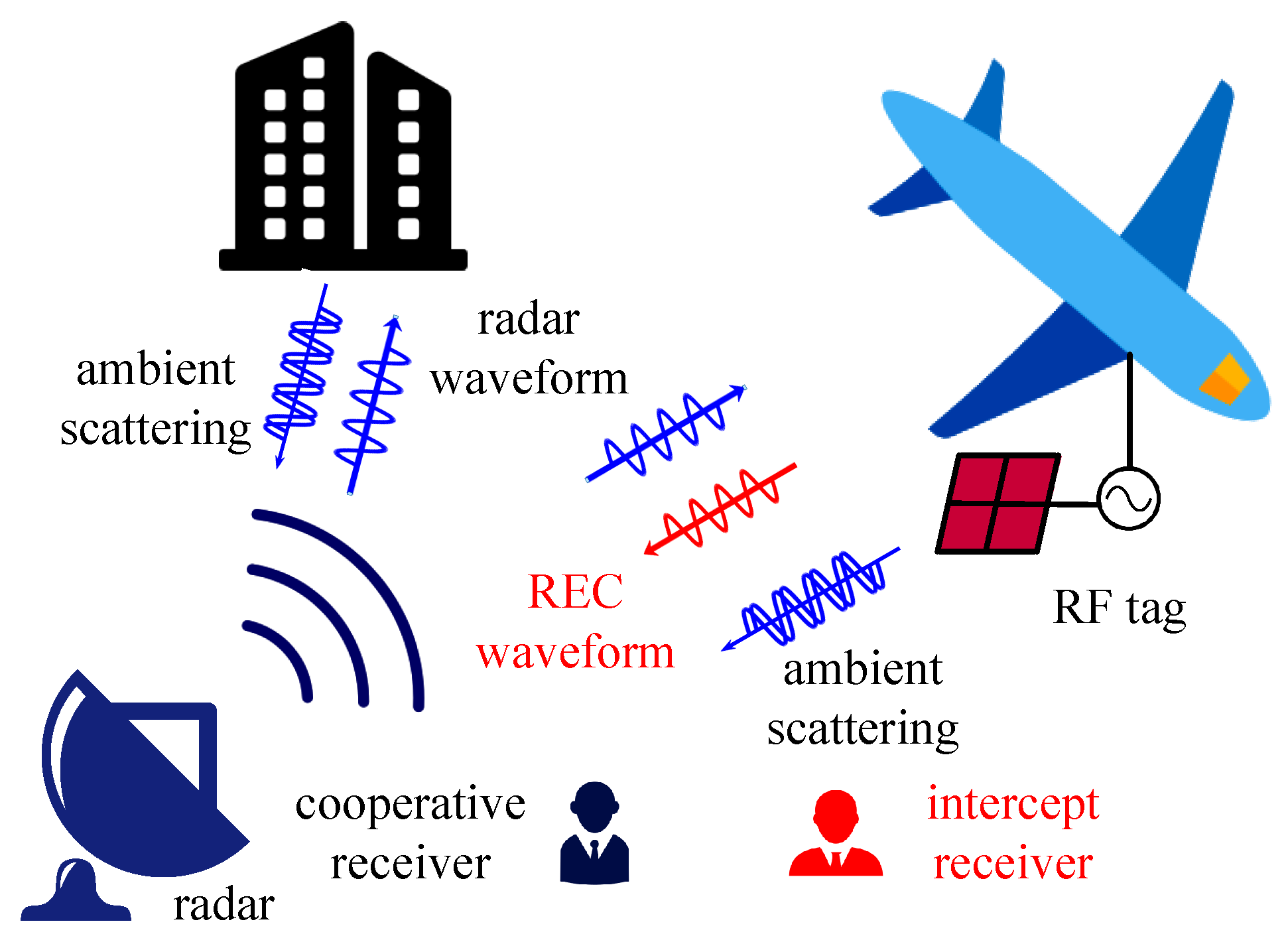
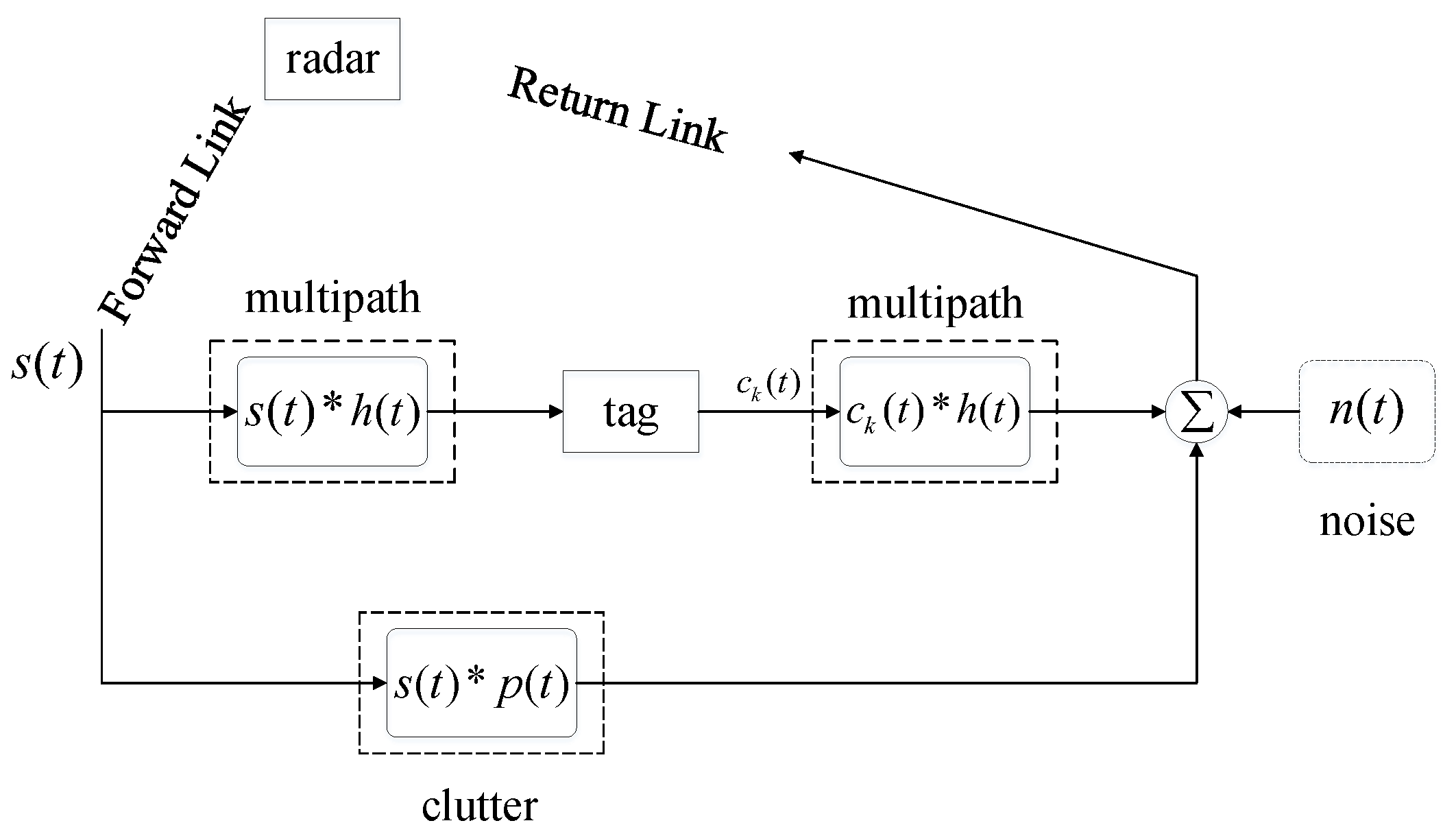
2.2. System Model
Assuming that the cooperative receiver is radar, the REC system model is shown in Figure 2. In the forward link, the radar signal is received by both the RF tag and radar target. In the backward link, the radar echo and the embedded REC signal return to radar. Specifically, we assume that the radar transmits linear frequency modulated (LFM) waveforms [29] and the signals are transmitted over an additive white Gaussian noise (AWGN) channel. Then the signal received by radar can be expressed as [22]
where represents the signal transmitted by radar, represents the clutter, or ambient backscatter, represents the multipath channel response, and represents the embedded REC signal. is an attenuation constant, and is the environmental noise. The interaction between radar signal and clutter is modeled as a convolution of and .
Figure 2.
Continuous time signal model [28].
Generally, we need to oversample (for higher design freedom, the RF tag and radar usually require more sampling points than the Nyquist sampling.) the received signals. We define that N is the number of sampling points which could satisfy the Nyquist criterion, and (for convenience, we take as a positive integer. ) is an oversampling factor, which means sampling at times of the Nyquist rate. Then the discrete oversampled radar signal can be denoted as the following vector with the length of [28]:
where are sampled data. Since the length of is , there are possible shifts when calculating the convolution. Therefore, the discrete convolution can be expressed as follows [28]:
where is a Toeplitz matrix corresponding to , is a clutter column vector. Although can be used to control the power of the embedded REC signal, we do not need to consider it during the waveform design phase [8].
The spectrum of LFM radar waveform is shown in Figure 3. We can see that most of the spectral components are distributed in the passband, while only a small amount of the spectral components are distributed in the stopband. Corresponding to the matrix , we can use the eigenvectors and eigenvalues to characterize . The larger the eigenvalue, the more information the corresponding eigenvector can be carried, and the higher the similarity with the radar waveform would be, vice versa.
Figure 3.
Spectrum of linear frequency modulated (LFM) radar waveform.
Eigen-decomposition can be used to obtain the eigenvalues and eigenvectors of the square matrices. However, is not a square matrix. Therefore, we cannot perform eigen-decomposition on directly. Instead, we perform singular value decomposition on as follows:
where and are unitary matrices, , are the r positive singular values of , and r represents the rank of . When radar transmits the LFM waveforms, r is equal to , and Equation (4) can be rewritten as
Here, the left singular value matrix is formed by standard orthogonal eigenvectors of , and the right singular value matrix is formed by standard orthogonal eigenvectors of . According to the physical meanings of singular value decomposition, left singular value matrix can be used to characterize the matrix [30]. Therefore, traditional methods perform eigen-decomposition on to obtain the matrix [8]:
where represents the diagonal matrix consisted of the eigenvalues, represents the unitary matrix composed of the associated eigenvectors, and are column vectors. We assume that the eigenvalues in are in the order of increasing magnitude. The above theoretical analysis explains the reason why traditional methods convert the research target as .
Figure 4 shows the eigenvalues of LFM radar signal at oversampling factors of , and respectively. N equals to 100. Since the eigenvalues are arranged in the order of increasing magnitude, we can define the last L eigenvalues as the dominant region and the remaining eigenvalues as the non-dominant region. Similarly, we can define the eigenvectors corresponding to the dominant region as dominant eigenvectors and the eigenvectors corresponding to the non-dominant region as non-dominant eigenvectors. The size of the dominant region is L (the value of L is variable, which could further improve the LPI performance. For convenience, we take L equal to N.), which is determined by RF tag and radar. L satisfies and . Therefore, we can further express Equation (6) as follows [28]:
where is composed of the L dominant eigenvectors, is composed of the non-dominant eigenvectors, is a diagonal matrix corresponding to the dominant region, and is a diagonal matrix corresponding to the non-dominant region.
Figure 4.
Eigenvalues of LFM radar signal. (a) , (b) , (c) , .
3. Traditional Waveform Design and Analysis
In this section, we introduce traditional waveform design strategies, receiver designs and performance metrics. Moreover, we analyze the orthogonality of WC and DP strategies.
3.1. REC Waveform Design Strategies
Based on the above system model, there are three basic strategies for designing REC waveforms. We define that K ( and ) is the number of different REC waveforms, and () is the generated REC waveform.
- (i)
- Eigenvectors-as-waveforms (EAW) strategyEAW strategy uses non-dominant eigenvectors as REC waveforms directly, such as [8]where is the column vector in .
- (ii)
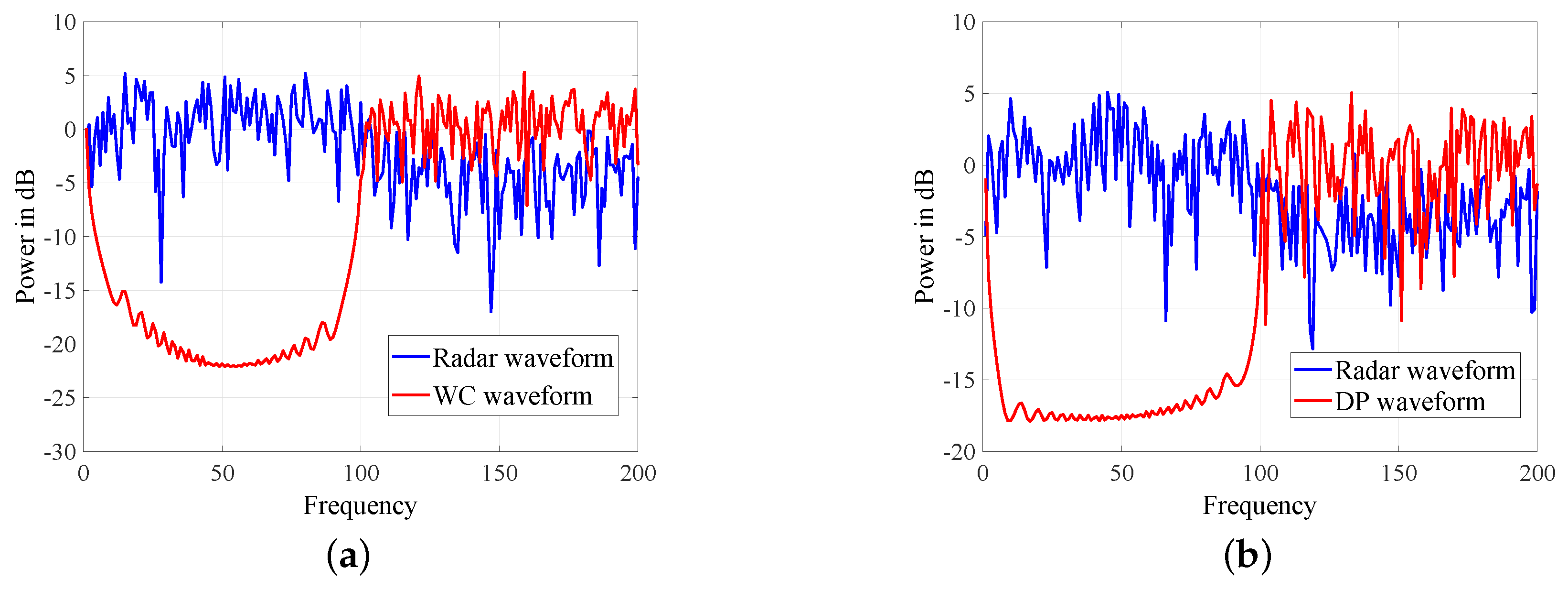
- WC strategyAs a trade-off, WC strategy weights each column vector in as follows [8]:where is a different weight vector determined by RF tag and radar, .
- (iii)
- DP strategyDP strategy considers the non-dominant region as a whole and uses projection matrices to generate REC waveforms:where is the projection matrix, which is given by [8]. is a random column vector known only to RF tag and radar.
3.2. Receiver Designs
The embedded REC waveforms have similar characteristics to the radar waveform, which makes it difficult for the eavesdropper to intercept, but it also brings a challenge for the cooperative receiver. Consequently, to ensure good communication performance (e.g., communication reliability), the reasonable design of the receiver means a lot.
The existing REC receivers include the matched filter (MF) receiver [8], the decorrelating-filter (DF) receiver [8], and the diagonally loaded decorrelating (DLD) receiver [17]. The DLD receiver has been proved to be better than the other two receivers [22], so this paper only introduces the DLD receiver.
DLD receiver constructs the decorrelating-filter as follows [22]:
where is the largest eigenvalue in the non-dominant region, is the result after decorrelating-filtering.
The decision processing are as follows [22]:
where is the index of the REC waveform, is the signal received by radar.
3.3. Performance Metrics
There are two main performance metrics of the REC system: reliability metric based on symbol error ratio (SER) and LPI metric based on normalized correlation.
- (i)
- Reliability metricIn order to analyze communication reliability, we make comparisons for the SER of REC waveforms with different signal-to-interference ratio (SIR) and signal-to-noise ratio (SNR). SIR and SNR are defined as follows.
- SIR: the ratio of the REC signal power to the interference (in REC systems, radar echoes are considered as interference.) power.
- SNR: the ratio of the REC signal power to the environmental noise power.
- (ii)
- LPI metricThe intercepted signal can be processed as follows [13]:where is the predicted projection matrix, which is given by [13]. is the intercepted signal, and is the result.
Then normalized correlation can be calculated as follows [13]:
where represents the normalized correlation. The smaller () is, the better the LPI performance would be.
3.4. Analysis of Traditional Strategies
Before the analysis, we normalize the energy of the EAW, WC and DP waveforms as follows:
where , and represent the EAW, WC and DP waveforms generated according to the above strategies, respectively.
3.4.1. Orthogonality Analysis of WC
We take two different WC waveforms and into consideration. According to Equation (9), and can be expressed as follows:
and
where and are different WC waveforms, and are different weight vectors, are the elements in , while are the elements in . x and y satisfy and while .
According to the properties of the unitary matrix, we can know as follows:
and
where , , and .
In other words, the orthogonality of WC depends on the weight vectors. However, no one has noticed this conclusion, and the weight vectors are randomly selected. Therefore, the conventional WC waveforms are not orthogonal. In the next section, we add the constraint that weight vectors are orthogonal to each other and propose CWC strategy as a method to design orthogonal REC waveforms.
3.4.2. Orthogonality Analysis of DP
The orthogonality of DP has been discussed in [19,20]. Although DP references the idea of Schmidt orthogonalization [31], DP waveforms are not completely orthogonal. In order to ensure weak correlation among different DP waveforms, the following constraint is added to DP [20]:
However, DP waveforms with this constraint are orthogonal only when the dominant region is sharply attenuated and the non-dominant eigenvalues are ideally equal. Neither of the two requirements can be achieved in engineering. Therefore, we need to find better methods to make the DP waveforms orthogonal.
4. Orthogonal Waveform Design and Performance Comparison
In this section, we propose improved strategies for WC and DP. Moreover, we compare the improved strategies with the traditional ones according to the reliability and LPI metrics mentioned above.
In order to facilitate the performance comparison below, we summarize the existing conclusions on REC waveforms as follows.
- 1.
- EAW tends to result in the lowest SER, but it is not covert. Therefore, we generally use WC and DP to construct REC waveforms. The performance of WC and DP are similar to each other.
- 2.
- Since eigen-decomposition is needed only once, WC has less computational intensity than DP. As a result, we can use WC to get lower response delay.
- 3.
- DP considers the dominant region and the non-dominant region as a whole, which solves the problem that the RF tag does not match the cooperative receiver (e.g., the matrix ).
4.1. OWC Strategy
On the basis of the WC strategy, we propose an improved waveform design strategy which is called OWC strategy. As shown in Figure 5, OWC can be summarized as the following steps.
Figure 5.
Flow chart of orthogonal weighted-combining (OWC).
- Step 1:
- According to the value of K, we choose the corresponding waveform design strategy. If , we can proceed to Step 2 to Step 4 and then go to Step 8, otherwise, we should proceed to Step 5 to Step 8.
- Step 2:
- We select column vectors that satisfy the following conditions randomly in to construct generator matrices. The specific process is as follows:
- Step 2.1:
- We determine the dimension of the generator matrix (viz., the number of column vectors selected from ). We define the number of column vectors as j (if , similar to EAW waveforms, the generated waveforms will exhibit peaks in the spectrum. Then the risk of exposure will increase). The satisfies and .
- Step 2.2:
- We select the column vectors according to the following conditions, and each waveform requires a corresponding generator matrix, denoted as ( and ). The conditions are:
- (1)
- In order to ensure orthogonality, each column vector can only be selected once. The same column vector cannot be used for two generator matrices.
- (2)
- In order to improve performance, every should select non-dominant eigenvectors corresponding to the larger eigenvalues as many as possible.
- Step 3:
- We generate a series of column vectors randomly, denoted as ( and ).
- Step 4:
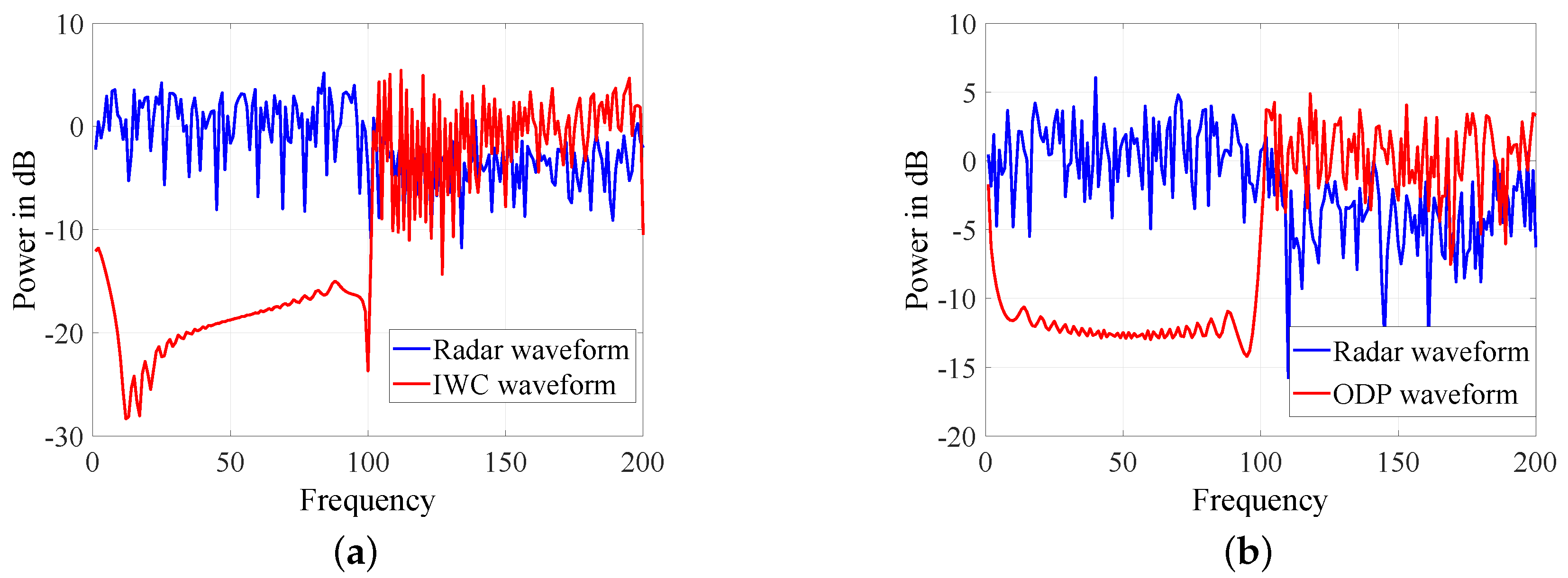
- We use and to generate REC waveforms, which are called IWC waveforms. Then, we can go to Step 8.
- Step 5:
- The RF tag and radar generate mutually orthogonal column vectors to form a vector library which is known only to themselves. Different N and are considered in the library.
- Step 6:
- We select the column vectors from the vector library randomly, denoted as ( and ).
- Step 7:
- We use and to generate REC waveforms, which are called CWC waveforms.
- Step 8:
- To further improve the LPI performance, we regularly replace the column vectors that generate the waveforms. The specific process is as follows:
If IWC waveforms are generated, after an interval, steps 3 and 4 should be repeated. If we generate CWC waveforms, after an interval, steps 6 and 7 should be repeated. This interval is determined by RF tag and radar.
To better understand the OWC strategy, we provide an example. Assuming , , , , we can get and . Since , which does not exceed the upper construction limit of IWC, we take the IWC waveforms as a priority. Therefore, we go to step 2 to step 4 and take that satisfies the requirements in Step 2.1. Then, the generator matrices are as follows:
The generated IWC waveforms are as follows:
We prioritize generating IWC waveforms for the reason that IWC has better LPI performance. However, IWC has a construction limit and cannot satisfy the case where . To solve this problem, we propose CWC as an alternative. In this way, the complete OWC strategy can be formed. Moreover, since the eigen-decomposition is likewise required only once, OWC retains the advantage of WC (viz., low response delay). More detailed theoretical explanations will be shown below.
4.2. ODP Strategy
Inspired by the OWC strategy, we also propose an improved strategy for DP, which is called ODP strategy. Traditional DP strategy brings large amount of calculation, and its response delay is high. This may result in a problem: the REC waveforms can not be embedded into the radar echo on time. Once the REC waveforms are not masked in the radar echo, the risk of exposure would increase. Therefore, in the REC system, it is important to ensure low response delay.
In fact, we can make the waveforms orthogonal by mutually orthogonal column vectors, and thus multiple eigen-decompositions are not necessary. We consider the first projection matrix in Equation (10), which is given by [22]:
where is the first projection matrix.
Then ODP waveforms can be generated as follows:
where is the mutually orthogonal column vector known only to RF tag and radar.
In this way, we can not only ensure the orthogonality of the ODP waveforms, but also retain the advantage of DP (viz., robustness).
4.3. Comparison of Communication Reliability
Similar to Equation (15), we normalize the energy of the CWC, IWC and ODP waveforms as follows:
where , and represent the CWC, IWC and ODP waveforms generated according to the above strategies, respectively.
4.3.1. Reliability Analysis of CWC and IWC
Due to the properties of the unitary matrix, similar to Equations (16)–(20), we can get the following conclusion:
where and are different CWC waveforms, and are different column vectors. Obviously, the CWC waveforms are orthogonal.
According to the first condition in Step 2.2, we can use Equations (18) and (19) to prove . Further conclusions are as follows:
where and are different IWC waveforms, and are different column vectors. In other words, the IWC waveforms are orthogonal.
From Equations (29) and (30), we can see that the OWC strategy makes the orthogonal REC waveforms come true. Therefore, CWC and IWC have better communication reliability than WC. In addition, for IWC waveforms, the coefficient in Equation (11) is not optimal due to changes in the construction. As a result, the communication reliability of IWC cannot be optimized by the DLD receiver. CWC would have better communication reliability than IWC.
4.3.2. Reliability Analysis of ODP
Due to the properties of Hermitian, we can prove the following conclusion [18]:
According to Equations (18) and (19), we can prove the idempotent property of the projection matrix [18]:
Combining Equations (27), (31) and (32), we can derive as follows:
where and are different ODP waveforms, and are different column vectors.
Since and are mutually orthogonal, we can know . Substituting Equation (26) into Equation (33), we can further derive as follows:
Due to the properties of the dominant region, we can know . We can get the conclusion as follows:
Moreover, according to Equations (31) and (32), we can prove that ODP waveforms satisfy the constraint in Equation (21). ODP waveforms achieve the requirement that non-dominant eigenvectors are equal. Therefore, the orthogonality of ODP is stronger than that of DP. We can approximate that the ODP waveforms are orthogonal.
In other words, ODP has better communication reliability than DP. ODP needs only one eigen-decomposition, so it would have less computational complexity than DP.
4.4. Comparison of LPI Performance
The predicted projection matrix is given by [19]:
where l is the predicted size of the dominant region, is the predicted projection matrix, and consists of predicted non-dominant eigenvectors. l satisfies and .
We use the metric mentioned above to measure the LPI performance. As it is proved in [19], the value of determines the normalized correlation . The larger the value of , the larger the value of will be. For convenience, we define . We define the value of R corresponding to WC, CWC, IWC, DP and ODP as , , , and , respectively. In addition, we assume that the elements in each column vector (viz., , , , and ) are identically distributed.
4.4.1. LPI Performance Analysis of CWC and IWC
can be calculated as follows:
According to Equation (9), can be expressed as follows:
where are the elements in the column vector . and .
From Equation (15), we can know . From Equation (20), we can know . Therefore, we can derive as follows:
Compared with WC, CWC only adds some constraints. Therefore, the derivation of is the same as . can be expressed the same as Equation (41).
can be calculated as follows. Firstly, according to Equation (22), can be expressed as follows:
where are the elements in the column vector , are column vectors in .
Similar to Equation (20), we can derive . From Equation (28), we can know . Then further conclusion can be obtained as follows:
would change if we select different generator matrices. By adjusting the generator matrix, we can make the value of much smaller than that of . In order to compare the LPI performance intuitively, we consider the typical IWC waveform similar to in Equation (25). Obviously, possesses an expression similar to Equation (38). Combining Equations (18), (19), (42) and (43), we can derive as follows:
Since the elements in are identically distributed, we can derive as follows:
If we take the expectation at both sides of Equation (40), we can write
Due to the properties of expectation, Equation (46) can be rewritten as
According to Equation (48), if we take the expectation at both sides of Equation (41), we can derive as follows:
Similarly, can be calculated as
Generally, , and it is easy to prove
In other words, IWC can achieve better LPI performance than WC, and the LPI performance of CWC is the same as that of WC. Moreover, IWC adds more variables (viz., the number of column vectors and different combinations of column vectors), and thus it is more difficult to intercept without prior knowledge.
4.4.2. LPI Performance Analysis of ODP
Similar to Equation (38), can be expressed as follows:
Note that different DP waveforms correspond with different non-dominant eigenvectors [8], cannot be expressed accurately. To compare the LPI performance intuitively, we assume that the non-dominant eigenvalues are equal. According to Equation (10), can be expressed as follows:
Similar to Equation (56), we can prove
From Equations (55), (56), (58) and (59), we can see and have similar expression and constraint. Furthermore, we define L in Equations (55) and (56) as , and L in Equations (58) and (59) as . If , and will have the same expression and constraint, and their LPI performance will be the same.
Actually, K always satisfies . From the definition of t, we know . As a result, we can know . When , we can derive . In addition, the slight change of the dominant region would not affect the performance a lot. Therefore, we can derive that the LPI performance of ODP and DP are similar to each other.
5. Simulation Results
In this section, we make several simulations to demonstrate the performance of our strategies. We assume that the radar transmits a length N nominally-sampled LFM waveform which is oversampled by an oversampling factor . The LFM waveform is modeled by the mathematical function for the P3 code [13], and its sampled version is . The clutter and environmental noise are modeled as white Gaussian. We assume that the elements in each column vector (viz., , , , and ) are identically distributed. The parameters are: , , , .
In Figure 6, Figure 7 and Figure 8, we check the spectrums of five strategies. As shown in Figure 6, EAW has explicit peaks in the spectrum, and thus it is not covert. As a result, we will no longer consider it in other simulations. WC, DP, CWC, IWC and ODP do not have obvious peaks and are similar to the radar waveform in the stopband. CWC is a special case of WC, and the spectrum of CWC is similar to that of WC as Figure 7a. Besides, as shown in Figure 7b and Figure 8b, the spectrums of DP and ODP are similar. Since only a part of non-dominant eigenvectors are selected, the difference between IWC and radar waveform is greater than that of ODP and radar waveform. However, we can see from Figure 8a that IWC is still under the mask of radar waveform. These simulations have shown that WC, DP, CWC, IWC and ODP all possess the LPD performance.
Figure 6.
Spectrum of eigenvectors-as-waveforms (EAW). (a) Eigenvector corresponding to smaller eigenvalue. (b) Eigenvector corresponding to larger eigenvalue.
Figure 7.
Spectrum of weighted-combining (WC) and dominant-projection (DP). (a) Spectrum of WC (b) Spectrum of DP.
Figure 8.
Spectrum of improved weighted-combining (IWC) and ODP. (a) Spectrum of IWC (b) Spectrum of orthogonal dominant-projection (ODP).
Figure 9 shows the reliability comparison between the traditional strategies and the proposed. We consider the typical IWC waveforms mentioned in Equations (24) and (25) as an example. A DLD receiver is used, and the SIR is set to −25 dB and −30 dB. When SIR is −25 dB, CWC outperforms WC with 3.5 dB at SER of while IWC outperforms WC with 1.5dB. This trend is more pronounced when SIR is decreased. In the SIR of −30 dB, CWC outperforms WC with 16 dB at SER of while IWC outperforms WC with 10 dB. ODP also remarkably improves reliability on the basis of DP. At SIR −25 dB, ODP outperforms DP with 1.5 dB at SER of . In the SIR of −30 dB, ODP outperforms DP with 6 dB at SER of .
Figure 9.
Comparison of communication reliability. (a) Signal-to-interference ratio (SIR) = −25 dB (b) SIR = −30 dB.
These gains are attributed to the orthogonal waveform designs. The ODP waveforms are approximately orthogonal, and thus the reliability of ODP is worse than that of CWC and IWC. In addition, the DLD receiver is not optimal for IWC, so the reliability of IWC is worse than that of CWC. These simulations have shown that CWC, IWC and ODP strongly improve the communication reliability.
The comparison of LPI performance is shown in Figure 10. The IWC waveforms are the same as the above, and SNR is set to −5 dB. We make comparisons between these five strategies when the SIR is −25 dB and −35 dB. By comparing the envelope area, we can come to conclusions as follows. IWC has the smallest envelope area, and thus its LPI performance is the best. Since the envelope area of CWC and WC are similar, CWC does not decrease LPI performance when comparing to WC. Similarly, compared with DP, ODP does not decrease its LPI performance.
Figure 10.
Comparison of the low probability of intercept (LPI) performance. (a) SIR = −25 dB, signal-to-noise ratio (SNR) = −5 dB (b) SIR = −35 dB, SNR = −5 dB.
6. Conclusions
This paper elaborates on the idea of REC and analyzes the traditional waveform design strategies. In order to solve the problem that the conventional REC waveforms are not orthogonal, the OWC and ODP strategies are proposed. The OWC strategy can be divided into two parts: CWC strategy and IWC strategy. Theoretical analysis and simulation results have shown that the proposed strategies have advantages of communication reliability and LPI performance. Specifically, the CWC strategy has the best communication reliability while the LPI performance is unchanged. The IWC strategy has the best LPI performance while the reliability is increased. The ODP strategy increases reliability while the computational complexity is reduced. In conclusion, if the application scenario requires high communication reliability, we can choose the CWC strategy. If the application scenario requires high communication covertness, we can choose the IWC strategy. In addition, if the RF tag and the cooperative receiver do not match with each other in the application scenario, the ODP strategy can be considered.
We will focus on the duplex design and networking application in future research. Additionally, the synchronization problem and the establishment of a multi-user REC link need to be considered as well.
Author Contributions
This work was conceived and designed by J.X., B.L., Z.H.; experiments were performed by J.X., B.L., Z.H.; results were analyzed by all authors. All authors were involved in paper writing.
Funding
This work was supported in part by the National Natural Science Foundation of China under Grant 61502518, and the Natural Science Foundation of Hunan Province under Grant 2018JJ3609, and the Program for Innovative Research Groups of Hunan Provincial Natural Science Foundation of China under Grant 2019JJ10004.
Conflicts of Interest
The authors declare no conflict of interest.
Abbreviations
The following abbreviations are used in this manuscript:
| DARPA | Defense Advanced Research Projects Agency |
| SSPARC | Shared Spectrum Access for Radar and Communications |
| REC | Radar-embedded communication |
| RF | Radio frequency |
| LPD | Low probability of detection |
| LPI | Low probability of intercept |
| AFOSR | Air Force Office of Scientific Research |
| ONR | Office of Naval Research |
| CPM | Continuous phase modulation |
| DP | Dominant-projection |
| WC | Weighted-combining |
| IWC | Improved weighted-combining |
| CWC | Constrained weighted-combining |
| OWC | Orthogonal weighted-combining |
| ODP | Orthogonal dominant-projection |
| LFM | Linear frequency modulated |
| AWGN | Additive white Gaussian noise |
| EAW | Eigenvectors-as-waveforms |
| MF | Matched filter |
| DF | Decorrelating-filter |
| DLD | Diagonally loaded decorrelating |
| SER | Symbol error ratio |
| SIR | Signal-to-interference ratio |
| SNR | Signal-to-noise ratio |
References
- Jacyna, G.M.; Fell, B.; McLemore, D. A High-Level Overview of Fundamental Limits Studies for the DARPA SSPARC Program. In Proceedings of the 2016 IEEE Radar Conference (RadarConf), Philadelphia, PA, USA, 2–6 May 2016; pp. 1–6. [Google Scholar]
- Zhang, W.; Wang, C.; Ge, X.; Chen, Y. Enhanced 5G Cognitive Radio Networks Based on Spectrum Sharing and Spectrum Aggregation. IEEE Trans. Commun. 2018, 66, 6304–6316. [Google Scholar] [CrossRef]
- Roessler, A. Impact of Spectrum Sharing on 4G and 5G Standards a Review of How Coexistance and Spectrum Sharing is Shaping 3GPP Standards. In Proceedings of the 2017 IEEE International Symposium on Electromagnetic Compatibility Signal/Power Integrity (EMCSI), Washington, DC, USA, 7–11 August 2017; pp. 704–707. [Google Scholar]
- Sorayya, R.; Suryanegara, M. The Model of Spectrum Sharing Between a Primary and Two Secondary Operators. In Proceedings of the 2017 International Conference On Smart Technologies For Smart Nation (SmartTechCon), Bangalore, India, 17–19 August 2017; pp. 518–522. [Google Scholar]
- Griffiths, H.; Cohen, L.; Watts, S.; Mokole, E.; Baker, C.; Wicks, M.; Blunt, S. Radar Spectrum Engineering and Management: Technical and Regulatory Issues. Proc. IEEE 2015, 103, 85–102. [Google Scholar] [CrossRef]
- Metcalf, J.G.; Sahin, C.; Blunt, S.D.; Rangaswamy, M. Analysis of Symbol-Design Strategies for Intrapulse Radar-Embedded Communications. IEEE Trans. Aerosp. Electron. Syst. 2015, 51, 2914–2931. [Google Scholar] [CrossRef]
- Blunt, S.D.; Stiles, J.; Allen, C.; Deavours, D.; Perrins, E. Diversity Aspects of Radar-Embedded Communications. In Proceedings of the 2007 International Conference on Electromagnetics in Advanced Applications, Torino, Italy, 17–21 September 2007; pp. 439–442. [Google Scholar]
- Blunt, S.D.; Yantham, P. Waveform Design for Radar-Embedded Communications. In Proceedings of the 2007 International Waveform Diversity and Design Conference, Pisa, Italy, 4–8 June 2007; pp. 214–218. [Google Scholar]
- Ben Kilani, M.; Gagnon, G.; Gagnon, F. Multistatic Radar Placement Optimization for Cooperative Radar-Communication Systems. IEEE Commun. Lett. 2018, 22, 1576–1579. [Google Scholar] [CrossRef]
- Chen, B.; Zhu, C.; Li, W.; Wei, J.; Leung, V.C.M.; Yang, L.T. Original Symbol Phase Rotated Secure Transmission Against Powerful Massive MIMO Eavesdropper. IEEE Access 2016, 4, 3016–3025. [Google Scholar] [CrossRef]
- Li, W.; McLernon, D.; Lei, J.; Ghogho, M.; Zaidi, S.A.R.; Hui, H. Cryptographic Primitives and Design Frameworks of Physical Layer Encryption for Wireless Communications. IEEE Access 2019, 7, 63660–63673. [Google Scholar] [CrossRef]
- Li, W.; McLernon, D.; Lei, J.; Ghogho, M.; Zaidi, S.A.R.; Hui, H. Mathematical Model and Framework of Physical Layer Encryption for Wireless Communications. In Proceedings of the 2018 IEEE Globecom Workshops (GC Wkshps), Abu Dhabi, UAE, 9–13 December 2018; pp. 1–7. [Google Scholar]
- Blunt, S.D.; Yatham, P.; Stiles, J. Intrapulse Radar-Embedded Communications. IEEE Trans. Aerosp. Electron. Syst. 2010, 46, 1185–1200. [Google Scholar] [CrossRef]
- Blunt, S.D.; Biggs, C.R. Practical Considerations for Intra-Pulse Radar-Embedded Communications. In Proceedings of the 2009 International Waveform Diversity and Design Conference, Kissimmee, FL, USA, 8–13 February 2009; pp. 244–248. [Google Scholar]
- Blunt, S.D.; Metcalf, J.G. Estimating Temporal Multipath via Spatial Selectivity: Building Environmental Knowledge into Waveform Design for Radar-Embedded Communications. In Proceedings of the 2009 International Conference on Electromagnetics in Advanced Applications, Torino, Italy, 14–18 September 2009; pp. 513–516. [Google Scholar]
- Blunt, S.D.; Metcalf, J.G. Using Time Reversal of Multipath for Intra-Pulse Radar-Embedded Communications. In Proceedings of the 2010 International Waveform Diversity and Design Conference, Niagara Falls, ON, Canada, 8–13 August 2010; pp. 155–158. [Google Scholar]
- Metcalf, J.G.; Blunt, S.D.; Perrins, E. Detector Design and Intercept Metrics for Intra-Pulse Radar-Embedded Communications. In Proceedings of the 2011 IEEE Military Communication Conference (MILCOM), Baltimore, MD, USA, 7–10 November 2011; pp. 188–192. [Google Scholar]
- Blunt, S.D.; Metcalf, J.G.; Biggs, C.R.; Perrins, E. Performance Characteristics and Metrics for Intra-Pulse Radar-Embedded Communication. IEEE J. Sel. Areas Commun. 2011, 29, 2057–2066. [Google Scholar] [CrossRef]
- Ciuonzo, D.; De Maio, A.; Foglia, G.; Piezzo, M. Pareto-Theory for Enabling Covert Intrapulse Radar-Embedded Communications. In Proceedings of the 2015 IEEE Radar Conference (RadarConf), Arlington, VA, USA, 10–15 May 2015; pp. 292–297. [Google Scholar]
- Ciuonzo, D.; De Maio, A.; Foglia, G.; Piezzo, M. Intrapulse Radar-Embedded Communications via Multiobjective Optimization. IEEE Trans. Aerosp. Electron. Syst. 2015, 51, 2960–2974. [Google Scholar] [CrossRef]
- Mai, C.; Sun, J.; Zhou, R.; Wang, G. Sparse Frequency Waveform Design for Radar-Embedded Communication. Math. Probl. Eng. 2016, 2016, 1–7. [Google Scholar] [CrossRef]
- Li, B.; Lei, J.; Cao, W.; Wen, L.; Mou, Y. Waveform Design for Radar-Embedded Communications Exploiting Spread Spectrum Technology. IET Commun. 2016, 10, 1631–1639. [Google Scholar] [CrossRef]
- He, S.; Li, B.; Lei, J.; Yan, H. A New Shaped Waveform Design Scheme for Radar Embedded Communication. In Proceedings of the 2018 International Conference on Smart Materials, Intelligent Manufacturing and Automation (SMIMA), Nanjing, China, 24–26 May 2018. [Google Scholar]
- Sahin, C.; Metcalf, J.G.; Blunt, S.D. Filter Design to Address Range Sidelobe Modulation in Transmit-Encoded Radar-Embedded Communications. In Proceedings of the 2017 IEEE Radar Conference (RadarConf), Seattle, WA, USA, 8–12 May 2017; pp. 1509–1514. [Google Scholar]
- Sahin, C.; Metcalf, J.G.; Blunt, S.D. Characterization of Range Sidelobe Modulation Arising from Radar-Embedded Communications. In Proceedings of the 2017 International Conference on Radar Systems (Radar 2017), Belfast, UK, 23–26 October 2017; pp. 1–6. [Google Scholar]
- Sahin, C.; Metcalf, J.G.; Himed, B. Reduced Complexity Maximum SINR Receiver Processing for Transmit-Encoded Radar-Embedded Communications. In Proceedings of the 2018 IEEE Radar Conference (RadarConf), Oklahoma City, OK, USA, 23–27 April 2018; pp. 1317–1322. [Google Scholar]
- Geng, Z.; Xu, R.; Deng, H.; Himed, B. Fusion of Radar Sensing and Wireless Communications by Embedding Communication Signals into the Radar Transmit Waveform. IET Radar Sonar Navig. 2018, 12, 632–640. [Google Scholar] [CrossRef]
- Xu, J.; Li, B.; Huang, Z.; Lei, J. Waveform Design for Radar-Embedded Communications Based on Weighted-Combining. In Proceedings of the 2019 2nd International Conference on Mechanical Engineering, Industrial Materials and Industrial Electronics (MEIMIE), Dalian, China, 29–30 March 2019; pp. 380–387. [Google Scholar]
- Wu, Q.; Zhao, F.; Wang, J.; Liu, X.; Xiao, S. Improved ISRJ-Based Radar Target Echo Cancellation Using Frequency Shifting Modulation. Electronics 2019, 8, 46. [Google Scholar] [CrossRef]
- Sodagari, S.; Khawar, A.; Clancy, T.C.; McGwier, R. A Projection Based Approach for Radar and Telecommunication Systems Coexistence. In Proceedings of the 2012 IEEE Global Communications Conference (GLOBECOM), Anaheim, CA, USA, 3–7 December 2012; pp. 5010–5014. [Google Scholar]
- Hu, X.; Song, Y.; Sun, Y.; Yang, X. Derivative Constrained Gram-Schmidt Orthogonalization Beamforming Method with Widened Nulls. In Proceedings of the 2015 IET International Radar Conference, Hangzhou, China, 14–16 October 2015; pp. 1–5. [Google Scholar]
© 2019 by the authors. Licensee MDPI, Basel, Switzerland. This article is an open access article distributed under the terms and conditions of the Creative Commons Attribution (CC BY) license (http://creativecommons.org/licenses/by/4.0/).