Method of Estimating Human Orientation Using Array Antenna

Abstract
:1. Introduction
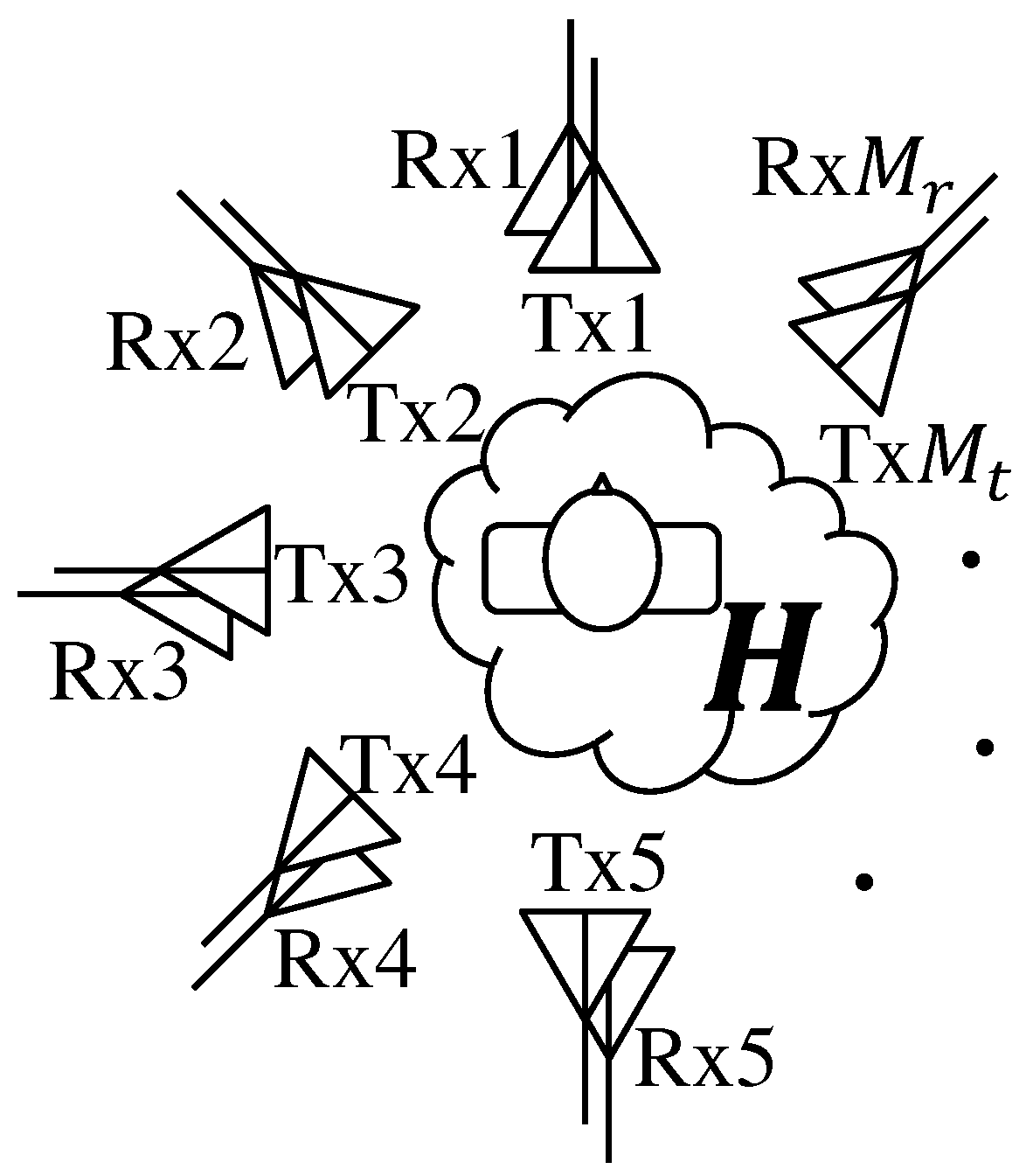
2. Method of Estimating Body Orientation Using Array Antenna
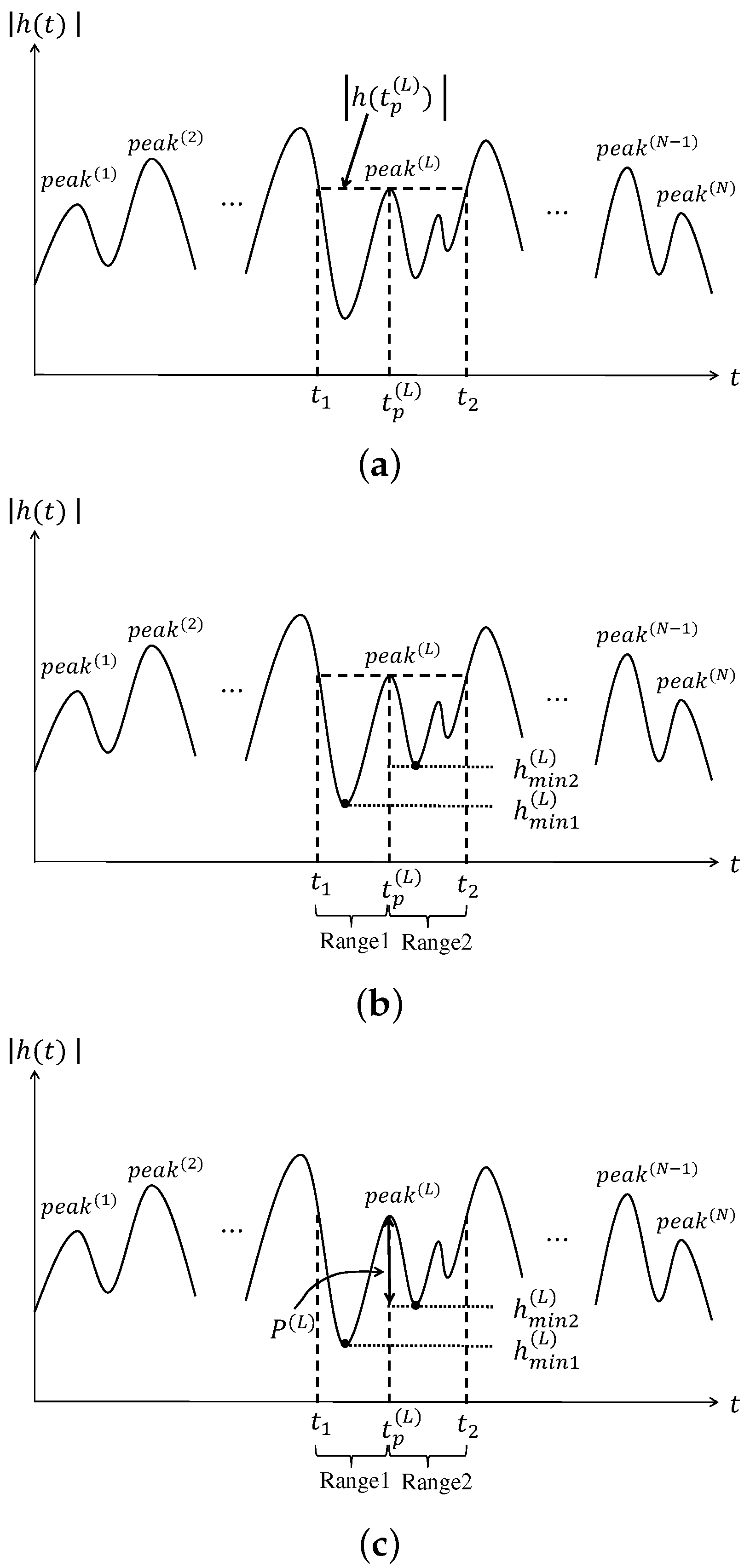
- Step 1:
- When absolute value the channel has N peaks, the time of the Lth peak is . We draw a line horizontally from until it hits a higher peak to the left and right; let and be the times at which the line intersects the left and right peaks, respectively. When there is no higher peak, , are taken to be the ends of the signal.
- Step 2:
- When the minimum values between and and between and are and ,
- Step 3:
- If is the larger of and , the prominence at is expressed asis called prominence. The total value of the prominence of the channel from transmitting antenna j to receiving antenna i is expressed asThe sum of the prominences of all receiving antennas generated by transmitting antenna j is expressed as
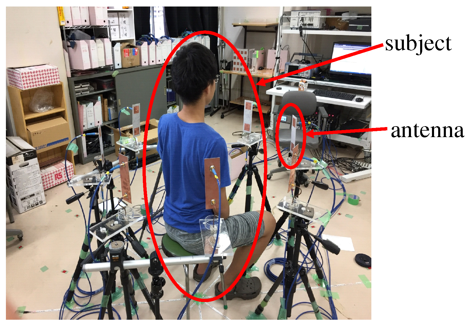
3. Experiment
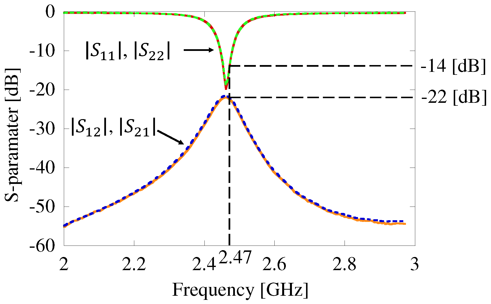
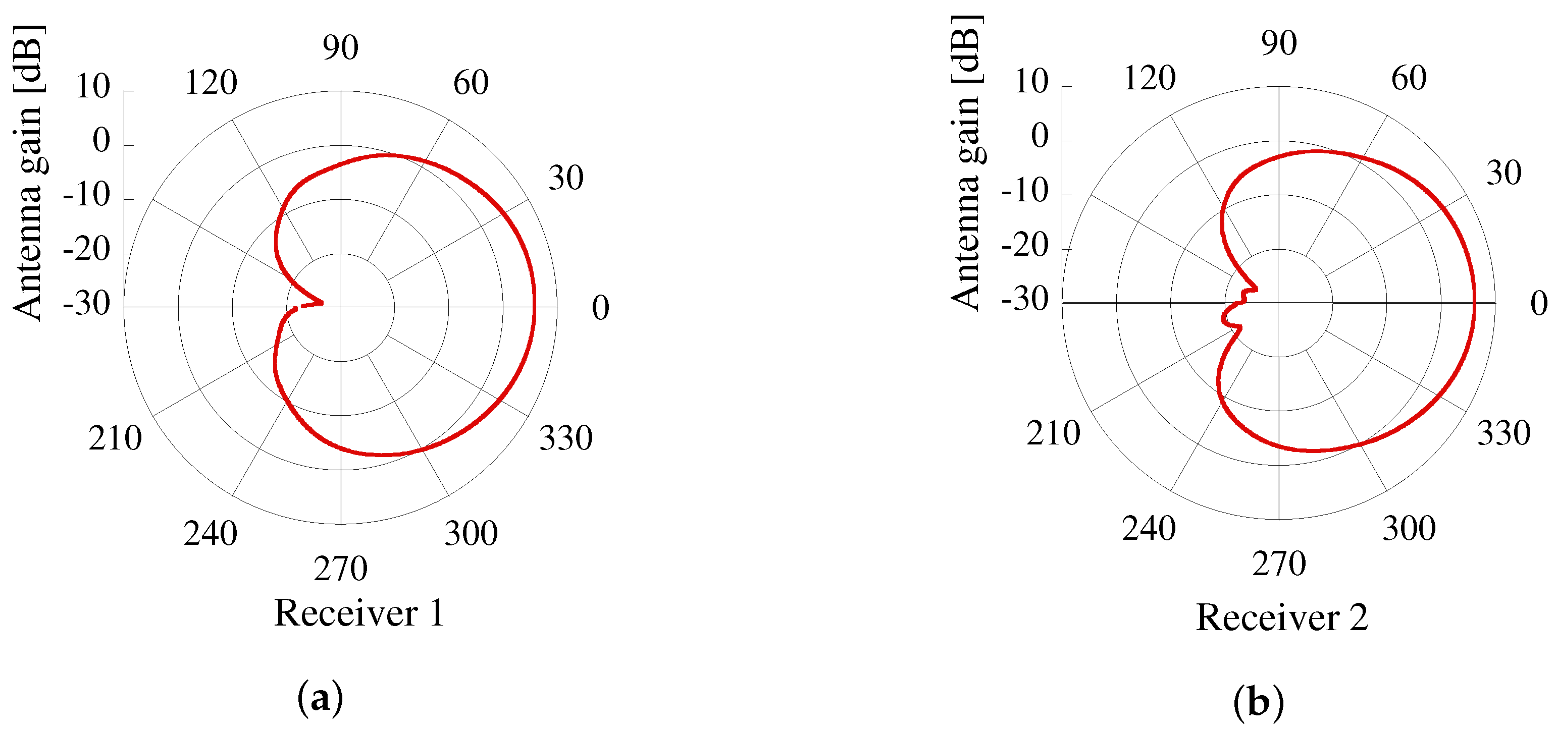
3.1. Calibration
3.2. Measurement Conditions
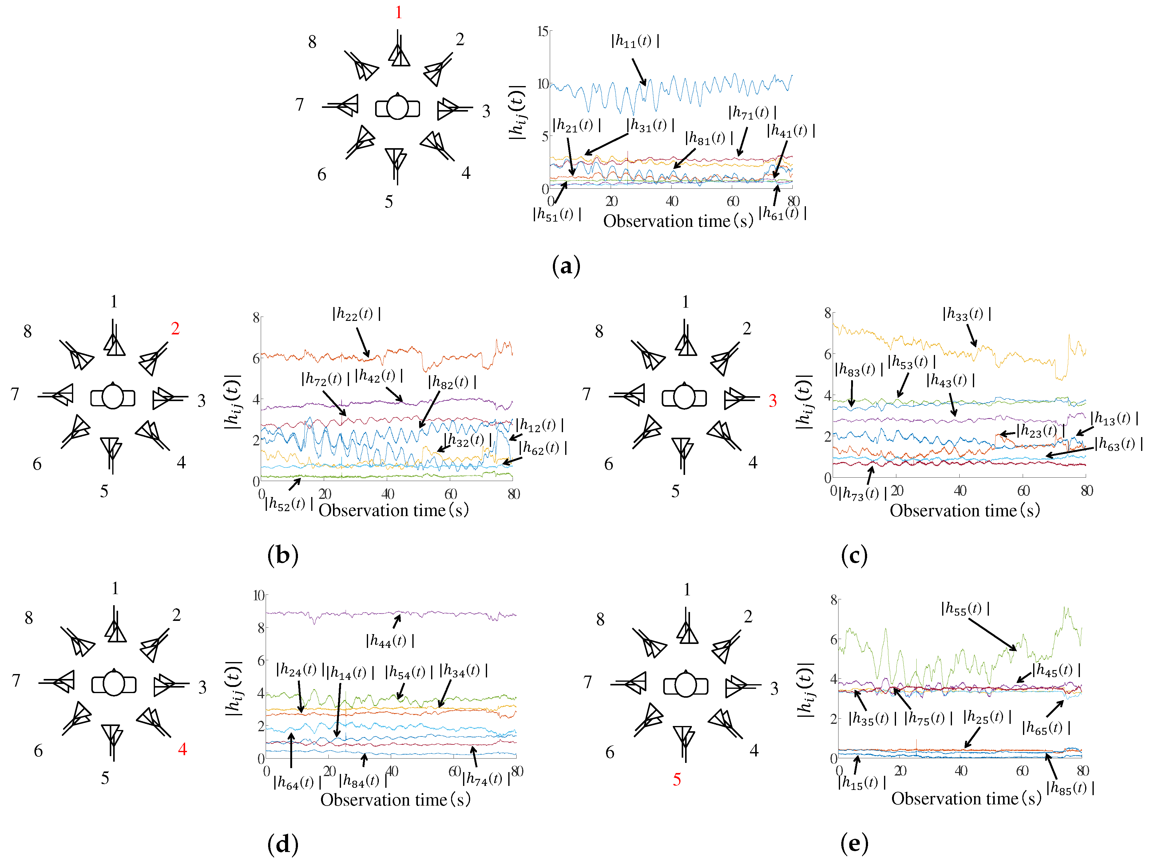
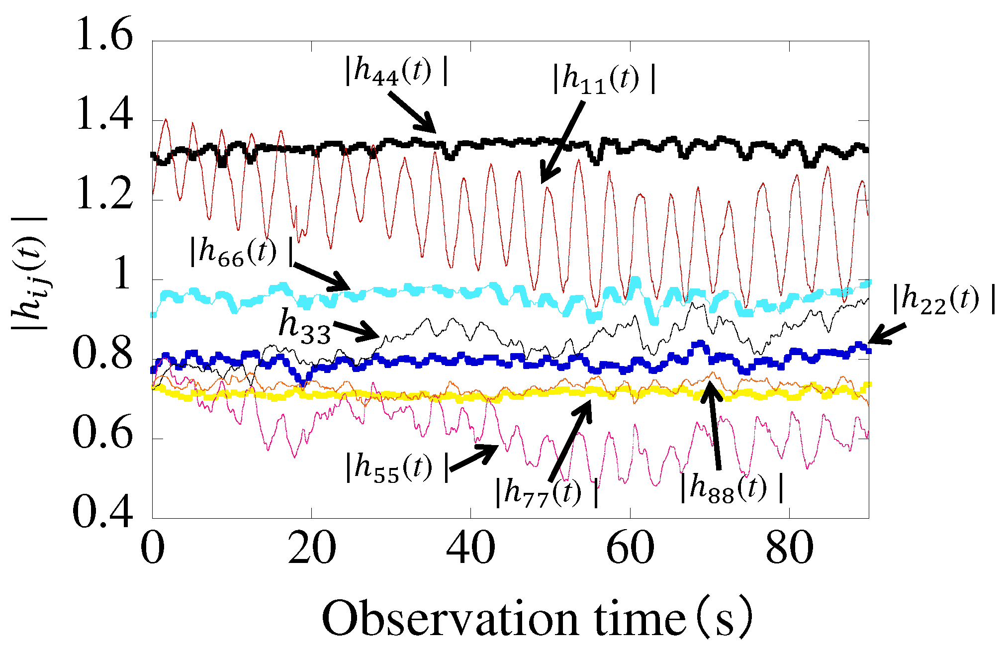
3.3. Measured Results
4. Conclusions
Author Contributions
Conflicts of Interest
Abbreviations
| MIMO | Multiple-Input Multiple-Output |
| CDF | Cumulative Distribution Function |
| DOA | Direction Of Arrival |
| DOD | Direction Of Departure |
References
- Fiore, L.; Fehr, D.; Bodor, R.; Drenner, A.; Somasundaram, G.; Papanikolopoulos, N. Multi-camera human 240 activity monitoring. Intell. Robot. Sys. 2008, 52, 5–43. [Google Scholar] [CrossRef]
- Norbert, N.; Thierry, H.; Vincent, R.; Gilles Eric, M.; Gilles, M.; Aldo, M.; Thieny, P.; Porcheron, T. Monitoring behavior in home using a smart fall sensor and position sensors. In Proceedings of the 1st Annual International, Conference, Microtechnologies in Medicine and Biology, Lyon, France, 12–14 October 2000; pp. 607–610. [Google Scholar] [CrossRef]
- Lin, J.C. Noninvasive microwave measurement of respiration. Proc. IEEE 1975, 63, 1530. [Google Scholar] [CrossRef]
- Droitcour, A.; Lubecke, V.; Lin, J.; Boric-Lubecke, O. A microwave radio for Doppler radar sensing of vital signs. In Proceedings of the 2001 IEEE MTT-S International, Microwave Symposium Digest, Phoenix, AZ, USA, 20–24 May 2001; pp. 175–178. [Google Scholar] [CrossRef]
- Avagyan, H.; Hakhoumian, A.; Hayrapetyan, H.; Pogosyan, N.; Zakaryan, T. Portable non-contact microwave Doppler radar for respiration and heartbeat sensing. Am. J. Phys. 2012, 5, 8–14. [Google Scholar]
- Adib, F.; Kabelac, Z.; Katabi, D.; Miller, R.C. 3D Tracking via Body Radio Reflections. In Proceedings of the 11th USENIX Conference on Networked Systems Design and Implementation (NSDI’14), Seattle, WA, USA, 2–4 April 2014; pp. 317–329. [Google Scholar]
- Li, J.; Stoica, P. MIMO Radar Signal Processing; John Wiley & Sons, Inc.: Hoboken, NJ, USA, 2009; ISBN 978-0470178980. [Google Scholar]
- Konno, K.; Honma, N.; Sasakawa, D.; Tsunekawa, Y.; Nishimori, K.; Takemura, N.; Mitsui, T. Localizing multiple target using bistatic MIMO radar in multi-path environment. In Proceedings of the 2014 IEEE International Workshop on Electromagnetics (iWEM), Sapporo, Japan, 4–6 August 2014; pp. 90–91. [Google Scholar] [CrossRef]
- Konno, K.; Honma, N.; Sasakawa, D.; Nishimori, K.; Takemura, N.; Mitsui, T.; Tsunekawa, Y. Estimating living-body location using bistatic MIMO radar in multi-path environment. IEICE Trans. Commun. 2015, 98, 2314–2321. [Google Scholar] [CrossRef]
- Konno, K.; Nango, M.; Honma, N.; Nishimori, K.; Takemura, N.; Mitsui, T. Experimental evaluation of estimating living-body direction using array antenna for multipath environment. IEEE Antennas Wirel. Propag. Lett. 2014, 13, 718–721. [Google Scholar] [CrossRef]
- Marcos, L. Building past landscape perception with GIS: Understanding topographic prominence. Archaeol. Sci. 2001, 28, 1005–1014. [Google Scholar]


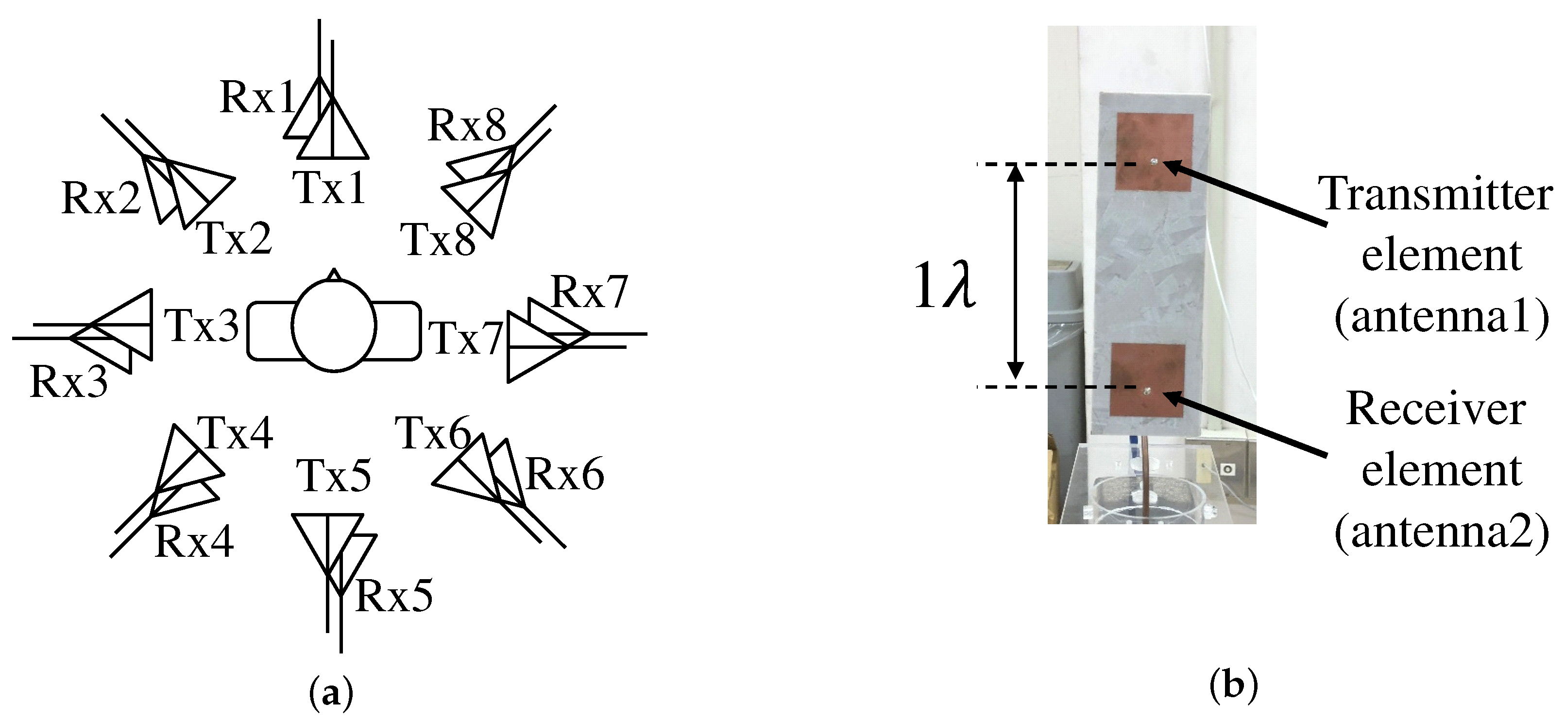
| Antenna Element | 8-Element Circular Array Antenna |
|---|---|
| Distance between Tx and Rx | 1 |
| Height of the Rx | 80 cm |
| Distance between the antenna and the subject | 50 cm |
| Frequency | 2.47125 GHz |
| Sampling frequency | 100 Hz |
| Channel measurement time | 25 s |
| Human orientation | 16 directions (22.5° intervals) |
| Transmission power | 10 dBm |
© 2018 by the authors. Licensee MDPI, Basel, Switzerland. This article is an open access article distributed under the terms and conditions of the Creative Commons Attribution (CC BY) license (http://creativecommons.org/licenses/by/4.0/).
Share and Cite
Shiraki, N.; Chen, Z.; Sasakawa, D.; Honma, N.; Nakayama, T.; Iizuka, S. Method of Estimating Human Orientation Using Array Antenna. Electronics 2018, 7, 92. https://doi.org/10.3390/electronics7060092
Shiraki N, Chen Z, Sasakawa D, Honma N, Nakayama T, Iizuka S. Method of Estimating Human Orientation Using Array Antenna. Electronics. 2018; 7(6):92. https://doi.org/10.3390/electronics7060092
Chicago/Turabian StyleShiraki, Nobuyuki, Zhixiong Chen, Dai Sasakawa, Naoki Honma, Takeshi Nakayama, and Shoichi Iizuka. 2018. "Method of Estimating Human Orientation Using Array Antenna" Electronics 7, no. 6: 92. https://doi.org/10.3390/electronics7060092
APA StyleShiraki, N., Chen, Z., Sasakawa, D., Honma, N., Nakayama, T., & Iizuka, S. (2018). Method of Estimating Human Orientation Using Array Antenna. Electronics, 7(6), 92. https://doi.org/10.3390/electronics7060092