Abstract
Multiband antennas have high value within the telecommunications field, including satellite applications. Among the different solutions proposed in the scientific literature, a lack of attention is reserved for fractal antennas, which represent a very appealing and simple option to obtain a multiband behavior. In this paper, a printed monopole, resulting from the combination of the Sierpinski gasket and the Von Koch snowflake fractals, is proposed. The antenna takes advantage of the two fractal geometries to achieve multiband operation and miniaturization, both desirable features in antennas for satellite applications. The proposed fractal monopole works in S-band (2.75–3.96 GHz), C-band (6.15–7.6 GHz), and X-band (11–11.15 GHz) for satellite communication, with a realized gain of 2.8, 4.02, and 3.75 dBi; a high efficiency (up to 97%); and a compact size (0.52λ0 × 0.3λ0 × 0.006λ0 at the lowest operating frequency).
1. Introduction
With the ever-growing advancement of wireless and telecommunication technologies and the coexistence of different communication protocols, the demand for antennas capable of multiband operation is continuously increasing [1,2]. Among the various multiband configurations reported in the scientific literature, monopole antennas [3], inverted-F or inverted-L antennas (IFAs or ILAs) [4,5], and patch antennas [6] are commonly employed. Monopole antennas are particularly appreciated for their low-profile characteristics, lightweight structure, and cost-effectiveness [2]. The low-profile feature, in particular, is especially advantageous for the integration of antennas into complex telecommunication devices.
Multiband behavior in monopole antennas is commonly achieved by employing slots [7], parasitic loops [8], defected ground planes [9], or additional resonators [10]. Over the past five years, and considering single-radiator configurations, numerous research works have addressed antennas designed for multiband operation [11,12,13,14,15,16,17,18,19,20,21,22,23,24,25,26,27,28,29]. Nevertheless, there is a noticeable scarcity of solutions based on the use of fractal geometries to achieve multiple resonances. The adoption of fractal geometries to introduce additional resonances represents a simple, elegant, and effective approach. Fractal antennas experienced a peak in popularity approximately two decades ago [30]; however, since then, interest in this topic has significantly declined, as evidenced by the limited number of publications over the last 20 years [31,32,33,34].
Owing to the self-similarity of certain fractal geometries, it is possible to obtain antenna structures exhibiting multiple resonances within a confined physical space. This is the case of the Sierpinski gasket, which is generated by starting from an equilateral triangle and removing a central triangle whose vertices are located at the midpoints of the sides of the original triangle, thereby producing three smaller equilateral triangles [35,36]. The side length of the newly formed triangles is one half of that of the original triangle. This process can be iteratively repeated, with each iteration generating three times the number of triangles of the previous stage. From an antenna-design perspective, this procedure results in multiple resonant elements, each smaller than the preceding one and therefore resonating at progressively higher frequencies.
Other fractal geometries are particularly effective in increasing the electrical length of the outer perimeter of a printed antenna, thereby enabling antenna miniaturization. A simple and well-known example is the Von Koch snowflake [35]. Similar to the Sierpinski gasket, this fractal also originates from an equilateral triangle; however, its iterative process is conceptually the opposite. In this case, the fractal geometry is formed by successively adding smaller triangular sections to the original structure, centered at the midpoint of each side of the initial triangle [35].
Only a limited number of combined fractal antenna designs have been reported in the scientific literature, and even fewer merge the specific Sierpinski and Von Koch patterns [37,38]. The strength and novel aspect of the proposed design lie in its frequency response, which is achieved exclusively through the interaction between the Sierpinski and Von Koch geometries. In fact, this interaction accounts for both the multiband behavior and the miniaturization effect, relying on the simple combined fractal geometry and a thorough choice of the feeding line. Contrary to what has been presented so far in the open literature, this result has been achieved without the need for additional matching resonators or defected ground planes. This means that the proposed layout is simpler and more effective. Each fractal iteration is thoroughly documented through simulated results, and particular attention is devoted to the clear presentation of the antenna radiation characteristics. Additionally, no other work on this specific topic, in the scientific literature, has dealt with the problem of increasing cross-polarization levels tied to the number of fractal iterations, which in this paper is well-documented.
By combining the Von Koch and Sierpinski geometries, this paper presents a relatively simple, compact, and low-profile printed fractal monopole antenna capable of multiband operation. These characteristics are highly desirable in applications such as satellite communications (e.g., CubeSat constellations), where available space is severely constrained [39,40]. This work demonstrates that the hybridization of two distinct fractal geometries gives rise to emergent electromagnetic properties that cannot be achieved by either fractal alone. The obtained results indicate that the combination of self-similar and space-filling fractals enables a systematic trade-off between bandwidth and antenna miniaturization. Moreover, this design approach may be extended to other fractal geometries to realize novel hybrid fractal antenna configurations with tailored performance characteristics. The reported simulations and measurements demonstrate that the proposed antenna operates in three useful frequency bands: S-band (2.75–3.96 GHz, 36%) [40], C-band (6.15–7.6 GHz, 21%) [41], and X-band (11–11.15 GHz, 1.35%) [42] for satellite communication systems. The proposed antenna is compact (0.52λ0 × 0.3λ0 × 0.006λ0, where λ0 is the wavelength calculated for the lowest frequency band), and it is characterized by a high efficiency, ranging from 86 to 97% and a realized gain equal to 2.8, 4.02, and 3.75 dBi, for the three operating frequency bands, respectively. Compared with the multiband antennas proposed in the last 5 years, this combined fractal monopole achieves tri-band behavior without the aid of artificial magnetic conductors (AMCs) [21,22], or complicated structures [17,19], has a rather large bandwidth (at least for the first two frequencies), and boasts one of the lowest profiles, making it suitable for an easy integration in telecommunication devices and/or satellites.
2. Antenna Design and Simulations
The design steps of the proposed fractal monopole antenna are summarized in Figure 1. The monopole is a combination of the first two iterations of the Sierpinski gasket and the Von Koch snowflake. The starting layout is a simple triangular monopole made of copper with side equal to Ltr1 = 17.5 mm and height equal to Htr1 = (√3 Ltr1)/2 = 15.15 mm, etched on a W × L × h Rogers RO4533 substrate (εr = 3.4, tanδ = 0.0022), with W = 27 mm, L = 46.7 mm, and h = 0.6 mm. The antenna could be suitable for satellite communications, as stated in the Rogers Corp. datasheet for RO4500 series [43], which is marketed for high-frequency antenna use (including satellite communications). However, since the datasheet covers only the temperature stability and not radiation resistance for typical satellite/aerospace usage, for the sake of reproducibility, the substrate employed for the presented prototype is just for publication purposes (based on the availability and cost of substrates in our laboratory). That said, the layout can be easily transferred to more suitable layouts for actual satellite applications. The antenna is fed through a coplanar waveguide (CPW), wherein the central feed line has a width equal to wf = 1 mm and the gaps have a width equal to s = 0.2 mm, connected to a 50 Ω commercial coaxial connector.
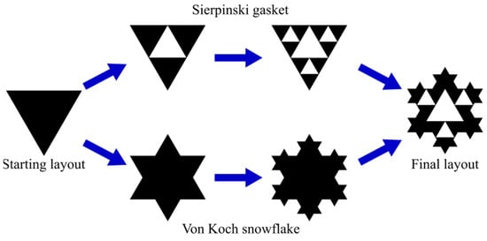
Figure 1.
Design steps of the combined Sierpinski–Von Koch fractal antenna.
From [44], we can calculate the theoretical resonant frequency of the starting antenna as
wherein c is the speed of light, Leff is the effective length of the monopole, and εeff is the effective dielectric constant within the substrate. Assuming from the common rule of the thumb for triangular antennas that Leff ≈ 0.66 Htr1 = 10.10 mm and considering also effects from the length of the feed line, the resonant frequency is expected to be around 4 GHz.
A dimensional drawing of the triangular monopole is reported in Figure 2, and the design parameter values are included in the caption. The frequency response of the triangular monopole is reported in Figure 3a. The antenna has a single resonance frequency at fr1 = 4.32 GHz with a fractional bandwidth (BW − |S11| < −10 dB) of 42.6%. All the simulations herein presented have been carried out with Simulia (Johnston, RI, USA) CST Microwave Studio 2022.
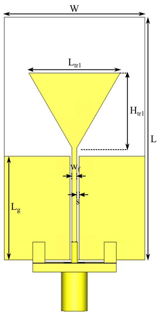
Figure 2.
Dimensional drawing of the starting layout, the triangular monopole. The antenna dimensions are reported in the following: Ltr1 = 17.5 mm, Htr1 = 15.15 mm, W = 27 mm, L = 46.7 mm, wf = 1 mm, s = 0.2 mm, and Lg = 19.95 mm.
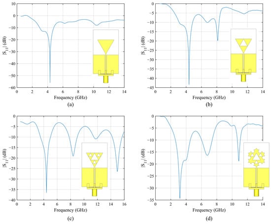
Figure 3.
Evolution of the proposed monopole fractal antenna and simulated frequency response for each step: (a) starting layout (triangular monopole); (b) monopole with the first Sierpinski gasket iteration; (c) monopole with the second Sierpinski gasket iteration; (d) final layout of the monopole (two iteration of Sierpinski gasket and two iteration of the Von Koch snowflake).
The next step has been the implementation of the Sierpinski gasket. The canonical Sierpinski equilateral triangle can be defined by placing the three vertices of an equilateral triangle on an x–y plane and then defining three contraction maps , considering a contraction ratio of r = 1/2 [45], in our case:
The Sierpinski triangle S is defined as the unique nonempty compact set satisfying the self-similarity equation (known as the Hutchinson equation) [45]:
Following these rules, for the first iteration of the Sierpinski gasket, a triangular slot with side Ltr2 = Ltr1/2 = 8.75 mm and height Htr2 = Htr1/2 = 7.57 mm has been inserted upside down in the main body of the triangular monopole, matching its vertices with the side midpoints of the starting triangle. In this way, the starting monopole is divided into three smaller triangles, and the second resonant frequency can be easily calculated, as this time the effective length is simply Leff/2. As shown in Figure 3b, a second resonance appears at fr2 = 8.1 GHz, at nearly twice the frequency of the first one (as expected), with a fractional BW of 5.43%. The first resonance is slightly upshifted at fr1 = 4.39 GHz and maintains the same BW. Then, for the second iteration of the Sierpinski gasket, the same operation is repeated by inserting three triangular slots with side Ltr3 = Ltr2/2 = 4.37 mm and height Htr3 = Htr2/2 = 3.78 mm. This new layout shows an additional resonance at fr3 = 15 GHz, with a fractional BW of 9.8%. The frequency response of the second iteration of the Sierpinski gasket monopole is reported in Figure 3c. The first two resonance frequencies fall at fr1 = 4.4 GHz, with a 34.1% fractional BW, and fr2 = 8.38 GHz, with a 14.5% fractional BW.
A third iteration could be done to obtain a fourth resonance at a higher frequency, but due to the increase in cross-polarization levels for the H-plane cut at high frequencies (see Figure 11 for reference), we preferred to stop at the second iteration.
Finally, the last step in the design process of the proposed monopole is the miniaturization effect achieved using the Von Koch snowflake fractal. The Von Koch curve K can be obtained using four contraction mappings on the same x–y plane considered for the Sierpinski iterations, on each side of an equilateral triangle [46]:
This operation is then iterated on the newly obtained equilateral triangle. To obtain the desired elongation of the outer perimeter of the antenna and, once again, taking into account the limitations of the fabrication process, the second iteration of the Von Koch snowflake is applied, obtaining the final layout of the antenna (see Figure 3d). With the addition of the new triangular protrusions, the antenna maintains its horizontal size (which equals the side of the starting triangle Ltr1), but the vertical size is increased and now equals 4 × Htr1/3 = 20.2 mm. The frequency response of the final antenna layout is reported in Figure 3d. The three operating frequencies are now fr1 = 3.2 GHz (with a 61% fractional BW), fr2 = 6.76 GHz (with a 20.2% fractional BW), and fr3 = 10.87 GHz (with a 3.5% fractional BW). Thanks to the integration of the Von Koch snowflake, all the resonance frequencies are downshifted w.r.t. the second iteration of the Sierpinski gasket, not just the first one. Once again, a third iteration could be possible, this time without the drawback of increased cross-polarization levels, but in this case, we are limited by the fabrication process since the smaller triangles would require much more precision. The monopole equivalent circuit is shown in Figure 4. The coplanar waveguide feed line is modeled as a simple transmission line with characteristic impedance Zf. Since the monopole can be regarded as the combination of three different radiating structures with progressively smaller sizes (approximately halving the dimensions of the initial structure at each iteration), it can be modeled as three parallel resonant RLC circuits, each associated with a different resonance.
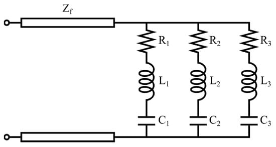
Figure 4.
Equivalent circuit for the proposed fractal monopole antenna.
To offer more insight to the reader about the three useful bandwidths of the proposed fractal antenna, the surface current distribution at 3.2, 6.76, and 10.87 GHz is shown in Figure 5. The current distribution also allows a qualitative analysis of the operation mode for each resonance. Since the CPW-fed planar monopole antenna does not support pure TE/TM modes (like a cavity resonator or a patch antenna), we can interpret each resonance as dominated by an equivalent TE/TM mode based on the current distribution shown in Figure 4. For a current with a predominant vertical component (such as in a canonical monopole), the mode is TM-like, whereas for a current with a predominant transverse component, the mode is TE-like. Thus, the first mode, corresponding to the first resonance at 3.2 GHz, is TM01-like and is equivalent to a quarter-wave monopole antenna since the entire structure radiates. The second resonance, at 6.76 GHz, is still influenced by the fundamental one, with a predominant vertical component and no internal current nodes; however, not the entire structure radiates (only about half of the original one). Hence, this is an upper mode with respect to the fundamental, which can be classified as TM02-like. The last resonance, at 10.87 GHz, exhibits transverse components and current loops, which makes it closer to a TE mode, or possibly to a hybrid TE/TM mode. Therefore, it can be assigned as TE10-like, as the radiating structure is further reduced by approximately half.
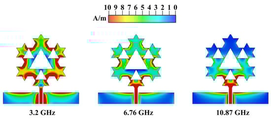
Figure 5.
Surface current distribution for the proposed fractal monopole at the three resonance frequencies.
To sum up the inherent characteristics of the proposed work, the proposed antenna achieves multiband operation through the self-similarity of the Sierpinski gasket, which provides multiple scalable resonances, and through the Von Koch snowflake, which allows frequency downshifting by elongating the current path without significantly altering the profile. While the three bands are not independently tunable in the sense of reconfigurable antennas, each band can be influenced by geometric parameters: e.g., the first band is primarily controlled by Ltr1 and the overall perimeter, the second by the first Sierpinski iteration (Ltr2), and the third by the second iteration (Ltr3). This provides a degree of control that can be exploited during design optimization. In fact, the Sierpinski gasket allows for introducing higher-order resonances with a predictable frequency scaling since each triangle side of the newest iteration is half of the previous one; consequently, the resonance frequency is doubled. In order to help the reader better understand the improvements of the hybridization process, a comparison of the frequency response between the monopole with the second iteration of the Sierpinski gasket, and the final layout is reported in Figure 6, highlighting the miniaturization effect granted by the Von Koch snowflake.
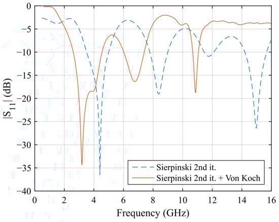
Figure 6.
Comparison between the fractal antenna with Sierpinski second iteration and the final layout to highlight the miniaturization effect granted by the addition of the Von Koch snowflake.
The design also presents clear trade-offs: further Sierpinski iterations could yield additional bands but at the cost of increased cross-polarization levels. Similarly, higher Von Koch iterations would further reduce antenna size, but fabrication tolerances become critical. Finally, while the S- and C-band show wide bandwidths, the X-band operation is narrower, which reflects the typical compromise between miniaturization and high-frequency matching in printed antennas.
In Figure 7, the simulated maximum realized gain and total efficiency of the proposed antenna are shown. The proposed layout has very high efficiency (ranging from 86 to 97%), and the realized gain values, 3.28 dBi at 3.2 GHz, 4.33 dBi at 6.76 GHz, and 4.1 dBi at 10.87 GHz, are consistent with the literature for printed monopoles intended for short-to-medium range satellite links.
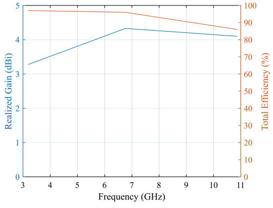
Figure 7.
Simulated maximum realized gain and efficiency of the proposed antenna.
3. Antenna Fabrication and Measurements
A prototype of the proposed antenna has been fabricated using the LPKF (Garbsen, Germany) ProtoMat E44 milling machine on a single-sided Rogers (Chandler, AZ, USA) RO4533 laminate. A photo of the prototype is reported in Figure 8. Then, the frequency response of the fabricated prototype has been measured using an HP (Palo Alto, CA, USA) 8720C VNA after calibration. The comparison between the simulated and measured S11 is reported in Figure 9, showing a very good agreement. From the measurements, the three operating frequency bands can be spotted: from 2.75 to 3.96 GHz, with a 36% fractional BW; from 6.15 to 7.6 GHz, with a 21% fractional BW; and from 11 to 11.15 GHz, with a 1.35% fractional BW. The slight resonance frequency shift (especially at higher frequencies) as well as the difference in S11 minima can be attributed to the manufacturing process, as well as inaccuracies in the measurement system (like internal errors of the VNA and noise introduced by the cables). The antenna radiation pattern and maximum realized gain have also been measured in anechoic chamber following the methodology described in [47] and employing a double ridge horn antenna type HF907, at 3.35 GHz, 7 GHz, and 11.05 GHz, corresponding to the three resonance frequencies of the fabricated prototype. The comparison between the simulated and measured far-field pattern and maximum realized gain for the proposed antenna is reported in Figure 10 and Figure 11, respectively, showing a good agreement. The measured maximum realized gains are 2.8, 4.02, and 3.75 dBi for the three resonance frequencies, which are consistent with the gain of monopoles and planar antennas employed in short-to-medium satellite communications. In this case, the small discrepancy between simulated and measured results can be ascribed to some minor inaccuracy in the measurement process. A photo of the measurement setup is shown in Figure 12.
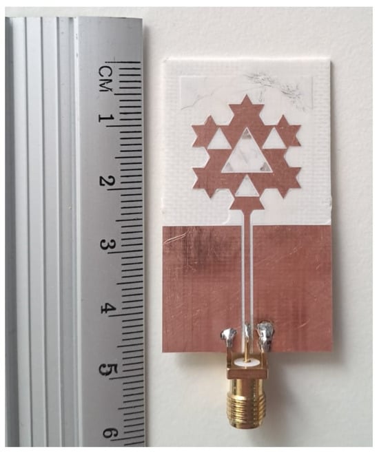
Figure 8.
Photo of the fabricated fractal monopole antenna.
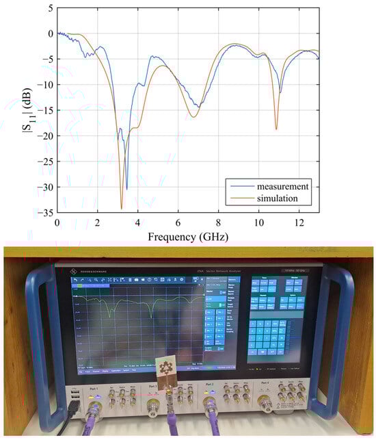
Figure 9.
Comparison between simulated and measured |S11| of the proposed antenna and screenshot of the measured frequency response with the VNA.
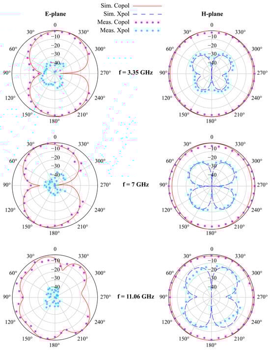
Figure 10.
Comparison between simulated and measured far-field radiation pattern (E-plane on the left, H-plane on the right) for the proposed Sierpinski–Von Koch fractal monopole antenna for the three measured resonance frequencies (3.35, 7, and 11.06 GHz). Note: simulated cross-polarization levels for the E-plane cuts are not shown because they are lower than −50 dBi.
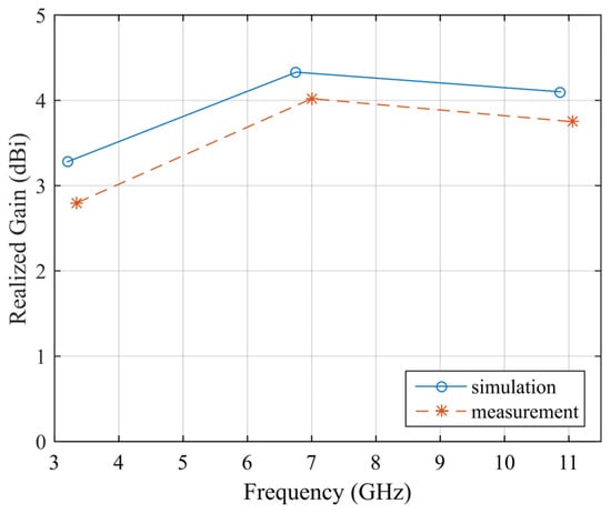
Figure 11.
Comparison between simulated and measured maximum realized gain of the proposed antenna.
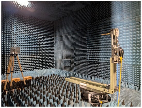
Figure 12.
Photo of the measurement setup for the far-field and maximum realized gain measurements.
Observing Figure 10, as expected, the antenna shows a dipole-like omnidirectional radiation pattern. It should be noted that the simulated cross-polarization levels along the E-plane cuts are not displayed because they are lower than −50 dBi. It is also interesting to notice how the cross-polarization levels grow with the frequency for the H-plane cuts. As already mentioned, this is a compelling reason to avoid the fourth resonance that most likely would have higher cross-polarization levels. There are also some measurement points missing from the right side of the E-plane cuts (ranging from 240° to 300°), which have been adulterated by the presence of the measurement cable and the antenna support; thus, they have not been taken into account. However, since the other measured far-field points are very close to the simulation, we strongly stand by the claim of general good agreement between simulations and measurements.
4. Comparison with the State of the Art
In order to provide a fair comparison with the current state of the art in multiband antenna design, representative antenna results reported in the literature over the past five years are summarized in Table 1. The proposed antenna stands out for its ability to achieve high performance in terms of efficiency, bandwidth, and geometric controllability, while maintaining a simple and compact structure. The combination of Sierpinski and Von Koch fractal geometries enables scalable tuning and predictable resonance behavior, together with an ultra-low profile (0.006 λ0) and overall dimensions compatible with compact satellite platforms such as CubeSats.

Table 1.
Comparison with the state-of-the-art multiband antennas of the last five years.
Compared with the works reported in [11,12,13,14,15,16,17,18,19,20,21,22,23,24,25,26,27,28,29], the proposed design represents a well-balanced compromise between performance and manufacturability. Although some antennas achieve higher gain [12,21,24,27,28] or incorporate advanced features such as circular polarization [23,28] and reconfigurability [25], these advantages are often obtained at the expense of structural simplicity, compactness, or energy efficiency. Other designs focus on flexibility for wearable or navigation applications [14,22,26], typically resulting in lower gain and geometries that are less suitable for stringent spatial constraints. In contrast, antennas such as those in [13,19,20] rely on multilayer or MIMO configurations with increased geometrical complexity, while the solutions proposed in [17,18] provide wide coverage or independent tuning at the cost of significantly larger footprints.
The proposed design occupies a well-balanced position among the reported solutions, providing a compact, efficient, and easily integrable multiband antenna with competitive measured performance and a structure well suited to practical satellite communication scenarios. Based on the comparison presented in Table 1, the proposed monopole fractal antenna can be regarded as a simple, compact, and low-profile candidate, offering relatively wide operating bandwidths—particularly in the first two bands—together with high radiation efficiency. These characteristics make the antenna suitable for satellite communication applications in the S-, C-, and X-bands.
To further highlight the strengths of the proposed layout, a radar plot comparing the performance of the most representative antennas listed in Table 1 is shown in Figure 13. The evaluation is based on the number of operating bands, mean fractional bandwidth, mean gain, physical size, and structural complexity. Each parameter is normalized and assigned a score ranging from 0 to 1 (with 1 corresponding to a very simple layout in terms of complexity and to a very compact footprint in terms of size). Only antennas with an aggregate score greater than 3 are included in the radar plot.
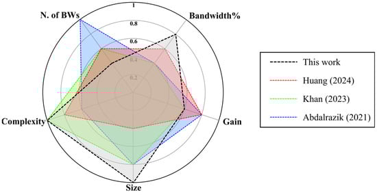
Figure 13.
Radar plot of the performance of the most prominent antennas from Table 1 (i.e., Huang [18], Khan [23], and Abdalrazik [28]), ranked by number of operating bandwidths, mean fractional bandwidth, mean gain, size, and complexity.
5. Conclusions
This paper proposes a fractal monopole antenna for multiband satellite communication applications. The antenna exploits the combined effects of the Sierpinski gasket fractal, which enables the generation of multiple resonances, and the Von Koch snowflake geometry, which increases the outer perimeter of the radiator and provides a miniaturization effect, without the need for additional matching structures or defected ground planes. The close agreement between simulated and measured results demonstrates that the proposed monopole operates in three frequency bands relevant to satellite communications, namely the S-band (2.75–3.96 GHz, 36% bandwidth), C-band (6.15–7.6 GHz, 21% bandwidth), and X-band (11–11.15 GHz, 1.35% bandwidth). High radiation efficiency, ranging from 86% to 97%, is achieved across the operating bands, with measured gains of 2.8 dBi, 4.02 dBi, and 3.75 dBi for the S-, C-, and X-bands, respectively. The antenna features a compact footprint of 0.52λ0 × 0.3λ0 × 0.006λ0, making it well suited for multiband satellite platforms.
It is worth noting that the adoption of more advanced fabrication processes could further enhance the proposed design by enabling (i) the implementation of a higher-order Von Koch iteration to achieve additional miniaturization and (ii) the scalable adaptation of the antenna geometry to higher-frequency satellite bands, such as Ku-, K-, and Ka-bands. Overall, the proposed antenna compares favorably with recent state-of-the-art designs in terms of efficiency, bandwidth, and compactness, while maintaining an ultra-low profile. These characteristics make it a strong candidate for integration into space-constrained satellite communication systems. Moreover, this work may pave the way toward a new class of hybrid fractal antennas based on the systematic combination of established fractal geometries to achieve enhanced electromagnetic performance.
Author Contributions
Conceptualization, G.M. (Giacomo Muntoni); methodology, G.M. (Giacomo Muntoni) and A.M.; software, G.M. (Giacomo Muntoni); validation, G.M. (Giacomo Muntoni), A.M., D.G. and M.S.; investigation, G.M. (Giacomo Muntoni) and A.M.; data curation, G.M. (Giacomo Muntoni), A.M., D.G. and M.S.; writing—original draft preparation, G.M. (Giacomo Muntoni); writing—review and editing, G.M. (Giacomo Muntoni), A.F. and G.M. (Giuseppe Mazzarella); visualization, A.F.; supervision, A.F. and G.M. (Giuseppe Mazzarella). All authors have read and agreed to the published version of the manuscript.
Funding
This research and the APC were funded by Ministero delle Imprese e del Made in Italy (MIMIT) through the project “Tecnologie ICT e dell’Industria 4.0 per l’Analisi e l’Ingegnerizzazione dei Sistemi Alimentari Complessi per la produzione di pani artigianali locali ad alto valore aggiunto –AISAC”, grant number: NM_RICALTRO_WP_CTC_2023_AISAC_FANTI.
Data Availability Statement
The original contributions presented in this study are included in the article. Further inquiries can be directed to the corresponding author.
Conflicts of Interest
The authors declare no conflicts of interest.
References
- Ding, Y.; Jiao, Y.C. Design of a Multiband Quasi-Yagi-Type Antenna with CPW-to-CPS Transition. IEEE Antennas Wirel. Propag. Lett. 2011, 10, 1120–1123. [Google Scholar] [CrossRef]
- Deepu, V.; Raj, R.K.; Joseph, M.; Suma, M.N.; Mohanan, P. Compact Asymmetric Coplanar Strip Fed Monopole Antenna for Multiband Applications. IEEE Trans. Antennas Propag. 2007, 55, 2351–2357. [Google Scholar] [CrossRef]
- Lu, J.H.; Chou, W.C. Planar Dual U-Shaped Monopole Antenna With Multiband Operation for IEEE 802.16e. IEEE Antennas Wirel. Propag. Lett. 2010, 9, 1006–1009. [Google Scholar] [CrossRef]
- Sanz-Izquierdo, B.; Batchelor, J.C.; Langley, R.J.; Sobhy, M.I. Single and double layer planar multiband PIFAs. IEEE Trans. Antennas Propag. 2006, 54, 1416–1422. [Google Scholar] [CrossRef]
- Luo, Y.; Zhu, L.; Liu, Y.; Liu, N.W. Multiband Monopole Smartphone Antenna With Bandwidth Enhancement Under Radiation of Multiple Same-Order Modes. IEEE Trans. Antennas Propag. 2022, 70, 2580–2592. [Google Scholar] [CrossRef]
- Boukarkar, A.; Lin, X.Q.; Jiang, Y.; Yu, Y.Q. Miniaturized Single-Feed Multiband Patch Antennas. IEEE Trans. Antennas Propag. 2017, 65, 850–854. [Google Scholar] [CrossRef]
- Lee, W.S.; Lim, W.G.; Yu, J.W. Multiple band-notched planar monopole antenna for multiband wireless systems. IEEE Microw. Wirel. Compon. Lett. 2005, 15, 576–578. [Google Scholar]
- Shoaib, S.; Shoaib, I.; Shoaib, N.; Chen, X.; Parini, C.G. Design and Performance Study of a Dual-Element Multiband Printed Monopole Antenna Array for MIMO Terminals. IEEE Antennas Wirel. Propag. Lett. 2014, 13, 329–332. [Google Scholar] [CrossRef]
- Antoniades, M.A.; Eleftheriades, G.V. A Compact Multiband Monopole Antenna With a Defected Ground Plane. IEEE Antennas Wirel. Propag. Lett. 2008, 7, 652–655. [Google Scholar] [CrossRef]
- Hu, W.; Yin, Y.Z.; Yang, X.; Fei, P. Compact Multiresonator-Loaded Planar Antenna for Multiband Operation. IEEE Trans. Antennas Propag. 2013, 61, 2838–2841. [Google Scholar] [CrossRef]
- Chandan, R.K. Triple-Mode CMA-Optimized HMSIW Antenna With Dual Slits for Smart 5G IoT Platforms. IEEE Internet Things J. 2026, 13, 3529–3535. [Google Scholar] [CrossRef]
- Ma, X.; Zong, Y.; Zhang, P.; Chen, J.; Ren, Z.; Liu, Z.; Li, C. Design of Multiband Patch Antennas Using Adaptive Topology Optimization Method. IEEE Trans. Antennas Propag. 2026, 74, 38–50. [Google Scholar] [CrossRef]
- Su, S.W.; Huang, J.C.; Yu, T.C.; Lu, J.H. Multimode, Printed Mobile-Unit Loop for Wi-Fi 8 and 6G Upper Mid-Band Applications. IEEE Antennas Wirel. Propag. Lett. 2026, 25, 254–258. [Google Scholar] [CrossRef]
- Gan, L.; Huang, H.; Liu, X.; Yu, S.; Jing, X.; Cui, Y. A Low-Profile Flexible Tri-Band Antenna for Both Communication and Navigation Uses on AAVs. IEEE Antennas Wirel. Propag. Lett. 2025, 24, 4920–4924. [Google Scholar] [CrossRef]
- Aziz, R.S.; Koziel, S.; Pietrenko-Dabrowska, A. A compact tri-band omnidirectional antenna design for CubeSat applications. Sci. Rep. 2025, 15, 11908. [Google Scholar] [CrossRef] [PubMed]
- Khan, S.; Khan, O.; Raheel, K.; Shah, S.A.; Malik, B.T.; Khan, S.; Gohar, N.; Koziel, S. A Highly Compact Split Ring Resonator-Based Rectangular Dielectric Resonator Antenna With Multiband Characterization. IEEE Access 2025, 13, 2360–2376. [Google Scholar] [CrossRef]
- Saeed, M.J.; Tahseen, M.M.; Kishk, A.A. Compact Multiband Omnidirectional Antenna for Maximizing Frequency Coverage. IEEE Antennas Wirel. Propag. Lett. 2025, 24, 597–601. [Google Scholar] [CrossRef]
- Huang, W.; Ji, L.-Y.; Zhou, S.-G. Multiband Modified Yagi Antenna in a Shared Transverse Aperture. IEEE Antennas Wirel. Propag. Lett. 2024, 23, 2583–2587. [Google Scholar] [CrossRef]
- Li, Y.; Yang, W.; Xue, Q.; Che, W. A Miniaturized Dual-Polarized Tri-Band Antenna Based on Multimode and Stacked Scheme for Multiband Aperture-Shared Base-Station Applications. IEEE Trans. Antennas Propag. 2024, 72, 4647–4652. [Google Scholar] [CrossRef]
- Sarfraz, H.; Khan, S.; Khan, N.; Gohar, N.; Shah, S.A.A.; Nasir, J.; Dalarsson, M. Next-Generation Multiband Wireless Systems: A Compact CSSR-Based MIMO Dielectric Resonator Antenna Approach. IEEE Access 2024, 12, 4910–4924. [Google Scholar] [CrossRef]
- Yang, S.; Tong, F.; Chu, J.; Chen, Y.; Zhao, Z.; Fang, Z.; Zheng, Y.; Wang, W. Compact Tetracyclic Nested AMC-Backed Multiband Antenna With High OoB Rejection and Enhanced Gain Radiation for IIoV-Based Sensing and Communication. IEEE Internet Things J. 2024, 11, 2819–2829. [Google Scholar] [CrossRef]
- Xiao, Y.; Zu, H.; Song, R.; Xin, Y.; Xi, Y.; Huang, G.L.; Wu, B.; He, D. Multiband and Low-Specific-Absorption-Rate Wearable Antenna With Low Profile Based on Highly Conductive Graphene Assembled Film. IEEE Antennas Wirel. Propag. Lett. 2023, 22, 2195–2199. [Google Scholar] [CrossRef]
- Khan, A.; He, Y.; He, Z.; Chen, Z.N. A Compact Quadruple-Band Circular Polarized MIMO Antenna With Low Mutual Coupling. IEEE Trans. Circuits Syst. II 2023, 70, 501–505. [Google Scholar] [CrossRef]
- Farahat, A.E.; Hussein, K.F.A.; El-Hassan, M.A. Design Methodology of Multiband Printed Antennas for Future Generations of Mobile Handsets. IEEE Access 2022, 10, 75918–75931. [Google Scholar] [CrossRef]
- Padmanathan, S.; Al-Hadi, A.A.; Elshirkasi, A.M.; Al-Bawri, S.S.; Islam, M.T.; Sabapathy, T.; Jusoh, M.; Akkaraekthalin, P.; Soh, P.J. Compact Multiband Reconfigurable MIMO Antenna for Sub-6 GHz 5G Mobile Terminal. IEEE Access 2022, 10, 60241–60252. [Google Scholar] [CrossRef]
- Li, H.; Du, J.; Yang, X.-X.; Gao, S. Low-Profile All-Textile Multiband Microstrip Circular Patch Antenna for WBAN Applications. IEEE Antennas Wirel. Propag. Lett. 2022, 21, 779–783. [Google Scholar] [CrossRef]
- Claus, N.; Verhaevert, J.; Rogier, H. High-Performance Air-Filled Multiband Antenna for Seamless Integration Into Smart Surfaces. IEEE Antennas Wirel. Propag. Lett. 2021, 20, 2260–2264. [Google Scholar] [CrossRef]
- Abdalrazik, A.; Gomaa, A.; Kishk, A.A. A Hexaband Quad-Circular-Polarization Slotted Patch Antenna for 5G, GPS, WLAN, LTE, and Radio Navigation Applications. IEEE Antennas Wirel. Propag. Lett. 2021, 20, 1438–1442. [Google Scholar] [CrossRef]
- Boursianis, A.D.; Papadopoulou, M.S.; Pierezan, J.; Mariani, V.C.; Coelho, L.S.; Sarigiannidis, P.; Koulouridis, S.; Goudos, S.K. Multiband Patch Antenna Design Using Nature-Inspired Optimization Method. IEEE Open J. Antennas Propag. 2021, 2, 151–162. [Google Scholar] [CrossRef]
- Congiu, S.; Mazzarella, G. A Tri-Band Printed Antenna Based on a Sierpinski Gasket. J. Electromagn. Waves Appl. 2007, 21, 2187–2200. [Google Scholar] [CrossRef]
- Weng, W.-C.; Hung, C.-L. An H-Fractal Antenna for Multiband Applications. IEEE Antennas Wirel. Propag. Lett. 2014, 13, 1705–1708. [Google Scholar] [CrossRef]
- Choukiker, Y.K.; Sharma, S.K.; Behera, S.K. Hybrid Fractal Shape Planar Monopole Antenna Covering Multiband Wireless Communications with MIMO Implementation for Handheld Mobile Devices. IEEE Trans. Antennas Propag. 2014, 62, 1483–1488. [Google Scholar] [CrossRef]
- Pourahmadazar, J.; Ghobadi, C.; Nourinia, J.; Shirzad, H. Multiband Ring Fractal Monopole Antenna for Mobile Devices. IEEE Antennas Wirel. Propag. Lett. 2010, 9, 863–866. [Google Scholar] [CrossRef]
- Chang, D.-C.; Zeng, B.-H.; Liu, J.-C. CPW-Fed Circular Fractal Slot Antenna Design for Dual-Band Applications. IEEE Trans. Antennas Propag. 2008, 56, 3630–3636. [Google Scholar] [CrossRef]
- Werner, D.H.; Ganguly, S. An Overview of Fractal Antenna Engineering Research. IEEE Antennas Propag. Mag. 2003, 45, 38–57. [Google Scholar] [CrossRef]
- Puente-Baliarda, C.; Romeu, J.; Pous, R.; Cardama, A. On the Behavior of the Sierpinski Multiband Fractal Antenna. IEEE Trans. Antennas Propag. 1998, 46, 517–524. [Google Scholar] [CrossRef]
- Yu, Z.; Yu, J.; Ran, X.; Zhu, C. A Novel Koch and Sierpinski Combined Fractal Antenna for 2G/3G/4G/5G/WLAN/Navigation Applications. Microw. Opt. Technol. Lett. 2017, 59, 2147–2155. [Google Scholar] [CrossRef]
- Chen, W.-L.; Wang, G.-M.; Zhang, C.-X. Small-Size Microstrip Patch Antennas Combining Koch and Sierpinski Fractal-Shapes. IEEE Antennas Wirel. Propag. Lett. 2008, 7, 738–741. [Google Scholar] [CrossRef]
- Zhang, X.; Sun, F.; Zhang, G.; Hou, L. Compact UHF/VHF Monopole Antennas for CubeSats Applications. IEEE Access 2020, 8, 133360–133366. [Google Scholar] [CrossRef]
- Muntoni, G.; Montisci, G.; Melis, A.; Lodi, M.B.; Curreli, N.; Simone, M.; Tedeschi, G.; Fanti, A.; Pisanu, T.; Kriegel, I.; et al. A Curved 3D-Printed S-Band Patch Antenna for Plastic CubeSat. IEEE Open J. Antennas Propag. 2022, 3, 1351–1363. [Google Scholar] [CrossRef]
- Sun, Z.; Liang, Z.; Lv, X.; Zhou, Y.; Liu, S.; Luo, Z.; Yang, Y. C-/Ka-Band Low-Profile Circularly Polarized Shared-Aperture Antenna for CubeSat Communications. IEEE Trans. Antennas Propag. 2025, 73, 1221–1226. [Google Scholar] [CrossRef]
- Yu, Z.; Chen, C.; Chen, W.D.; Zhang, X.; Lu, J.G.; Zhang, X.L.; Che, B.J.; Wang, Q. A Low-Profile LTCC Phased Array Antenna with Wideband and High-Gain for X-Band Satellite Communications. IEEE Trans. Antennas Propag. 2025, 73, 659–664. [Google Scholar] [CrossRef]
- Rogers Corporation RO4500TM Laminates. Available online: https://www.rogerscorp.com/advanced-electronics-solutions/ro4000-series-laminates/ro4500-laminates (accessed on 21 January 2026).
- Ray, K.P. Design Aspects of Printed Monopole Antennas for Ultra-Wide Band Applications. Int. J. Antennas Propag. 2008, 2008, 713858. [Google Scholar] [CrossRef]
- Hutchinson, J.E. Fractals and Self-Similarity. Indiana Univ. Math. J. 1981, 30, 713–747. [Google Scholar] [CrossRef]
- Falconer, K. Fractal Geometry: Mathematical Foundations and Applications; Wiley: Hoboken, NJ, USA, 2003. [Google Scholar]
- IEEE 149-2021; IEEE Recommended Practice for Antenna Measurements. IEEE: New York, NY, USA, 2022.


Disclaimer/Publisher’s Note: The statements, opinions and data contained in all publications are solely those of the individual author(s) and contributor(s) and not of MDPI and/or the editor(s). MDPI and/or the editor(s) disclaim responsibility for any injury to people or property resulting from any ideas, methods, instructions or products referred to in the content. |
© 2026 by the authors. Licensee MDPI, Basel, Switzerland. This article is an open access article distributed under the terms and conditions of the Creative Commons Attribution (CC BY) license.