Abstract
This paper proposes an underwater free-space optical code division multiple-access (FSO-CDMA) communication system that integrates differential pulse position modulation (DPPM) with a developed hybrid prime code (HPC) and Manchester encoding, alongside a multiple-access interference cancellation (MAIC) receiver. The system is designed to address the challenges posed by underwater turbulence, absorption, and scattering. A 1-watt laser source operating at a wavelength of 455 nm is utilized to mitigate these effects, thereby reducing link absorption, scattering, and attenuation. The MAIC receiver is employed to minimize noise and interference, significantly enhancing the system’s bit-error rate (BER) performance under turbulent conditions. The paper details the construction and correlation analysis of the HPC, and investigates both instantaneous and average BER performance based on the proposed modulation-coding technique and MAIC receiver. Results demonstrate that the proposed system achieves a 438 m link distance with an 8.33 Gbps data rate and 1.33 Tbps × user network throughput over a 184,900 m2 coverage area, maintaining a BER of 10−9.
1. Introduction
This paper provides an overview of recent advancements in optical wireless communication (OWC). Wireless communication (WC) has become ubiquitous across a diverse range of devices globally. The application of WC in terrestrial and underwater environments is of significant interest for industrial, military, and scientific communities [1,2]. Underwater acoustic systems, renowned for their ability to transmit over extended distances, have seen substantial success, fostering continued research and technological improvements. Numerous studies have focused on enhancing the performance of these acoustic communication channels [3,4,5,6,7]. Despite advancements, acoustic communication is constrained by physical factors that limit bandwidth, leading to a high potential for significant transmission losses, along with challenges such as time-varying multipath propagation and Doppler spread [8,9,10,11,12,13].
These limitations hinder underwater vehicles from transmitting high-definition, real-time video feeds via acoustic methods. Therefore, complementary technologies are essential for achieving high-bandwidth multimedia underwater communication. Real-time video transmission, crucial for submarine teleoperation and remote monitoring of underwater stations and ports, is an area of significant interest [14,15,16,17]. While radiofrequency (RF) waves are prevalent and widely used in global communications, their effectiveness underwater is severely compromised due to strong attenuation [18].
Furthermore, conventional underwater acoustic communication is vulnerable to malicious attacks due to its intrinsic performance characteristics, which include high bit error rates (BERs), substantial and variable propagation delays, and limited bandwidth [19]. Visible-light communication (VLC) presents a potential solution to these issues. VLC utilizes the visible light spectrum (400–700 nm) for data transmission, adapting it from its primary use in illumination [20,21,22,23,24,25,26,27]. Underwater optical wireless communication (UOWC) systems employ laser diodes (LDs) as light sources, offering advantages such as broader modulation bandwidth compared to LEDs, although LEDs are favoured for medium-bit-rate applications due to their power efficiency, cost-effectiveness, and durability. Despite these benefits, UOWC performance is limited to short ranges. As commercial submarine optical communication systems become available [28,29], extensive research continues on methods to extend optical signal range. Although UOWC cannot entirely replace acoustic communication, hybrid acoustic–optical systems have shown promise and warrant further exploration [30,31,32,33].
OWC technologies offer numerous advantages, including high data rates, secure connections, and cost benefits due to the absence of regulatory fees associated with optical bands [34]. However, significant challenges remain, such as water’s absorption of optical signals and scattering caused by particles. Nonetheless, saltwater’s lower absorption in the blue/green wavelengths of the visible spectrum presents opportunities for high-speed connections depending on water conditions. In clear waters, attenuation is minimal around 455 nm, whereas in turbid waters, it shifts to higher wavelengths, such as 540 nm in coastal areas [12].
In this study, Manchester encoding is applied to enhance network performance. The impact of multiple-access interference (MAI) is considered alongside other noise sources from the channel and system. Typically, a differential pulse position modulation (DPPM) code-division multiple-access (CDMA) network with MAI cancellation (MAIC) proves effective as user numbers increase [3,34,35]. To further improve performance, high-power control (HPC) is employed to manage the signal-to-noise ratio and interference among multiple users’ signals. The analysis includes a link budget assessment and the effects of signal attenuation at a 455 nm wavelength. Additionally, the influence of coding parameters and system configuration on bit error rate (BER) performance and transmission range is examined. The study also addresses the impact of transmitter–receiver misalignment.
The paper is structured in seven sections. Section 2 details the proposed system’s block diagrams for the transmitter and receiver and their descriptions. Section 3 discusses the construction principles and correlation properties of HPC. Section 4 presents an underwater link power budget analysis using the gamma–gamma model. Section 5 investigates system BER performance in relation to transmission distance, system configuration, and coding parameters. Section 6 evaluates BER performance against optical signal-to-noise ratio, received optical power, and transmission distance and explores the impact of coding parameters. Finally, Section 7 summarizes the simulation results and concludes the study.
2. Proposed System Block Diagram
Figure 1 show the general block diagram of the FSO-CDMA system underwater [1]. This system consists of an OCDMA transmitter, laser pointing and tracking system, FSO underwater communication channel, photodetector pointing and tracking system, and OCDMA receiver. In the OCDMA transmitter shown in Figure 2, the data is firstly modulated using differential pulse position modulator to minimize the pulse width and reduce the channel dispersion. This DPPM signal is encoded using a Manchester line encoder to improve the signal properties. Before transmission the encoded data is encoded again using a CDMA HPC encoder to spread the data, prevent the MAI, and ensure system security. The laser source used operated at the 455 nm wavelength of the blue light to minimize the signal attenuation through the FSO channel underwater [2,3,4,5,6,7,8,9,10]. The pointing and tracking systems are used to achieve line of sight (LOS) communication between the transmitter and receiver. Pointing–tracking assumptions include using a closed-loop control system to correct errors and using a beacon or celestial images for calibration. The signal-to-noise ratio (SNR) is a primary factor in determining the precision of pointing errors. Pointing errors reduce the SNR, which in turn decreases the system’s effective range and increases the bit error rate (BER), especially at higher bit rates. The effect of both the incident angle and pointing jitter is typically a reduction in the received signal power, which decreases SNR, limits maximum range, and increases BER.
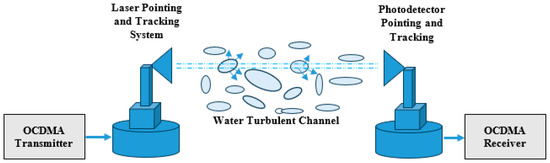
Figure 1.
General block diagram of underwater LOS communication system [36].
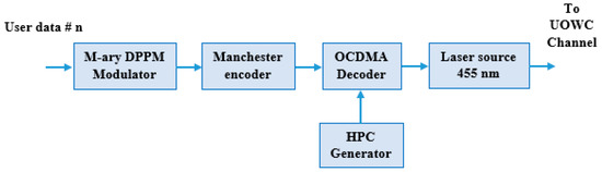
Figure 2.
Proposed transmitter block diagram for user # n.
Figure 3 illustrates the MAIC receiver. In this figure, the HPC sequence of data #n incoming from the optical network is decoded using the optical delay lines and the optical received signal is converted to an electrical one using the p-type intrinsic n-type semiconductor (PIN) photodetector. The output electrical signal from the photodetector is typically integrated, sampled over the half-pulse duration due to the use of the Manchester line encoding technique, and demodulated by the DPPM demodulator to extract the intended data signal #n, where the incoming signal from the optical network passes through two decoding branches. The upper branch decoder is the desired optical decoder used to decode the HPC sequence of user #n, while the lower branch decoder is used as a reference decoder to decode only interference and noise. Finally, the output of the lower decoder has been subtracted from the output of the upper decoder to extract the desired signal from the interference and noise. After that, the DPPM demodulator is utilized to extract the original transmitted signal of user #n from the DPPM signal.
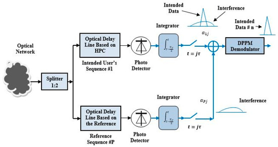
Figure 3.
Proposed multiple-access interference cancellation receiver of user # n.
3. HPC Construction
As described in [36], a hybrid prime code (HPC) sequence can be constructed using two or more distinct prime numbers. For simplicity, let us consider two prime numbers, P1 and P2, with P2 being greater than P1. Historically, the number of code words generated by a prime number is equal to that prime number. For instance, if P1 = 5, then five code words can be generated, with each code word consisting of five chips. In each code word, only one chip is set to logic HIGH, while the remaining chips are set to logic ZERO. The position of the HIGH chip can be defined by , where , representing the number of shifts required to place the HIGH chip from left to right. To illustrate further, if P1 = 5 and P2 = 7, two groups of code words can be generated, one associated with P1 = 5 and the other with P2 = 7, and the resulting code words can be listed as follows:
| for P1 = 5 | for P2 = 7 |
| X01 = [1 0 0 0 0] − 0 shift X11 = [0 1 0 0 0] − 1 shift X21 = [0 0 1 0 0] − 2 shift X31 = [0 0 0 1 0] − 3 shift X41 = [0 0 0 0 1] − 4 shift | X02 = [1 0 0 0 0 0 0] − 0 shift X12 = [0 1 0 0 0 0 0] − 1 shift X22 = [0 0 1 0 0 0 0] − 2 shift X32 = [0 0 0 1 0 0 0] − 3 shift X42 = [0 0 0 0 1 0 0] − 4 shift X52 = [0 0 0 0 0 1 0] − 5 shift X62 = [0 0 0 0 0 0 1] − 6 shift |
Based on the branching operation, we can use the above two groups to construct the below two tables. The results from each table are the code sequence tree and the folded code sequence tree as shown below.
Each tree in Table 1 and Table 2 consists of and number of code sequences, respectively, where and . The relation between the two numbers can be defined as where the number 1 represents the number of code sequences not used for the HPC construction from these two trees. In the proposed example, the unused code sequence is the highlighted code sequences in Table 2.

Table 1.
Code sequence tree for p = 5.
Table 2.
Code sequence tree for p = 7.
3.1. HPC Construction Steps
- The first step: the first tree sequences arranged row by row vertically in one column as in column 1, Table 3;
Table 3. HPC sequences for P1 = 5 and P2 = 7.
- The third step: the merged code sequences in column 2, Table 3 must be rotated horizontally clockwise until the first code word becomes the last code word.
3.2. Correlation Properties
The auto- and cross-correlation values of the proposed HPC sequences can be calculated using the following equation.
In more detail, this equation illustrates the following:
- represents the peak value of the auto-correlation (i.e., the correlation of a code sequence with itself) at the sampling time. In this example, the sampling time is equal to , where is an integer corresponding to the number of code words used to create the sequence from the first tree, denotes the number of prime numbers employed to construct the code sequence, and is the duration of a single chip time.
- At the sampling time, the cross-correlation value between two different codes equals “0” or “1”.
- For three prime numbers, if the number of code words represents the first tree of the minimum prime number n = 2, the peak value of auto-correlation will equal 3n = 6 and the cross-correlation will remain 0 or 1. The hardware complexity is not changed compared to the construction complexity of the two prime HPCs, but the software complexity has been increased for the used memory programming, and the programming algorithm depends on the code construction steps illustrated above.
3.3. Correlation Results
Figure 4 shows the simulation results for the auto-correlation values of different HPC sequences such as , , , and . These results show that at the sampling time, the peak auto-correlation value equals 4 for each code sequence. This is because each code sequence consists of four ONEs that represent the code weight and prove Equation (1). Also, the side lobe values do not exceed 1; this helps the receiver to make the good decision to extract the data from the received data, which contain the data and interference and consequently enhance the system’s BER performance.
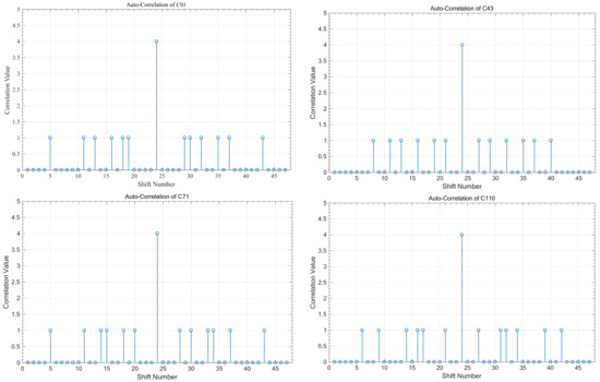
Figure 4.
Auto-correlation of sequences; .
Figure 5 illustrates the cross-correlation values between different code sequences, focusing on both sequences within the same group and those from different groups. It is evident that when two code sequences belong to the same group, the cross-correlation value is “ZERO” at each synchronized time corresponding to the shift number “24,” demonstrating perfect orthogonality and resulting in zero interference on the receiver side. Additionally, the simulation results show that when comparing code sequences from different groups, the cross-correlation value at the sampling time can be either “0” or “1,” highlighting the differences in interference behaviour based on group affiliation.
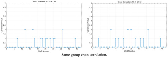
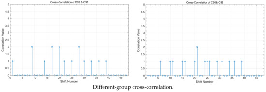
Figure 5.
Cross-correlation between different sequences in the same group and different groups; .
From the above results, we can identify the following items that summarize the advantages of the proposed HPC sequences over the other famous sequences used in the CDMA systems like, the OOCs and the MPC [37,38,39,40,41,42,43,44,45,46,47].
- In general, the HPC cross-correlation values take “0” or “1” at the synchronized sampling time.
- A new idea is to construct orthogonal codes using two or more prime numbers which increase the number of code sequences and consequently increase the number of simultaneous users sharing the network with good correlation properties.
- They can be generated using simple optical delay lines or Bragg grating to minimize the size of the CDMA encoder.
- Table 4 illustrates the comparison between MPC family, double-length MPC (DLMPC), weighted MPC (WMPC), and the proposed HPC in terms of channel model, kind of receiver, BER performance, and maximum available number of users that can share the network simultaneously.
Table 4. Comparison between the MPC family and the proposed HPC.
4. Underwater Channel Model
Before the channel model analysis, we are defining the model parameters for more simplicity and clearance [5,6].
- —The value of optical power transmitted from the blue light laser diode.
- —The value of optical power received by the PIN photodetector.
- —The transmitter optical efficiency.
- —The receiver optical efficiency.
- —The angle between the light trajectory and the perpendicular on the transmitter–receiver planes.
- —The area of photodetector receiver aperture.
- —The laser half divergence angle.
- —The underwater channel attenuation coefficient.
- —The irradiance probability density function.
- —The scintillation indexes.
- —The scintillation index representation parameter.
- —Gamma function.
- —The link transmission distance.
- —The normalized intensity variance.
- —The receiver aperture area.
- —The absorption coefficient of pure water.
- —The dimensionless specific absorption coefficient for chlorophyll.
- —The chlorophyll concentration.
- —The scattering coefficient.
- —The absorption coefficient.
Equation (1) presents the optical power received considering the effect of underwater attenuation function of the wavelength variation, laser beam divergence, transmission distance, photodetector aperture area, and angle between the light beam and the perpendicular on the laser and photodetector planes.
Modelling underwater optical wireless communication (UOWC) channels must account for the significant effects of scintillation. As laser light beams travel through water, turbulence arises, characterized by chaotic variations in water velocity and pressure. This turbulence changes the water’s properties, leading to fluctuations in the refractive index and consequently affecting optical power, which degrades system performance [22]. Although various UOWC system models represent the effects of turbulence, the gamma–gamma model is particularly suited to weak turbulence conditions. The impact of turbulence on system performance is analyzed using the probability density function of irradiance, . Different UOWC channel models are detailed in [11] using the following equations:
where is the scintillation index defined by (5) and represented by a parameter function as in (4), and is the gamma function of the parameter
The parameters and are defined by (6) and (7), respectively, where and is the phase constant or the wave number.
In underwater optical transmission, two major challenges are the high absorption of optical signals by the water medium and scattering caused by particles in seawater. Seawater exhibits lower absorption and, consequently, reduced attenuation in the visible light spectrum, particularly within the blue-green range of 450 to 470 nm. The lowest attenuation is observed in clear ocean water at 460 nm, while this wavelength range shifts to 530–550 nm in coastal waters [5,6,7,8,9,10,11,12,13,14,15,16,17,18,19,20,21]. The spectral attenuation coefficient, which combines both scattering and absorption coefficients, characterizes light propagation in water, particularly in areas with minimal scattering. Factors such as particle algal/sediment matter, dissolved pigmented organic content, and water molecules contribute to this attenuation.
In addition to the impact of wavelength on absorption, the absorption and scattering coefficients are significantly influenced by the type of particles present and the level of turbidity. Phytoplankton and organic particles are the primary contributors to particle content in seawater that affect light properties. The first type of particles, phytoplankton, strongly absorbs the blue and red wavelengths of light. In murky water, photon scattering results in reduced optical power reception, and numerous delayed photon receptions can lead to inter-symbol interference (ISI). The concentration of chlorophyll, which determines the values of the absorption and scattering coefficients and serves as a key indicator for various water types, can be expressed by Equations (7) and (8), respectively [5,6,10,11,12,13,14,15,16,17,18].
The total attenuation can be calculated using (10) as the sum of (7) and (8). The chlorophyll concentration for pure sea water, clear ocean water, costal ocean water, and turbid harbour water equals 0.03, 0.1, 0.38, and 3 mg/m3, respectively [5,6,7,8,9,10,11,12,13,14,15,16,17,18,19,20,21].
Now, we can present the propagation loss factor as in (11), as a function of the transmission distance and attenuation coefficient of a specific type of water at the operating wavelength, where is the constant depending on the type of water.
The scattering of photons rises with the transmission distance, and for non-LOS photons, the diffusion length is important. In this situation, Beer’s equation can be rewritten as follows:
In this context, and are constants valued at 0.25 and 0.006 for pure water and 0.15 and 0.198 for clear ocean water at 455 nm, respectively. The first term denotes the attenuation length of loss, which is shorter than the diffusion length, while the second term represents the attenuation length of loss, which exceeds the diffusion length. Figure 6 displays the absorption, scattering, and attenuation coefficients for pure seawater across a wavelength range of 200 to 700 nm. The figure shows that the absorption coefficient remains relatively constant over this range, varying from 0.105 at 400 nm to 0.08 at 600 nm. Additionally, the scattering coefficient is lower within the 400 to 600 nm range, peaking around the 500 nm wavelength, and its effect is presented in [5,6]. In this study we set the scattering coefficient as equal to 0.03 for chlorophyll concentration in pure water.
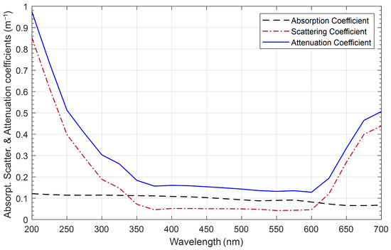
Figure 6.
Attenuation, absorption, and scattering coefficients for pure water as a function of wavelength when [5,6].
5. OCDMA Performance Analysis
The BER evolution is affected by several parameters, such as the proposed receiver sensitivity and limitations, the channel turbulences and transmission parameters, the modulation parameters, multiple-user interference, and the coding parameters. For the proposed MAIC receiver, we can neglect the effect of multiple-user interference in the BER analysis. To evaluate BER, we first must calculate the optical signal-to-noise ratio () which is dependent on the receiver parameters such as the PIN photodetector responsivity , the gain of the used preamplifier at the PIN output , the value of the PIN dark current , the receiver noise figure , the receiver load resistance , and the receiver electrical bandwidth . According to [6], the average can be expressed as
where x is the excess noise factor and equal to 0.5. Consequently, to evaluate the instantaneous (, the irradiance effect must be taken into consideration in our BER analysis. So, the () can be written as follows [12,13,14,15,16]:
In the current published research for underwater communications, the M-DPPM scheme plays a key role in improving the BER performance results compared with the on–off keying (OOK) modulation scheme, frequency shift keying (FSK) modulation scheme, and quadrature amplitude modulation (QAM) schemes and gives approximately the same results as the phase shift keying (PSK) modulation scheme. But due to the complexity of the PSK, we use the DPPM scheme in the proposed system, and the probability of error can be written as follows [5]:
where is the threshold value based on the receiver decision circuit and is the DPPM system multiplicity. Due to the use of Manchester encoding, the proposed MAIC receiver integrator integrates the received signal over half the chip duration .
Then the overall BER performance can be expressed as
where represents the bit error probability when using the HPC. Each HPC sequence is defined by a code length L = and a code weight of 2n, where denotes the ith prime number and n is the number of code words in each sequence. The total number of generated code sequences can be expressed as
where represents the minimum prime number used in the code construction.
The maximum number of active users can be defined by out of , and the remaining number of users were being inactive.
is a random variable that can be expressed as
The number of users active in group #1 can be represented by as a random variable, which can be realized by , and its probability can be expressed as
where and umax = min(N, P1), and umin = max(N+ P1 − K, 1) and the total probability of error according to the HPC can be expressed by the following [36,37,38,39,40,41,42,43,44]:
where and are the number of users causing interference for the desired user in the first and second group, respectively.
6. Results and Discussions
In our simulations, we use the following parameter values, illustrated in Table 5, and use C = 0.03 is the chlorophyll concentration for pure seawater. All results are calculated for line-of-sight case between sender and receiver. The used value of the laser divergence is 0.450 or 7.85 mradian. Also, in our analysis, we set the MAI cancellation depth as equal to 10 dB to assume minimum matching accuracy for the receiver due to the level of optical power received underwater.
Table 5.
The simulation parameters values used.
Figure 7 illustrates the system OSNR versus the optical power received for OOK, 4-DPPM, and 4-DPPM/HPC schemes with Manchester encoding at a 455 nm operating wavelength for a 20 m FSO channel of pure seawater. The results show that for all schemes when the optical power received increases, the OSNR increases, the 4-DPPM/HPC outperforms the other schemes, and the received signal level exceeds the noise at −37.5 dBm optical received power.
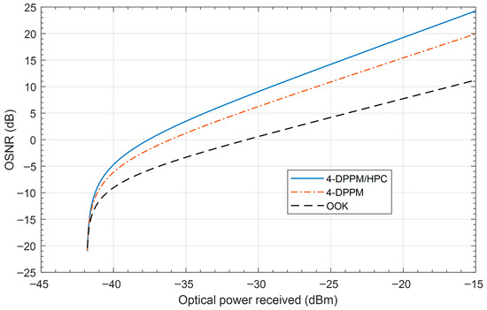
Figure 7.
System OSNR versus the optical power received for different modulation/coding schemes with Manchester encoding at 455 nm, P1 = 5, P2 = 7, C = 0.03, d = 20 m and system multiplicity M = 4.
The OSNR versus the optical received power of the M-DPPM/HPC OCDMA system for different values of system multiplicity M at 455 nm is presented in Figure 8. The results for the 20 m FSO link illustrate that when the system multiplicity increases, the system OSNR increases. When the optical power received reaches −26.5 dBm the OSNR equals 20 dB for the 128-DPPM/HPC scheme compared to 14 dB for the 4-DPPM/HPC scheme; this means the OSNR improves by 6 dB when the system multiplicity increases by a factor of 32.
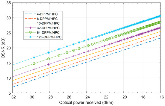
Figure 8.
OSNR versus the optical power received for the M-DPPM/HPC OCDMA system with Manchester encoding for different values of system multiplicity M at 455 nm, P1 = 5, P2 = 7, C = 0.03, d = 20 m.
Figure 9 presents the system OSNR versus the transmission distance for OOK, 4-DPPM, and 4-DPPM/HPC coding schemes with Manchester encoding at 455 nm in pure seawater. The results show that the when the transmission distance increases, the OSNR is decreased for all coding schemes, but the 4-DPPM/HPC scheme is better than the others because the degradation slope is slower than the other schemes’ slopes. At 10 dB system OSNR, the OOK, 4-DPPM, and 4-DPPM/HPC coding schemes achieve 10 m, 26 m, and 68 m underwater FSO link transmission distance, respectively.
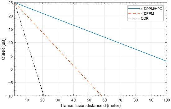
Figure 9.
System OSNR versus the transmission distance for different modulation/coding schemes with Manchester encoding at 455 nm, P1 = 5, P2 = 7, C = 0.03, and system multiplicity M = 4.
The effect of system multiplicity variation on the underwater FSO link transmission distance is illustrated in Figure 10. This figure show that the effect of system multiplicity is clear; when the multiplicity value increases, the link transmission distance increase. For more clarification, at 20 dB system OSNR, the achieved transmission distance is 200 m, 225 m, 255 m, 370 m, 390 m, and 425 m when M equals 16, 32, 64, 128, 256, and 512, respectively. Overall, the results show that when the transmission distance increases, the system OSNR is decreased due to the degradation in the optical power received.
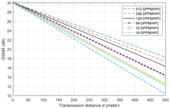
Figure 10.
OSNR versus the transmission distance of the M-DPPM/HPC OCDMA system with Manchester encoding for different values of system multiplicity M at 455 nm, P1 = 5, P2 = 7, C = 0.03.
Figure 11 presents the underwater FSO-CDMA system BER performance versus the transmission distance for different modulation/coding schemes with Manchester encoding at 455 nm, P1 = 5, P2 = 7, C = 0.03, and system multiplicity M = 4. This figure shows that the system BER increases when the link transmission distance increases and the system using the 4-DPPM/HPC coding scheme outperforms the other systems due to the use of HPC increasing the optical power received and enhancing the system OSNR. At 10−9 system BER, the OOK helps the system to communicate over 5 m, the distance increases to 17 m when the 4-DPPM scheme is used, and the hybrid 4-DPPM/HPC coding scheme helps the system to communicate over 42 m under the pure seawater FSO channel. When the system multiplicity increases, the BER decreases, as shown in Figure 12. But at the higher values of system multiplicity, the system BER performance variation decreased compared to the lower multiplicity values. Furthermore, at a BER equal to 10−9, the system that uses 1024 and 512 multiplicities can communicate over 438 m and 430 m, respectively, compared to 250 m and 140 m when the 128 and 32 system multiplicities are used. This is due to the degradation of the system, stopping it from making the true decision at the receiver side.
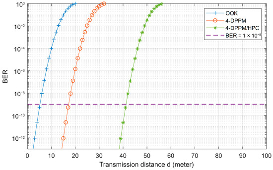
Figure 11.
System BER performance versus the transmission distance for different modulation/coding schemes with Manchester encoding at 455 nm, P1 = 5, P2 = 7, C = 0.03, and system multiplicity M = 4.
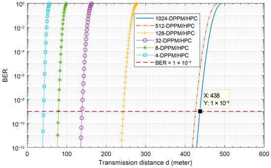
Figure 12.
BER performance versus the transmission distance of the M-DPPM/HPC OCDMA system with Manchester encoding for different values of system multiplicity: M at 455 nm, P1 = 5, P2 = 7, C = 0.03.
Figure 13 investigates the effect of the M-DPPM/HPC scheme on FSO-CDMA system BER performance versus the number of active users over a 438 m underwater channel at 455 nm. The results show that for any value for system multiplicity, when the number of users increases, the BER performance also increases. This is depending on the amount of MAI caused in the multiple-access channel and the amount of interference cancelled by the MAIC receiver. On the other hand, the system of higher multiplicity can accommodate a number of active users higher than the systems of lower multiplicities. Moreover, when BER equals 10−9, the system of 1024 multiplicity can accommodate 156 users simultaneously, which uses 156 sequences out of 160 available sequences. Compared to the system with a multiplicity of 32, the system can accommodate 26 simultaneously.
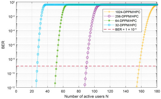
Figure 13.
BER performance as a function of the number of active users of the M-DPPM/HPC OCDMA system with Manchester encoding for various values of system multiplicity: M at 455 nm, with P1 = 5, P2 = 7, C = 0.03.
Despite the use of light-weight code compared to the results of heavy codes in [5,6], the system proposed in this paper has proven that it is possible to obtain large transmission distance in optical wireless communication underwater. Finally, due to the small length of the used code sequence, we were able to obtain a data rate of up to 8.33 Gbps per user, calculated as follows.
The bit rate R_b equals ((1)/(T_b)(Log)_2 (M)), where T_b is the bit time equals the code length multiplied by the chip time duration as T_b = L T_C = 24 × 5 ps = 120 ps, and the bit rate equals 8.33 Gbps for M equals 2 and 75 Gbps for M equals 512.
7. Conclusions
In this paper, we explore and introduce a new hybrid M-ary DPPM/HPC underwater optical wireless CDMA system with an MAIC receiver. This study examines the impact of modulation and coding parameters on the system’s bit error rate (BER) performance, transmission distance, and capacity. We compare the performance of the proposed coding scheme with that of the OOK modulation scheme and the M-ary DPPM scheme. Manchester encoding is applied to all schemes to enhance system power efficiency and BER performance. The principles behind the construction and correlation of the HPC are analyzed, and the underwater wireless optical channel’s power budget, optical signal-to-noise ratio (OSNR), and BER performance are assessed. MATLAB simulations (R2025b) of the proposed system demonstrate that the 1024-DPPM/HPC wireless optical CDMA system, utilizing Manchester encoding and the MAIC receiver, can support 156 users simultaneously over a 438 m transmission distance with a 10–9 BER and a data rate of 8.33 Gbps per user. From the simulation results, we can conclude that the proposed system can practically be used to obtain huge communication coverage underwater. Future work will focus on increasing the number of code words used in the proposed code to enhance code weight and the number of code sequences, and thereby improve BER performance, extend the transmission distance, and accommodate more active users simultaneously.
Author Contributions
Conceptualization, M.A.M. and Y.B.S.; methodology, M.A.M. and M.T.; software, M.A.M.; validation, M.A.M., Y.B.S. and Y.S.A.; formal analysis, M.A.M.; investigation, M.A.M., Y.B.S., Y.S.A. and M.T.; resources, M.A.M.; data curation, M.A.M.; writing—original draft preparation, M.A.M.; writing—review and editing, Morsy A. Morsy and Y.B.S.; visualization, Morsy A. Morsy and Y.S.A.; supervision, Morsy A. Morsy; project administration, Y.B.S.; funding acquisition, Y.B.S. All authors have read and agreed to the published version of the manuscript.
Funding
The authors extend their appreciation to the ongoing research funding programme, (ORF-2025-270), King Saud University, Riyadh, Saudi Arabia.
Institutional Review Board Statement
Not applicable.
Data Availability Statement
The data that support the findings of this study are available from the corresponding author upon reasonable request.
Conflicts of Interest
The authors declare no conflicts of interest.
References
- Álvarez-Roa, C.; Álvarez-Roa, M.; Raddo, T.R.; Jurado-Navas, A.; Castillo-Vázquez, M. Cooperative Terrestrial–Underwater FSO System: Design and Performance Analysis. Photonics 2024, 11, 58. [Google Scholar] [CrossRef]
- Shen, C.; Guo, Y.; Oubei, H.M.; Ng, T.K.; Liu, G.; Park, K.H.; Ho, K.T.; Alouini, M.S.; Ooi, B.S. 20-meter underwater wireless optical communication link with 1.5 Gbps data rate. Opt. Express 2016, 24, 25502–25509. [Google Scholar] [CrossRef]
- Lu, C.; Wang, J.; Li, S.; Xu, Z. 60m/2.5 Gbps underwater optical wireless communication with NRZ-OOK modulation and digital nonlinear equalization. In Proceedings of the 2019 Conference on Lasers and Electro-Optics (CLEO), San Jose, CA, USA, 5–10 May 2019; IEEE: New York, NY, USA; pp. 1–2. [Google Scholar]
- Du, J.; Wang, Y.; Fei, C.; Chen, R.; Zhang, G.; Hong, X.; He, S. Experimental demonstration of 50-m/5-Gbps underwater optical wireless communication with low-complexity chaotic encryption. Opt. Express 2021, 29, 783–796. [Google Scholar] [CrossRef] [PubMed]
- Ismail, M.A.M.; Saleh, K. Performance analysis toward 880 m/4.255 Gbps underwater optical wireless communication CDMA network based on hybrid M-ary differential pulse position modulation and double length modified prime code. Opt. Quantum Electron. 2024, 56, 668. [Google Scholar] [CrossRef]
- Ismail, M.A.M.; Saleh, K. A 930 m/180 Gbps*User Underwater Coherent Optical Code-Division Multiple-Access Network Based on Hybrid 256-Differential Pulse Position Modulation and Weighted Modified Prime Code Sequence. Photonics 2024, 11, 368. [Google Scholar] [CrossRef]
- Hassan, W.H.; Sabril, M.S.; Jasman, F.; Idrus, S.M. Experimental study of light wave propagation for underwater optical wireless communication. J. Commun. 2022, 17, 23–29. [Google Scholar] [CrossRef]
- Baykal, Y.; Ata, Y.; Gökçe, M.C. Underwater turbulence, its effects on optical wireless communication and imaging: A review. Opt. Laser Technol. 2022, 156, 108624. [Google Scholar] [CrossRef]
- Kou, L.; Zhang, J.; Zhang, P.; Yang, Y.; He, F. Composite channel modeling for underwater optical wireless communication and analysis of multiple scattering characteristics. Opt. Express 2023, 31, 11320–11334. [Google Scholar] [CrossRef] [PubMed]
- Liu, X.; Yi, S.; Zhou, X.; Fang, Z.; Qiu, Z.J.; Hu, L.; Cong, C.; Zheng, L.; Liu, R.; Tian, P. 34.5 m underwater optical wireless communication with 2.70 Gbps data rate based on a green laser diode with NRZ-OOK modulation. Opt. Express 2017, 25, 27937–27947. [Google Scholar] [CrossRef]
- Liu, W.; Zhang, L.; Huang, N.; Xu, Z. Wide dynamic range signal detection for underwater optical wireless communication using a PMT detector. Opt. Express 2023, 31, 25267–25279. [Google Scholar] [CrossRef]
- Wang, J.; Lu, C.; Li, S.; Xu, Z. 100 m/500 Mbps underwater optical wireless communication using an NRZ-OOK modulated 520 nm laser diode. Opt. Express 2019, 27, 12171–12181. [Google Scholar] [CrossRef] [PubMed]
- Mohammed, S.; Nameer, O.; Salah, A.A.; Hussein, M.A. Underwater optical wireless communication system performance improvement using convolutional neural networks. AIP Adv. 2023, 13, 045302. [Google Scholar] [CrossRef]
- Zhang, W.; Wang, L.; Wu, X.; Fei, L.; Peng, H.; Wen, K.; Zhao, Y. Performance Evaluation of Maximum Ratio Combining Diversity Technology and Traditional System Based on Comprehensive Noise Analysis in Underwater Wireless Optical Communication. Photonics 2023, 10, 1388. [Google Scholar] [CrossRef]
- Hu, S.; Mi, L.; Zhou, T.; Chen, W. 35.88 attenuation lengths and 3.32 bits/photon underwater optical wireless communication based on photon-counting receiver with 256-PPM. Opt. Express 2018, 26, 21685–21699. [Google Scholar] [CrossRef]
- Shen, T.; Guo, J.; Liang, H.; Li, Y.; Li, K.; Dai, Y.; Ai, Y. Research on a Blue–Green LED Communication System Based on an Underwater Mobile Robot. Photonics 2023, 10, 1238. [Google Scholar] [CrossRef]
- Chen, Y.; Kong, M.; Ali, T.; Wang, J.; Sarwar, R.; Han, J.; Guo, C.; Sun, B.; Deng, N.; Xu, J. 26 m/5.5 Gbps air-water optical wireless communication based on an OFDM-modulated 520-nm laser diode. Opt. Express 2017, 25, 14760–14765. [Google Scholar] [CrossRef]
- Chen, D.; Wang, J.; Li, S.; Xu, Z. Effects of air bubbles on underwater optical wireless communication. Chin. Opt. Lett. 2019, 17, 100008. [Google Scholar] [CrossRef]
- Rong, Y.; Nordholm, S.; Duncan, A. On the capacity of underwater optical wireless communication systems. In Proceedings of the 2021 Fifth Underwater Communications and Networking Conference (UComms), Lerici, Italy, 31 August–2 September 2021; IEEE: New York, NY, USA; pp. 1–4. [Google Scholar]
- Geldard, C.T.; Guler, E.; Hamilton, A.; Popoola, W.O. An empirical comparison of modulation schemes in turbulent underwater optical wireless communications. J. Lightw. Technol. 2022, 40, 2000–2007. [Google Scholar] [CrossRef]
- Huang, X.; Yang, F.; Song, J. Hybrid LD and LED-based underwater optical communication: State-of-the-art, opportunities, challenges, and trends. Chin. Opt. Lett. 2019, 17, 100002. [Google Scholar] [CrossRef]
- Gabriel, C.; Khalighi, M.A.; Bourennane, S.; Léon, P.; Rigaud, V. Monte-Carlo-based channel characterization for underwater optical communication systems. J. Opt. Commun. Netw. 2013, 5, 1–12. [Google Scholar] [CrossRef]
- Saeed, N.; Celik, A.; Al-Naffouri, T.Y.; Alouini, M.S. Underwater optical wireless communications, networking, and localization: A survey. Ad Hoc Netw. 2019, 94, 101935. [Google Scholar] [CrossRef]
- Han, S.; Noh, Y.; Liang, R.; Chen, R.; Cheng, Y.J.; Gerla, M. Evaluation of underwater optical-acoustic hybrid network. China Commun. 2014, 11, 49–59. [Google Scholar] [CrossRef]
- Kaushal, H.; Kaddoum, G. Underwater optical wireless communication. IEEE Access 2016, 4, 1518–1547. [Google Scholar] [CrossRef]
- Farr, N.; Bowen, A.; Ware, J.; Pontbriand, C.; Tivey, M. An integrated, underwater optical/acoustic communications system. In Proceedings of the OCEANS’10 IEEE SYDNEY, Sydney, NSW, Australia, 24–27 May 2010; IEEE: New York, NY, USA; pp. 1–6. [Google Scholar]
- Willner, A.E.; Zhao, Z.; Ren, Y.; Li, L.; Xie, G.; Song, H.; Liu, C.; Zhang, R.; Bao, C.; Pang, K. Underwater optical communications using orbital angular momentum-based spatial division multiplexing. Opt. Commun. 2018, 408, 21–25. [Google Scholar] [CrossRef]
- Al-Zhrani, S.; Bedaiwi, N.M.; El-Ramli, I.F.; Barasheed, A.Z.; Abduldaiem, A.; Al-Hadeethi, Y.; Umar, A. Underwater optical communications: A brief overview and recent developments. Eng. Sci. 2021, 16, 146–186. [Google Scholar] [CrossRef]
- Lu, H.; Jiang, M.; Cheng, J. Deep learning aided robust joint channel classification, channel estimation, and signal detection for underwater optical communication. IEEE Trans. Commun. 2020, 69, 2290–2303. [Google Scholar] [CrossRef]
- Zhu, S.; Chen, X.; Liu, X.; Zhang, G.; Tian, P. Recent progress in and perspectives of underwater wireless optical communication. Prog. Quantum Electron. 2020, 73, 100274. [Google Scholar] [CrossRef]
- Zhao, Y.; Wang, A.; Zhu, L.; Lv, W.; Xu, J.; Li, S.; Wang, J. Performance evaluation of underwater optical communications using spatial modes subjected to bubbles and obstructions. Opt. Lett. 2017, 42, 4699–4702. [Google Scholar] [CrossRef]
- Zhou, H.; Zhang, M.; Wang, X.; Ren, X. Design and implementation of more than 50m real-time underwater wireless optical communication system. J. Lightw. Technol. 2022, 40, 3654–3668. [Google Scholar] [CrossRef]
- Nguyen, C.T.; Nguyen, M.T.; Mai, V.V. Underwater optical wireless communication-based IoUT networks: MAC performance analysis and improvement. Opt. Switch. Netw. 2020, 37, 100570. [Google Scholar] [CrossRef]
- Xu, J. Underwater wireless optical communication: Why, what, and how? Chin. Opt. Lett. 2019, 17, 100007. [Google Scholar] [CrossRef]
- Spagnolo, G.S.; Cozzella, L.; Leccese, F. Underwater optical wireless communications: Overview. Sensors 2020, 20, 2261. [Google Scholar] [CrossRef]
- Morsy, M.A.; Aly, M.H. A new hybrid prime code for OCDMA network multimedia applications. Electronics 2021, 10, 2705. [Google Scholar] [CrossRef]
- Ismail, M.A.M.; Alsayyari, A.; Galal, O.H. Performance analysis of optical code division multiple access networks for multimedia applications using multilength weighted modified prime codes. Opt. Eng. 2019, 58, 035101. [Google Scholar] [CrossRef]
- Morsy, M.A. Coherent OCDMA network based on a new BER performance equalization technique for multimedia applications. Opt. Quantum Electron. 2023, 55, 167. [Google Scholar] [CrossRef]
- Rahmani, M.; Cherifi, A.; Sabri, G.N.; Al-Rayif, M.I.; Dayoub, I.; Bouazza, B.S. A novel 260 Gb/s 2D-OCDMA-FSO multiplexing system’s performance evaluation for upcoming generations of high-speed wireless optical networks. Opt. Quantum Electron. 2024, 56, 449. [Google Scholar] [CrossRef]
- Morsy, M.A.; Alsayyari, A.S. Performance analysis of coherent BPSK-OCDMA wireless communication system. Wirel. Netw. 2020, 26, 4491–4505. [Google Scholar] [CrossRef]
- Ismail, M.M.; Alsayyari, A. Performance Analysis of Optical CDMA Wireless Communication System Based on Double Length Modified Prime Code for Security Improvement. IET Commun. 2020, 14, 1139–1146. [Google Scholar]
- Rahmani, M.; Sabri, G.N.; Cherifi, A.; Karar, A.S.; Mrabet, H. Massive capacity of novel three-dimensional OCDMA-FSO system for next generation of high-data wireless networks. Trans Emerg. Tel. Technol. 2024, 35, e4871. [Google Scholar] [CrossRef]
- Rahmani, M.; Cherifi, A.; Sabri, G.N.; Al-Rayif, M.I.; Dayoub, I.; Bouazza, B.S. Performance investigation of 1.5 Tb/s optical hybrid 2D-OCDMA/OFDM system using direct spectral detection based on successive weight encoding algorithm. Opt. Laser Technol. 2024, 174, 110666. [Google Scholar] [CrossRef]
- Morsy, M.A.; Alsayyari, A.S. Multi-rate OCDMA system BER performance evaluations for different ML-code sequences. Opt. Quantum Electron. 2019, 51, 198. [Google Scholar] [CrossRef]
- Morsy, M.A. Analysis and design of weighted MPC in incoherent synchronous OCDMA network. Opt. Quantum Electron. 2018, 50, 387. [Google Scholar] [CrossRef]
- Morsy, M.A.; Rajab, H.S.A.; Al-Obaidan, H.M. Performance of passive OCDMA networks for different encoder/decoder delay lines. Int. J. Opt. Appl. 2013, 3, 19–26. [Google Scholar]
- Alsayyari, A. FSO-CDMA system performance enhancement based on new hybrid code and M-ary digital pulse position modulation technique. Opt. Quantum Electron. 2023, 55, 669. [Google Scholar] [CrossRef]


Disclaimer/Publisher’s Note: The statements, opinions and data contained in all publications are solely those of the individual author(s) and contributor(s) and not of MDPI and/or the editor(s). MDPI and/or the editor(s) disclaim responsibility for any injury to people or property resulting from any ideas, methods, instructions or products referred to in the content. |
© 2025 by the authors. Licensee MDPI, Basel, Switzerland. This article is an open access article distributed under the terms and conditions of the Creative Commons Attribution (CC BY) license.