Abstract
This paper presents a high-efficiency wireless power transfer (WPT) architecture employing a resonant inductive coupling to power smart sensor nodes in remote or sealed environments, where conventional power delivery is unfeasible. The system integrates a photovoltaic (PV) energy source with a step-down DC-DC converter based on the LM2596 buck regulator to adjust the voltage from the PV. The proposed conditioned power system supplies the entire electronic circuit consisting of a PWM modulator based on an NE555, which drives an IR2110 gate driver connected to a Class D power amplifier. The amplifier excites a pair of high-Q resonant coils designed for mid-range inductive coupling. On the receiver side, the inductively coupled AC signal is rectified and regulated through an AC-DC conversion stage to charge a secondary energy storage unit. The design eliminates the need for physical electrical connections, ensuring efficient, contactless energy transfer. The proposed system operates at a resonant frequency of 24.46 kHz and achieves up to 80% transmission efficiency at a distance of 113 mm. The receiver provides a regulated DC output between 4.80 V and 4.97 V, sufficient to power low-consumption smart sensors.
1. Introduction
Typically, conductive materials, characterized by free electrons loosely bonded to their atomic nuclei, are employed to transmit electrical energy, whose structure facilitates the flow of electric current. To maintain an electrical connection between a power source and a receiver, conductive wires are insulated to ensure safety and efficiency [1,2]. However, the reliance on conductive wires can be costly, with billions of dollars spent annually on electrical transmission infrastructure [2]. Additionally, there are numerous locations where accessing electricity poses significant challenges. To address these issues, this work aims to contribute to the concept of transferring electrical power from source to load without the use of conductive wires, utilizing resonant inductive coupling technology while avoiding ionization of the surrounding area [3,4].
The notion of transmitting electrical energy without conductive links was initially proposed by pioneers such as Hertz and Marconi. Utilizing Maxwell’s theory from 1862, these researchers demonstrated that electrical energy could indeed be conveyed from one point to another without any conductive medium. In the early 20th century, Nikola Tesla explored the transmission of 300 kW of power without physical connections, employing radio waves in his experiments, as shown in Figure 1 [5]. Building upon these foundational ideas, significant advancements in technology and science have led to extensive research in wireless energy transmission.
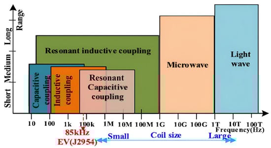
Figure 1.
Classification of Wireless Power Transfer (WPT) techniques by operating frequency.
Supplying electrical energy, either in direct current (DC) or alternating current (AC), to a high-frequency generator, which feeds into the transmitting structure; emitting electromagnetic waves from the transmitting structure that propagate toward the receiving structure; and capturing the radiated energy with the receiving structure, converting it into alternating voltage. The various methods for transmitting energy without the use of conductive wires are outlined in the structure depicted in Figure 1.
In this work, we propose a complete wireless power transfer system that is fully powered by a photovoltaic source and experimentally validated, which is rarely addressed in existing studies.
Another original aspect of our implementation is the use of low-frequency resonant coupling around 24 kHz, which still achieves efficiencies close to 80%, in contrast to many high-frequency WPT systems reported in the literature.
This paper also presents a full end-to-end realization of the WPT chain, including PV conditioning, NE555-based excitation, IR2110 driving (by international rectifier, El Segundo, CA, USA), Class-D amplification, resonant inductive coupling, AC–DC conversion, and battery charging for autonomous sensors.
The main contributions of this paper can be summarized as follows:
- The implementation and experimental validation of a wireless power transfer (WPT) system based on resonant inductive coupling;
- The design and realization of a class D amplifier and AC/DC converter to efficiently drive the transmitting coil;
- The demonstration of magnetic induction phenomena and their role in near-field power transfer;
- The analysis of measured waveforms and coupling efficiency to assess system performance.
This study adopts an experimental approach to demonstrate the phenomena associated with magnetic induction and the transfer of electrical energy in the near field without wires [5,6,7]. In Section 2, the fundamental principles of wireless energy transmission are introduced. Section 3 showcases the experimentation, where the resonant inductive coupling is explored facilitated by an AC/DC converter. Section 4 presents the experimental validation, while Section 5 introduces the application and Section 6 presents the conclusions.
2. Fundamentals Principles of Wireless Power Transfer
2.1. Overview of Electrical Power Transmission Through Magnetic Coupling
The transportation of electrical power through magnetic coupling in the near field, utilizing inductive coupling is an established method. The process involves several key steps: (1) A high-frequency generator supplies electricity to a transmitter coil, which generates a magnetic field [8,9]; (2) This magnetic energy is then captured by a receiving coil that detects the electromagnetic waves. In this scenario, various power aspects are considered: the source power, transmitted power, received power, and the power consumed by the load, as described in Figure 2. WPT via magnetic induction is a well-recognized technique that has been effectively utilized in transformers for many years. A magnetic core facilitates the inductive coupling between primary and secondary coils [10,11,12]. Moreover, the ability to transmit energy through induction in air, where the primary and secondary coils are physically distanced, has been known for over a century [13,14]. This method is often referred to as tight coupling and is characterized by a decrease in energy transmission efficiency when the distance between coils exceeds their diameter or when they are misaligned. The effectiveness of this power transfer is influenced by the coupling factor (k) between the inductors as well as their quality factor (Q). Nevertheless, advancements in this technique have enhanced its performance, making it suitable for applications like smartphone charging [15]. By employing an array of coils, this approach provides considerable flexibility in positioning the receiver coil relative to the transmitter. Figure 3 illustrates the used principle.
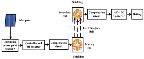
Figure 2.
Block diagram of the solar-powered electromagnetic WPT system using resonant inductive coupling.
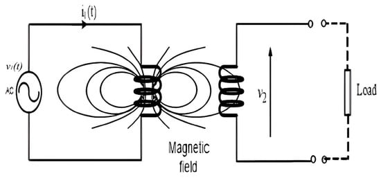
Figure 3.
Schematic representation of WPT.
2.2. Mathematical Framework
According to Faraday’s law, a changing magnetic flux through a loop-shaped conductor induces an electromotive force, expressed as:
where is the field generated by the changes in magnetic flux (ΦB). According to this principle, when two coils are positioned near one another, the current (i) flowing through the first coil (L1) produces a magnetic flux () that is transferred to the second inductive coil (L2). This interaction induces a voltage (electromotive force or e.m.f.) in L2, as described by Faraday’s law.
Furthermore, based on Neumann’s formula, it is possible to express the relationship mathematically, based on:
where M21 represents the mutual inductance, defined as the measure of the magnetic coupling between the coils. This mutual inductance captures the flow generated by the primary current.
When the secondary circuit is completed, as illustrated in Figure 3, a current will circulate in the secondary coil. This current, in turn, generates its own magnetic field, which opposes the change in flux (Φ21) according to Lenz’s law. Consequently, we observe that both induction and self-induction phenomena occur simultaneously.
Thus, for the two coils, we can formulate relationships accordingly. Experimental evidence indicates that the coefficients of mutual induction are equivalent, and their maximum value aligns with that of an inductance, measured in Henrys. Therefore, we can conclude that mutual inductance (M) serves as the key parameter characterizing the interaction between two coils.
and
3. Implementation of Resonant Inductive Coupling
To enhance the effectiveness of the experiment discussed in [16], it was implemented a resonant inductive coupling. Magnetic Resonance WPT (MRWPT), often referred to as weakly coupled WPT, is an innovative technique that leverages electromagnetic resonance for energy transmission [17,18]. The foundational concepts of this method were pioneered by the Massachusetts Institute of Technology in 2005, with experimental validation following in 2007 [2,3]. This approach employs a combination of a coil and a capacitor to function as a resonator, enabling the transfer of electrical energy through electromagnetic resonance between the transmitting and receiving coils. With resonant inductive coupling, WPT can facilitate the transmission of electrical energy across distances of several meters, provided that the primary source possesses adequate power [19,20,21].
3.1. Resonance Principle of an LC Circuit
In this section, a voltage is applied to the circuit depicted in Figure 4.
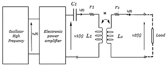
Figure 4.
Resonant circuit.
Equating the circuit in Figure 4 allows us to write:
And,
It is obtained: and .
At resonance it is obtained: and reduces to: .
Using Equations (8) and (9), we have:
and
The impedance seen from the primary is:
The second term of Equation (12) represents the impedance of the secondary referred to the primary, which ensures the inductive coupling between two coils.
The energy stored in the inductance being: and that in the capacitance is: .
Furthermore, the power delivered to the first coil is calculated as follows:
and, the power transmitted to the load is:
All calculations result in:
The efficiency of near-field inductive coupling is:
By exploiting Equations (13)–(15), we can determine the energy efficiency of the resonant inductively coupled circuit.
3.2. System Architecture
This section describes the design and functional components of the proposed WPT system based on resonant inductive coupling, intended to power smart sensor nodes in remote or sealed environments. The system is composed of several key subsystems: energy harvesting, signal generation and amplification, wireless energy transmission, and energy reception and storage. A block diagram illustrating the overall architecture is shown in Figure 5.
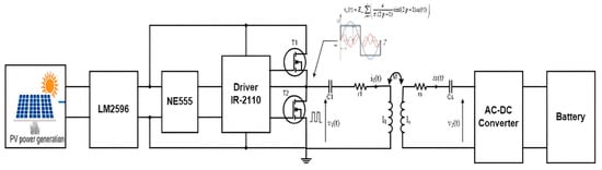
Figure 5.
Proposed system block diagram for resonant inductive coupling powered by a class D amplifier.
3.2.1. Energy Harvesting and Power Conditioning
The system begins with a photovoltaic (PV) panel that captures ambient solar energy and converts it into a variable DC voltage. Due to fluctuations in solar irradiance, the output voltage is unstable and requires regulation. A buck-type DC-DC converter based on the LM2596 switching regulator is employed to step down and stabilize the voltage to a level suitable for the downstream circuitry. The LM2596 was selected for its high efficiency, integrated control circuitry, and compatibility with low-power embedded systems [22].
3.2.2. PWM Signal Generation and Gate Driving
The regulated voltage powers a pulse-width modulation (PWM) signal generator built using the NE555 timer IC (Texas instrumentations, Dallas, TX, USA), configured in a stable mode. The frequency of the PWM signal is tuned to match the resonant frequency of the coupled coils (typically in the range of 100 kHz to 500 kHz), ensuring efficient energy transfer. The PWM output is insufficient to directly drive power MOSFETs, thus an IR2110 gate driver is used to interface between the NE555 and the Class D amplifier stage. The IR2110 can drive both high-side and low-side MOSFETs in a half-bridge configuration, offering robust isolation and fast switching performance [23].
3.2.3. Class D Amplifier and Resonant Transmission
The PWM signal, boosted by the gate driver, controls a full-bridge Class D amplifier composed of low-RDS(on) MOSFETs. This stage converts the DC input into a high-frequency AC signal, which is applied to a resonant transmitting coil (L1) in series with a tuning capacitor (C1). The coil is designed to resonate at the frequency of the amplifier’s output, maximizing the efficiency of magnetic field generation. The use of Class D amplification ensures minimal conduction and switching losses, making it well-suited for low-power wireless systems [24].
3.2.4. Inductive Coupling and Energy Reception
The generated magnetic field is captured by a spatially aligned receiver coil (L2), tuned with a parallel capacitor (C2) to form a resonant tank circuit. This coil picks up the transmitted energy through magnetic resonance, even over moderate distances or through non-metallic barriers. The received AC signal is then passed through a full-wave rectifier and low-pass filter to obtain a regulated DC voltage.
The chosen resonant frequency of 24.46 kHz is determined by the coil inductance (approximately 479 µH) and the capacitor values needed to achieve resonance. Operating at this lower frequency reduces switching losses in the Class-D amplifier, minimizes skin effect, and ensures stable operation in environments where high-frequency systems may suffer higher attenuation.
3.2.5. Energy Storage and Sensor Powering
The rectified DC output is used to charge a rechargeable battery (e.g., Li-ion or LiPo), which serves as the energy buffer for the smart sensor node. This storage solution enables continuous and autonomous operation of the sensor, even during periods of insufficient solar input or transmission interruptions. The sensor node may consist of environmental monitoring modules, microcontrollers, and low-power wireless transceivers, depending on the target application. By supplying a series LC circuit with a square voltage, then the following resonance is obtained:
The coupling is resonant for the two coils of the circuit shown in Figure 5, and the following is obtained:
The efficiency of the inductive coupling between the two coils is:
4. Experimental Validation
To demonstrate the process of transmitting electrical energy through resonant inductive coupling, two coils were constructed, each measuring 105 mm in diameter and comprising 50 turns. These coils were fashioned using enameled winding wire with a thickness of 0.85 mm. Using the provided data Table 1, The WPT system demonstrates good overall efficiency, with values approaching 80% in optimal conditions. The variation with distance highlights the importance of precise coil design and alignment. For practical deployment, the system should be tuned to operate around the coupling distance that yields maximum efficiency (around 113–120 mm in this case) or includes adaptive tuning mechanisms to maintain resonance under variable conditions.

Table 1.
Data measurement.
The distance between the coils was adjusted using a mechanical ruler with ±1 mm accuracy, and both coils were kept coaxially aligned using a fixed wooden support to minimize lateral displacement. All measurements were performed indoors at approximately 22 °C under stable environmental conditions and without nearby metallic objects to avoid unintended coupling.
The measured inductance, parasitic resistance, and coil spacing values were used directly in the mutual inductance, equivalent impedance, and efficiency formulas presented in Section 2, ensuring consistency between the theoretical model and the experimental setup.
In this experiment aimed at determining efficiency, illustrated in Figure 6, we loaded the resonant circuit with a 5 W, 12 V tungsten lamp with a resistance value of 28.7 Ω, while maintaining resonance conditions for both coils. and .
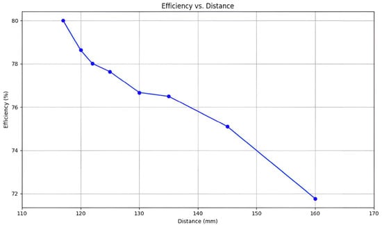
Figure 6.
Variation in power transmission efficiency with distance (d) between coils.
4.1. Inductance and Q-Factor Measurements
The coil inductances (L1, L2) were measured using a precision LCR meter (PM6303 Philips, Amsterdam, The Netherlands) at 1 kHz and confirmed near the resonant frequency using an impedance analyzer (Table 2). Parasitic (series) resistance was measured by the same LCR meter at the operating frequency. The unloaded quality factor was computed from the frequency-domain definition.
Table 2.
Component values.
4.2. Discussion
The calculated efficiencies range from approximately 71.8% to 80%, depending on the distance between transmitting and receiving coils (Figure 6). As expected, efficiency increases as the distance decreases—due to stronger magnetic coupling between the coils, leading to better energy transfer. The peak efficiency (80%) occurs at 113 mm, indicating optimal alignment and coupling at this range. Below 117 mm, efficiency begins to slightly drop again, possibly due to:
- Overcoupling or detuning between the coils.
- Increased eddy current losses or parasitic effects at close proximity.
- Impedance mismatch in the rectification or loading stage.
This trend confirms the presence of a critical coupling distance beyond which the system becomes less efficient—a common phenomenon in resonant inductive systems illustrated in Figure 7.
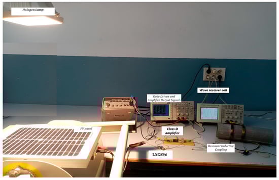
Figure 7.
Experimental tests of resonant inductive coupling using a DC-AC converter.
Figure 8 shows the signals from a wireless power transfer system. The signals are as follows:
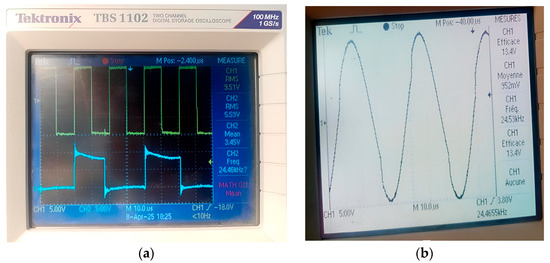
Figure 8.
(a) Oscilloscope capture of gate-driven and amplifier output signals. (b) Sinusoidal voltage at receiver coil output.
Channel 1 (CH1—yellow): square waveform representing the gate signal generated by the NE555 timer and fed into the IR2110 MOSFET driver. The waveform has a peak-to-peak voltage corresponding to an RMS value of 9.51 V. The periodic square pulses indicate proper switching at a stable frequency.
Channel 2 (CH2—blue): output signal from the Class D amplifier connected to the resonant coil. The waveform appears slightly distorted due to resonance and load effects, with an RMS value of 5.59 V and an average (mean) of 3.45 V. The signal frequency is approximately 24.46 kHz, which is consistent with the designed resonant frequency of the inductive link.
This observation confirms that the system is switching efficiently and delivering high-frequency AC power to the resonant circuit for wireless transmission.
In contrast to many existing WPT designs that operate in the hundreds of kilohertz or MHz ranges and use external power supplies, the proposed system operates at a lower resonant frequency and is fully powered by a PV source. This difference in architecture and operating conditions makes direct numerical comparison difficult, but the qualitative distinctions highlight the originality of our contribution.
5. Applications
Resonant inductive coupling using a sinusoidal source and a linear amplifier can be exploited to power intelligent sensors placed in difficult-to-access locations such as force sensors in reinforced concrete, the meteorological field, etc. Indeed, intelligent sensors with a micro-electronic or nano-electronic structure need low energy to charge their battery, ensuring autonomy of operation. It remains, of course, to model, simulate, and design flat coils in order to ensure optimal energy efficiency while minimizing the size of the coils. The goal is to develop more compact and high-performance solutions, while offering an improved esthetic compared to traditional circular coils. This approach would not only reduce the space required for installation but also meet growing demands in terms of design, integration, and performance, all while optimizing thermal dissipation and minimizing energy losses.
6. Conclusions
In this paper, we have presented the measurement techniques employed for energy transfer via resonant inductive coupling within the medium frequency range. Experimental results indicate that resonant coupling at close distances significantly enhances energy efficiency when compared to non-resonant coupling. This improvement facilitates a greater separation between the primary and secondary coils, enabling the transmission of higher power levels. The data gathered from our experiments clearly illustrates the substantial boost in energy efficiency that this method provides.
Furthermore, the excitation frequency used in resonant coupling is considerably lower than that of non-resonant coupling, which allows for greater flexibility in positioning the receiver coil in relation to the transmitter coil. It can be inferred that the power delivered through resonant inductive coupling is influenced by the power source, the excitation frequency, and the dimensions of both the transmitter and receiver coils.
This wireless power transfer technique is particularly suited for powering advanced sensors located in difficult environments. Initially, we conducted a theoretical analysis to demonstrate the inductive coupling between two coils (the transmitter and receiver), showing the potential for wirelessly transmitting electrical power across various environments through a variable magnetic field generated by a high-frequency device. One of the most notable experiments involved a Class D amplifier, which successfully powered a 5 W, 12 V lamp at distances of up to 120 mm between the two coils. Experimental results show that the resonant link reaches a maximum efficiency of 80% at 113 mm separation, with a stable DC output of around 5 V for sensor powering. The overall system demonstrates reliable end-to-end operation, with the PV-powered Class-D stage delivering approximately 4.5 W of usable power.
This advancement holds great potential for remotely powering low-energy electronic devices such as smartphones, guitars, and more. Resonance increases the voltage across the primary coil, which in turn raises the secondary voltage, a principle also observed in electronic ignition systems. The voltages across the coil and capacitor balance each other, resulting in minimal primary impedance and maximum current flow, thereby ensuring efficient power transfer from the primary to the secondary coil.
Looking ahead, our efforts will concentrate on modeling, simulating, and designing planar coils that optimize energy efficiency while maintaining a compact design and improving esthetics compared to traditional circular coils.
Several studies have also explored wireless power transfer for devices located in remote, sealed, or harsh environments, including underground sensors, biomedical implants, and structures with limited accessibility. These works highlight the relevance of resonant inductive links when wired power delivery is impractical. This context supports the motivation of the present system, which targets autonomous sensing in inaccessible environments.
Author Contributions
Conceptualization, A.C. and A.H.; methodology, A.H. and H.M.; software and validation A.C., A.H. and V.M.; format analysis and investigation, V.M., A.H. and J.L.A.; resources H.M.; data curation A.C., writing original draft preparation A.C., A.H. and H.M.; writing—review and editing V.M. and A.H.; visualization and supervision H.M. and J.L.A. All authors have read and agreed to the published version of the manuscript.
Funding
This research received no external funding.
Data Availability Statement
Data is contained within the article.
Acknowledgments
The work was performed in the instrumentation laboratory of ENSIT, University of Tunis, Tunisia. So the datasets concerning the paper can be accessed with a help of authors.
Conflicts of Interest
The authors declare no conflicts of interest.
References
- Pahlavan, S.; Shooshtari, M.; Jafarabadi Ashtiani, S. Star-Shaped Coils in the Transmitter Array for Receiver Rotation Tolerance in Free-Moving Wireless Power Transfer Applications. Energies 2022, 15, 8643. [Google Scholar] [CrossRef]
- Pahlavan, S.; Jafarabadi-Ashtiani, S.; Mirbozorgi, S.A. Maze-Based Scalable Wireless Power Transmission Experimental Arena for Freely Moving Small Animals Applications. IEEE Trans. Biomed. Circuits Syst. 2025, 19, 120–129. [Google Scholar] [CrossRef] [PubMed]
- Li, X.; Zhang, Y.; Chen, S.; Zhang, X.; Tang, Y. Small-Signal Models of Resonant Converter with Consideration of Different Duty-Cycle Control Schemes. IEEE Trans. Power Electron. 2021, 36, 13234–13247. [Google Scholar] [CrossRef]
- Kouhalvandi, L.; Ozoguz, S.; Koohestani, M. A Literature Survey with the Focus on Magnetically Coupled Wireless Power Transfer Systems Developed for Engineering and Biomedical Applications. Micromachines 2023, 14, 786. [Google Scholar] [CrossRef] [PubMed] [PubMed Central]
- Fanton, J.-P. Wireless Power Transmission: State of the Art and Perspectives. Int. Rev. Electr. Eng. (IREE) 2019, 14, 205. [Google Scholar] [CrossRef]
- Trigui, A.; Ali, M.; Hached, S.; David, J.-P.; Ammari, A.C.; Savaria, Y.; Sawan, M. Generic Wireless Power Transfer and Data Communication System Based on a Novel Modulation Technique. IEEE Trans. Circuits Syst. I Regul. Pap. 2020, 67, 3978–3990. [Google Scholar] [CrossRef]
- Wei, X.; Wang, Z.; Dai, H. A Critical Review of Wireless Power Transfer via Strongly Coupled Magnetic Resonances. Energies 2014, 7, 4316–4341. [Google Scholar] [CrossRef]
- Kim, Y.; Ling, H. investigation of coupled mode behavior of electrically small meander antennas. Electron. Lett. 2007, 43, 1250–1252. [Google Scholar] [CrossRef]
- Li, Y.; Zhang, L.; Zhao, T.; Zou, L. The electromagnetic compatibility analysis of experimental apparatus based on wireless power transmission. In Proceedings of the 2016 IEEE 11th Conference on Industrial Electronics and Applications (ICIEA), Hefei, China, 5–7 June 2016; pp. 2334–2338. [Google Scholar] [CrossRef]
- Detka, K.; Górecki, K. Wireless Power Transfer—A Review. Energies 2022, 15, 7236. [Google Scholar] [CrossRef]
- Bito, J.; Bahr, R.; Hester, J.G.; Nauroze, S.A.; Georgiadis, A.; Tentzeris, M.M. A Novel Solar and Electromagnetic Energy Harvesting System With a 3-D Printed Package for Energy Efficient Internet-of-Things Wireless Sensors. IEEE Trans. Microw. Theory Tech. 2017, 65, 1831–1842. [Google Scholar] [CrossRef]
- Kimionis, J.; Su, W.; Hester, J.; Bito, J.; He, X.; Lin, T.H.; Tentzeris, M.M. Zero-Power Sensors for Smart Objects: Novel Zero-Power Additively Manufactured Wireless Sensor Modules for IoT Applications. IEEE Microw. Mag. 2018, 19, 32–47. [Google Scholar] [CrossRef]
- Fay, P.; Jena, D.; Maki, P. High-Frequency GaN Electronic Devices; Springer: Cham, Switzerland, 2019. [Google Scholar]
- Jiang, L.; Costinett, D. A high-efficiency GaN-based single-stage6.78 MHz transmitter for wireless power transfer applications. IEEE Trans. Power Electron. 2019, 34, 7677–7692. [Google Scholar] [CrossRef]
- Hassan, A.; Ali, M.; Trigui, A.; Savaria, Y.; Sawan, M. A GaN-BasedWireless Monitoring System for High-TemperatureApplications. Sensors 2019, 19, 1785. [Google Scholar] [CrossRef] [PubMed]
- Cardoso, L.A.L.; Martinez, M.C.; Melendez, A.A.N.; Afonso, J.L. Dynamic inductive power transfer lane design for e-bikes. In Proceedings of the IEEE 19th International Conference on Intelligent Transportation Systems (ITSC), Rio de Janeiro, Brazil, 1–4 November 2016; pp. 2307–2312. [Google Scholar] [CrossRef]
- Haddouk, A.; Mechergui, H. Wireless energy transfer for powering smart sensors. In Proceedings of the 2024 10th International Conference on Control, Decision and Information Technologies (CoDIT), Vallette, Malta, 1–4 July 2024; pp. 3051–3056. [Google Scholar] [CrossRef]
- Molefi, M.; Markus, E.D.; Abu-Mahfouz, A. Wireless Power Transfer for IoT Devices—A Review. In Proceedings of the 2019 International Multidisciplinary Information Technology and Engineering Conference (IMITEC), Vanderbijlpark, South Africa, 21–22 November 2019; pp. 1–8. [Google Scholar] [CrossRef]
- Lee, J.S.; Kwon, H.K.; Song, B.S. Development of a Wireless Power Transfer System for Electric Vehicles. In Proceedings of the IEEE Energy Conversion Congress and Exposition, Cincinnati, OH, USA, 1–5 October 2017. [Google Scholar]
- Jiang, Y.; Wang, Y.; Dong, X. A parametric design method for achieving constant voltage and ZVS under variable frequency phase-shift control for SS resonant wireless energy transmission systems. J. Power Supply 2019, 17, 153–161. [Google Scholar]
- Sun, K.; Niu, W. SPWM inverter control for wireless constant current and voltage charging. World Electr. Veh. J. 2023, 14, 111. [Google Scholar] [CrossRef]
- Esram, T.; Chapman, P.L. Comparison of photovoltaic array maximum power point tracking techniques. IEEE Trans. Energy Convers. 2007, 22, 439–449. [Google Scholar] [CrossRef]
- International Rectifier. IR2110 High- and Low-Side Driver Datasheet; Infineon Technologies: Neubiberg, Germany, 2013. [Google Scholar]
- Kim, J.; Kim, D.; Seo, C. Design of Class-D Power Amplifier for Wireless Power Transfer Systems. IEEE Trans. Power Electron. 2018, 33, 4140–4148. [Google Scholar]
Disclaimer/Publisher’s Note: The statements, opinions and data contained in all publications are solely those of the individual author(s) and contributor(s) and not of MDPI and/or the editor(s). MDPI and/or the editor(s) disclaim responsibility for any injury to people or property resulting from any ideas, methods, instructions or products referred to in the content. |
© 2025 by the authors. Licensee MDPI, Basel, Switzerland. This article is an open access article distributed under the terms and conditions of the Creative Commons Attribution (CC BY) license.